

Lutron Electronics QSGRK-6D, QSGR-8D, QSGR-16D, QSGRK-8D, QSGRM-6D Quick Installation And Operation Manual
...
LUTRON
with DALI
Quick Installation
and Operation
Guide
®
Please Read
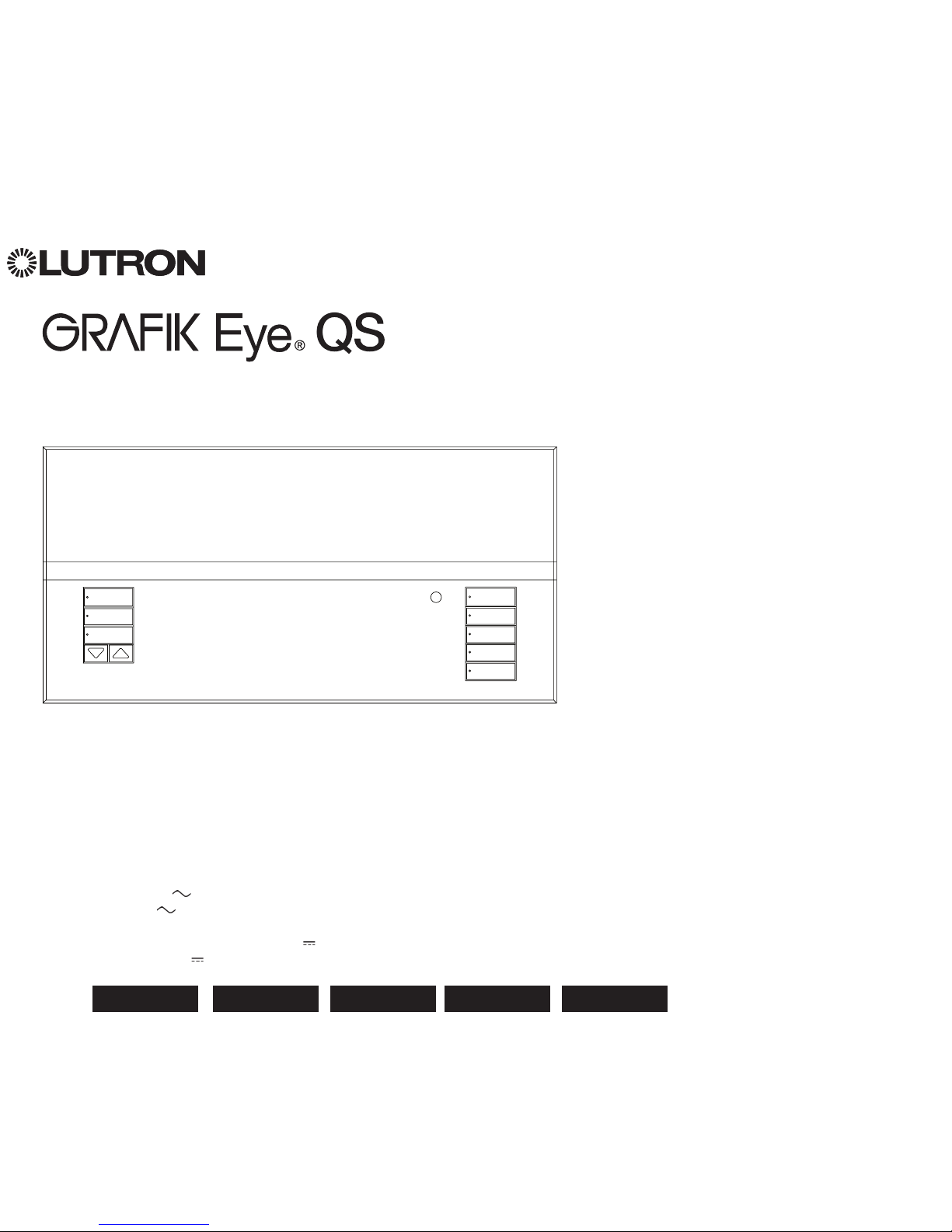
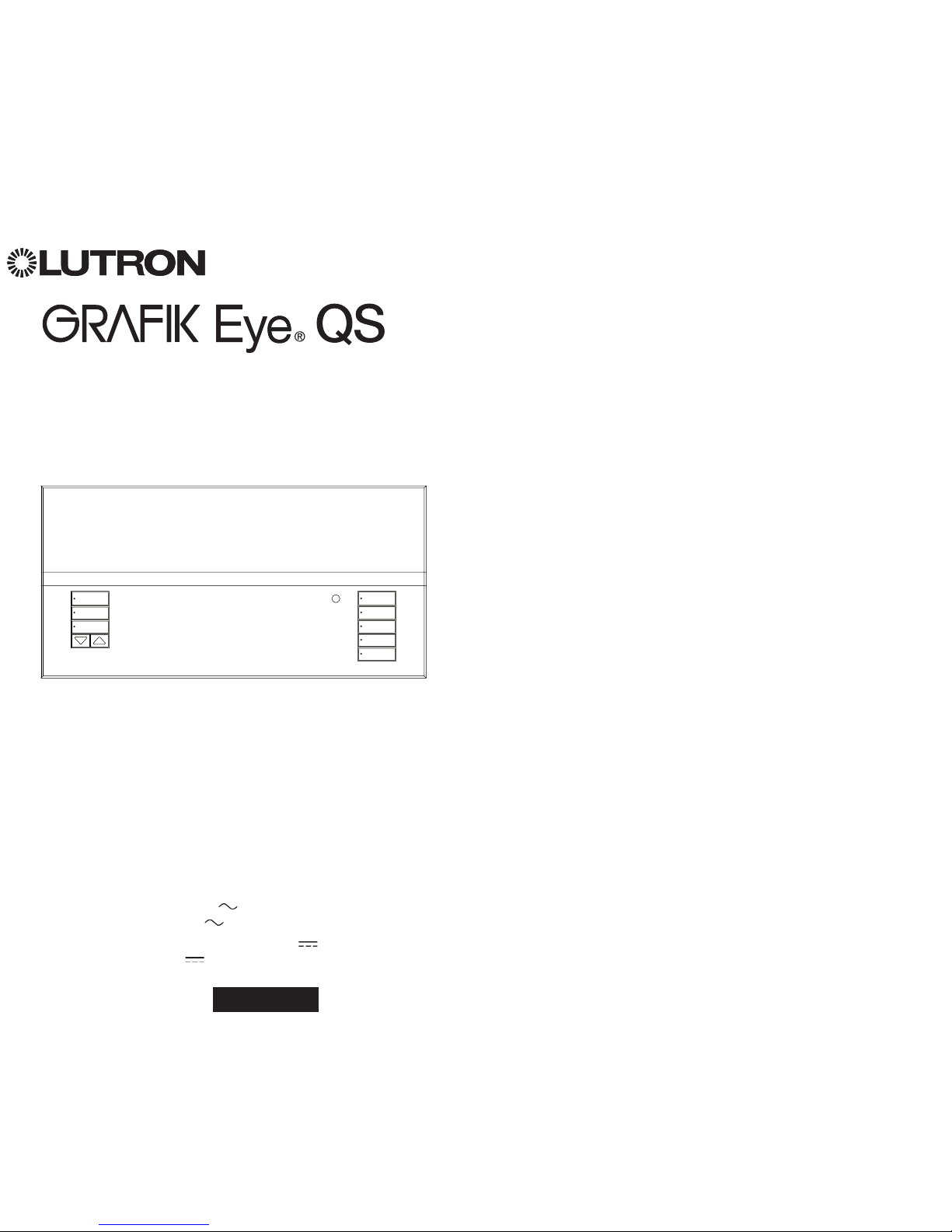
The GRAFIK Eye QS with DALI control unit allows for control of both lights
and window treatments, without interfaces, using a single control unit.
Features include pushbutton scene recall, info screen that displays energy
savings and status, IR receiver, astronomic timeclock, contact closure input,
and engravable backlit buttons that are easy to find and operate. The built-in
DALI bus link can control up to 64 DALI devices.
Model Numbers: QSGRK-6D, QSGRK-8D, QSGRK-16D
QSGR-6D, QSGR-8D, QSGR-16D
QSGRM-6D, QSGRM-8D, QSGRM-16D
Ratings: 100 - 240 V 50/60 Hz 100 mA
CE 230 V 50/60 Hz 100 mA
Output: PELV (Class 2: USA) supply 24 V 150 mA
DALI Link: 18 V 250 mA
Contents
Features and Functions. . . . . . . . . . . . . . . . . . . . . . . 2
Wiring the GRAFIK Eye® QS with DALI
Overview of Line Voltage/Mains
and DALI Wiring . . . . . . . . . . . . . . . . . . . . . . . . . 3
Line Voltage Wiring Details. . . . . . . . . . . . . . . . . . 4
DALI Bus Wiring Details . . . . . . . . . . . . . . . . . . . . 5
Overview of PELV (Class 2: USA) Wiring . . . . . . . 6
QS Link Control Wiring Details. . . . . . . . . . . . . . . 7
Completing Installation . . . . . . . . . . . . . . . . . . 8
Programming Mode . . . . . . . . . . . . . . . . . . . . . . . 9
Wireless Mode. . . . . . . . . . . . . . . . . . . . . . . . .10
Zone Setup . . . . . . . . . . . . . . . . . . . . . . . . . . . . . . 11
DALI Setup Overview: Build System . . . . . . . . . 12
DALI Setup . . . . . . . . . . . . . . . . . . . . . . . . . . . . . . 13
Associating Wireless Occupancy Sensors . .14
Occupancy Sensor Setup: Scene Mode . . . . . 15
Associating Wireless Daylight Sensors . . . . .16
Daylight Sensor Setup
Mode Assignment . . . . . . . . . . . . . . . . . . . . . . . . 17
Zone Mode . . . . . . . . . . . . . . . . . . . . . . . . . . . . . 18
Group Mode . . . . . . . . . . . . . . . . . . . . . . . . . . . . 19
Scene Setup . . . . . . . . . . . . . . . . . . . . . . . . . . . . . 21
Troubleshooting . . . . . . . . . . . . . . . . . . . . . . .22
Troubleshooting: DALI Functions . . . . . . . . . .23
Warranty, Contact Information . . . . . . . . . . . .24
For additional information, see the complete
installation and operation guide at
www.lutron.com/qs
English
Español Italiano
Français Deutsch
OK
1 2
3
4
5
69 10
11 12
13
14
7
815 16
9-16
1-8
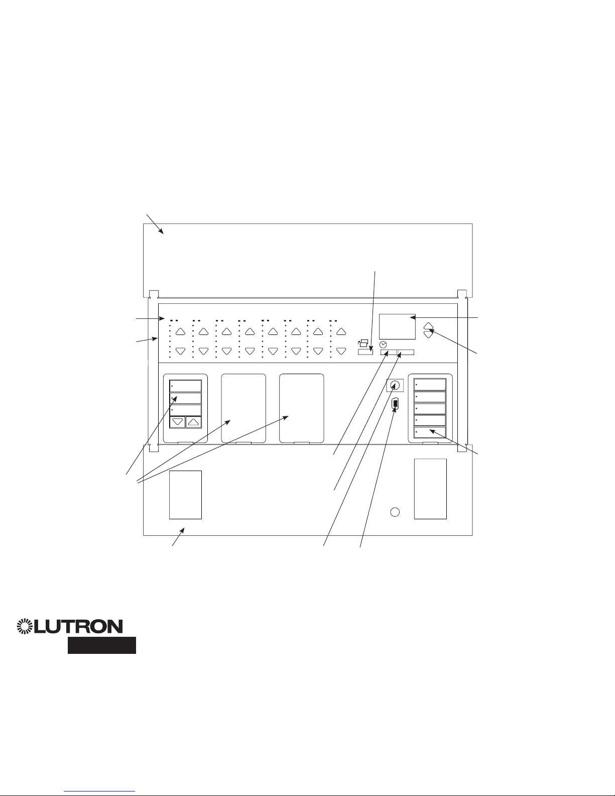
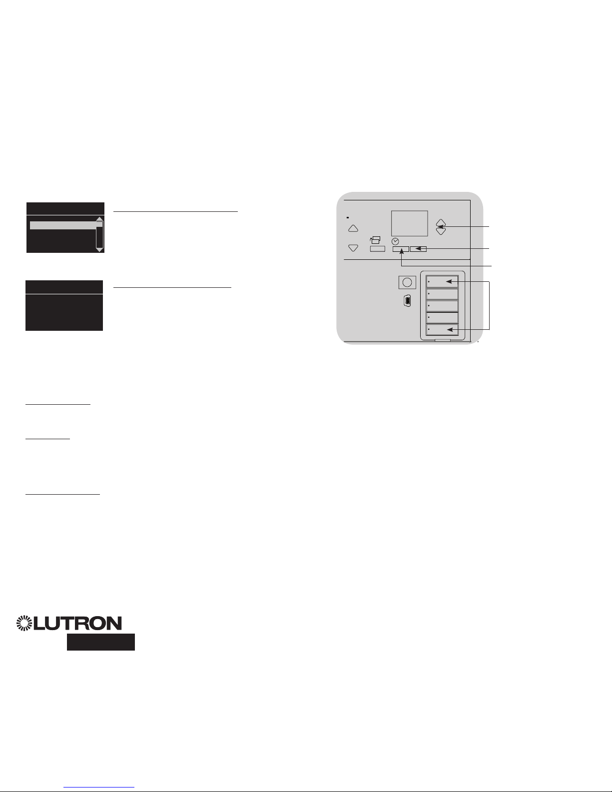
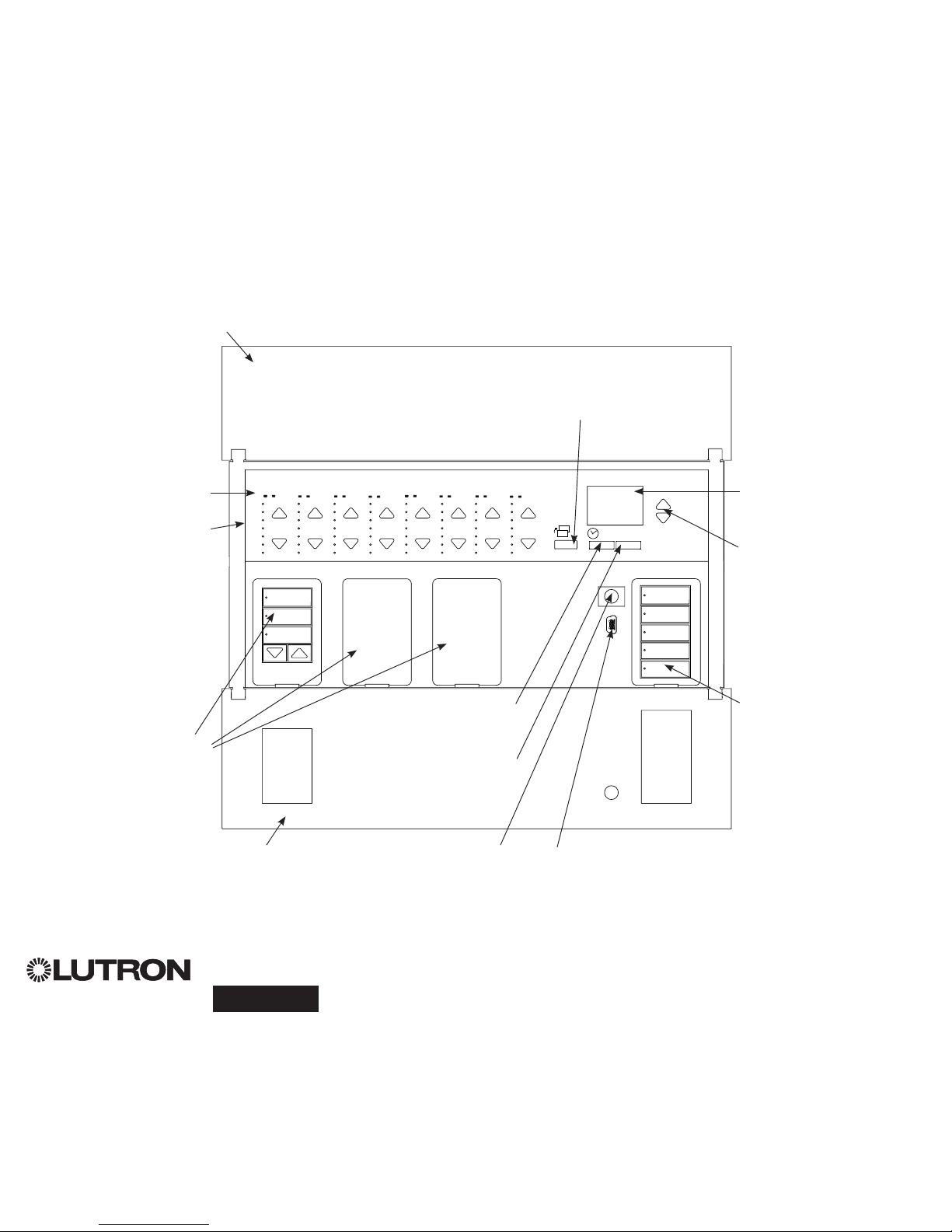
Info screen
Displays status or
programming functions
Scene buttons
With integral scene
indicator LEDs
Optional Shade
(window treatment) button
groups
Preset and raise/lower
buttons with integral LEDs
(maximum of 3 button
groups)
Zone numbers
Zone raise/lower buttons
Zone LEDs display current
lighting zone levels
Timeclock button
Displays current
timeclock info
OK button
Used for programming,
fade time
Infrared receiver
For handheld remote use
Master buttons
Temporarily raise and lower
lighting levels on unit
USB type mini B
For programming via PC
{
Hinged faceplate
Hinged faceplate
Features and Functions of the GRAFIK Eye® QS with DALI
Page button
Switches between displaying
zones 1 to 8 and 9 to 16 on
16-zone unit
Note: 6-zone control unit will show only zones 1 through 6.
®
GRAFIK Eye® QS with DALI Quick Installation and Operation Guide 2
For additional information, see the complete installation and operation guide at www.lutron.com/qs
®
GRAFIK Eye® QS with DALI Quick Installation and Operation Guide 3
For additional information, see the complete installation and operation guide at www.lutron.com/qs
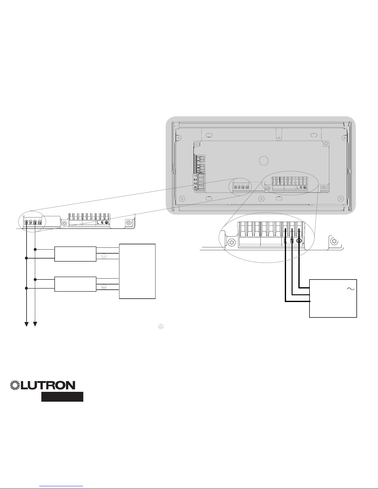
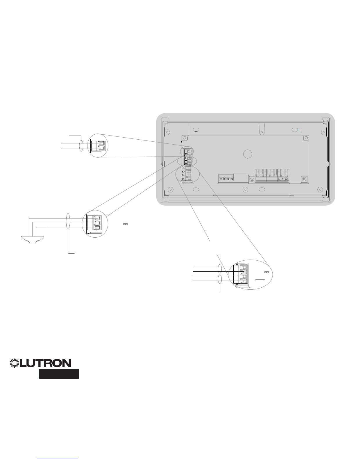
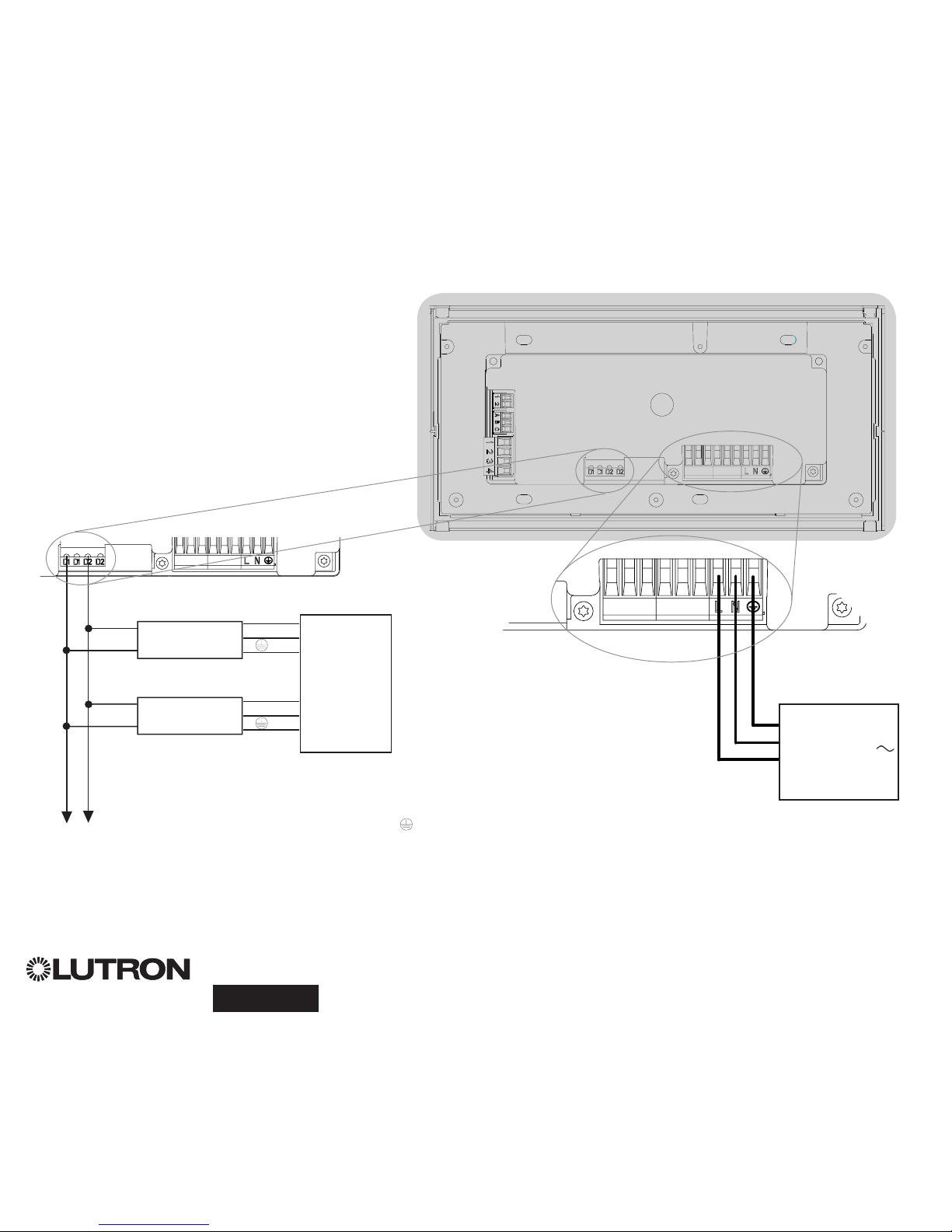
Wiring the GRAFIK Eye® QS with DALI:
Overview of Line Voltage/Mains and DALI Wiring
4,0 mm2 (12 AWG)
each terminal
100 – 240 V
50 / 60 Hz
Distribution
Panel
Line Voltage/Mains
Cables and Load Wiring
D2
D1
D2
D1
To additional DALI
devices
DALI Bus Wiring
(See page 5 for complete wiring
specification)
Two 1,5 mm2 (16 AWG)
each terminal
DALI devices: ballasts,
drivers, or interfaces
Two D1 and two D2 connections are
provided for ease of wiring, and to
provide two connecting points; there is
only one DALI link on the unit.
Note: Ballasts and other DALI devices
must NOT obtain power from a line
voltage output on the GRAFIK Eye QS
with DALI.
Distribution
Panel
L
N
L
N
Terminal labels:
L: Hot/Live
N: Neutral
: Ground
Wiring the GRAFIK Eye® QS with DALI:
Line Voltage Wiring Details
• Use properly certified cable for all line
voltage/mains cables.
• Proper short-circuit and overload
protection must be provided at the
distribution panel.
• Install in accordance with all local and
national electrical codes.
• PELV (Class 2: USA) terminals may be
temporarily unplugged for ease of IR,
occupancy sensor, and control wiring.
• Notice: Risk of damage to unit. Do not
connect line voltage/mains cable to PELV
(Class 2: USA) terminals.
Step 1: Install wallbox. Mount an 89 mm
(3,5 in) deep 4-gang U.S. wallbox on a
dry, flat indoor surface that is accessible
and allows for system programming and
operation. Allow at least 110 mm (4,5 in)
clearance above and below the faceplate
to ensure proper heat dissipation. Allow
25 mm (1 in) for faceplate overhang on
all sides.
Note: 4-gang wallbox available from
Lutron; P/N 241400.
Step 2: Check control unit wiring.
•
Earth/ground terminal connection must
be made as shown in wiring diagrams
(see page 3).
•
Do not mix different load types on the
same zone.
• Follow all local and national electrical
codes when installing PELV (Class 2:
USA) wiring with line voltage/mains wiring.
WARNING! Shock hazard. May
result in serious injury or death.
Always turn off circuit breaker or
remove main fuse from power
line before doing any work.
Before connecting the loads to
the GRAFIK Eye QS with DALI
control unit, test the loads for
short-circuits.
Step 3: Connect line voltage and loads
to control unit.
• Strip 8 mm (5/16 in) of insulation off the
line voltage/mains cables in the wallbox.
• Connect the line voltage/mains, ground,
and load wires to the appropriate
terminals on the back of the control unit.
L: Hot/Live
N: Neutral
: Ground
The recommended installation torque is
0,6 N∙m (5,0 in∙lbs) for line voltage/mains
connections and 0,6 N∙m (5,0 in∙lbs) for
the earth/ground connection.
Notice: Risk of damage to unit.
GRAFIK Eye QS with DALI control
units must be in stalled by a qual i fied
electrician in accordance with all applicable reg u la tions and building codes.
Im prop er wiring can result in dam age to
control units or oth er equipment.
Note: To avoid over heat ing and possi ble damage to equipment, do not
install control units to dim re cep ta cles,
mo tor-op erated ap pli ances, or flu o rescent lighting not equipped with DALI
electron ic dim ming ballasts, or other
DALI devices approved for your location.
Control units are de signed for res i den tial
and commercial use, for indoor use only.
LUTRON
LUTRON
Faceplate overhangs
wallbox on all sides;
allow 25 mm (1 in)
110 mm
(4,5 in)
8 mm
(5/16 in)
®
GRAFIK Eye® QS with DALI Quick Installation and Operation Guide 4
For additional information, see the complete installation and operation guide at www.lutron.com/qs
®
GRAFIK Eye® QS with DALI Quick Installation and Operation Guide 5
For additional information, see the complete installation and operation guide at www.lutron.com/qs
DALI bus wiring may be considered
NEC® Class 1 or PELV (Class 2: USA).
• NEC® Class 1: DALI bus wiring may be
run in the same conduit as mains voltage
wiring to fixtures.
• PELV (Class 2: USA): DALI bus wiring
must be separated from all mains and
NEC® Class 1 wiring.
• Consult applicable national and local
codes for compliance.
• Lutron recommends using two different
colours for D1 and D2 (DALI bus) wires.
This will prevent wiring mistakes in
junction boxes where several different
DALI bus wires combine. Use the
following instructions for wiring the DALI
bus.
• Each DALI link can have only 1 GRAFIK
Eye QS with DALI connected to it. No
additional DALI bus supplies can be on
the link.
• Up to 64 DALI devices can be connected
to the DALI link.
• No other devices may be connected to
the DALI link.
WARNING! Shock hazard.
May result in serious injury or
death.
Do not wire live. Interrupt
power via circuit breaker before
wiring and servicing the DALI bus
supply.
Step 1: Use the wire size chart at right to
determine which wire size to use based
on the length of the DALI bus.
Step 2: Wire the DALI bus from terminal
D1 and terminal D2 to all DALI devices.
Step 3: Separate DALI wiring from the
mains wiring. If wiring the DALI bus as
PELV (Class 2: USA), maintain proper
separation from mains and NEC® Class 1
wiring.
Step 4: Turn on circuit breaker to
energise.
DALI Bus
18 V
250 mA
Wiring the GRAFIK Eye® QS with DALI:
DALI Bus Wiring Details
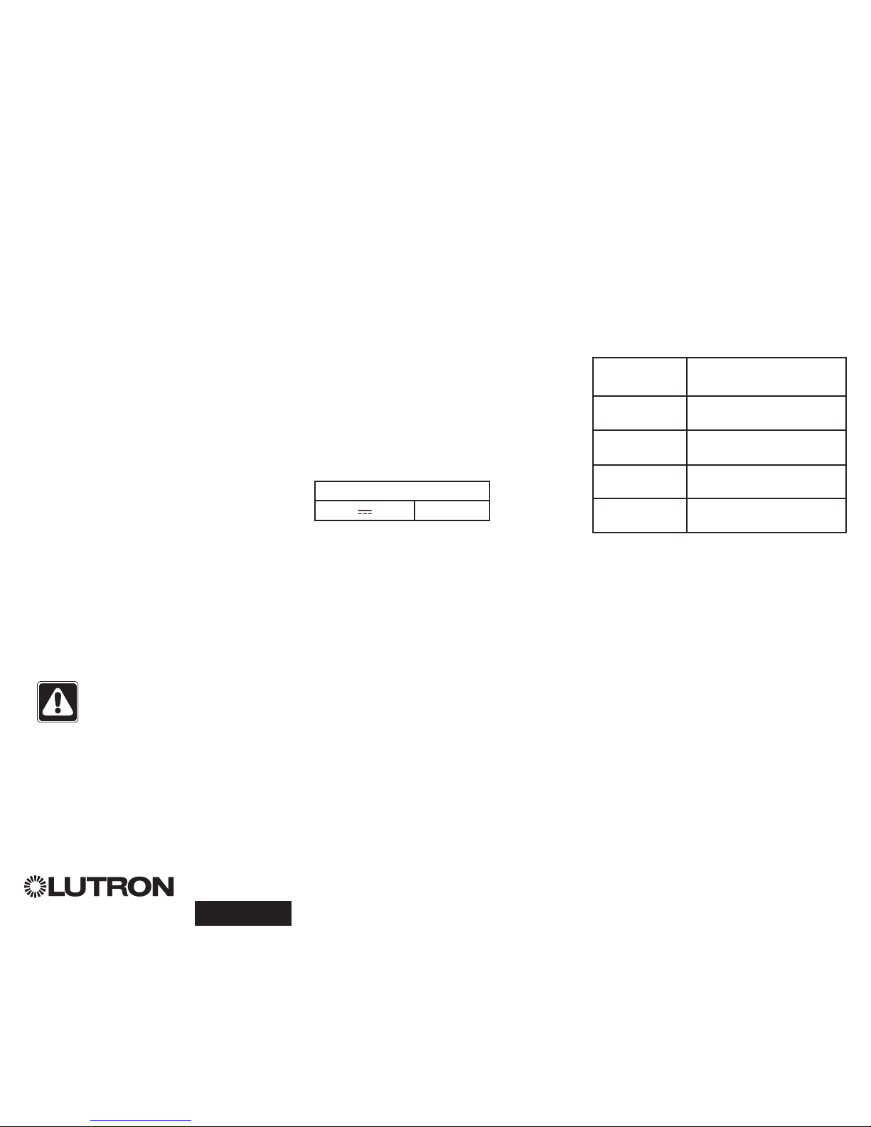
Wiring Size and Bus Length
DALI bus wires D1 and D2 are not
polarity sensitive. DALI bus length is
limited by the wire gauge used for D1 and
D2 as follows:
Wire Gauge Maximum DALI Bus
Length
4,0 mm
2
12 AWG
671 m
2 200 ft
2,5 mm
2
14 AWG
427 m
1 400 ft
1,5 mm
2
16 AWG
275 m
900 ft
1,0 mm
2
18 AWG
175 m
570 ft
DALI bus wiring cables (1,5 mm2 /
16 AWG) are available from Lutron, part
numbers C-CBL-216-GR-1 (non-plenum)
and C-PCBL-216-CL-1 (plenum).
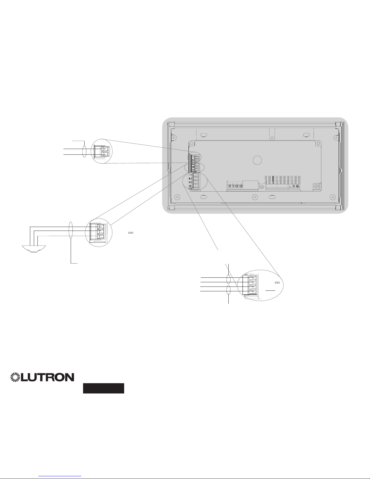
Contact Closure Input Wiring
For settings, see complete installation and
operation guide at www.lutron.com/qs.
1 2
A B C
N H 1 2 3 4 5 6
1 2 3 4
1 2
1 2
A B C
Note: Use appropriate wire connecting devices
as specified by local codes.
Example:
Occupancy sensor
(maximum 1)
1: COM
2: 24 V *
3: MUX
4: MUX
Control Wiring
Wiring the GRAFIK Eye® QS with DALI:
Overview of PELV (Class 2: USA) Wiring
IR Wiring
From external
IR connection
(by others)
1,0 mm2 (18 AWG)
each terminal
1,0 mm2 (18 AWG)
each terminal
1: IR DATA
2: IR COM
A: CCI SIG
B: 24 V
C: CCI COM
To control stations,
window treatments,
or other GRAFIK Eye
QS control units
Data (terminals 3 and 4):
Twisted, shielded pair 0,5 mm2 (22 AWG)
each terminal
Common and power (terminals 1 and 2):
Two 1,0 mm2 (18 AWG) each terminal
* Do not connect terminal 2
between any GRAFIK Eye QS
and any other power supply,
including another
GRAFIK Eye
QS. See complete installation
and operation guide at www.
lutron.com/qs. for detailed wiring
example.
®
GRAFIK Eye® QS with DALI Quick Installation and Operation Guide 6
For additional information, see the complete installation and operation guide at www.lutron.com/qs
• System communication uses PELV (Class 2: USA)
wiring.
• Follow all local and national electrical codes when
installing PELV (Class 2: USA) wiring with line
voltage/mains wiring.
• Each terminal accepts up to two 1,0 mm2 (18 AWG)
wires.
• Total length of control link must not exceed
610 m (2 000 feet).
• Make all connections in the control unit’s wallbox.
• Wiring can be T-tapped or daisy-chained.
• Wire sizes:
- Two 1,0 mm2 (18 AWG) conductors for control
power.
- One twisted, shielded pair of 0,5 mm2 (22 AWG) for
data link.
- Cable is available from Lutron:
GRX-CBL-346S-500 (non-plenum) and
GRX-PCBL-346S-500 (plenum). Check
compatibility in your area.
• PELV (Class 2: USA) 24 V 150 mA.
QS smart
power
panel
LUTRON
LUTRON
LUTRONLUTRON
LUTRON
LUTRON
LUTRON
LUTRON
LUTRON
LUTRON
LUTRON
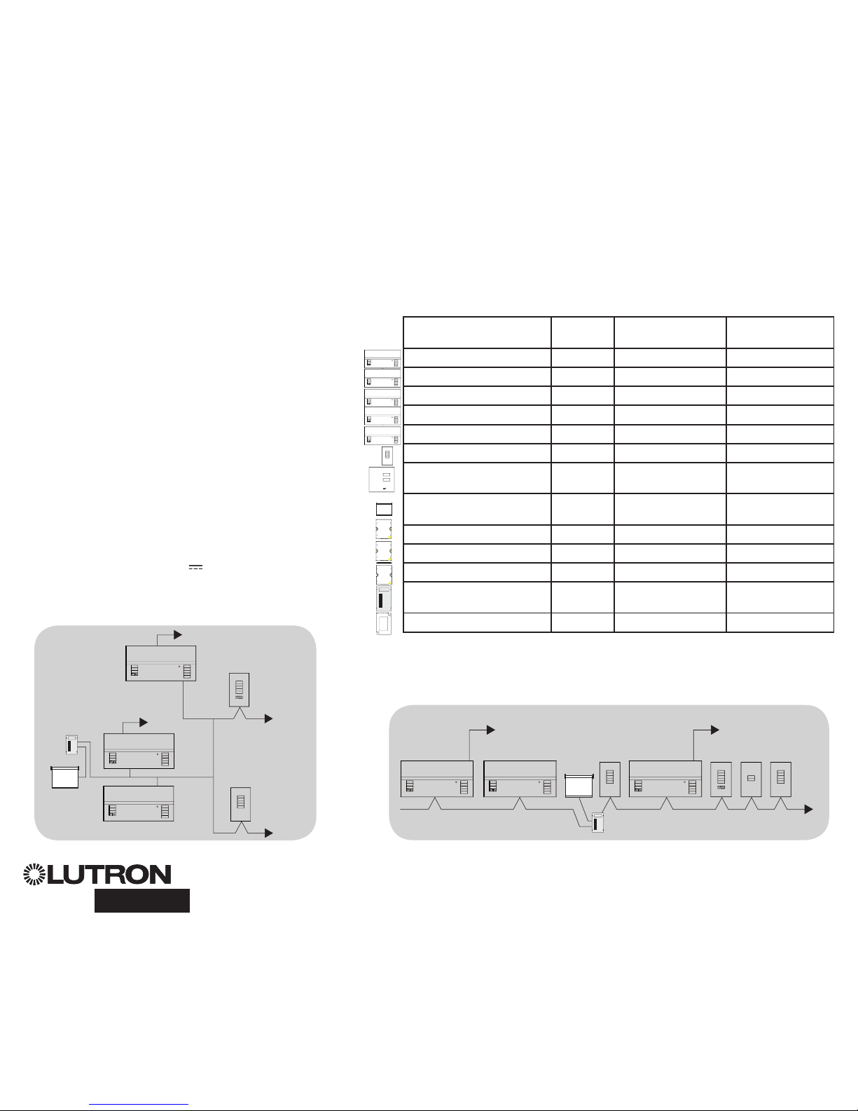
T-Tap Wiring Example
GRAFIK Eye QS
with DALI
Sivoia QS
seeTouch QS
Wiring the GRAFIK Eye® QS with DALI:
QS Link Control Wiring Details
To DALI link 1
To DALI link 2
System Limits
The QS wired communication link is limited to 100 devices or 100 zones. Please
note the zone count and power draw unit information in the following table.
QS Device Zone
Count
Power Draw Units
(supplied)
Power Draw
Units (consumed)
3-zone
GRAFIK Eye QS 3 3 0
4-zone
GRAFIK Eye QS 4 3 0
6-zone
GRAFIK Eye QS 6 3 0
8-zone
GRAFIK Eye QS 8 3 0
16-zone
GRAFIK Eye QS 16 3 0
seeTouch
® QS 0 0 1
International seeTouch
®
QS
0 0 1
Sivoia
® QS 1 0 (Refer to Spec.
Submittal)
Contact closure interface 5 0 3
Network interface 0 0 2
DMX interface 0 0 2
QS smart power panel 0 (Refer to Spec.
Submittal)
0
QS link power supply 0 8 0
LUTRON
LUTRON
LUTRONLUTRON
LUTRON
LUTRON
LUTRON
LUTRON
LUTRONLUTRON
LUTRON
LUTRON
LUTRON
LUTRON
LUTRON
LUTRON
LUTRON
LUTRON
LUTRONLUTRON
LUTRON
LUTRON
LUTRON
LUTRON
LUTRON
LUTRONLUTRON
LUTRON
LUTRON
GRAFIK Eye QS
with DALI
Sivoia
QS
seeTouch QS
Daisy-Chain Wiring Example
QS smart
power panel
To DALI link 2To DALI link 1
GRAFIK Eye QS
with DALI
LUTRON
LUTRON
LUTRONLUTRON
LUTRON
LUTRON
LUTRON
LUTRON
LUTRONLUTRON
LUTRON
LUTRON
LUTRON
LUTRON
LUTRONLUTRON
LUTRON
LUTRON
®
GRAFIK Eye® QS with DALI Quick Installation and Operation Guide 7
For additional information, see the complete installation and operation guide at www.lutron.com/qs
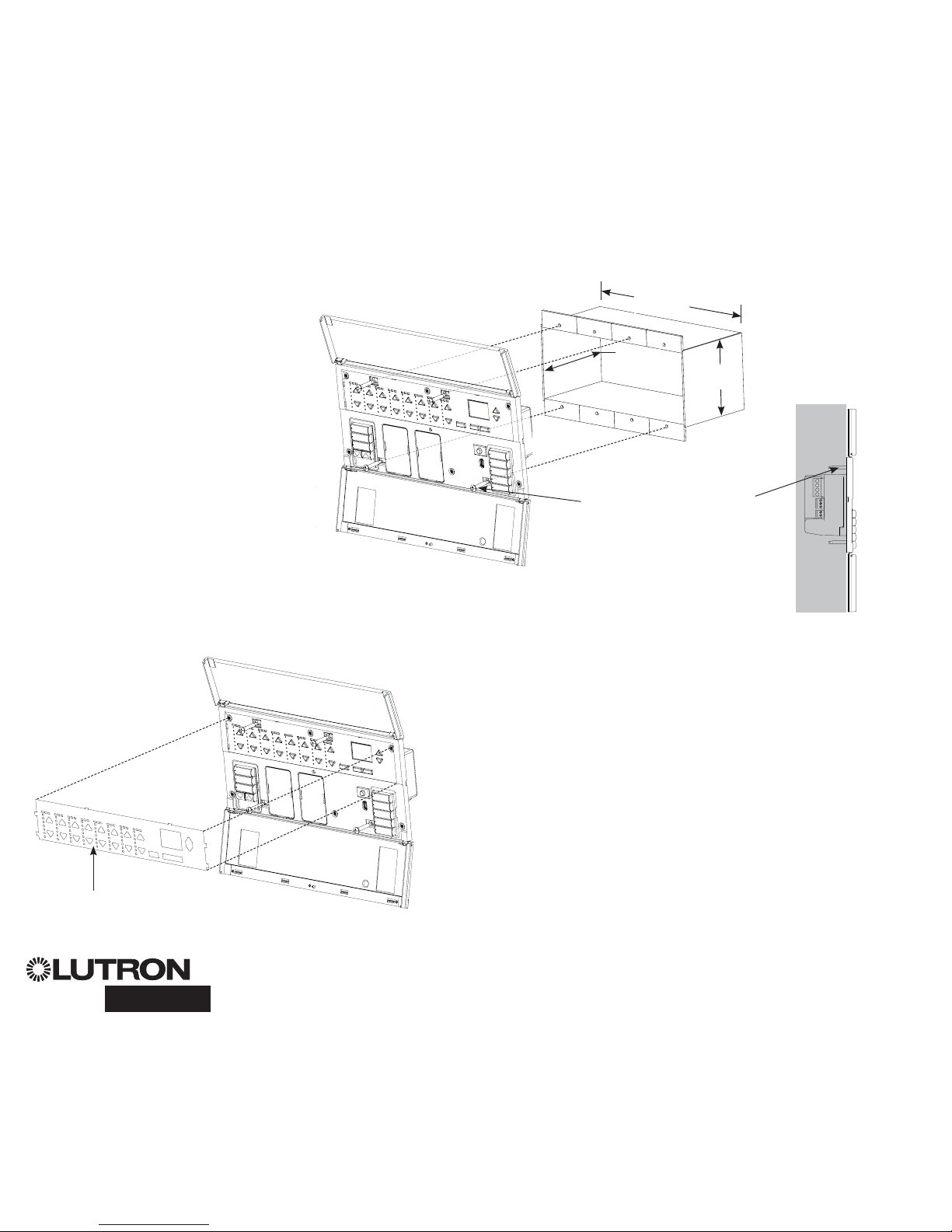
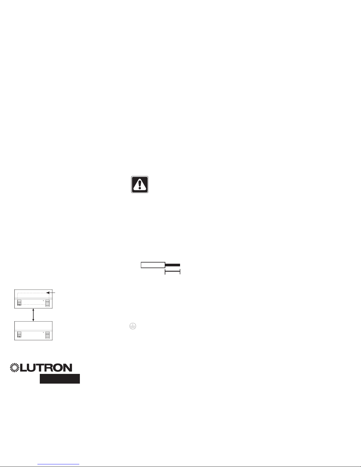
Completing Installation of the GRAFIK Eye® QS with DALI
1. Mount the control unit in the wallbox as
shown using the four screws pro vid ed.
Note: Follow all local and national
electrical codes when installing PELV
(Class 2: USA) wiring with line voltage/
mains wiring.
2. Verify installation:
• Restore power.
• Press the top scene button. The LED will
light.
•
Press the zone raise or lower button.
Make sure the control unit is dimming all
connected loads.
3. Apply the protective overlay to the control
unit. See the complete installation and
operation guide at www.lutron.com for
instructions for naming zones.
Note: When tightening mounting
screws, make sure that the hinged
cover and faceplate will open fully,
as shown.
Wall
7,9 in
(200 mm)
3,5 in
(87 mm)
3,75 in
(95 mm)
Protective overlay
(apply after installation)
®
GRAFIK Eye® QS with DALI Quick Installation and Operation Guide 8
For additional information, see the complete installation and operation guide at www.lutron.com/qs
Entering and Exiting Programming Mode
To enter programming mode:
Press and hold the top and bottom scene
buttons simultaneously for 3 seconds. The
LEDs in the scene buttons will scroll from
top to bottom, confirming that you are in
programming mode, and the info screen will
display the main menu.
To exit programming mode:
Press and hold the top and bottom scene
buttons simultaneously for 3 seconds. The
info screen will go to Scene 1.
Navigating Menus in Programming Mode
Master Buttons
The Master buttons allow you to move through the menu
choices. The current choice is highlighted on the info screen.
OK Button
The OK button chooses the current highlighted menu choice.
This will either take you to the next menu or accept a setting you
have selected. When the screen displays a Yes/No question, the
OK button is “Yes”.
Timeclock Button
The timeclock button functions as a “back” button during
programming mode. Pressing the timeclock button takes you
back one step in the current menu. Pressing it repeatedly
will eventually return you to the main menu, but will not exit
programming mode. When the screen displays a Yes/No
question, the Timeclock button is “No”.
Programming Mode
OK
16
9-16
1-8
Press and hold the top and
bottom buttons for 3 seconds
to enter or exit programming
mode
Master buttons
OK button
Timeclock (back) button
Main menu
Scene setup
Timeclock
Scene 1
Fade time
3 seconds
®
GRAFIK Eye® QS with DALI Quick Installation and Operation Guide 9
For additional information, see the complete installation and operation guide at www.lutron.com/qs

®
GRAFIK Eye® QS with DALI Quick Installation and Operation Guide 10
For additional information, see the complete installation and operation guide at www.lutron.com/qs
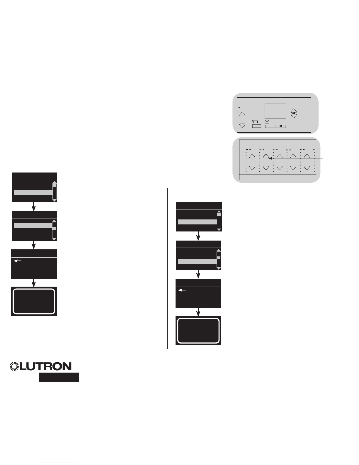
Wireless Mode
Many models of the GRAFIK Eye® QS support wireless communication with other
Lutron products. This feature allows for easy integration of wireless sensors, keypads,
remotes, and window treatments for single-room wireless applications, as well as
compatibility with other Lutron wireless systems.
Units supporting wireless communication have model numbers beginning with QSGRJ,
QSGRK, or QSGRM.
The wireless feature of the GRAFIK Eye QS Wireless control unit has three (3) modes of
operation.
• Disabled: Use for wired-only systems.
• Enabled: The GRAFIK Eye QS Wireless control unit will respond to any programming
commands from nearby Lutron QS wireless (and compatible) products.
• Ignore Programming (default): The GRAFIK Eye QS Wireless control unit will only
respond to normal operation commands from wireless devices programmed while in
Enabled mode.
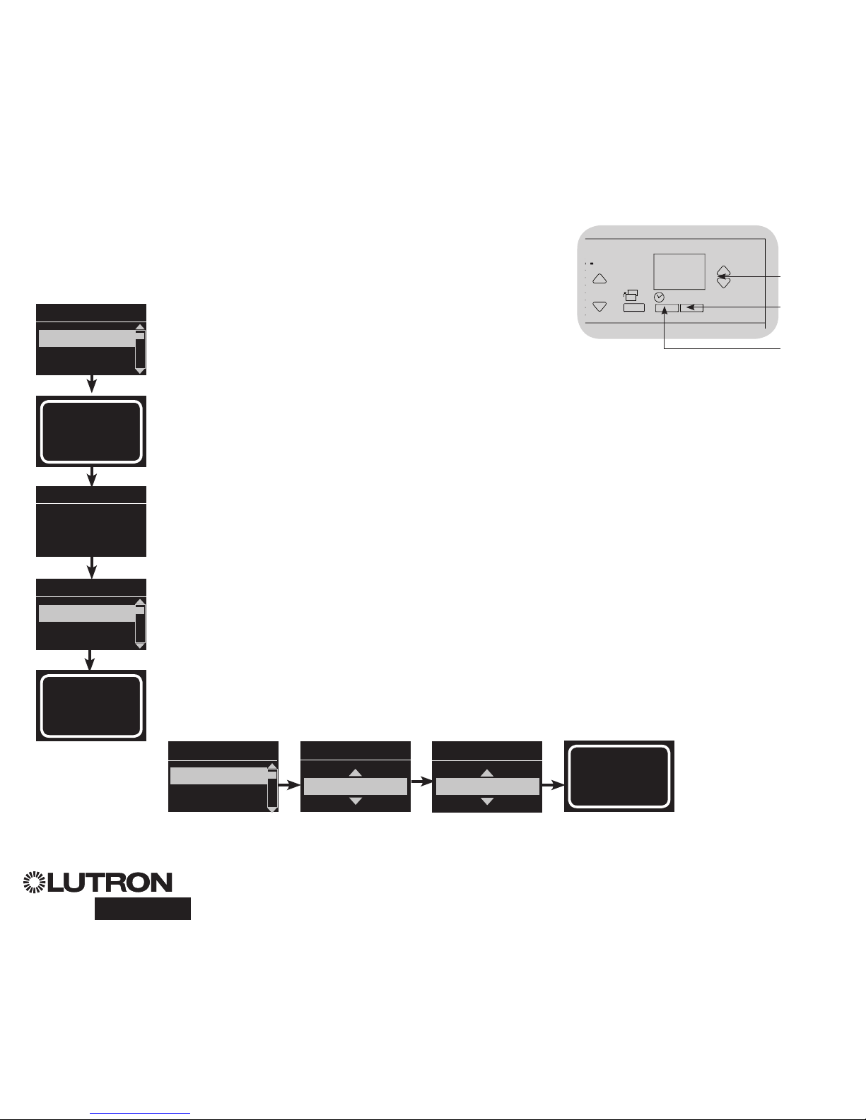
To change the wireless mode of the GRAFIK Eye QS wireless control unit:
1. Enter programming mode (see page 9).
2. Use the Master buttons to highlight “Wireless Mode” and press
the OK button to accept.
3. Use the Master buttons to highlight the desired wireless mode,
and press the OK button to accept.
4. The info screen will display a confirming “Saved” message.
5. Exit programming mode (see page 9).
Notes
• The wireless signal has a range of 10 m (30 feet) through
standard construction.
Wireless Mode
Enabled
Saved
Saved
Main menu
Shade labels
Wireless Mode
OK
16
9-16
1-8
Master
buttons
OK
button
Timeclock
(back) button
®
GRAFIK Eye® QS with DALI Quick Installation and Operation Guide 11
For additional information, see the complete installation and operation guide at www.lutron.com/qs
Assign Load Types
Load types supported by the GRAFIK Eye® QS with DALI:
• Digital load
• DMX
• RGB/CMY DMX
• Non-dim digital
Note: For all DMX or RGB/CMY DMX lighting, an external
DMX interface (such as the QSE-CI-DMX) must be
used with the control unit.
1. Enter programming mode (see page
9).
2. Use the Master buttons to highlight
“Zone setup” and press the
OK button to accept.
3. Use the Master buttons to highlight
“Load type”. Press the OK button to
accept.
4. Use the zone raise/lower buttons to
choose the load type for that zone.
Press the OK button to accept.
5. The info screen will confirm that your
load type has been saved.
6. Exit programming mode (see page 9).
Zone Setup
OK
16
9-16
1-8
Master
buttons
OK button
Main menu
CCI Mode
Zone setup
OK
1 2
3
4
5
69 10
11 12
13
14
7
815 16
9-16
1-8
Use the
zone
raise/lower
buttons to
choose the
load type for
that zone.
Zone Setup
Non-Dim Load Type
Load Type
Set zones
Saved
Load Type
Assign Non-Dim Load Type
Zones assigned to non-dim loads have three available configurations:
• LOFO: Last On, First Off
• FOFO: First On, First Off
• FOLO: First On, Last Off
Scenes made up of both dim and non-dim
load types will toggle the non-dim loads
before the dim loads in a “First” on/off
configuration, and after the dim loads in a
“Last” on/off configuration.
1. Enter programming mode (see page 9).
2. Use the Master buttons to highlight “Zone
setup” and press the OK button to accept.
3. Use the Master buttons to highlight “Non-Dim
Load type”. Press the OK button to accept.
4. Use the zone raise/lower buttons to choose
the non-dim load type for that zone. (Zones
not programmed as non-dim will be displayed
as Unaffected.) Press the OK button to
accept.
5. The info screen will confirm that your load
type has been saved.
6. Exit programming mode (see page 9).
Main menu
CCI Mode
Zone setup
Zone Setup
Load Type
Load Type
Set zones
Saved
Non-Dim Load Type
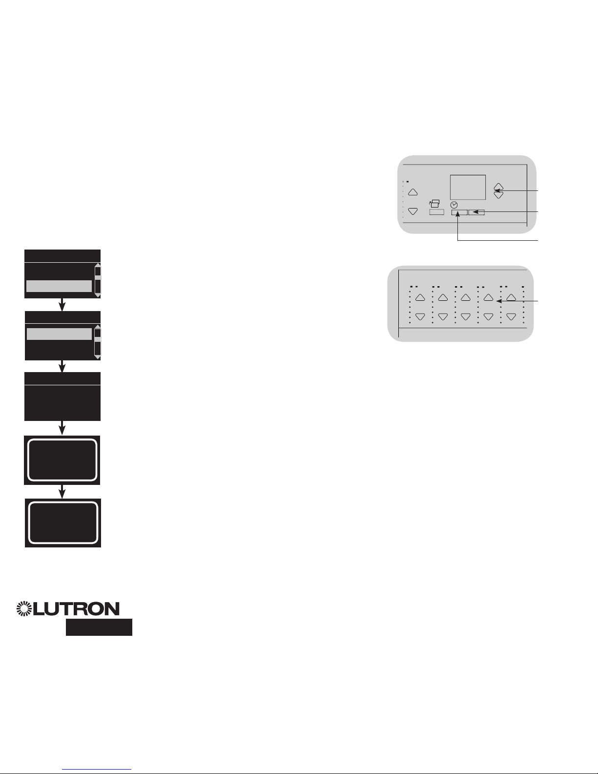
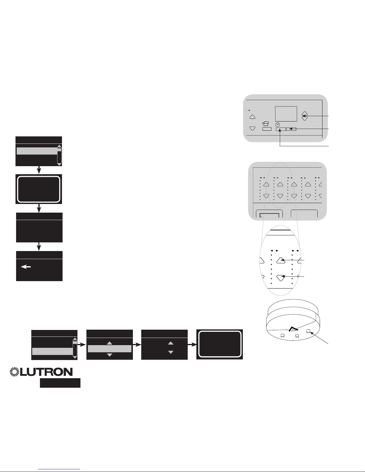
DALI Setup Overview
After DALI devices are wired and powered, they must be reset and addressed so the
system can control them. The “Build System” command automates this process, as
shown below.
Note: All existing DALI programming will be deleted when the “Build System”
command is run.
Build System
1. Enter programming mode (see page 9).
2. Use the Master buttons to highlight “DALI” and press the
OK button to accept.
3. Use the Master buttons to highlight “Build system” and press
the OK button to accept.
4. Press the OK button to erase all current programming, reset
and address DALI devices, and find sensors on the system.
5. Exit programming mode (see page 9).
Note: After running “Build System”, Zone 4 will control all DALI
devices for diagnostics and verification of wiring. (This feature
is disabled once any of the addressed devices are assigned
to a zone on the GRAFIK Eye QS.) Use the Zone 4 raise/lower
buttons to verify that all devices are correctly addressed. If a
device does not respond, repeat the “Build System” command
and/or check the wiring.
Main menu
Zone setup
DALI
Assign zones
Build system
Erase digital load
Programming?
Build system
DALI
OK
1 2
3
4
5
69 10
11 12
13
14
7
815 16
9-16
1-8
Use Zone 4
raise/lower
buttons
to verify
all DALI
devices
have been
addressed.
Searching...
x
Found
x Loads
Found
OK
16
9-16
1-8
Master
buttons
OK
button
Timeclock
(back) button
®
GRAFIK Eye® QS with DALI Quick Installation and Operation Guide 12
For additional information, see the complete installation and operation guide at www.lutron.com/qs
®
GRAFIK Eye® QS with DALI Quick Installation and Operation Guide 13
For additional information, see the complete installation and operation guide at www.lutron.com/qs
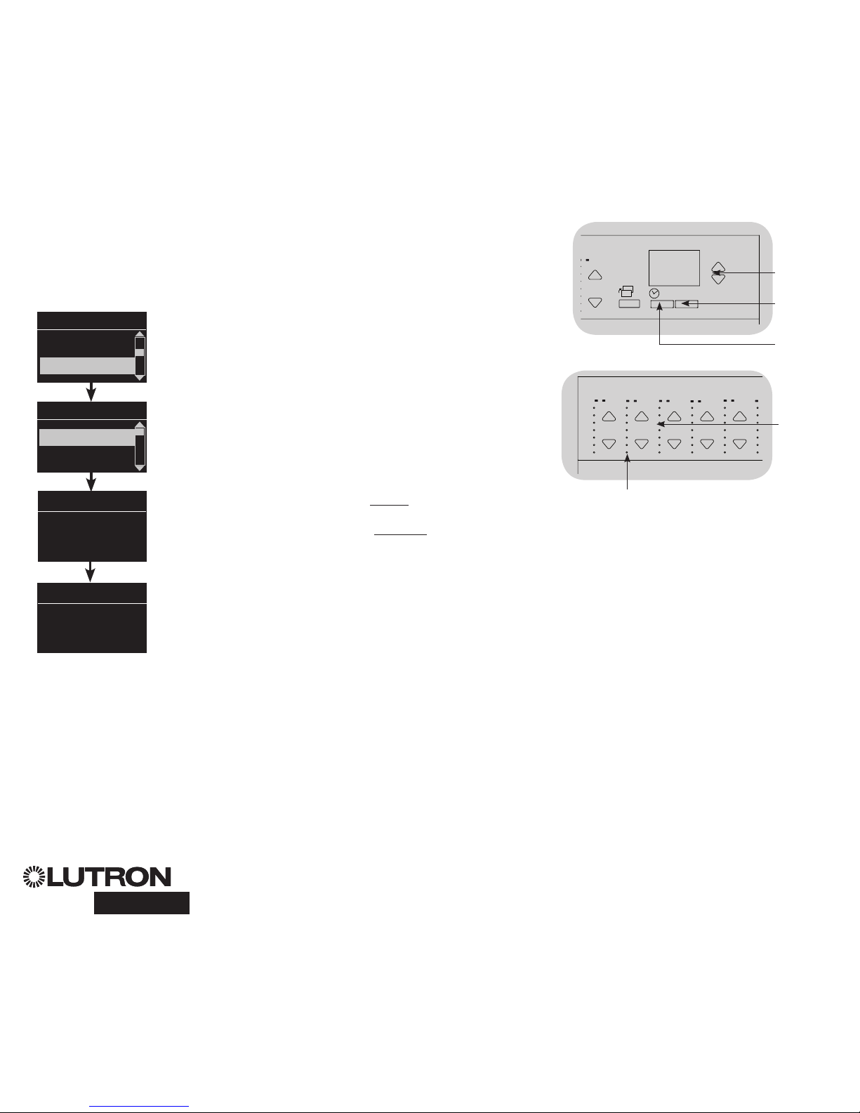
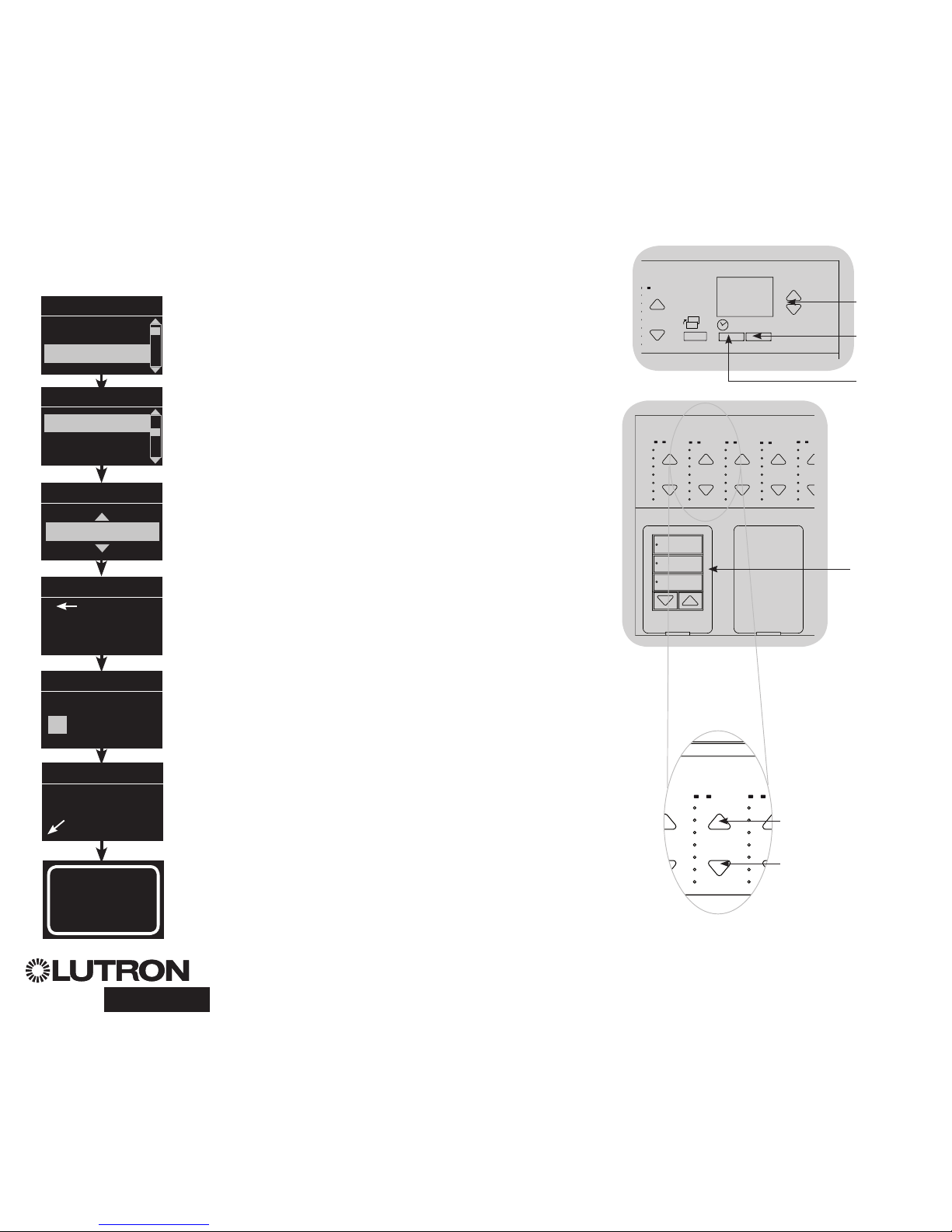
DALI Setup
Assign/Unassign a DALI Device to a Zone (Zone setup)
DALI devices must be addressed on the system (see previous page) before assigning
or unassigning to a zone.
1. Enter programming mode (see page 9).
2. Use the Master buttons to highlight “DALI” and press the OK
button to accept.
3. Use the Master buttons to highlight “Assign zones” and press
the OK button to accept.
4. Use the Master buttons to scroll through the DALI devices on
the link. The selected device will flash, and the info screen
will display the device number and the number of devices on
the link. If the device is currently assigned to a zone, the zone
number will display at the bottom of the screen and the LEDs
for the zone will go on; otherwise, the info screen will display
“*Unassigned*”.
• Press the zone raise button to assign the device to that
zone.
• Press the zone lower button to unassign the device to that
zone.
5. Press the timeclock (back) button to return to the DALI menu.
DALI devices will return to normal levels.
6. Exit programming mode (see page 9).
Notes
Devices that were previously assigned to a zone will be
removed from the old zone and assigned to the new zone
(each device can be assigned to only 1 zone at a time).
Devices can be assigned only to zones set to DALI load type.
Refer to page 11 for instructions on changing load type.
OK
1 2
3
4
5
69 10
11 12
13
14
7
815 16
9-16
1-8
Use the
zone raise
or lower
button to
assign or
unassign
a DALI
device to
that zone.
Zone LEDs
Main menu
Zone setup
Zone setup
DALI
Address All
Assign zones
Assign zones
Ballast 2 / 23
Zone 3
DALI
Assign zones
Ballast 2 / 23
*Unassigned*
OK
16
9-16
1-8
Master
buttons
OK
button
Timeclock
(back) button
®
GRAFIK Eye® QS with DALI Quick Installation and Operation Guide 14
For additional information, see the complete installation and operation guide at www.lutron.com/qs
OK
1 2 3 4 5 6
Wireless Occupancy Sensor
“Talks” to GRAFIK Eye QS control
unit, activating scenes on the
GRAFIK Eye QS.
Lutron’s wireless Radio Powr SavrTM occupancy and vacancy sensors can
be associated with the GRAFIK Eye QS Wireless to activate scenes when
occupancy or vacancy is detected.
This section applies to installations where the GRAFIK Eye QS Wireless is
being used in a single-room wireless installation.
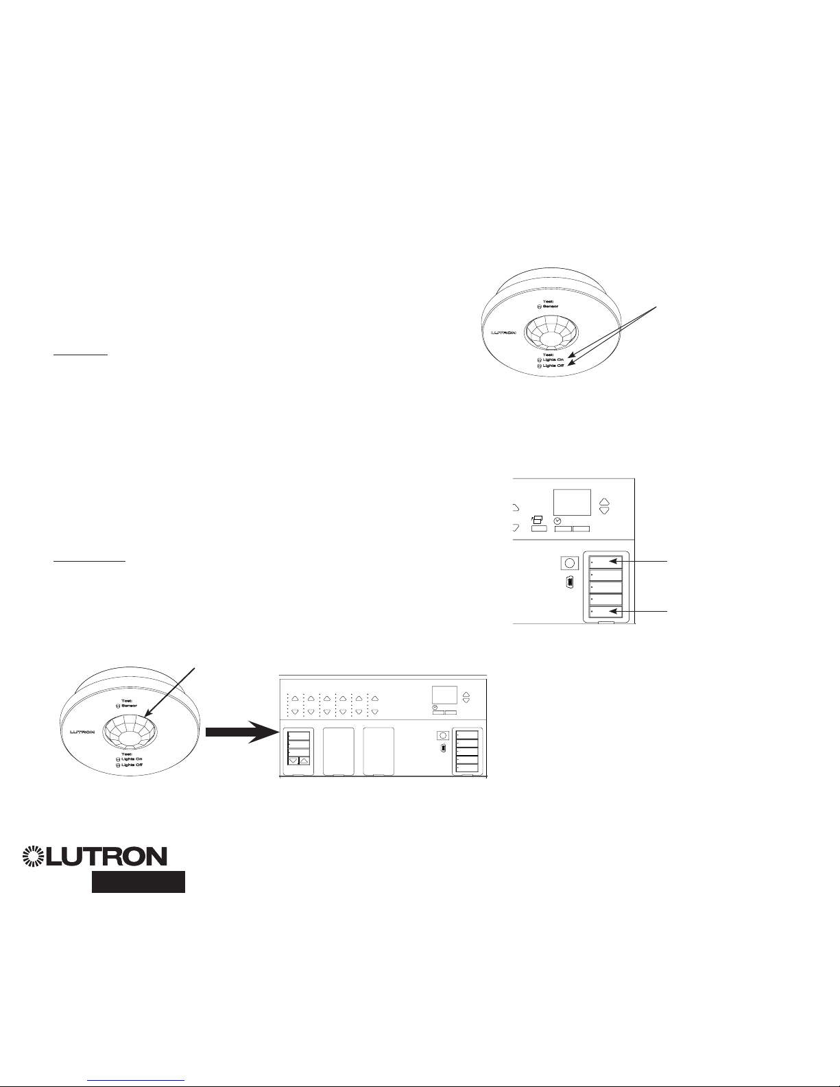
To associate wireless occupancy sensors and GRAFIK Eye QS control units:
1. Make sure the wireless mode of the GRAFIK Eye QS control unit is
“Enabled” (see page 10).
2. Press and hold the “Lights On” and “Lights Off” buttons on the front of
the occupancy/vacancy sensor simultaneously until the lens starts flashing
(about 3 seconds). The info screen on the GRAFIK Eye QS will display
“Occ Sensor Programming.”
3. Press and hold the top scene button of the GRAFIK Eye QS Wireless
control unit until the LEDs flash (about 3 seconds).
4. Return to the occupancy sensor. Press and hold the “Lights On” and
“Lights Off” buttons simultaneously until the lens stops flashing (about 3
seconds).
5. Test communication between the devices using the “Lights On” and “Lights
Off” buttons.
To disassociate wireless occupancy sensors and GRAFIK Eye control units:
Simply repeat the association steps, in the same order; press and hold the
bottom scene button on the GRAFIK Eye QS to disassociate.
Note: The wireless signal has a range of 10 m (30 feet) through standard
construction.
Associating Wireless Occupancy Sensors and GRAFIK Eye® QS Wireless Control Units
(for wireless enabled units only)
On the wireless occupancy
sensor, press and hold the
“Lights On” and “Lights Off”
buttons for 3 seconds to
begin or end association
or disassociation with the
GRAFIK Eye QS control unit.
Note: Pressing the “Lights
On” button initiates the
“occupied” action on the
GRAFIK Eye QS control
unit. Pressing the “Lights
Off” button initiates the
“unoccupied” action.
OK
9-16
1-8
On the GRAFIK Eye QS control unit,
press and hold the top scene button
for 3 seconds to associate, or press
and hold the bottom scene button for
3 seconds to disassociate with the
occupancy sensor.
Associate
OR
Disassociate
GRAFIK Eye QS Control Unit
“Listens” to wireless occupancy sensor,
so that the occupancy sensor activates
scenes on the GRAFIK Eye QS.
Lens
®
GRAFIK Eye® QS with DALI Quick Installation and Operation Guide 15
For additional information, see the complete installation and operation guide at www.lutron.com/qs
Occupancy Sensor Setup
Scene Mode
This step allows you to assign occupied and unoccupied scenes to up to four
occupancy sensors connected to the GRAFIK Eye® QS control unit.
Select Sensors
1. If not already done, select “Scene Mode” from the
Occupancy Sensor Setup menu.
2. Use the Master buttons to highlight “Setup” and press the
OK button to accept. The screen will display “Searching” while
the unit detects available occupancy sensors.
3. Use the Master buttons to scroll through the list of available
occupancy sensors. When the desired sensor is displayed,
press the OK button to select it. Then choose “Assign” or
“Unassign” from the following menu and press OK. A screen
will verify your choice has been completed. Repeat for
additional sensors.
Set Sensor Action
4. Press the Back button to return to the Occ Sensor screen.
Use the Master buttons to highlight “Actions” and press the
OK button to accept. By default, the occupied scene is set to
“No Action” and the unoccupied scene is set to “Scene Off”.
5. Use the Master buttons to highlight the scene you wish to
use for occupied status and press the OK button to accept.
Repeat for the scene you wish to use for unoccupied status.
Press the OK button to accept.
6. Exit programming mode (see page 9).
Note: If wireless sensors are not found, verify that they are
associated correctly (see page 14).
Saved
Saved
3 seconds
Occ Sensor
Setup
Actions
Occupied Scene
Scene 1
Unoccupied Scene
Scene Off
Occ Sensor
Labels
Setup
Sensor x/y
SN: xxxx-xxxx
Source: RF 1/n
Assignment
Unassign
Assign
Saved
*Assigned*
Saved
Searching
OK
16
9-16
1-8
Master
buttons
OK
button
Timeclock
(back) button
®
GRAFIK Eye® QS with DALI Quick Installation and Operation Guide 16
For additional information, see the complete installation and operation guide at www.lutron.com/qs
Lutron’s wireless Radio Powr SavrTM daylight sensors can be associated with the
GRAFIK Eye QS Wireless to adjust light levels when certain daylight levels are detected.
This section applies to installations where the GRAFIK Eye QS Wireless is being used in
a single-room wireless installation.
To associate wireless daylight sensors and GRAFIK Eye QS Wireless control units:
1. Make sure the wireless mode of the GRAFIK Eye QS control unit
is “Enabled” (see page 10).
Note: To properly save the wireless mode, exit and then re-enter
programming mode before associating wireless daylight
sensors.
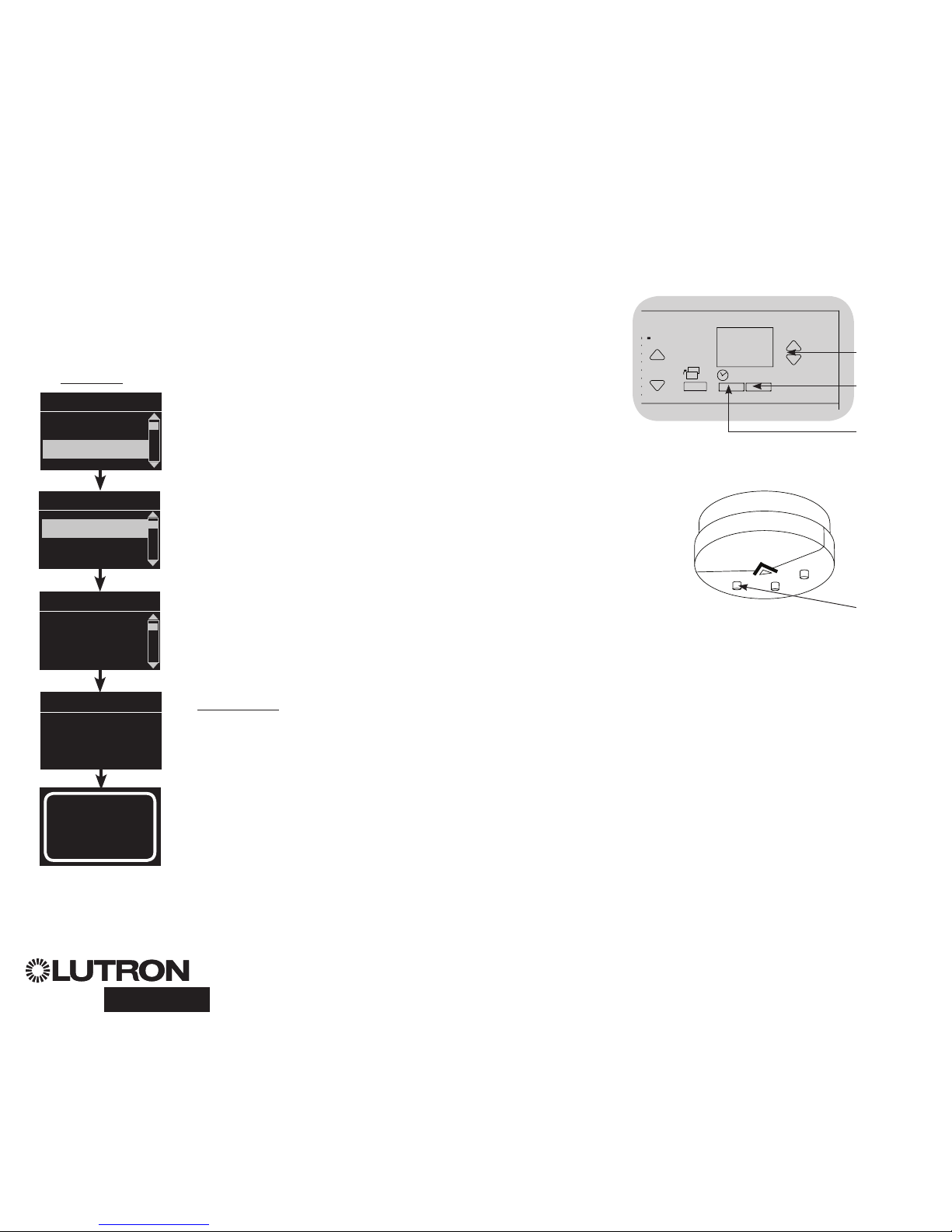
2. Enter programming mode (see page 9).
3. Use the Master buttons to highlight “Sensor setup” and press
the OK button to accept.
4. Use the Master buttons to highlight “Add wireless sensors” and
press the OK button to accept.
5. Press and hold the “Link” button on the front of the daylight
sensor until the sensor starts flashing. The info screen on the
GRAFIK Eye QS will display the sensor’s serial number.
6. Press the OK button on the GRAFIK Eye QS control unit. A
screen will confirm that the sensor has been assigned.
7. Repeat the above steps for all desired sensors.
8. Exit programming mode (see page 9).
To disassociate wireless daylight sensors and GRAFIK Eye QS
control units:
Refer to the Radio Powr Savr daylight sensor install guide to return
the sensor to its “out-of-box” functionality . Doing so will remove
its programming from the GRAFIK Eye QS control unit.
Note: The wireless signal has a range of 10 m (30 feet) through
standard construction.
Associating Wireless Daylight Sensors and GRAFIK Eye® QS Wireless Control Units
(for wireless enabled units only)
OK
16
9-16
1-8
Master
buttons
OK
button
Timeclock
(back) button
Main menu
Zone Setup
Sensor Setup
Daylight
SN: xxxx-xxxx:
press OK to Save
Add wireless sen
Initiate association
of sensors
Saved
*Assigned*
Sensor Setup
Daylight
Add wireless sensors
Link
button
®
GRAFIK Eye® QS with DALI Quick Installation and Operation Guide 17
For additional information, see the complete installation and operation guide at www.lutron.com/qs
Daylight Sensor Setup
Mode Assignment
This step allows you to assign daylight sensors on the QS link or connected to the
GRAFIK Eye® QS control unit. Sensors can be assigned in either Zone Mode or Group
Mode.
Zone Mode (default) is useful when the GRAFIK Eye QS is controlling lights in multiple
rooms or areas. Zone mode allows each zone to adjust its “outputted” light level based
on measured daylight levels. Only one sensor can be assigned to each zone (a sensor
can be assigned to more than one zone). Each zone can have a unique target light
level.
Group Mode is useful when groups or rows of lights for daylighting go across multiple
zones. A group can consist of any combination of DALI loads in the system. Each
group can be assigned to only one sensor (a sensor can be “shared by” more than one
group). Each group can have a unique target light level.
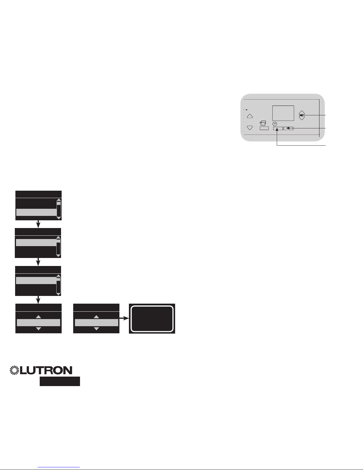
1. Enter programming mode (see page 9).
2. Use the Master buttons to highlight “Sensor setup” and press
the OK button to accept.
3. Use the Master buttons to highlight “Daylight” and press the
OK button to accept.
4. Use the Master buttons to highlight “Mode” and press the
OK button to accept.
5. Use the Master buttons to highlight “Zone Mode” to assign
sensors to zones, or “Group Mode” to assign sensors to a group
of DALI loads. Press the OK button to accept. A screen will
confirm your selected mode has been saved and you will return
to the Daylight Sensor screen.
To configure Zone Mode, see page 18. To configure Group
Mode, see page 19.
Note: Changing modes will remove all previous daylight
assignments.
OK
16
9-16
1-8
Master
buttons
OK
button
Timeclock
(back) button
Main menu
Zone Setup
Sensor Setup
Daylight Sensor
Zone Mode
Daylight Sensor
Setup
Mode
Saved
Saved
Daylight Sensor
Group Mode
OR
Sensor Setup
Occupancy
Daylight
®
GRAFIK Eye® QS with DALI Quick Installation and Operation Guide 18
For additional information, see the complete installation and operation guide at www.lutron.com/qs
Daylight Sensor Setup
Zone Mode
This step allows you to assign sensors to each zone, with one daylight sensor per
zone connected to the GRAFIK Eye® QS control unit. Sensors can be assigned to
more than one zone.
Select Sensors
1. If not already done, complete the steps on page 17, and
select “Zone Mode”.
2. Use the Master buttons to highlight “Setup” and press the
OK button to accept. Available sensors will be displayed.
3. You can assign one sensor per zone, and a sensor can be
assigned to more than one zone. Use the Master buttons to
scroll through the sensors until the one you wish to assign or
unassign is highlighted, and press the OK button to select it.
4. Use the zone raise and lower buttons for each zone to assign
or unassign the sensor to that zone. The zone raise button
assigns the displayed sensor, and the zone lower button
unassigns it. Repeat for all desired sensors and press OK. A
screen will verify your settings have been saved.
5. Calibrate sensors: Press the Timeclock (back) button to return
to the Daylight Sensor screen. Use the Master buttons to
select the desired group and press the OK button to accept.
6. Use the Master buttons to select the desired zone and press
the OK button to accept.
7. Put any wireless Radio Powr SavrTM daylight sensors
associated with the desired zones into Calibrate Mode: Press
and hold the “Cal” button for 6 seconds until the sensor
flashes.
8. Use the Master buttons to select the desired light level for the
zone, and press the OK button to accept. Repeat for all zone
levels you wish to calibrate. Press the OK button to accept.
9. Exit programming mode (see page 9).
Note: If wireless sensors are not found, verify that they are
associated correctly (see page 16).
Sensor x/y
Select
Zones
OK
1 2
3
4
5
6
9 10
11 12
13
14
7
815 16
9-16
1-8
OK
3
4
5
69 10
11 12
13
14
7
815 16
9-16
1-8
Zone raise
Zone lower
Daylight Sensor
Calibrate
Setup
Sensor x/y
SN: xxxx-xxxx:
Source: RF
Saved
Saved
3 seconds
Daylight Sensor
Setup
Calibrate
Saved
Searching
OK
16
9-16
1-8
Master
buttons
OK
button
Timeclock
(back) button
Sensor Name
Zone 1
Adjust Light
More light
Less light
Cal
button

®
GRAFIK Eye® QS with DALI Quick Installation and Operation Guide 19
For additional information, see the complete installation and operation guide at www.lutron.com/qs
Daylight Sensor Setup
Group Mode
This step allows you to assign daylight sensors to a group of DALI loads connected
to the GRAFIK Eye® QS control unit.
Set Up Groups
1. If not already done, complete the steps on page 17, and
select “Group Mode”.
2. Use the Master buttons to highlight “Daylight Groups” and
press the OK button to accept.
3. Use the Master buttons to scroll through the list of available
daylight groups. Up to 16 groups of DALI loads can be
defined. Press the OK button to accept.
4. Use the Master buttons to scroll through the DALI devices on
the link. Press the OK button to add or remove the selected
device. The currently selected device will display its current
assignment status:
Unassigned if it is not assigned to any group
Assigned if it is assigned to the selected (displayed) group
Group x if it is currently assigned to another group (x = the
group number it is assigned to)
5. Press the Timeclock (back) button to return to the list of
configurable groups, and repeat these steps to assign devices
to other groups.
Note: Each DALI device can be assigned to only one group.
Assigning a device already associated with another group will
replace its existing programming.
(continued on next page)
Daylight Sensor
Setup
Daylight Groups
Group 1
Ballast 2/23
*Unassigned*
OK
16
9-16
1-8
Master
buttons
OK
button
Timeclock
(back) button
Configure Groups
Group 1
Group 1
Ballast 2/23
*Assigned*
OR
Group 1
Ballast 2/23
*Group 2*
OR

®
GRAFIK Eye® QS with DALI Quick Installation and Operation Guide 20
For additional information, see the complete installation and operation guide at www.lutron.com/qs
Daylight Sensor Setup
Group Mode (continued)
Select Sensors
1. Press the Timeclock (back) button to return to the Daylight
Sensor menu.
2. Use the Master buttons to highlight “Setup” and press the
OK button to accept.
3. Use the Master buttons to scroll through the list of available
daylight sensors. When the desired sensor is displayed, press
the OK button to select it.
4. Use the Master buttons to scroll through the list of available
groups. When the desired group is displayed, press OK
to assign or unassign the sensor to that group. Press the
Timeclock (back) button to return to the list of available
sensors and repeat for additional sensors.
5. Calibrate sensors: Press the Timeclock (back) button to return
to the Daylight Sensor screen. Use the Master buttons to
select the desired group and press the OK button to accept.
6. Use the Master buttons to select the desired group and press
the OK button to accept.
7. Put any wireless Radio Powr SavrTM daylight sensors
associated with the desired groups into Calibrate Mode:
Press and hold the “Cal” button for 6 seconds until the sensor
flashes.
8. Use the Master buttons to select the desired light level for
the group, and press the OK button to accept. Repeat for all
group levels you wish to calibrate. Press the OK button to
accept.
9. Exit programming mode (see page 9).
Note: If wireless sensors are not found, verify that they are
associated correctly (see page 16).
Daylight Sensor
Calibrate
Setup
Sensor x/y
SN: xxxx-xxxx
Source: RF
OK
16
9-16
1-8
Master
buttons
OK
button
Timeclock
(back) button
Saved
Saved
3 seconds
Daylight Sensor
Setup
Calibrate
Calibrate
Group 1
Sensor x
Group 1
*Unassigned*
Sensor x
Group 1
*Assigned*
Adjust Light
More light
Less light
Cal
button
®
GRAFIK Eye® QS with DALI Quick Installation and Operation Guide 21
For additional information, see the complete installation and operation guide at www.lutron.com/qs
Scene Setup
Set Zone Levels, Fade Rates, and Window Treatment Group Actions
1. Enter programming mode (see page 9).
2. Use the Master buttons to highlight “Scene setup” and press
the OK button to accept.
3. Use the Master buttons to highlight “Levels” to adjust lighting
and/or window treatment levels. Press the OK button to
accept. Use the Master buttons to highlight the scene number
of your desired scene. Press the OK button to accept.
4. Set each zone to the desired light level for this scene using
the zone raise/lower buttons. The info screen will display the
zone and percentage as you adjust it.
To set a zone as unaffected, lower the light levels all the way
to off, then hold the zone lower button for 3 seconds. The
screen will display “---” and the three middle LEDs for the
zone will be lit to indicate this zone is unaffected by the scene
(the zone will not change when this scene is initiated).
When all zones are at the desired level, press the OK button to
accept.
5. Use the Master buttons to set the fade time for this scene.
Press the OK button to accept.
6. Note: This step is applicable only if you have window
treatments on your system. If you do not have or do not wish
to set window treatment groups for this scene, press the OK
button to skip this step.
Press the shade button that will take the window treatments
assigned to that button group to the level you want for this
scene. Repeat for any additional shade button groups. Press
the OK button to accept. For window treatment programming,
see the complete installation and operation guide at www.
lutron.com/qs.
7. The info screen will confirm that your scene has been saved.
8. Exit programming mode (see page 9).
Main menu
Timeclock
Scene setup
Scene setup
Labels
Levels
Scene 1
Adjust fade
seconds
Scene 1
Set shade
Groups
3 seconds
Scene 1
Set zones
Scene setup
Scene 1
Saved
3
Shade
button group
OK
1 2
3
4
5
6
9 10
11 12
13
14
7
815 16
9-16
1-8
OK
3
4
5
69 10
11 12
13
14
7
815 16
9-16
1-8
Zone raise
Zone lower
OK
16
9-16
1-8
Master
buttons
OK
button
Timeclock
(back) button

Symptom Possible Causes Remedy
Unit does not control loads
Unit does not turn lights on
LEDs on front of unit are not ON
Circuit breaker is tripping
Circuit breaker is off
Low zone settings
Miswire
System short circuit
System overload
Switch circuit breaker on
Reprogram scenes to a higher intensity
Check wiring
Find and correct shorts
Make sure unit is not overloaded (see Zone Setup section))
Unit does not control load
Zone control does not work
Miswire
Disconnected wire
Burned-out lamps
Check wiring
Connect zone wires to loads
Replace bad lamps
1 or more zones are “full on” when any scene is
on and zone intensity is not adjustable
Miswire
Shorted line output
Make sure loads are connected to the right zones
Replace control unit
A Zone control affects more than one zone Miswire Check for shorts between zone outputs
Keypad buttons are not working
Keypad LEDs are not tracking
Miswire or loose connection on QS link
Wallstation programming is incorrect
Tighten loose connections at PELV terminals on all units and
other devices in the system
Check the keypad function and programming on the units
Faceplate is warm Normal operation Solid-state controls dissipate about 2% of the connected load
as heat.
Unit does not allow scene change or zone
adjustments
Cannot program fade time from Off
Unit in wrong save mode
Keypad in system has locked the unit
Fade time from Off not programmable;
can only program fade time to Off
Change to correct save mode
Check programming and state of keypads
Fade time from Off is always 3 seconds
Integral (direct-wired) contact closure input does
not work
Miswire
Input closure/opening is not occurring
Unit is in wrong CCI mode
Check wiring on contact closure input
Check that the input device is opening and closing properly
Change to correct CCI mode
Timeclock events do not occur
Sunrise or sunset events do not occur at the
correct time
Timeclock is disabled
Time is not set correctly
Date is not set correctly
Location is not set correctly
Holiday schedule is in effect
Enable the timeclock
Set the time
Set the date
Set the latitude and longitude correctly
Remove the holiday schedule from your programming
Troubleshooting
®
GRAFIK Eye® QS with DALI Quick Installation and Operation Guide 22
For additional information, see the complete installation and operation guide at www.lutron.com/qs
®
GRAFIK Eye® QS with DALI Quick Installation and Operation Guide 23
For additional information, see the complete installation and operation guide at www.lutron.com/qs
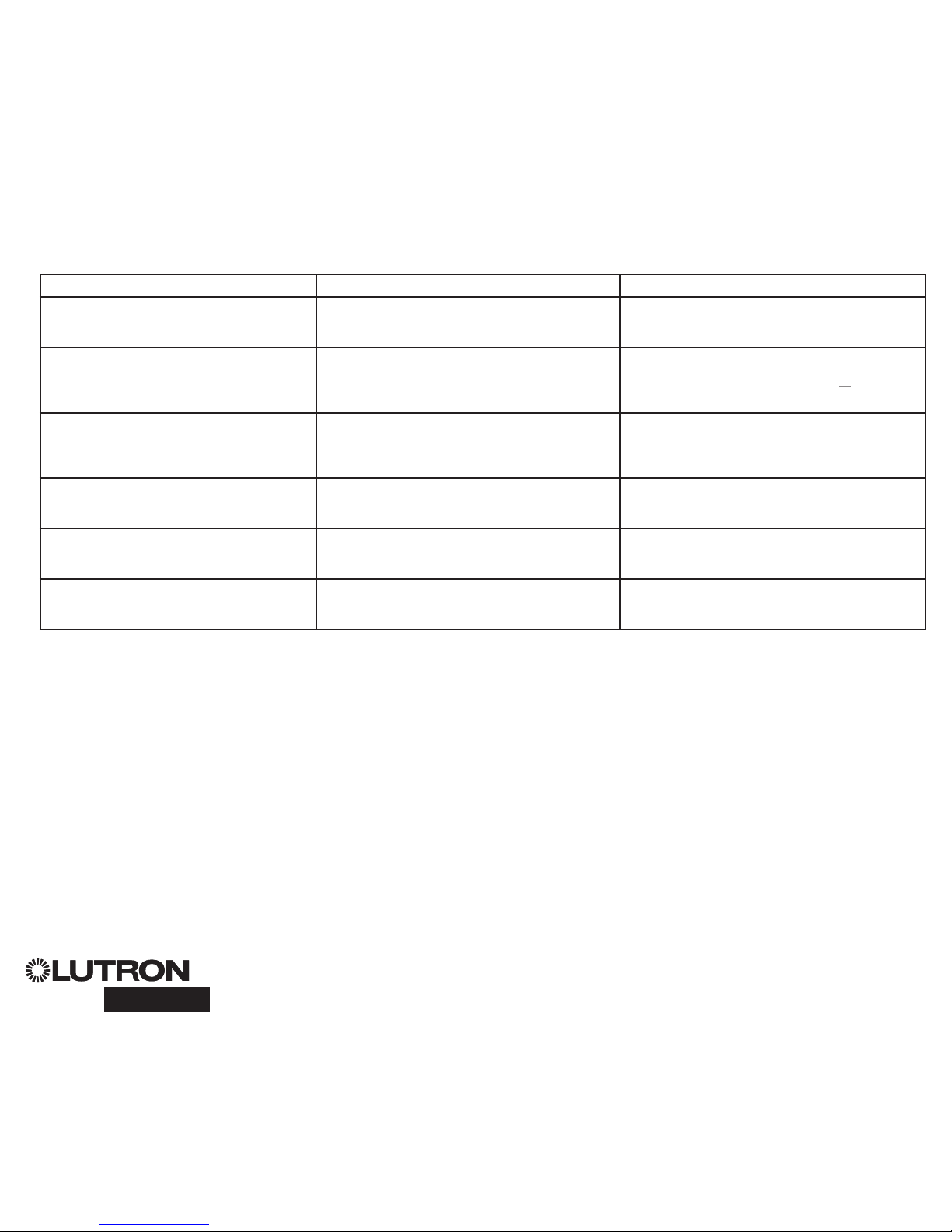
Troubleshooting (continued): DALI Functions
Symptom Possible Causes Remedy
Cannot add a DALI device to a zone
after a “Build System” or “Address all” command
has been run
Zone is not set to DALI Set the zone to DALI
DALI device at full brightness cannot be controlled D1 and D2 are not connected Check D1 and D2 connections on the back of the
GRAFIK Eye QS with DALI
Check voltage: Minimum voltage of 12 V
DALI devices do not flash when running the “Build
System” command
DALI devices are not addressed
DALI devices are miswired
Address DALI devices
Check D1 and D2 wiring, and power wiring to DALI
devices
DALI device is not affected by a level change DALI device is not assigned to a zone Run the “Address all” command and assign the DALI
device to a zone
DALI device light levels can be lowered, but not
raised to full On
DALI device is being affected by the daylight sensors Recalibrate the associated daylight sensors
“Build System” command does not find DALI loads D1 and/or D2 are miswired or not connected Check wiring; if wiring is correct, call Lutron Technical
Support

®
Lutron Electronics Co., Inc.
One Year Limited Warranty
For a period of one year from the date of purchase, and subject
to the exclusions and restrictions described below, Lutron warrants
each new unit to be free from manufacturing defects. Lutron will,
at its option, either repair the defective unit or issue a credit equal
to the purchase price of the defective unit to the Customer against
the purchase price of comparable replacement part purchased
from Lutron. Replacements for the unit provided by Lutron or, at its
sole discretion, an approved vendor may be new, used, repaired,
reconditioned, and/or made by a different manufacturer.
If the unit is commissioned by Lutron or a Lutron approved third
party as part of a Lutron commissioned lighting control system, the
term of this warranty will be extended, and any credits against the
cost of replacement parts will be prorated, in accordance with the
warranty issued with the commissioned system, except that the
term of the unit’s warranty term will be measured from the date of
its commissioning.
EXCLUSIONS AND RESTRICTIONS
This Warranty does not cover, and Lutron and its suppliers are not
responsible for:
1. Damage, malfunction or inoperability diagnosed by Lutron or
a Lutron approved third party as caused by normal wear and
tear, abuse, misuse, incorrect installation, neglect, accident,
interference or environmental factors, such as (a) use of
incorrect line voltages, fuses or circuit breakers; (b) failure to
install, maintain and operate the unit pursuant to the operating
instructions provided by Lutron and the applicable provisions
of the National Electrical Code and of the Safety Standards
of Underwriter’s Laboratories; (c) use of incompatible devices
or accessories; (d) improper or insufficient ventilation; (e)
unauthorised repairs or adjustments; (f) vandalism; or (g) an act
of God, such as fire, lightning, flooding, tornado, earthquake,
hurricane or other problems beyond Lutron’s control.
2. On-site labor costs to diagnose issues with, and to remove,
repair, replace, adjust, reinstall and/or reprogram the unit or any
of its components.
3. Equipment and parts external to the unit, including those sold
or supplied by Lutron (which may be covered by a separate
warranty).
4. The cost of repairing or replacing other property that is damaged
when the unit does not work properly, even if the damage was
caused by the unit.
EXCEPT AS EXPRESSLY PROVIDED IN THIS WARRANTY,
THERE ARE NO EXPRESS OR IMPLIED WARRANTIES OF ANY
TYPE, INCLUDING ANY IMPLIED WARRANTIES OF FITNESS FOR
A PARTICULAR PURPOSE OR MERCHANTABILITY. LUTRON
DOES NOT WARRANT THAT THE UNIT WILL OPERATE WITHOUT
INTERRUPTION OR BE ERROR FREE.
NO LUTRON AGENT, EMPLOYEE OR REPRESENTATIVE HAS
ANY AUTHORITY TO BIND LUTRON TO ANY AFFIRMATION,
REPRESENTATION OR WARRANTY CONCERNING THE UNIT.
UNLESS AN AFFIRMATION, REPRESENTATION OR WARRANTY
MADE BY AN AGENT, EMPLOYEE OR REPRESENTATIVE IS
SPECIFICALLY INCLUDED HEREIN, OR IN STANDARD PRINTED
MATERIALS PROVIDED BY LUTRON, IT DOES NOT FORM A
PART OF THE BASIS OF ANY BARGAIN BETWEEN LUTRON AND
CUSTOMER AND WILL NOT IN ANY WAY BE ENFORCEABLE BY
CUSTOMER.
IN NO EVENT WILL LUTRON OR ANY OTHER PARTY BE LIABLE
FOR EXEMPLARY, CONSEQUENTIAL, INCIDENTAL OR SPECIAL
DAMAGES (INCLUDING, BUT NOT LIMITED TO, DAMAGES FOR
LOSS OF PROFITS, CONFIDENTIAL OR OTHER INFORMATION, OR
PRIVACY; BUSINESS INTERRUPTION; PERSONAL INJURY; FAILURE
TO MEET ANY DUTY, INCLUDING OF GOOD FAITH OR OF
REASONABLE CARE; NEGLIGENCE, OR ANY OTHER PECUNIARY
OR OTHER LOSS WHATSOEVER), NOR FOR ANY REPAIR WORK
UNDERTAKEN WITHOUT LUTRON’S WRITTEN CONSENT ARISING
OUT OF OR IN ANY WAY RELATED TO THE INSTALLATION,
DEINSTALLATION, USE OF OR INABILITY TO USE THE UNIT OR
OTHERWISE UNDER OR IN CONNECTION WITH ANY PROVISION
OF THIS WARRANTY, OR ANY AGREEMENT INCORPORATING
THIS WARRANTY, EVEN IN THE EVENT OF THE FAULT, TORT
(INCLUDING NEGLIGENCE), STRICT LIABILITY, BREACH OF
CONTRACT OR BREACH OF WARRANTY OF LUTRON OR ANY
SUPPLIER, AND EVEN IF LUTRON OR ANY OTHER PARTY WAS
ADVISED OF THE POSSIBILITY OF SUCH DAMAGES.
NOTWITHSTANDING ANY DAMAGES THAT CUSTOMER
MIGHT INCUR FOR ANY REASON WHATSOEVER (INCLUDING,
WITHOUT LIMITATION, ALL DIRECT DAMAGES AND ALL
DAMAGES LISTED ABOVE), THE ENTIRE LIABILITY OF LUTRON
AND OF ALL OTHER PARTIES UNDER THIS WARRANTY ON ANY
CLAIM FOR DAMAGES ARISING OUT OF OR IN CONNECTION
WITH THE MANUFACTURE, SALE, INSTALLATION, DELIVERY,
USE, REPAIR, OR REPLACEMENT OF THE UNIT, OR ANY
AGREEMENT INCORPORATING THIS WARRANTY, AND
CUSTOMER’S SOLE REMEDY FOR THE FOREGOING, WILL BE
LIMITED TO THE AMOUNT PAID TO LUTRON BY CUSTOMER
FOR THE UNIT. THE FOREGOING LIMITATIONS, EXCLUSIONS
AND DISCLAIMERS WILL APPLY TO THE MAXIMUM EXTENT
ALLOWED BY APPLICABLE LAW, EVEN IF ANY REMEDY FAILS
ITS ESSENTIAL PURPOSE.
TO MAKE A WARRANTY CLAIM
To make a warranty claim, promptly notify Lutron within the
warranty period described above by calling the Lutron Technical
Support Center at (800) 523-9466. Lutron, in its sole discretion, will
determine what action, if any, is required under this warranty. To
better enable Lutron to address a warranty claim, have the unit’s serial
and model numbers available when making the call. If Lutron, in its
sole discretion, determines that an on-site visit or other remedial action
is necessary, Lutron may send a Lutron Services Co. representative
or coordinate the dispatch of a representative from a Lutron approved
vendor to Customer’s site, and/or coordinate a warranty service call
between Customer and a Lutron approved vendor.
This warranty gives you specific legal rights, and you may also
have other rights which vary from state to state. Some states do
not allow limitations on how long an implied warranty lasts, so the
above limitation may not apply to you. Some states do not allow
the exclusion or limitation of incidental or consequential damages,
so the above limitation or exclusion may not apply to you.
These products may be covered under one or more of
the following U.S. patents: 5,191,265; 5,430,356; 5,463,286;
5,838,226; 5,848,054; 5,905,442; 5,949,200; 5,982,103;
6,091,205; 6,188,181; 6,380,692; 6,687,487; 6,803,728;
D546,294; D547,733; D547,734; D550,163; D550,164;
D550,165; D550,166; D551,179; D552,042; and corresponding
foreign patents. Other U.S. and foreign patents may be pending.
NEC is a registered trademark of the National Fire Protection
Association, Quincy, Massachusetts.
Lutron, the sunburst logo, Sivoia, seeTouch, and GRAFIK Eye are
registered trademarks and Radio Powr Savr is a trademark of Lutron
Electron ics Co., Inc.
© 2010 Lutron Electronics Co., Inc.
Internet: www.lutron.com
E-mail: product@lutron.com
WORLD HEADQUARTERS
USA
Lutron Electronics Co., Inc.
7200 Suter Road, Coopersburg, PA 18036-1299
TEL +1.610.282.3800
FAX +1.610.282.1243
Toll-Free 1.888.LUTRON1
Technical Support 1.800.523.9466
North and South America Technical Hotlines
USA, Canada, Caribbean: 1.800.523.9466
Mexico: +1.888.235.2910
Central/South America: +1.610.282.6701
EUROPEAN HEADQUARTERS
United Kingdom
Lutron EA Ltd.
6 Sovereign Close, London, E1W 3JF United Kingdom
TEL +44.(0)20.7702.0657
FAX +44.(0)20.7480.6899
FREEPHONE (UK) 0800.282.107
Technical support +44.(0)20.7680.4481
ASIAN HEADQUARTERS
Singapore
Lutron GL Ltd.
15 Hoe Chiang Road, #07-03 Euro Asia Centre,
Singapore 089316
TEL +65.6220.4666
FAX +65.6220.4333
Asia Technical Hotlines
Northern China: 10.800.712.1536
Southern China: 10.800.120.1536
Hong Kong: 800.901.849
Indonesia: 001.803.011.3994
Japan: +81.3.5575.8411
Macau: 0800.401
Singapore: 800.120.4491
Taiwan: 00.801.137.737
Thailand: 001.800.120.665853
Other countries: +65.6220.4666
Warranty
Lutron Electronics Co., Inc.
Made and printed in U.S.A.
P/N 032-310 Rev. A 03.18.10
Contact Information
LUTRON
con DALI
Guía Rápida de
Instalación y
Funcionamiento
®
Por favor lea
Atenuador de luz
La unidad de control GRAFIK Eye QS con DALI permite
controlar tanto luces como cortinas, sin necesidad de interfaces,
utilizando una única unidad de control. Incluye un botón a
presión para recordar escenas, una pantalla de información que
despliega el estado y los ahorros de energía, un receptor IR, un
reloj astronómico, una entrada de cierre de contacto, y botones
de luz posterior grabables que son fáciles de encontrar y operar.
El enlace de bus incorporado DALI puede controlar hasta 64
dispositivos DALI.
Números de Modelo: QSGRK-6D, QSGRK-8D, QSGRK-16D
QSGR-6D, QSGR-8D, QSGR-16D
Valores nominales: 100 - 240 V 50/60 Hz 100 mA
CE 230 V 50/60 Hz 100 mA
Salida: Cableado PELV (Clase 2: E.U.A.) 24 V 150 mA
Enlace DALI: 18 V 250 mA
Contenido
Características y Funciones ...................................... 2
Cableado del GRAFIK Eye® QS con DALI
Descripción General del Cableado de la Línea
de Voltaje/Alimentación y del DALI ..................... 3
Detalles del cableado de voltaje de línea ..............4
Detalles de cableado del Bus DALI ...................... 5
Descripción general del Cableado PELV
(Clase 2: E.U.A.) ....................................................6
Detalles del Cableado de control del enlace QS .. 7
Finalización de la instalación ............................ 8
Modo de Programación .........................................9
Modo inalámbrico ............................................10
Configuración de Zona ......................................... 11
Generalidades de configuración del DALI
Construcción del Sistema ..................................... 12
Configuración del DALI ........................................13
Cómo Asociar los Sensores de Ocupación
Inalámbricos ...................................................14
Configuración del sensor de ocupación
Modo Escena......................................................... 15
Cómo asociar los Sensores inalámbricos
de luz del dia ..................................................16
Configuración del sensor de luz del dia
Modo Asignación ..................................................17
Modo Zona ............................................................18
Modo Grupo ..........................................................19
Configuración de Escena .................................... 21
Solución de Problemas ....................................22
Solución de problemas:
Funciones de DALI ........................................23
Garantía, Información de contacto .................24
Para información adicional, consulte la guía
completa de instalación y operación en
www.lutron.com/qs
Español
OK
1 2
3
4
5
69 10
11 12
13
14
7
815 16
9-16
1-8
Pantalla de Información
Mostrar estado o funciones
de programación
Botones de escena
Con indicadores LED
de escenas integrales
Grupos opcionales
de botones de cortina
(tratamientos de ventanas)
Botones predeterminados
y aumentar/disminuir
con LEDs integrales (máximo
de 3 grupos de botones)
Números de zonas
Botones de aumentar y
disminuir la intensidad
de la zona
Los Indicadores LED de zona
muestran los niveles actuales
de iluminación de las zonas
Botón de reloj
Despliega la información actual
del reloj
Botón de OK
Usado para programar
el tiempo de desvanecimiento
Receptor infrarrojo
Para uso remoto de mano
Botones Maestros
Aumente y disminuya
temporalmente los niveles
de iluminación en la unidad
USB tipo mini B
Para la programación mediante PC
{
Placa frontal con bisagras
Placa frontal con bisagras
Características y Funciones del Sistema GRAFIK Eye® QS con DALI
Botón de página
Cambia entre el despliegue
de las zonas 1 a 8 y 9 a 16
en la unidad de 16 zonas
Nota: la unidad de control de 6 zonas mostrará solamente las zonas 1 a 6.
®
Para información adicional, consulte la guía completa de instalación y operación en www.lutron.com/qs
Guía Rápida de Instalación y Operación del GRAFIK Eye® QS con DALI 2
®
Para información adicional, consulte la guía completa de instalación y operación en www.lutron.com/qs
Guía Rápida de Instalación y Operación del GRAFIK Eye® QS con DALI 3
Cableado del GRAFIK Eye® QS con DALI:
Visión del cableado del voltaje de línea y del DALI
4,0 mm2 (12 AWG) cada
terminal
Cables de la Línea
de Voltaje/Alimentación
y Cableado de Carga
D2
D1
D2
D1
A dispositivos
adicionales DALI
Cableado del Bus DALI
(Consulte la página 5 para obtener la
especificación completa del cableado)
Dos 1,5 mm2 (16 AWG) cada terminal
Dispositivos DALI:
balastos, drivers, o interfaces
Para facilitar el cableado y para proveer
dos puntos de conexión, se proveen dos
conexiones D1 y dos D2; hay solamente
un enlace DALI en la unidad.
Nota: Los balastos y demás dispositivos DALI
NO deben ser alimentados desde una salida
de voltaje de línea en el GRAFIK Eye QS con
DALI.
Panel de
Distribución
L
N
L
N
Etiquetas de los terminales:
L: Vivo
N: Neutro
: Tierra
Panel de
distribución
de 100 - 240 V
50 / 60 Hz

Cableado del GRAFIK Eye® QS con DALI:
Detalles del cableado de voltaje de línea
•
Utilice cable que esté apropiadamente certificado
para todos los cables de las líneas de voltaje/
alimentación.
• Se debe brindar protección apropiada contra
cortocircuitos y sobrecargas en el panel de
distribución.
• Realice la instalación de acuerdo con todos los
códigos eléctricos locales y nacionales.
• PELV (Clase 2: E.U.A.) los terminales deben
ser
desenchufados temporalmente para facilitar
el
cableado del sensor de ocupación, del IR, y de
control.
•
Aviso: Riesgo de daños a la unidad. No
conecte
cable de línea de voltaje/alimentación
a los terminales PELV (Clase 2: E.U.A.).
Paso 1: Instale la caja de empotrar. Monte
una caja de empotrar U.S. de 4 dispositivos
a 89 mm (3,5 pulg) de profundidad en una
superficie interior seca y llana que sea accesible
y permita la programación y el funcionamiento
del sistema. Deje al menos 110 mm (4,5 pulg)
libres por encima y por debajo de la placa frontal
para asegurar una correcta disipación del calor.
Deje 25 mm (1 pulg) que sobresalga a ambos
lados de la placa frontal.
Nota: caja de empotrar de 4 dispositivos
disponible en Lutron; P/N 241400.
Paso 2: Verifique el cableado de la unidad
de control.
•
La conexión del terminal de tierra/masa debe
realizarse como se muestra en los diagramas
de cableado (consulte la página 3).
•
No mezcle distintos tipos de carga en la
misma zona.
•
Ajústese a todos los códigos locales y nacionales
al instalar el cableado PELV (Clase 2: E.U.A.)
con
cableado de línea de voltaje/alimentación.
¡ADVERTENCIA! Peligro de
electrocución. Puede causar
lesiones graves o la muerte. Apague
siempre el cortacircuito o quite el
fusible del circuito de alimentación
antes de realizar cualquier trabajo.
Antes de conectar las cargas a la
unidad de control GRAFIK Eye QS
con DALI, compruebe si las cargas
presentan cortocircuitos.
Paso 3: Conecte el voltaje de línea
y las cargas en la unidad de control.
•
Pele 8 mm (5/16 pulg) de aislación de los cables
de línea de voltaje/alimentación en la caja
de empotrar.
• Conecte los cables de voltaje de línea/
alimentación, tierra y carga a los terminales
correspondientes en la parte posterior
de la unidad de control.
L: Vivo
N: Neutro
:Tierra
El torque recomendado para la instalación es
de 0,6 N∙m (5,0 pulg∙lbs) para las conexiones
de alimentación/voltaje de línea y 0,6 N∙m
(5,0 pulg∙lbs) para la conexión a tierra/masa.
Aviso: Riesgo de daño a la unidad. Las
unidades de control GRAFIK Eye QS con
DALI deben ser instaladas por un electricista
calificado conforme a todas las regulaciones
aplicables y códigos de construcción.
Un cableado incorrecto puede dañar las
unidades de control u otros equipos.
Nota: Para evitar el sobrecalentamiento
y posibles daños a los equipos, no
instale unidades de control para atenuar
receptáculos, aparatos a motor, o
iluminación fluorescente no equipada con
DALI balastos de atenuación electrónica,
u otros dispositivos DALI aprobados para
su ubicación.
Las unidades de control están
diseñadas para el uso residencial
y comercial,
solamente para uso en interiores.
LUTRON
LUTRON
La placa frontal sobresale
de la caja de empotrar
en ambos lados; deje
25 mm (1 pulg)
110 mm
(4,5 pulg)
8 mm
(5/16 pulg)
®
Para información adicional, consulte la guía completa de instalación y operación en www.lutron.com/qs
Guía Rápida de Instalación y Operación del GRAFIK Eye® QS con DALI 4
®
Para información adicional, consulte la guía completa de instalación y operación en www.lutron.com/qs
Guía Rápida de Instalación y Operación del GRAFIK Eye® QS con DALI 5
El cableado del Bus DALI puede ser
considerado NEC® Clase 1 o PELV (Clase 2:
E.U.A.).
• NEC® Clase 1: El cableado del bus DALI
puede tenderse en el mismo conducto que el
cableado de voltaje de línea a los artefactos.
• PELV (Clase 2: E.U.A.): El cableado de bajo
voltaje del bus DALI debe separarse de todos
los cableados de alimentación y NEC
® Clase
1.
• Consulte los códigos nacionales y locales
aplicables para verificar su cumplimiento.
• Lutron recomienda usar dos colores diferentes
para los cables D1 y D2 (bus DALI). Esto
evitará errores de cableado en cajas de empalmes
donde se combinan cables de bus DALI
de varios colores. Use las instrucciones
siguientes para el cableado del bus
DALI.
•
Cada enlace
DALI
puede tener solamente 1
GRAFIK Eye QS con DALI conectado. No
puede haber ningún bus de alimentación DALI
adicional en el enlace.
• Pueden conectarse hasta 64 dispositivos DALI
adicionales al enlace DALI
• No pueden conectarse otros dispositivos al
enlace DALI.
¡ADVERTENCIA! Peligro de
choque eléctrica. Puede resultar
en lesiones graves o la muerte.
No cablee en vivo. Interrumpa la
alimentación mediante el disyuntor
antes de cablear y dar servicio al bus
de alimentación DALI.
Paso 1: Use el siguiente cuadro de tamaños
de cable para determinar cuál usar dependiendo
del largo del Bus DALI.
Paso 2: Cablee el bus DALI desde terminal D1
y terminal D2 a todos los dispositivos DALI.
Paso 3: Separe el cableado del DALI del de
alimentación de línea. Si cablea el bus DALI
como PELV (Clase 2: E.U.A.), mantenga una
separación adecuada entre los cableados de
línea y los cableados NEC® Clase 1.
Paso 4: Conecte el disyuntor para energizar.
Bus DALI
18 V
250 mA
Cableado del GRAFIK Eye® QS con DALI:
Detalles del cableado del bus
DALI
Tamaño del Cableado y Largo del Bus
Los cables D1 y D2 del bus DALI no son
sensibles a la polaridad. El largo del Bus DALI
está limitado por el calibre del cable usado
para D1 y D2 de la siguiente forma:
Calibre
del Cable
Largo máximo
del bus DALI
4,0 mm
2
(12 AWG)
671 m (2 200 pies)
2,5 mm
2
(14 AWG)
1 400 m (427 pies)
1,5 mm
2
(16 AWG)
275 m (900 pies)
1,0 mm
2
(18 AWG)
570 m (175 pies)
Los cables del bus DALI 1,5 mm
2
(16 AWG)
están disponibles en Lutron, con los números
de parte C-CBL-216-GR-1 (non-plenum) y
C-PCBL-216-CL-1 (plenum).
Cableado de la Entrada
de Cierre de Contacto
Para las configuraciones, avanzadas en el
manual completo de instalación y operación, en
www.lutron.com/qs.
1 2
A B C
N H 1 2 3 4 5 6
1 2 3 4
1 2
1 2
A B C
Nota: Utilice dispositivos de conexión de cables
apropiados según los códigos locales.
Ejemplo: Sensores
de ocupación
(máximo 1)
1: COM
2: 24 V *
3: MUX
4: MUX
Controle el Cableado
Cableado del Sistema GRAFIK Eye® QS con DALI:
Visión general del cableado PELV (Clase 2: E.U.A.)
Cableado del IR
Desde conexión
externa del IR
(de terceros)
1,0 mm
2
(18 AWG)
cada terminal
1,0 mm
2
(18 AWG) cada
terminal
1: IR DATA
2: IR COM
A: CCI SIG
B: 24 V
C: CCI COM
A estaciones de control,
cortinas u otras unidades de
control GRAFIK Eye QS
Datos (terminal 3 y 4):
Un par trenzado, blindado 0,5 mm2 (22 AWG)
para cada terminal
Común y de alimentación (terminales 1 y 2):
Dos 1,0 mm2 (18 AWG) cada terminal
* No conecte el terminal 2 entre un
GRAFIK Eye QS y cualquier otra
fuente de alimentación, incluida
otra unidad GRAFIK Eye QS.
Avanzadas en el manual completo
de instalación y operación, en
www.lutron.com/qs, para un
ejemplo del detalle del cableado.
®
Para información adicional, consulte la guía completa de instalación y operación en www.lutron.com/qs
Guía Rápida de Instalación y Operación del GRAFIK Eye® QS con DALI 6
 Loading...