

Lutron Electronics QSGRJ-3P, QSGR-4P, QSGRJ-6P, QSGR-3P, QSGR-6P Installation And Operation Manual
...Page 1

LUTRON
Control Unit
Installation and Operation Guide
®
Please Read
The GRAFIK Eye® QS control unit allows for
control of both lights and shades, without
interfaces, using a single control unit.
Features include pushbutton scene recall,
info screen that displays energy savings and
status, IR receiver, astronomic timeclock,
contact closure input, and engravable
backlit buttons that are easy to find and
operate.
Model Numbers: QSGRJ-3P, QSGRJ-4P, QSGRJ-6P
QSGR-3P, QSGR-4P, QSGR-6P
120 V~ 50/60 Hz 220 - 240 V~ 50/60 Hz
Unit Capacity (watts) 2000 W 3000 W
MLV 2000 VA / 1600 W 3000 VA / 2400 W
Zone Capacity (watts) 25 – 800 W 40 – 1200 W
MLV 25 – 800 VA / 25 – 600 W 40 – 1200 VA / 40 – 960 W
See page 7 for IEC PELV/NEC® Class 2 ratings.
For California residents only:
The batteries in these devices contain
Perchlorate Material – special handling may apply.
For more information visit
www.dtsc.ca.gov/hazardouswaste/perchlorate
English
Español
Français
Page 2
®
GRAFIK Eye® QS Control Unit Installation and Operation Guide 2
Contents
Features and Functions of the
GRAFIK Eye® QS Control Unit .................3
Wiring the GRAFIK Eye® QS Control Unit
Overview of Line Voltage/Mains Wiring .........4
Line Voltage Wiring Details...................5
Overview of IEC PELV/NEC® Class 2 Wiring .....7
QS Link Control Wiring Details................8
Powering More Than 3 Wallstations Example....9
Completing Installation of the
GRAFIK Eye® QS Control Unit ............10
General Functionality ...................11
Pre-Programmed Button Functionality .....12
Zone Button Operation
Zone LED Displays for % of Lighting Levels....13
Programming Mode
Entering and Exiting Programming Mode ......14
Navigating Menus in Programming Mode ......14
Wireless Mode......................... 15
FCC Information ..........................15
Zone Setup
Assigning Load Types......................16
Assigning Non-Dim Load Types..............16
Setting Load Types ........................17
Setting High End or Low End Trim............18
Setting Minimum Level (optional).............18
Labeling a Zone (optional) ..................19
Scene Setup
Setting Zone Levels, Fade Rates,
and Shade Group Actions ..................20
Labeling a Scene (optional) .................21
Enabling/Disabling Daylighting in a Scene .....21
Setting Save Mode
Save Mode Settings .......................22
Quick Scene Programming:
Save by OK Mode .........................22
Contact Closure Input (CCI) Setup.........23
Occupancy Sensor Setup................25
Associating Wireless Occupancy Sensors .....26
Selecting the Mode ........................27
Scene Mode .............................28
Zone Mode ..............................29
Labeling an Occupancy Sensor (optional)......30
Configuring Occupancy Sensor Settings
(optional) ................................31
Daylight Sensor Setup ..................32
Associating Wireless Daylight Sensors ........33
Assigning Sensors.........................34
Calibrating Sensors........................34
Labeling a Daylight Sensor (optional) .........35
Pico® Wireless Control Setup .............36
Associating with a GRAFIK Eye® QS
Wireless Control Unit ......................37
Associating through a QS Sensor Module .....38
IR Setup ..............................39
Enabling/Disabling the IR Receiver ...........40
Associating the QS IR Eye with a
GRAFIK Eye® QS Control Unit ...............41
Associating through a QS Sensor Module .....43
Associating Sivoia® QS Shades/Drapes
and GRAFIK Eye® QS Control Units........44
Adjusting Shade Settings
Setting Limits.............................45
Preset Adjustment: Simple Method ...........46
Preset Adjustment: Advanced Method ........46
Naming a Group of Shades .................47
Enable/Disable “Stop If Moving” Functionality . . 48
Associating Sivoia® QS Triathlon® Shades with
GRAFIK Eye® QS Control Unit . . . . . . . . . 49
Setting Upper and Lower Limits of a
Sivoia® QS Triathlon® Shade with
GRAFIK Eye® QS Control Unit . . . . . . . . . 50
Associating Multiple GRAFIK Eye® QS
Control Units ..........................51
Timeclock Operation
Setting Time and Date .....................52
Setting Location ..........................53
Setting Daylight Saving Time ................53
Adding an Event ..........................54
Deleting an Event .........................55
Viewing an Event..........................55
Setting a Holiday ..........................56
Viewing a Holiday .........................56
Deleting a Holiday .........................56
Copying a Schedule .......................57
Deleting a Schedule .......................57
Afterhours ............................58
Afterhours Examples.......................59
Setting Up Afterhours ......................60
Ending Afterhours .........................60
Diagnostics and Special Settings
Enabling/Disabling the Timeclock ............61
Enabling/Disabling the Backlighting ..........61
Diagnostics ..............................61
Setting the Security Password ...............62
Language Selection ....................63
Faceplate Removal . . . . . . . . . . . . . . . . . . . . . 63
Troubleshooting .......................64
Troubleshooting: Wireless Functions.......65
Troubleshooting: Shade Functions ........66
Warranty .............................67
Contact Information ....................67
Page 3
OK
®
GRAFIK Eye® QS Control Unit Installation and Operation Guide 3
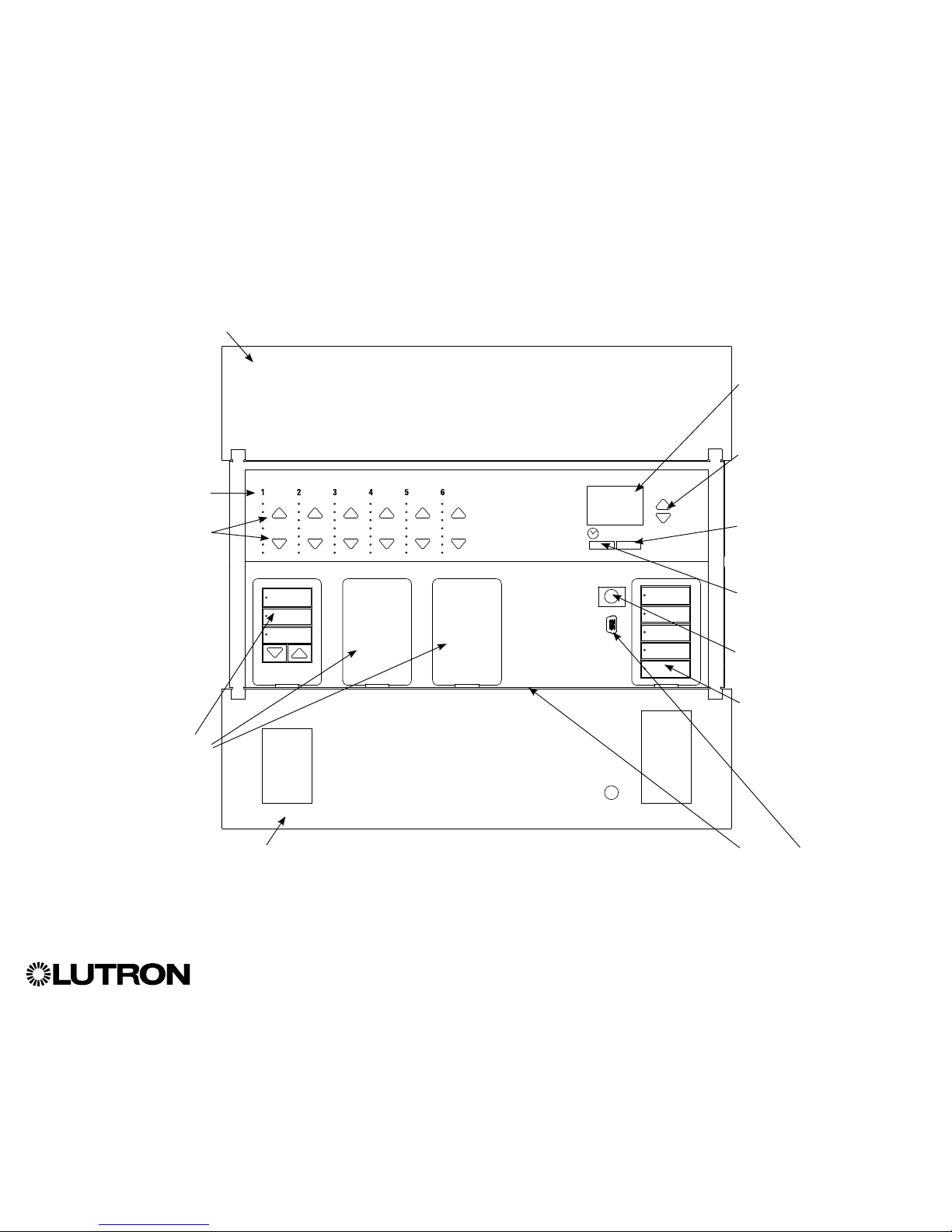
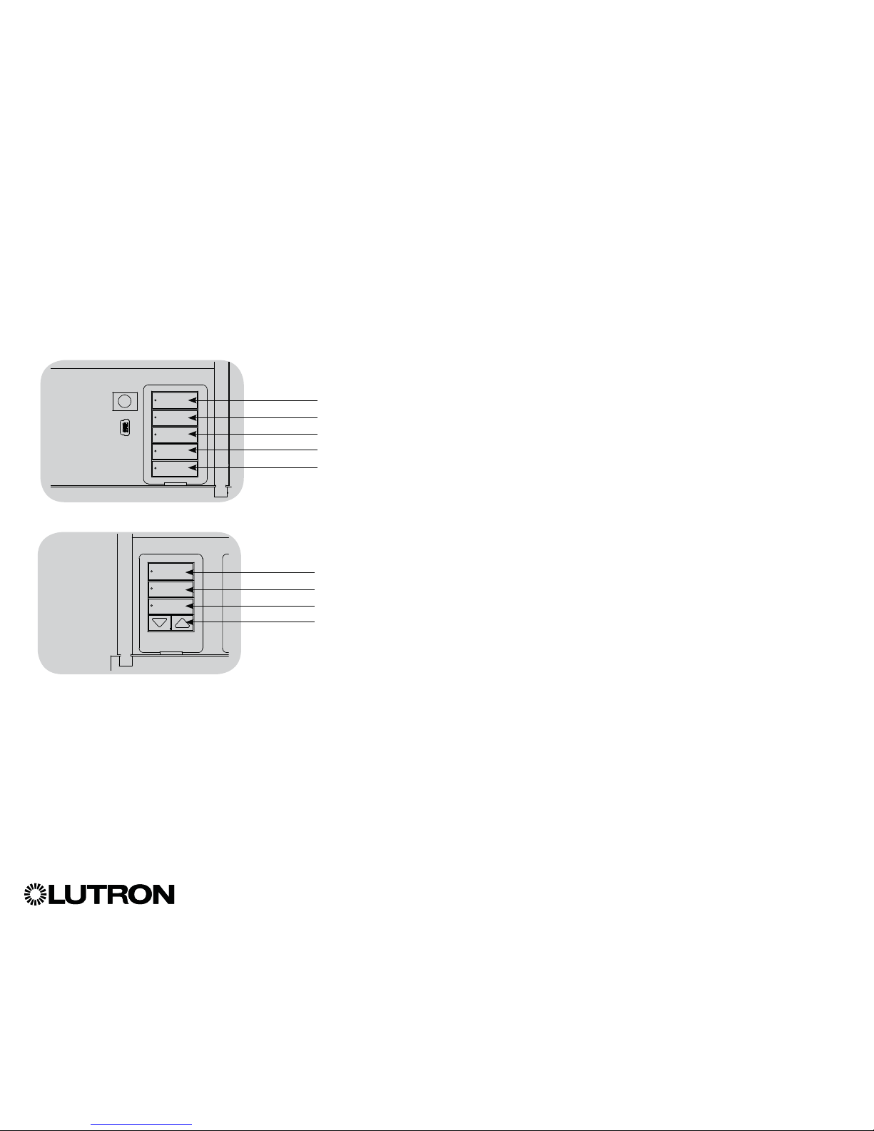
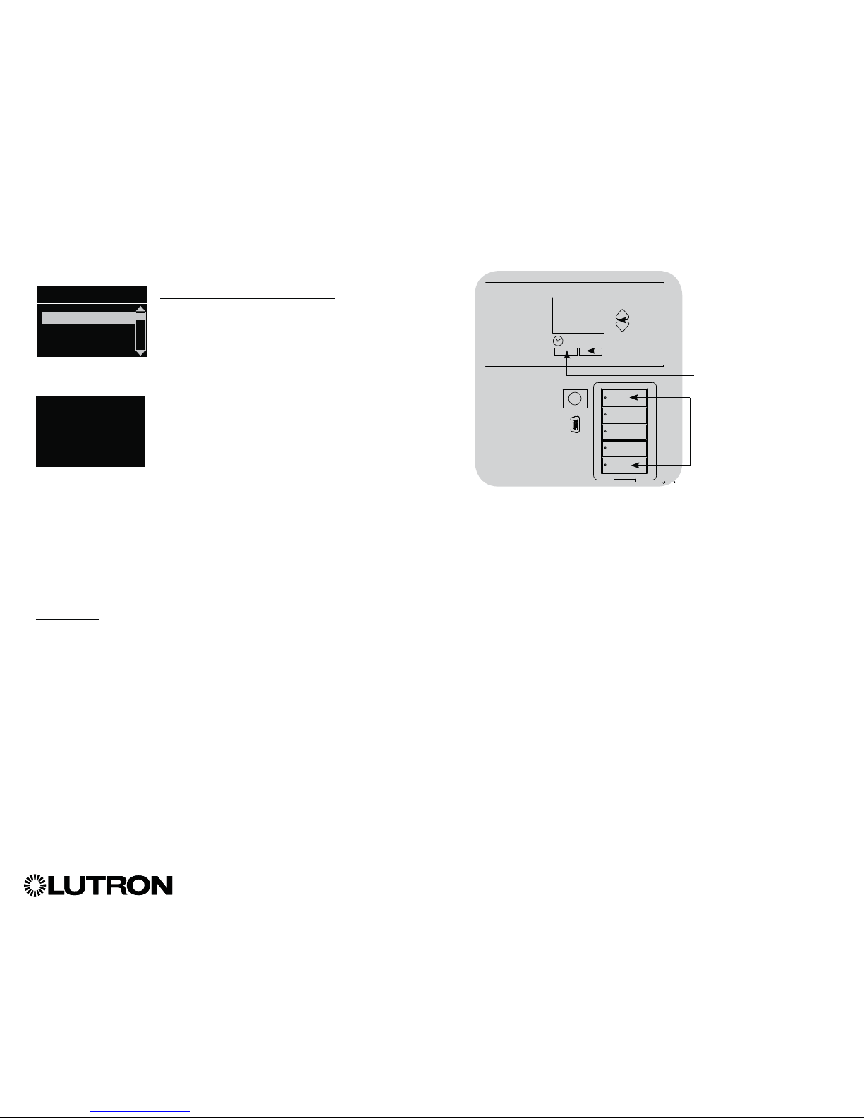
Optional Shade
button groups
Preset and raise/lower
buttons with integral LEDs
(maximum of 3 button
groups)
Zone numbers
Zone raise/lower buttons
Zone LEDs display current
lighting zone levels
Hinged faceplate
Hinged faceplate
Features and Functions of the GRAFIK Eye® QS Control Unit
Info screen
Displays status or
programming functions
Scene buttons
With integral scene
indicator LEDs
Timeclock button
Displays current
timeclock info
“OK” button
Used for programming
Infrared receiver
For handheld remote use
Master buttons
Temporarily raise and lower
lighting levels on unit
USB Receptacle for PC programming: Micro or Mini B
(To access micro USB receptacle, pull down to remove
lower hinged faceplate)
Page 4
®
GRAFIK Eye® QS Control Unit Installation and Operation Guide 4
Wiring the GRAFIK Eye® QS Control Unit
Overview of Line Voltage/Mains Wiring
1234
12
ABC
123456LN
12 AWG (4.0 mm2)
each terminal
120 - 127 V~
or
220 - 240 V~
Distribution
Panel
Line Voltage/Mains
Cables and Load Wiring
123456LN
Incandescent load
Load controlled
by power module
or interface
Terminal labels:
L: Hot/Live
N: Neutral
: Ground
1-6: Dimmed/Switched
line voltage outputs
Power module
or interface
Page 5
®
GRAFIK Eye® QS Control Unit Installation and Operation Guide 5
Wiring the GRAFIK Eye® QS Control Unit (continued)
Line Voltage Wiring Details
• Use properly certified cable for all line
voltage/mains cables.
• Proper short-circuit and overload
protection must be provided at the
distribution panel. You can use up to a
20 A circuit breaker for your installation.
• Install in accordance with all local and
national electrical codes.
• IEC PELV/NEC
® Class 2 terminals may
be temporarily unplugged for ease of IR,
occupancy sensor, and control wiring.
• Notice: Risk of damage to unit. Do not
connect line voltage/mains cable to IEC
PELV/NEC
® Class 2 terminals.
Step 1: Install wallbox. Mount a 3½ in
(89 mm) deep 4-gang U.S. wallbox on a
dry, flat indoor surface that is accessible
and allows for system programming and
operation. Allow at least 4½ in (110 mm)
clearance above and below the faceplate
to ensure proper heat dissipation. Allow
1 in (25 mm) for faceplate overhang on
all sides.
Note: 4-gang wallbox available from
Lutron; P/N 241400.
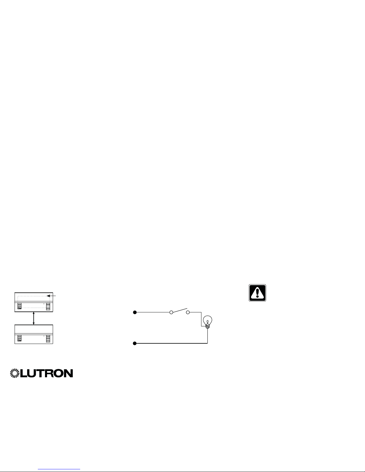
Step 2: Test load wiring.
• Turn power OFF at the circuit breaker or
fuse box.
• Connect a standard light switch between
the live lead and load wire to test the
circuit.
• Turn power ON and check for short or
open circuits. If load does not operate,
the circuit is open. If the circuit breaker
trips (fuse blows or opens), a load short
may exist. Correct short or open circuits
and test again.
`
Step 3: Check control unit wiring.
•
Earth/ground terminal connection must
be made as shown in line voltage wiring
diagrams.
•
Do not mix different load types on the
same zone.
• Follow all local and national electrical
codes when installing IEC PELV/
NEC
® Class 2 wiring with line voltage/
mains wiring.
WARNING! Shock hazard. May
result in serious injury or death.
Always turn off circuit breaker or
remove main fuse from power line
before doing any work. Before
connecting the loads to the
GRAFIK Eye® QS control unit, test
the loads for short-circuits.
Neutral
Hot/Live
Switch
Load
LUTRON
LUTRON
Faceplate overhangs
wallbox on all sides;
allow 1 in (25 mm)
4` in
(110 mm)
Page 6
®
GRAFIK Eye® QS Control Unit Installation and Operation Guide 6
Wiring the GRAFIK Eye® QS Control Unit (continued)
Line Voltage Wiring Details
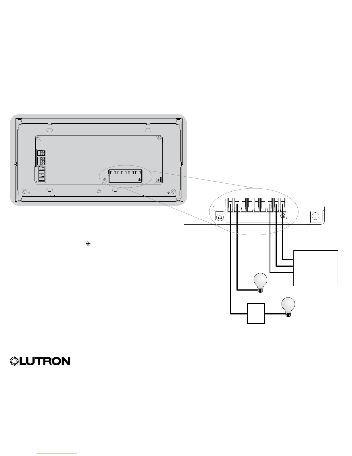
Step 4: Connect line voltage and loads
to control unit.
• Strip 9 in (8 mm) of insulation off the line
voltage/mains cables in the wallbox.
• Connect the line voltage/mains, ground,
and load wires to the appropriate
terminals on the back of the control unit.
L: Hot/Live
N: Neutral
: Ground
Terminals 1-6: Dimmed/Switched
line voltage outputs
9 in
(8 mm)
The recommended installation torque is
5.0 in∙lb (0.6 N∙m) for line voltage/mains
connections and 5.0 in∙lb (0.6 N∙m) for
the earth/ground connection.
Note: See the zone setup section for a
list of compatible load types and
instructions for programming the
GRAFIK Eye
® QS control unit to
properly recognize them.
Notice: Risk of damage to unit. GRAFIK Eye
® QS control units must be in stalled by a
qual i fied electrician in accordance with all applica ble reg u la tions and building codes.
Im prop er wiring can result in dam age to control units or oth er equipment.
Note: To avoid over heat ing and pos si ble damage to equipment, do not install control
units to dim re cep ta cles, mo tor-op erated ap pli ances, or flu o res cent lighting not
equipped with LutronR Hi-lume
®, Eco-10®, Tu-Wire®, electron ic dim ming ballasts, or
other devices approved for your location. In dimmed mag net ic low-voltage cir cuits,
you can pre vent trans former overheating and failure by avoid ing excessively high
current flow. Do not op erate control units with any lamps re moved or burned out;
re place any burned out lamps imme di ate ly; use only transform ers that in cor po rate
thermal pro tection or fused pri ma ry wind ings. Control units are de signed for res i den tial
and commercial use, for indoor use only.
Page 7
1234
12
ABC
123456LN
Contact Closure Input Wiring
24 V- 50 mA
For settings, see CCI Mode Setup.
®
GRAFIK Eye® QS Control Unit Installation and Operation Guide 7
1234
12
ABC
Example:
Occupancy sensor
(maximum 1)
1: COM
2: 24 V-*
3: MUX
4: MUX
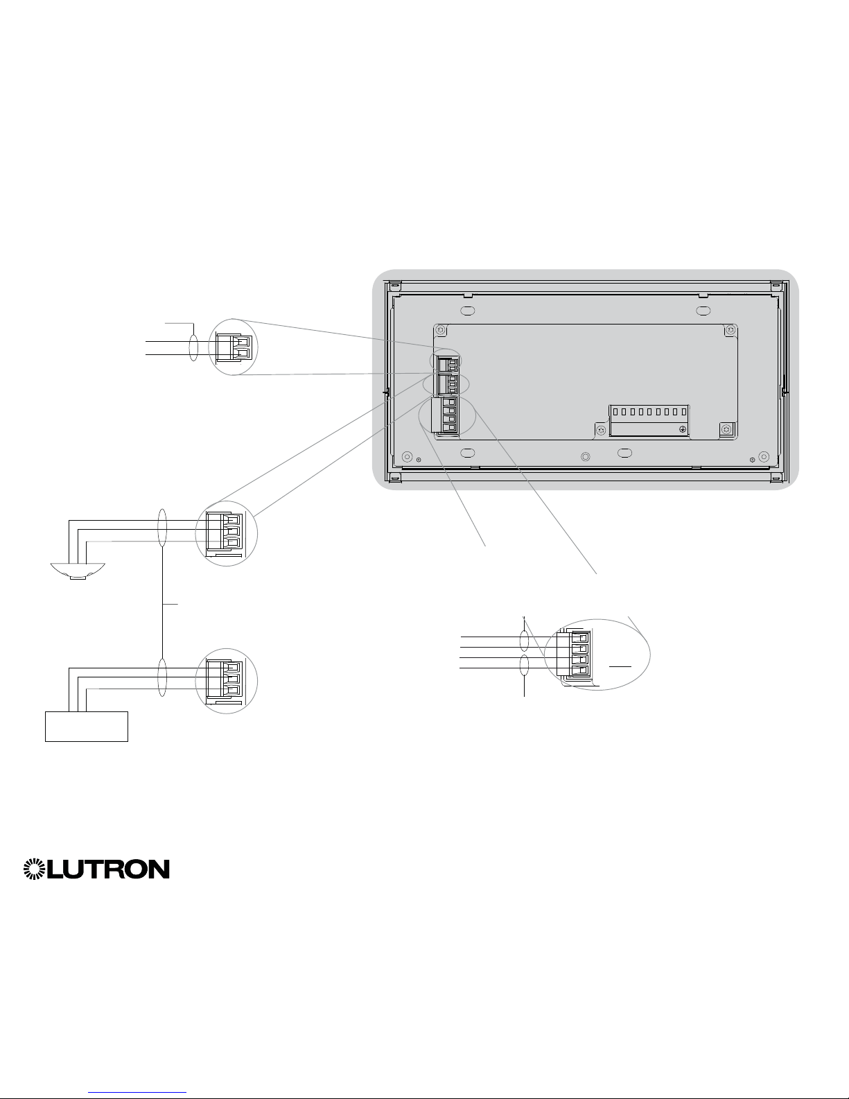
Wiring the GRAFIK Eye® QS Control Unit (continued)
Overview of IEC PELV/NEC® Class 2 Wiring
IR Wiring
From external
IR connection
(by others)
18 AWG (1.0 mm2)
each terminal
18 AWG (1.0 mm2)
each terminal
1: IR DATA
2: IR COM
A: CCI SIG
B: 24 VC: CCI COM
To control stations,
shades, or other
GRAFIK Eye
® QS
control units
Data (terminals 3 and 4):
Twisted, shielded pair 22 AWG (0.5 mm2)
each terminal
* Do not connect terminal 2
between any GRAFIK Eye
®
QS control unit and any other
power supply, including another
GRAFIK Eye
® QS control unit.
Refer to the QS Link Power Draw
Units specification submittal
(LutronR P/N 369405) for more
information concerning PDUs.
ABC
Example:
Emergency lighting interface (maximum 1)
Note: The GRAFIK Eye
® QS control unit
must be powered by a Normal/Emergency
distribution panel for proper ELI operation.
Refer to the LUT-ELI-3PH Installation Guide
for the complete wiring diagram.
A: CCI SIG
B: 24 VC: CCI COM
LUT-ELI-3PH
Signal
+V Input
Circuit Common
Note: Use appropriate wire connecting devices
as specified by local codes.
QS Link Control Wiring
24 V- 100 mA
Common and power (terminals 1 and 2):
Two 18 AWG (1.0 mm2) each terminal (for link <500 ft/153 m)
Two 12 AWG (4.0 mm2) each terminal (for link 500-2000 ft/153-610 m)
Page 8
• System communication uses IEC PELV/NEC®
Class 2 wiring.
• Follow all local and national electrical codes when
installing IEC PELV/NEC® Class 2 wiring with line
voltage/mains wiring.
• Each terminal accepts up to two 18 AWG (1.0 mm
2
)
wires.
• Total length of control link must not exceed
2000 ft (610 m).
• Make all connections in the control unit’s wallbox.
• Wiring can be T-tapped or daisy-chained.
• IEC PELV/NEC® Class 2 24 V- 150 mA.
System Limits
The QS wired communication link is limited
to 100 devices or 100 zones.
The GRAFIK Eye® QS control unit supplies
3 Power Draw Units (PDUs) on the QS link. Refer
to the QS Link Power Draw Units specification
submittal (LutronR P/N 369405) for more information
concerning Power Draw Units.
®
GRAFIK Eye® QS Control Unit Installation and Operation Guide 8
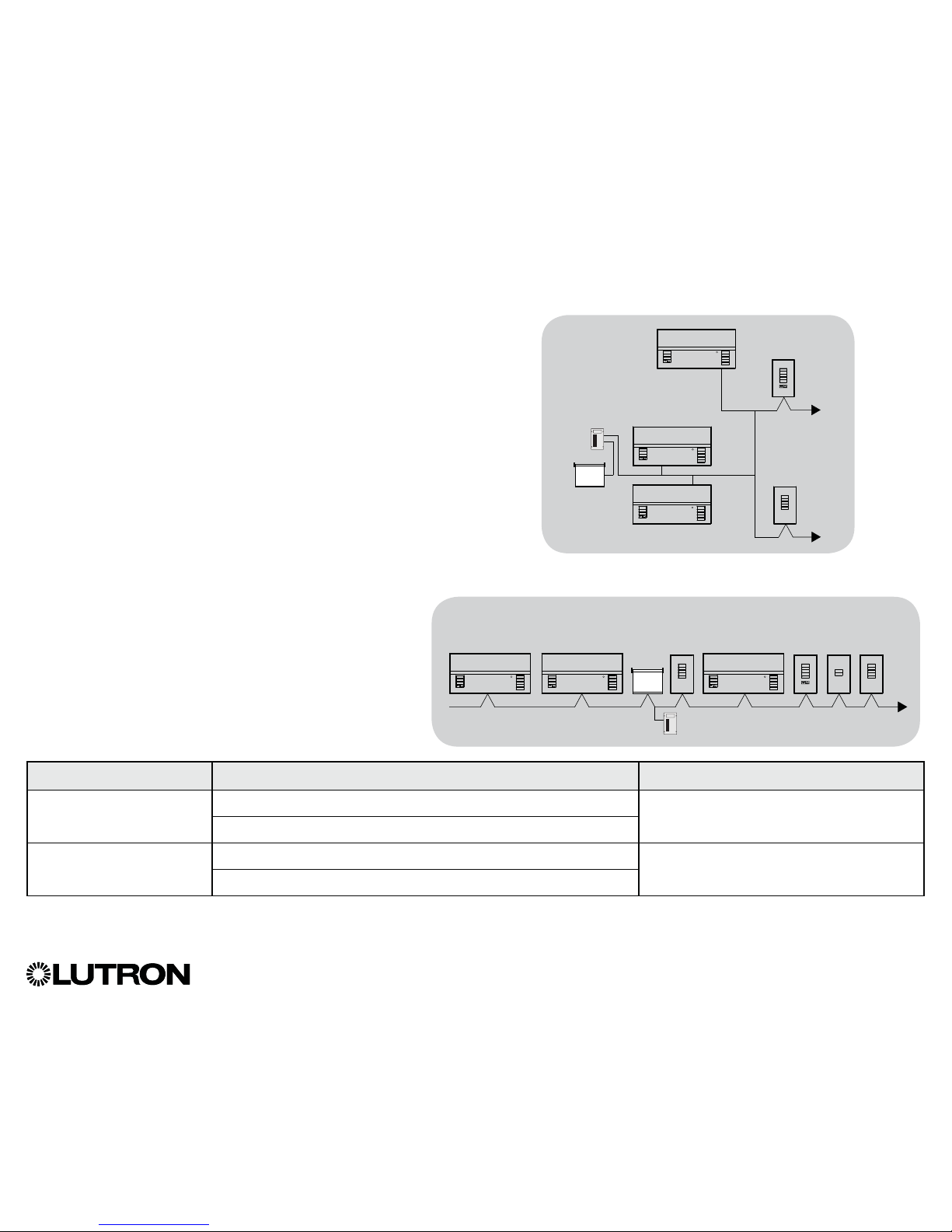
Wiring the GRAFIK Eye® QS Control Unit (continued)
QS Link Control Wiring Details
QS smart
power
panel
LUTRON
LUTRON
LUTRON
LUTRON
LUTRON
T-Tap Wiring Example
GRAFIK Eye® QS
control unit
Sivoia
® QS
shade/drape
seeTouch
® QS
wallstation
LUTRON
LUTRON
LUTRON
LUTRONLUTRON
LUTRON
LUTRON
GRAFIK Eye® QS
control unit
Sivoia
®
QS
shade/
drape
seeTouch
® QS
wallstations
Daisy-Chain Wiring Example
QS smart
power panel
GRAFIK Eye
® QS
control unit
Wire Sizes (check compatibility in your area)
QS Link Wiring Length Wire Gauge LutronR Cable Part Number
Less than 500 ft (153 m) Power (terminals 1 and 2); 1 pair 18 AWG (1.0 mm
2
) GRX-CBL-346S (non-plenum)
GRX-PCBL-346S (plenum)
Data (terminals 3 and 4); 1 twisted, shielded pair 22 AWG (0.5 mm2)
Up to 2000 ft (610 m) Power (terminals 1 and 2); 1 pair 12 AWG (4.0 mm2) GRX-CBL-46L (non-plenum)
GRX-PCBL-46L (plenum)
Data (terminals 3 and 4); 1 twisted, shielded pair 22 AWG (0.5 mm2)
Notes:
• For more information regarding LutronR cable specifications, please see LutronR P/N 369596 and P/N 369597 at www.lutron.com
• For wire runs over 2000 ft (610 m), please contact LutronR Technical Support
Page 9
®
GRAFIK Eye® QS Control Unit Installation and Operation Guide 9
1234
12
ABC
4
3
2
1
4
3
2
1
4
3
2
1
4
3
2
1
123456LN
Wiring the GRAFIK Eye® QS Control Unit (continued)
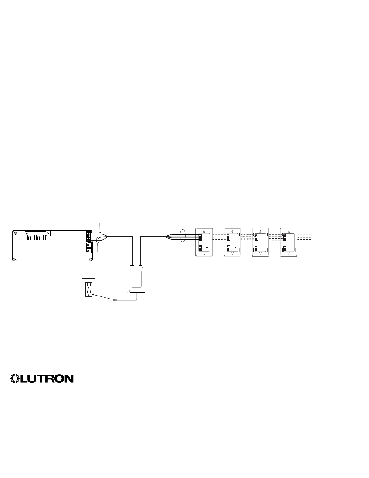
Powering More Than 3 Wallstations Example
• The +24 VDC wire from the power supply
connects to QS link terminal 2 on all of
the wallstations it is powering. This wire
does not connect to terminal 2 on the
GRAFIK Eye
® QS control unit.
The GRAFIK Eye
® QS control unit can power up to 3 seeTouch® wallstations. An external 24 V- power supply is required to power
more than 3 wallstations.
To power source
QSPS-P1-1-50
(powers up to 8 seeTouch
® QS
wallstations)
• The Common wire from the power
supply connects to QS link terminal 1
on all of the wallstations it is powering
and terminal 1 on the GRAFIK Eye
® QS
control unit.
GRAFIK Eye® QS control unit
(rear view)
1 twisted pair
22 AWG
(0.5 mm
2
)
LutronR cable
GRX-CBL-346S-500 (non-plenum) or
GRX-PCBL-346S-500 (plenum)
seeTouch
® QS wallstations
(1) 18 AWG
(1.0 mm
2
)
Common
• The communication signals on the QS
link (terminals 3 and 4) connect from
the wallstations to the GRAFIK Eye
® QS
control unit on twisted, shielded cable
just as when an additional power supply
is not being used. Control unit shown in
rear view.
Page 10
®
GRAFIK Eye® QS Control Unit Installation and Operation Guide 10
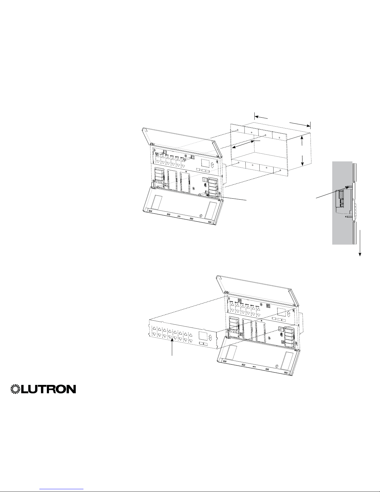
Completing Installation of the GRAFIK Eye® QS Control Unit
1. Mount the control unit in the wallbox as
shown using the four screws pro vid ed.
Note: Follow all local and national
electrical codes when installing IEC
PELV/NEC
® Class 2 wiring with line
voltage/mains wiring.
2. Verify installation:
• Restore power.
• Press the top scene button. The LED
will light.
• Press the zone raise and lower buttons.
Make sure the control unit is dimming all
connected loads.
3. Apply the protective overlay to the
control unit.
Note: When tightening mounting
screws, make sure that the hinged
cover and faceplate will open fully,
as shown.
Wall
7.9 in
(200 mm)
3.5 in
(87 mm)
3.75 in
(95 mm)
Protective overlay
(apply after installation)
Note: To access micro USB
receptacle, pull down to remove
lower hinged faceplate.
Page 11
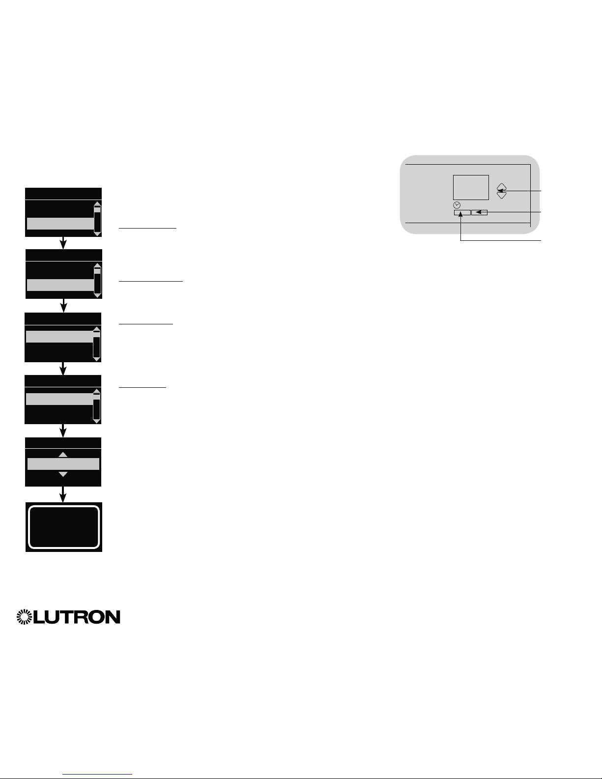
OK
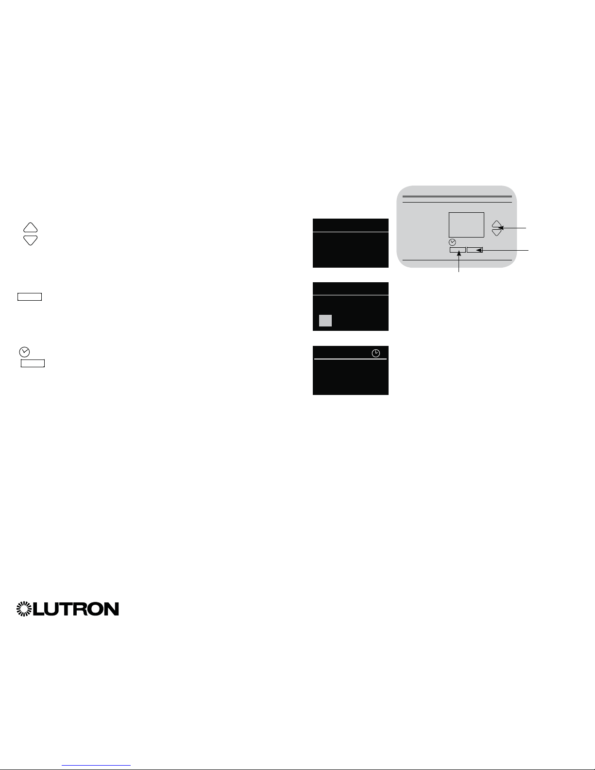
The info screen turns off 30 seconds after the last button press or
completion of the last scene change. See example screens below.
The Master buttons activate the info screen. These buttons
temporarily raise or lower all dimmable lights (except those
programmed as unaffected in the current scene). Adjustments are
temporary and do not affect scene programming.
Note: Master buttons affect all zones.
The “OK” button activates the info screen (when off), which then
shows the current scene and its fade time.
In “Save Always”
mode, it allows fade time adjustment. In “Save by OK” mode,
pressing a second time allows zone adjustment; pressing a
third time allows fade adjustment.
The Timeclock button activates the info screen and displays the
current time and the next event scheduled to occur. Pressing
a second time displays the time, date, and afterhours status.
Pressing a third time displays location and sunrise/sunset times.
Pressing a fourth time displays the language selection screen.
Pressing once more returns to the first screen.
®
GRAFIK Eye® QS Control Unit Installation and Operation Guide 11
Scene 1
Master raise
Master lower
General Functionality
OK
Scene 1
Adjust fade
3 seconds
11:23 AM Fri
Next: 5:00 PM
Scene 1
Master buttons
“OK” button
Timeclock
(back) button
Page 12
Pre-Programmed Button Functionality
®
GRAFIK Eye® QS Control Unit Installation and Operation Guide 12
Scene Button Pre-Programming
for Dimmable Loads
Scene 1: All zones to 100%
Scene 2: All zones to 75%
Scene 3: All zones to 50%
Scene 4: All zones to 25%
All zones Off
Shade Button Pre-Programming
for Sivoia® QS shades
All shades fully open
All shades to 50%
All shades fully closed
Lower/Raise all shades
(Applies only to units with shade keypads)
The GRAFIK Eye® QS control unit controls most lighting loads without special
programming. Each unit ships with pre-programmed default settings for the scene and
shade buttons. For load types other than those shown below (dimmable or non-dim),
assign the load type before proceeding. See the scene setup section for instructions on
changing scene settings.
Page 13
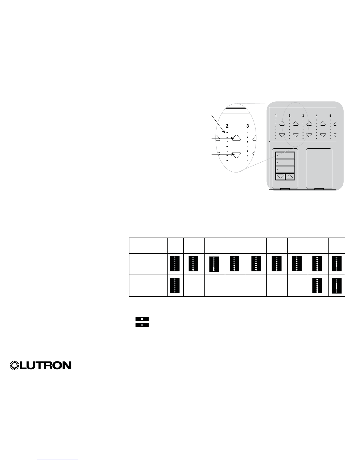
Zone Button Operation
Each zone column (LEDs and buttons)
represents one zone of lights. Pressing
any button on a column turns on the info
screen and displays the zone’s current
light level and current energy savings.
Pressing the raise and lower buttons on a
zone causes different actions depending
on zone type (see below).
Dimmable zones:
• Press and hold to raise/lower all lights in a
zone; release to stop
• Press raise or lower to stop a zone that is
fading
• Raising lights from off to full on or lowering
from full on to off takes 5 seconds
• Press raise and lower simultaneously to
toggle between full on and off
• Press and hold lower for 6 seconds after
the zone has gone to 0% light level to
set the zone as unaffected in the current
scene. The zone will not change when this
scene is initiated, and the Master buttons
will not raise/lower the zone in this scene.
Non-dim zones:
• Press raise to turn zone on
• Press lower to turn zone off
Note: To set zone types, see the zone
setup section.
®
GRAFIK Eye® QS Control Unit Installation and Operation Guide 13
Zone Raise
Zone Lower
Legend:
UA = Unaffected (lights are not affected by
scene button or Master buttons)
LED on
LED off
Zone LEDs
LEDs indicate
light level
(see below)
Zone LED Displays for % of Lighting Levels
Light Level
(%)
Off 1–17 18-33 34-49 50-66 67-82 83-99 On/
100
UA
Dimmable
Load Types
Non-Dim
Load Types
Page 14
Entering and Exiting Programming Mode
Entering programming mode:
Press and hold the top and bottom scene
buttons simultaneously for 3 seconds. The
LEDs in the scene buttons will scroll from
top to bottom, confirming that you are in
programming mode, and the info screen will
display the main menu.
Exiting programming mode:
Press and hold the top and bottom scene
buttons simultaneously for 3 seconds. The
info screen will go to Scene 1.
Navigating Menus in Programming Mode
Master Buttons
The Master buttons allow you to move through the menu
choices. The current choice is highlighted on the info screen.
OK Button
The “OK” button chooses the current highlighted menu choice.
This will either take you to the next menu or accept a setting you
have selected. When the screen displays a Yes/No question, the
“OK” button is “Yes.”
Timeclock Button
The Timeclock button functions as a “back” button during
programming mode. Pressing the Timeclock button takes
you back one step in the current menu. Pressing it repeatedly
will eventually return you to the main menu, but will not exit
programming mode. When the screen displays a Yes/No
question, the Timeclock button is “No.”
®
GRAFIK Eye® QS Control Unit Installation and Operation Guide 14
Programming Mode
OK
Press and hold the top and
bottom buttons for 3 seconds
to enter or exit programming
mode
Master buttons
“OK” button
Timeclock (back) button
Main menu
Scene setup
Timeclock
Scene 1
Fade time
3 seconds
Page 15
®
GRAFIK Eye® QS Control Unit Installation and Operation Guide 15
Wireless Mode
Many models of the GRAFIK Eye® QS control unit support wireless communication with
other Lutron® products. This feature allows for easy integration of wireless sensors,
keypads, remotes, and shades for single-room wireless applications, as well as
compatibility with other LutronR wireless systems such as RadioRA® 2.
(See the RadioRA® 2 Setup Guide; LutronR P/N 044254.)
Units supporting wireless communication are labeled “GRAFIK Eye
® QS Wireless” on
the front label of the unit.
The wireless feature of the GRAFIK Eye
® QS Wireless control unit has 3 modes of
operation.
• Ignore Programming (default): The GRAFIK Eye
® QS Wireless control unit will only
respond to normal operation commands from wireless devices associated while in
“Enabled” mode.
• Disabled: Use for wired-only systems.
• Enabled (30 minutes): The GRAFIK Eye
® QS Wireless control unit will respond to any
programming commands from nearby LutronR QS wireless (and compatible) products.
The GRAFIK Eye® will automatically revert to “Ignore Programming” mode if there is no
activity for 30 minutes.
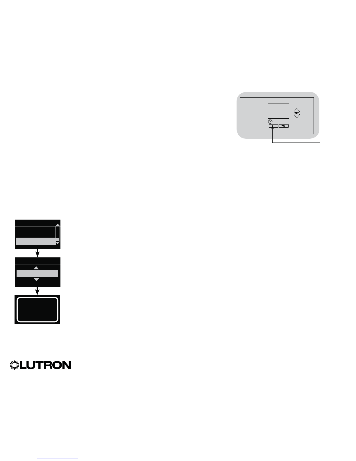
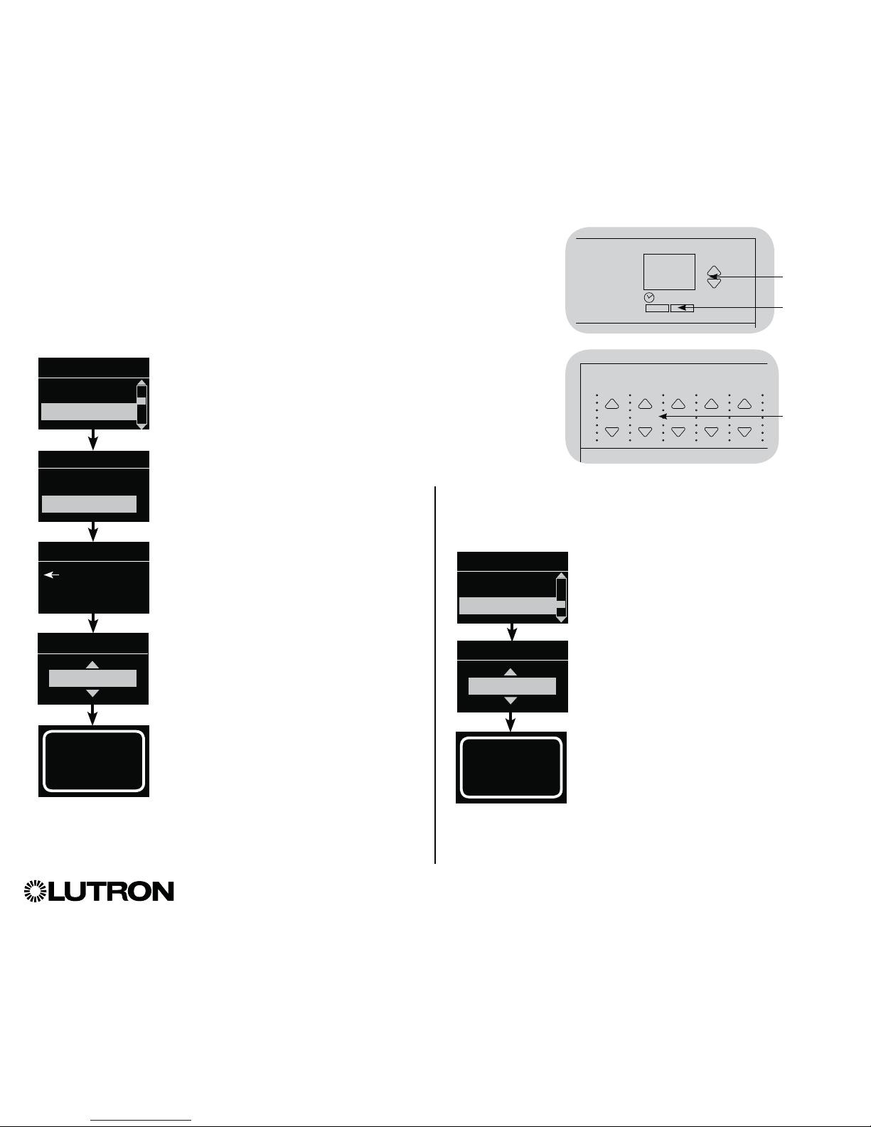
Changing the wireless mode of the GRAFIK Eye
® QS Wireless control unit:
1. Enter programming mode.
2. Use the Master buttons to highlight “Wireless Mode” and press
the “OK” button to accept.
3. Use the Master buttons to highlight the desired wireless mode,
and press the “OK” button to accept.
4. The info screen will display a confirming “Saved” message.
5. Exit programming mode.
Notes
• The wireless signal has a range of 30 ft (9 m) through standard
construction or 60 ft (18 m) line of sight.
• When used within a RadioRA
® 2 system, the wired QS link on the
GRAFIK Eye® QS control unit is disabled, and certain features
that do not pertain to RadioRA® 2 are not accessible.
Wireless Mode
Enabled (30 minutes)
Saved
Saved
Main menu
Shade labels
Wireless Mode
FCC Information
Changes or modifications not expressly approved
by Lutron Electronics Co. could void the user’s
authority to operate this equipment.
Note: This equipment has been tested and
found to comply with the limits for a Class B
digital device, pursuant to Part 15 of the FCC
rules. Operation is subject to the following: (1)
This device may not cause harmful interference,
and (2) this device must accept any interference
received, including interference that may cause
undesired operation.
These limits are designed to provide
reasonable protection against harmful interference
in a residential and commercial installation. This
equipment generates, uses, and can radiate
radio frequency energy and, if not installed and
used in accordance with the instructions, may
cause harmful interference to radio or television
reception. However, there is no guarantee
that interference will not occur in a particular
installation. If this equipment does cause harmful
interference to radio or television reception, which
can be determined by turning the equipment off
and on, the user is encouraged to try to correct
the interference by one or more of the following
measures:
• Reorient or relocate the receiving antenna.
• Increase the separation between the equipment
and receiver.
• Connect the equipment into an outlet on a
circuit different from that to which the receiver is
connected.
• Consult the dealer or an experienced radio/TV
technician for help.
OK
Master
buttons
“OK”
button
Timeclock
(back) button
Page 16
®
GRAFIK Eye® QS Control Unit Installation and Operation Guide 16
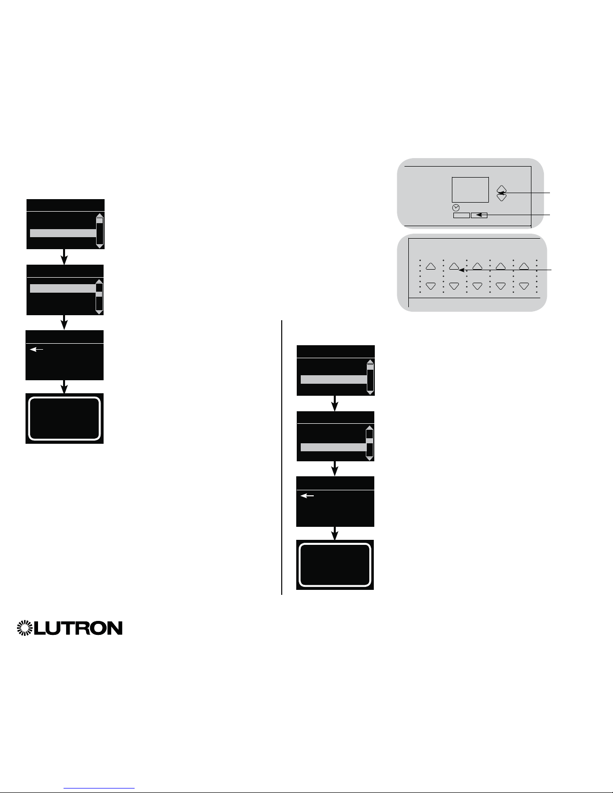
Assigning Load Types
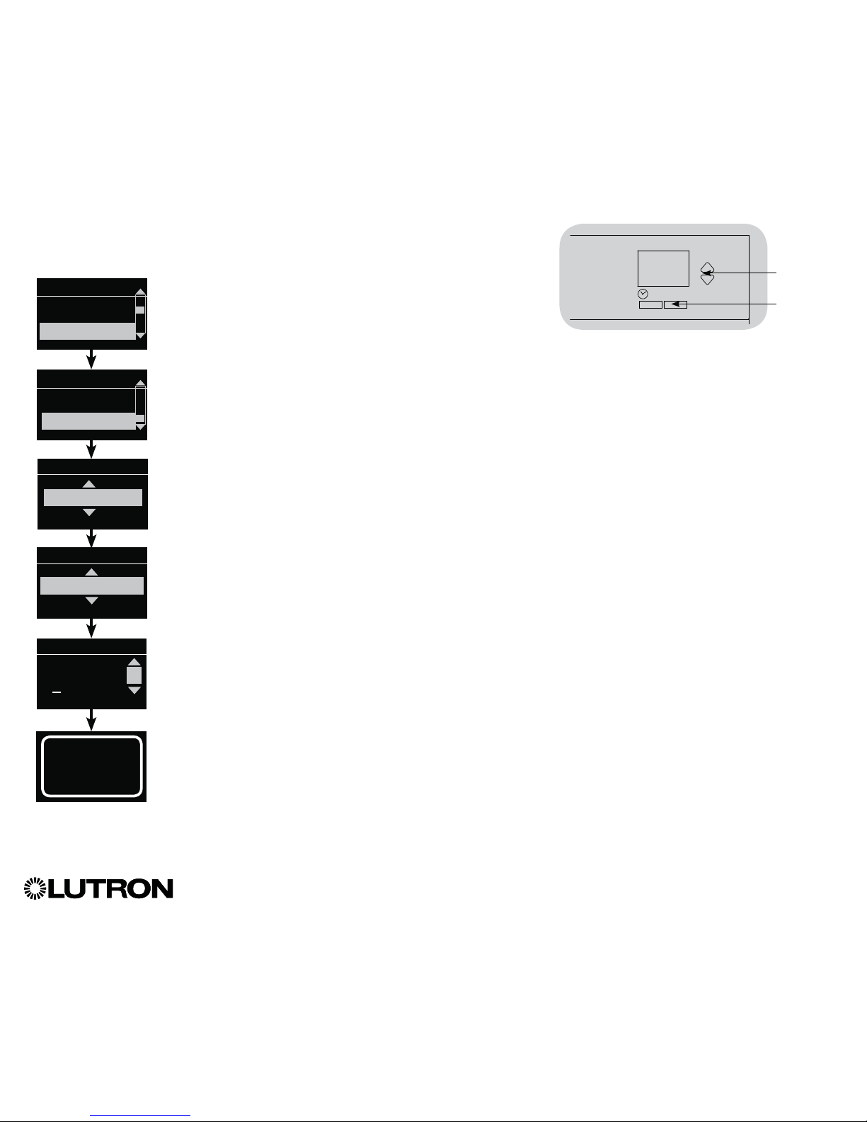
1. Enter programming mode.
2. Use the Master buttons to highlight
“Zone setup” and press the
“OK” button to accept.
3. Use the Master buttons to highlight
“Load type.” Press the “OK” button
to accept. See “Setting Load Types”
table on the next page.
4. Use the zone raise/lower buttons
to choose the load type for that
zone. See the list on the next page
for supported load types. Press the
“OK” button to accept.
5. The info screen will confirm that
your load type has been saved.
6. Exit programming mode.
Zone Setup
OK
Master
buttons
“OK” button
Main menu
CCI Setup
Zone setup
1 2 3 4 5 6
Use the
zone
raise/lower
buttons to
choose the
load type for
that zone.
Zone Setup
Non-Dim Load Type
Load Type
Set zones
Saved
Load Type
Assigning Non-Dim Load Types
Zones assigned to non-dim loads have five available configurations:
• LOFO: Last On, First Off
• FOFO: First On, First Off
• FOLO: First On, Last Off
• LOLO: Last On, Last Off
• 60/40: On at 60%, off at 40%
Scenes made up of both dim and non-dim
load types will toggle the non-dim loads before
the dim loads in a “First” on/off configuration,
and after the dim loads in a “Last” on/off
configuration.
1. Enter programming mode.
2. Use the Master buttons to highlight “Zone
setup” and press the “OK” button to accept.
3. Use the Master buttons to highlight “Non-Dim
Load type.” Press the “OK” button to accept.
See “Setting Load Types” table on the
next page.
4. Use the zone raise/lower buttons to choose
the non-dim load type for that zone. (Zones
not programmed as non-dim will be displayed
as Unaffected.) Press the “OK” button to
accept.
5. The info screen will confirm that your load type
has been saved.
6. Exit programming mode.
Main menu
CCI Setup
Zone setup
Zone Setup
Load Type
Load Type
Set zones
Saved
Non-Dim Load Type
Page 17
®
GRAFIK Eye® QS Control Unit Installation and Operation Guide 17
Zone Setup (continued)
Load Type Notes
• All electronic low-voltage
(ELV) lighting used with an
interface must be rated for reverse
phase control dimming. Before
installing an ELV light source,
verify with the manufacturer that
their transformer can be dimmed.
When dimming, an ELV interface
(such as the PHPM-PA-DV-WH)
must be used with the control
unit.
• For all DMX or RGB/CMY DMX
lighting, an external DMX interface
(such as the QSE-CI-DMX) must
be used with the control unit.
• Maximum total lighting load for
Lutron
® Tu-Wire® and Advance
Mark X® electronic dimming
ballasts (120 to 127 V~ only)
must not exceed 6 A per zone
or 16 A per unit.
Zone ratings:
• Not all zones must be connected;
however, connected zones must
have a minimum load:
120 - 127 V~: 25 W
220 - 240 V~: 40 W
• Maximum zone loads:
120 - 127 V~: 800 W
220 - 240 V~: 1200 W
• Maximum total lighting load for
magnetic low-voltage (MLV) varies
by input voltage:
120 - 127 V~: 800 VA / 600 W
220 - 240 V~: 1200 VA / 960 W
LUTRON
LUTRON
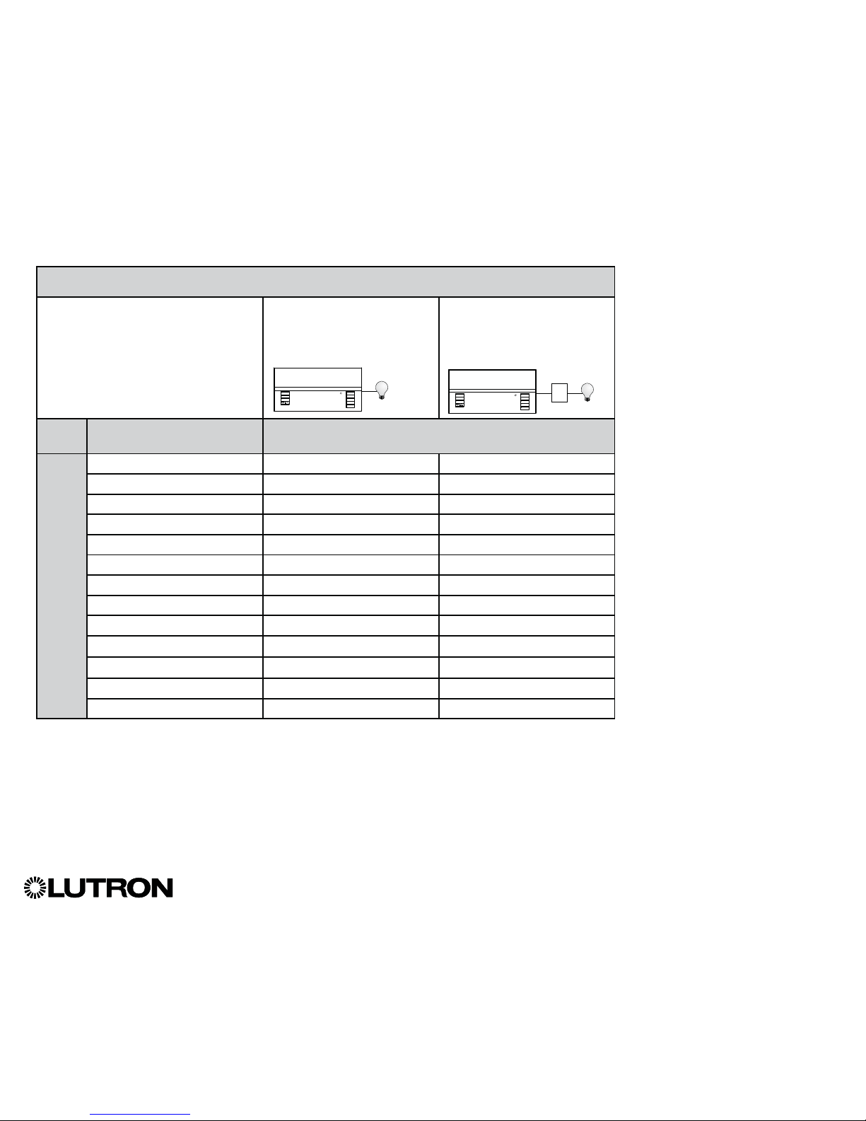
Setting Load Types
Direct control via
GRAFIK Eye
® QS
control unit
Control via
power module or
interface
Fixture load type Choose this load type from the menu
on the GRAFIK Eye
® QS control unit:
Zones
1 – 6
Incandescent Incandescent Power module
MLV (magnetic low-voltage) MLV Power module
ELV (electronic low-voltage) — Power module
Hi-Lume
®/Eco-10® — Fluorescent module
0-10 V — Fluorescent module
Non-dim lighting loads Non-dim Non-dim
Neon/Cold cathode Neon, CC Neon, CC
Tu-Wire® Tu-Wire Tu-Wire
Advance Mark X® Tu-Wire Tu-Wire
DMX — DMX
RGB/CMY DMX — RGB/CMY DMX
Cree LR4/LR6 LED Cree LR4/LR6 LED Fluorescent module
LED Incandescent* Power module
* Use incandescent load type unless otherwise specified in the LED product selection tool available at www.lutron.com/ledtool.
Power
module or
interface
Page 18
Setting Minimum Level (optional)
Some local regulations specify a minimum lighting level for
dimming zones in occupied buildings. If this pertains to you,
follow these steps to set up your minimum lighting level.
1. Enter programming mode and select
“Zone setup,” then “Min level.” Press the
“OK” button to accept.
2. Use the Master buttons to highlight “Off”
if you want your lights to go all the way
off at their minimum light level, or “10%”
if you want that to be the minimum light
level. Press the “OK” button to accept.
Note: Non-dim loads will turn off
regardless of the minimum level
setting.
3. The info screen will confirm that your
minimum level has been saved.
4. Exit programming mode.
®
GRAFIK Eye® QS Control Unit Installation and Operation Guide 18
Zone Setup (continued)
Setting High End or Low End Trim
• If you are unsure about appropriate high and low end settings,
please contact LutronR Technical Support for assistance.
• High and low end trim settings limit the maximum and minimum
output of a dimming zone. Trim levels are set automatically when
the load type is programmed.
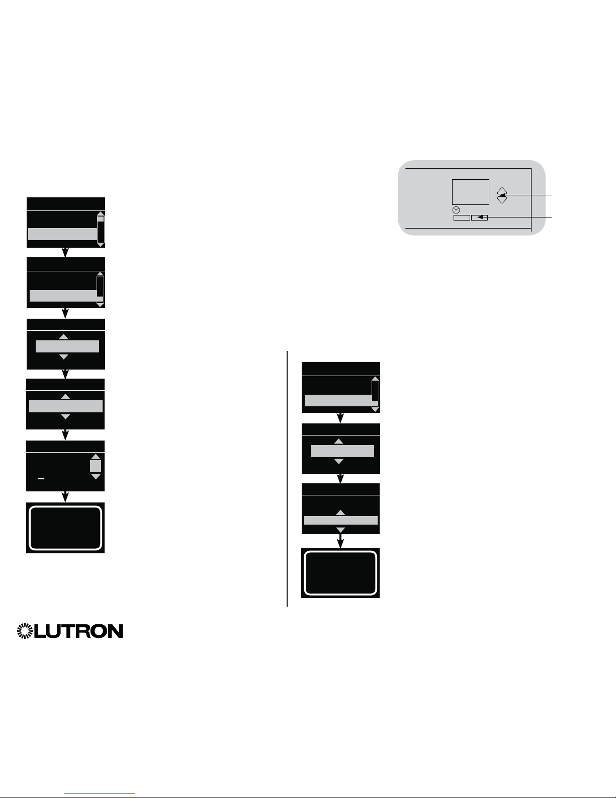
1. Enter programming mode.
2. Use the Master buttons to highlight “Zone
setup” and press the “OK” button to
accept.
3. Use the Master buttons to highlight “High
end” or “Low end” (this example shows
low end). Press the “OK” button to accept.
4. Use the zone raise/lower buttons to set
the high end or low end trim for that
zone. The info screen will display each
zone number and percentage as you
adjust it. Press the “OK” button to accept.
5. The info screen will confirm that your
setting has been saved.
6. Exit programming mode.
Main menu
CCI Setup
Zone setup
High end
Zone 2
Low end
Set zones
Low end
OK
Master
buttons
1 2 3 4 5 6
Use the
zone
raise/lower
buttons to
set the high
end or low
end trim for
that zone.
“OK”
button
10%
Min level
Off
Zone setup
Low end
Min level
Zone setup
Saved
Saved
Page 19
®
GRAFIK Eye® QS Control Unit Installation and Operation Guide 19
Zone Setup (continued)
Labeling a Zone (optional)
1. Enter programming mode.
2. Use the Master buttons to highlight “Zone setup” and press
the “OK” button to accept.
3. Use the Master buttons to highlight “Label” and press the
“OK” button to accept.
4. Use the Master buttons to change the zone number to your
desired zone. Custom zone labels will appear if previously set.
Press the “OK” button to accept.
5. Use the Master buttons to highlight “Custom” and press the
“OK” button to accept. Or, highlight “Default” to return the
zone label to the default (e.g., Zone 1).
6. Use the Master buttons to scroll through the characters
(lowercase and uppercase letters, plus numbers 0 through 9).
The character you are currently changing will be underlined
on the screen. Press OK to select the character you want,
then repeat for all available characters. Choose a space (no
character) and press OK for any remaining characters. Press
the “OK” button to accept.
Note: Custom zone labels will always begin with the zone
number and a colon (e.g., 1: Uplights).
7. The info screen will confirm that your name has been saved.
8. Exit programming mode.
Main menu
CCI Setup
Zone setup
Min level
Label zone
Label
Label zone 2
Custom
Label zone 2
1: A
A
1 / 11
OK
Master
buttons
“OK”
button
Zone setup
Zone 2
Saved
Page 20
®
GRAFIK Eye® QS Control Unit Installation and Operation Guide 20
Scene Setup
Setting Zone Levels, Fade Rates, and Shade Group Actions
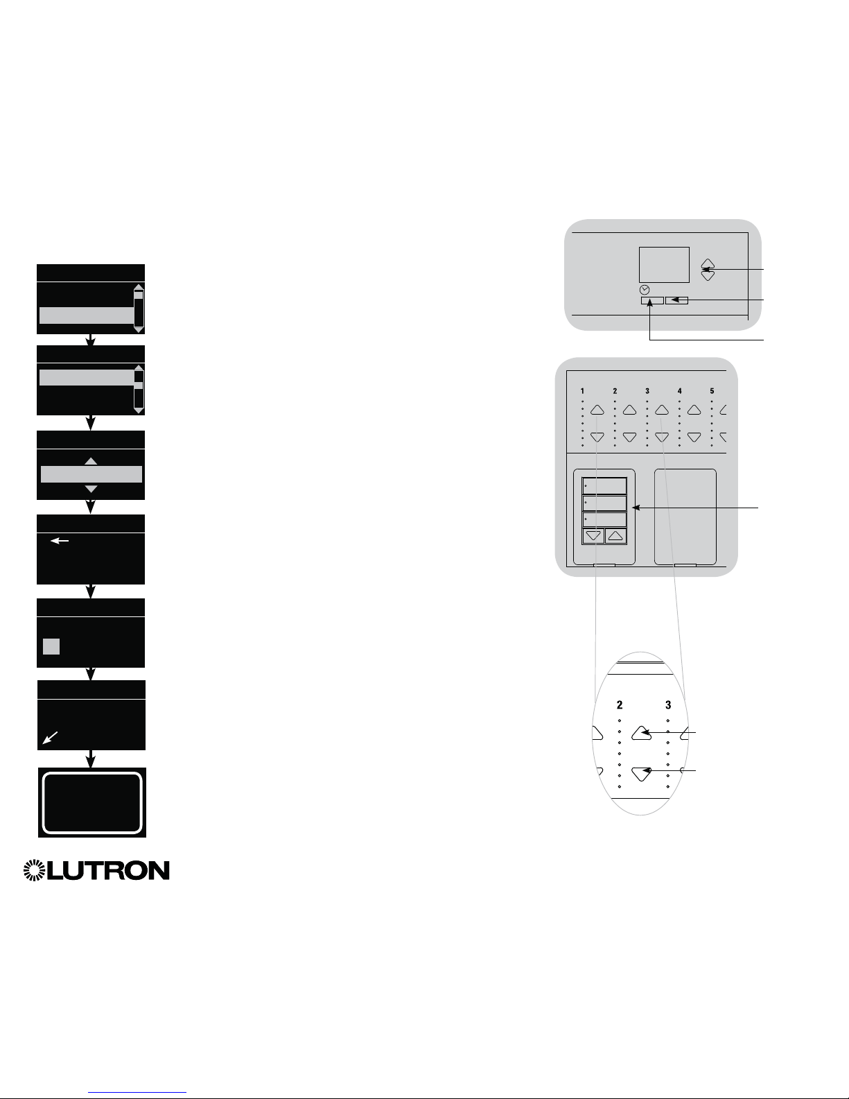
1. Enter programming mode.
2. Use the Master buttons to highlight “Scene setup” and press
the “OK” button to accept.
3. Use the Master buttons to highlight “Levels” to adjust lighting
and/or shade levels. Press the “OK” button to accept. Use the
Master buttons to highlight the scene number of your desired
scene. Press the “OK” button to accept.
4. Set each zone to the desired light level for this scene using
the zone raise/lower buttons. The info screen will display the
zone and percentage as you adjust it.
To set a zone as unaffected, lower the light levels all the way
to off, then hold the zone lower button for 3 seconds. The
screen will display “---” and the three middle LEDs for the
zone will be lit to indicate this zone is unaffected by the scene
(the zone will not change when this scene is initiated).
When all zones are at the desired level, press the “OK” button
to accept.
5. Use the Master buttons to set the fade time for this scene.
Press the “OK” button to accept.
6. Note: This step is applicable only if you have shades on your
system. If you do not have or do not wish to set shade
groups for this scene, press the “OK” button to skip this
step.
Set each shade group to the desired level for this scene.
When all shade groups are at the desired level, press the
“OK” button to accept.
For shade programming, see the section on adjusting shade
settings.
7. The info screen will confirm that your scene has been saved.
8. Exit programming mode.
Main menu
Timeclock
Scene setup
Scene setup
Labels
Levels
Scene 1
Adjust fade
seconds
Scene 1
Set shade
Groups
3 seconds
Scene 1
Set zones
Scene setup
Scene 1
Saved
3
Shade
button group
Zone raise
Zone lower
OK
Master
buttons
“OK”
button
Timeclock
(back) button
Page 21
®
GRAFIK Eye® QS Control Unit Installation and Operation Guide 21
Scene Setup (continued)
Labeling a Scene (optional)
1. Enter programming mode.
2. Use the Master buttons to highlight
“Scene setup” and press the
“OK” button to accept.
3. Use the Master buttons to highlight
“Labels” and press the “OK” button
to accept.
4. Use the Master buttons to highlight
your desired scene. Press the
“OK” button to accept.
5. Use the Master buttons to
highlight “Custom” and press the
“OK” button to accept.
6. Use the Master buttons to scroll
through the characters (lowercase
and uppercase letters, plus numbers
0 through 9). The character you are
currently changing will be underlined
on the screen. Press OK to select
the character you want, then repeat
for all available characters. Choose
a space (no character) and press OK
for any remaining characters. Press
the “OK” button to accept.
7. The info screen will confirm that
your name has been saved.
8. Exit programming mode.
Main menu
Timeclock
Scene setup
Labels
Select scene:
Scene 1
Label scene 1
Custom
Label scene 1
1: A
A
1 / 10
OK
Master
buttons
“OK”
button
Scene setup
Levels
Labels
Saved
Enabling/Disabling Daylighting in a Scene
1. Enter programming mode.
2. Use the Master buttons to highlight “Scene
setup” and press the “OK” button to accept.
3. Use the Master buttons to highlight
“Daylighting” and press the “OK” button to
accept.
4. Use the Master buttons to highlight your desired
scene. Press the “OK” button to accept.
5. Use the Master buttons to select “Enable” or
“Disable.” When daylighting is disabled in a
scene, the GRAFIK Eye
® QS control unit will
not respond to daylight sensors information
when that scene is active.
Press OK to save.
6. Exit programming mode.
Labels
Daylighting
Scene 1
Scene 1
Daylighting
Enable
Scene setup
Labels
Daylighting
Saved
Page 22

®
GRAFIK Eye® QS Control Unit Installation and Operation Guide 22
Setting Save Mode
The Save Mode of the GRAFIK Eye® QS control unit can be adjusted to turn quick
scene programming on and off, or to disable the use of zone and/or scene buttons
for specific applications.
Save Mode Settings
Save by OK (default): Quick scene programming mode; zone
adjustments are temporary until the “OK” button is pressed to
confirm the selection.
Save always: Automatically save changes made to lighting
levels or fade time to Off (Master button changes are
temporary).
Save never: Do not save any temporary changes to lighting
levels or fade time.
Four scenes (typically used for rented spaces): Zone raise/
lower buttons are disabled. Master raise/lower buttons,
wallstations, and IR receiver are still enabled for adjustment
of light level, but these changes are not saved.
Button disable (typically used in a public space): Only the
Timeclock button, IR receiver, and wallstations can be used
to make temporary changes.
Changing the Save Mode
1. Enter programming mode.
2. Use the Master buttons to highlight “Save mode” and press
the “OK” button to accept.
3. Use the Master buttons to highlight the desired save mode.
The save modes are listed and explained below.
4. Press the “OK” button to accept. The info screen will confirm
that your save mode has been saved.
5. Exit programming mode.
Main menu
Scene setup
Save mode
Save mode
Save always
OK
Master
buttons
“OK”
button
Saved
Quick Scene Programming:
“Save by OK” Mode
By default, the GRAFIK Eye® QS control
unit is in “Save by OK” mode, which
allows you to quickly set scenes without
entering program mode.
1. Press the button for the scene you want
to set; its LED will light and the lights will
go to the current settings.
2. Use the zone raise/lower buttons to set
all lights to the desired levels. Press the
“OK” button to select.
3. Set the fade time to the desired length
using the Master buttons, and press the
“OK” button to save.
4. The info screen will confirm that the new
scene settings have been saved.
Notes
• Using the Master buttons to raise or
lower lighting settings is still temporary.
• To set a zone to unaffected (---), press
and hold the zone lower button for
6 seconds after the zone has gone to 0%
light level.
Zone raise/lower buttons
Page 23

®
GRAFIK Eye® QS Control Unit Installation and Operation Guide 23
Contact Closure Input (CCI) Setup
(wired directly to the GRAFIK Eye® QS control unit)
The integral contact closure input (CCI) on the back of the GRAFIK Eye® QS control
unit can be configured as:
Occupancy (default): Allows a wired occupancy sensor to be included in the list of
available sensors when setting up occupancy actions.
Emergency: This setting allows the GRAFIK Eye
® QS control unit to work with a
LUT-ELI-3PH emergency lighting interface. When an emergency situation is detected,
all lights will go to full on, and will not change until the emergency signal is cleared.
Afterhours: Allows the CCI to start and end Afterhours.
Timeclock: Allows the CCI to enable and disable the timeclock.
Lockout: Prevents the user from making any changes to the control unit. The current scene will stay on until the CCI
enables normal operation.
Never Save: Prevents any changes from being saved while the CCI is being used.
Disable CCI: The CCI will have no effect on the system and will not appear on the list of available occupancy sensors
within the sensor setup menu.
Changing the operation of the contact closure input:
1. Enter programming mode.
2. Use the Master buttons to highlight “CCI Setup” and press the “OK” button to accept.
3. Use the Master buttons to highlight “CCI Mode” and press the “OK” button to accept.
4. Use the Master buttons to highlight the mode you wish the CCI to control. Press the “OK” button
to accept.
5. The info screen will confirm that your setting has been saved.
6. Exit programming mode.
CCI Mode
Occupancy
Saved
Saved
Main menu
Save Mode
CCI menu
CCI Type
CCI Setup
CCI Mode
OK
Master
buttons
“OK”
button
Timeclock
(back) button
(continued on the next page)
Page 24

®
GRAFIK Eye® QS Control Unit Installation and Operation Guide 24
Contact Closure Input (CCI) Setup (continued)
(wired directly to the GRAFIK Eye® QS control unit)
The integral contact closure input (CCI) on the back of the GRAFIK Eye® QS control unit
is compatible with either type of contact closure device:
Maintained (default): The GRAFIK Eye® QS control unit will act on both a contact
closure and a contact open/release event.
Example: “CCI Mode” set to “Afterhours.” Contact closure starts “Afterhours.”
Contact open/release ends “Afterhours.”
Momentary: The GRAFIK Eye
® QS control unit will act on only contact closure events.
Example: “CCI Mode” set to “Afterhours.” Contact closure starts “Afterhours.”
Contact open/release has no effect. Second contact closure ends “Afterhours.”
Changing the type of contact closure input:
1. Enter programming mode.
2. Use the Master buttons to highlight “CCI Setup” and press the
“OK” button to accept.
3. Use the Master buttons to highlight “CCI Type” and press the
“OK” button to accept.
4. Use the Master buttons to highlight the type you wish the CCI
to control. Press the “OK” button to accept.
5. The info screen will confirm that your setting has been saved.
6. Exit programming mode.
Note: The “Emergency CCI Mode” is different from the other
CCI modes in that “Emergency Mode” will activate on
a contact open/release and will deactivate on a contact
closure. The CCI must be set to “Maintained” (default) for
proper “Emergency Mode” operation.
CCI Type
Maintained
Saved
Saved
Main menu
Save Mode
CCI menu
CCI Mode
CCI Setup
CCI Type
OK
Master
buttons
“OK”
button
Timeclock
(back) button
Page 25

®
GRAFIK Eye® QS Control Unit Installation and Operation Guide 25
Lutron® occupancy and vacancy sensors work with the GRAFIK Eye® QS Wireless control unit to automatically adjust light levels
when occupancy or vacancy is detected.
Wired occupancy and vacancy sensors may be connected to the contact closure input on the GRAFIK Eye® QS control unit, a QS
Sensor Module (QSM), or a Contact Closure Interface in the GRAFIK Eye® QS system.
Occupancy Sensor Setup
LUTRON
GRAFIK Eye® QS
control unit
QS
Sensor Module
(QSM)
QS Link
Wired
Occupancy Sensor
LUTRON
GRAFIK Eye® QS
control unit
CCI Connection
Wired
Occupancy
Sensor
LUTRON
GRAFIK Eye® QS
control unit
Wireless
Occupancy Sensor
LUTRON
GRAFIK Eye® QS
control unit
QS
Sensor Module (QSM)
QS Link
Wireless
Occupancy Sensor
The following steps are required to program occupancy sensors with a GRAFIK Eye® QS control unit.
1. Connect wired sensors, or associate wireless sensors.
2. Choose the mode of operation (scene control or zone control).
3. Select sensors.
4. Assign sensor actions.
5. Configure sensor settings (optional).
LUTRON
GRAFIK Eye® QS
control unit
QSE-IO
QS Link
Wired
Occupancy
Sensor
Wireless Radio Powr SavrTM occupancy and vacancy sensors can be associated with a GRAFIK Eye® QS Wireless or QSM. Wireless
sensors must first be associated to one of these devices before they will be recognized by a GRAFIK Eye® QS Wireless system. (This
section applies to installations where the GRAFIK Eye® QS Wireless is being used in a single-room wireless installation. Refer to the
RadioRA® 2 installation guide for setting up wireless occupancy and vacancy sensors in a RadioRA® 2 system.)
Wireless
Occupancy Sensor
Wireless
Occupancy Sensor
Page 26
®
GRAFIK Eye® QS Control Unit Installation and Operation Guide 26
Associating wireless occupancy sensors and GRAFIK Eye
® QS Wireless control units
(for wireless enabled units only):
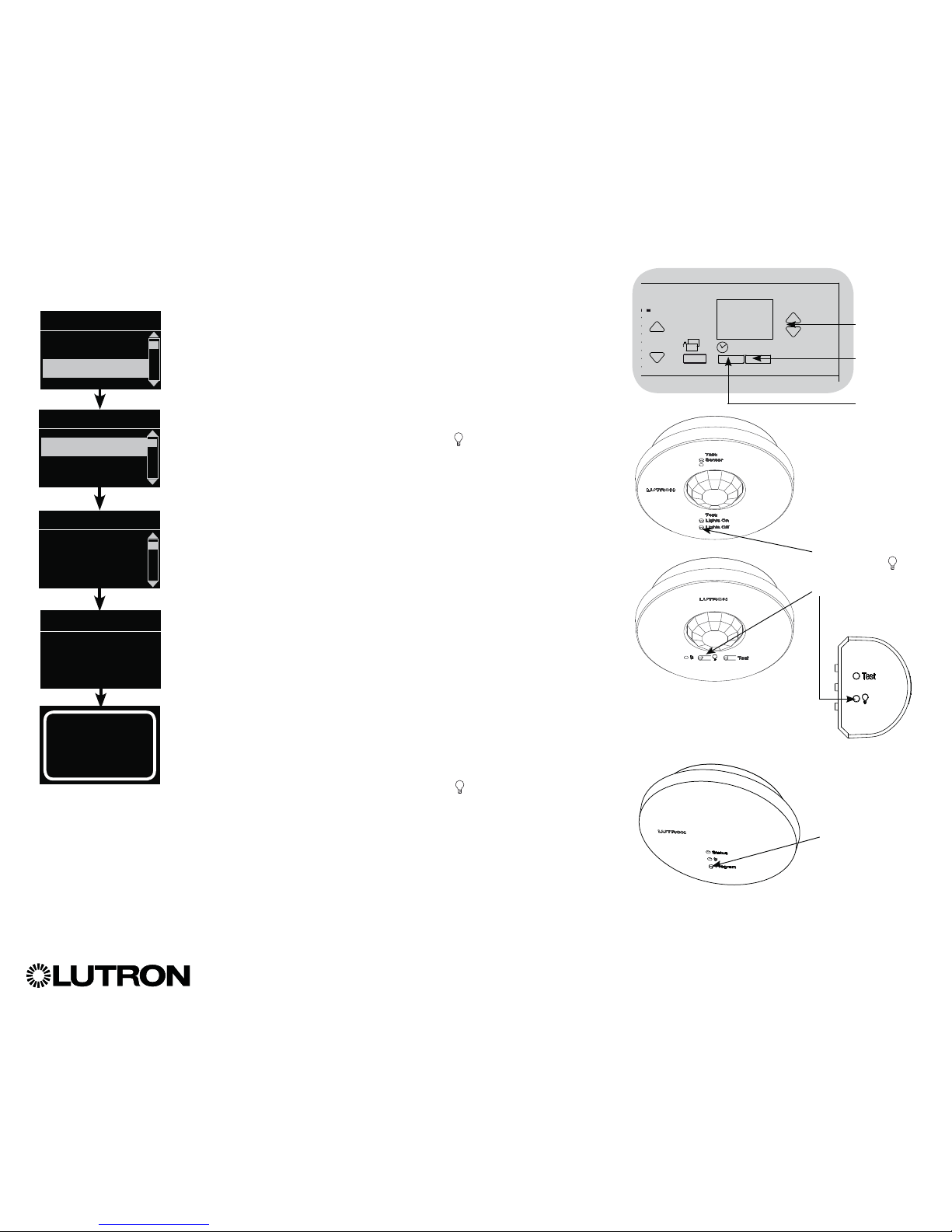
1. Make sure the wireless mode of the GRAFIK Eye® QS control
unit is “Enabled.”
2. Enter programming mode.
3. Use the Master buttons to highlight “Sensor Setup” and press
the “OK” button to accept.
4. Use the Master buttons to highlight “Add wireless sensors” and
press the “OK” button to accept.
5.
Press and hold the “Lights Off” button (
on some sensors) on
the occupancy sensor for 6 seconds. The lens will start flashing
and the info screen on the GRAFIK Eye® QS Wireless control unit
will display the sensor’s serial number.
6. Press the “OK” button on the GRAFIK Eye
® QS control unit.
A screen will confirm that the sensor has been assigned.
(To disassociate a wireless occupancy sensor from the GRAFIK
Eye® QS control unit, Refer to the Radio Powr SavrTM occupancy
sensor install guide to return the sensor to its “out-of-box”
functionality. Doing so will remove its programming from the
GRAFIK Eye® QS control unit.)
7. Repeat the above steps for all desired sensors.
8. Exit programming mode.
Associating wireless occupancy sensors through
QS Sensor Modules (QSM):
1. Press and hold the “Program” button on the QSM for 3 seconds
to enter programming mode. There will be 1 audible beep
and the Status LED will begin flashing. The info screen on the
GRAFIK Eye
® QS control unit will display that the QSM is in
programming mode.
2. Press and hold the “Lights Off” button ( on some sensors) on
the occupancy sensor for 6 seconds. There will be 3 audible
beeps from the QSM to verify association.
3. Press and hold the “Program” button on the QSM for 3 seconds
to exit programming mode.
Note: The wireless signal has a range of 30 ft (9 m) through
standard construction or 60 ft (18 m) line of sight.
Occupancy Sensor Setup (continued)
OK
16
9-16
1-8
Master
buttons
“OK”
button
Timeclock
(back) button
Main menu
Zone Setup
Sensor Setup
Occupancy
xxxx-xxxx
Press OK to Save
Add wireless sensors
Initiate association
of sensors
Saved
*Assigned*
Sensor Setup
Daylight
Add wireless sensors
“Program” button
Press and hold
“Lights Off” or
button to associate/
disassociate
QS Sensor Module (QSM)
Radio Powr Savr
TM
Occupancy Sensors
Page 27
®
GRAFIK Eye® QS Control Unit Installation and Operation Guide 27
Occupancy Sensor Setup (continued)
When the GRAFIK Eye® QS system is first powered up, occupancy sensors connected
to the contact closure input (and the first three associated wireless Radio Powr SavrTM
occupancy sensors) will automatically operate in “Scene Mode.” Their defaults will
be “No Action” for the occupied state and “Scene Off” for the unoccupied state.
For additional sensors and/or alternate functionality, please complete all required
programming actions.
Selecting the Mode
Scene Mode (default) is useful when the GRAFIK Eye
® QS control unit is controlling
lights in a single room or area. Up to 16* sensors can be assigned to the GRAFIK
Eye® QS control unit to activate a scene when the space is occupied, and another
scene when unoccupied.
Zone Mode is useful when the GRAFIK Eye
® QS control unit is controlling lights in
multiple areas within a room. Up to four sensors can be assigned to each zone
(a sensor can be assigned to more than one zone) to send the zones to configurable
occupied and unoccupied levels.
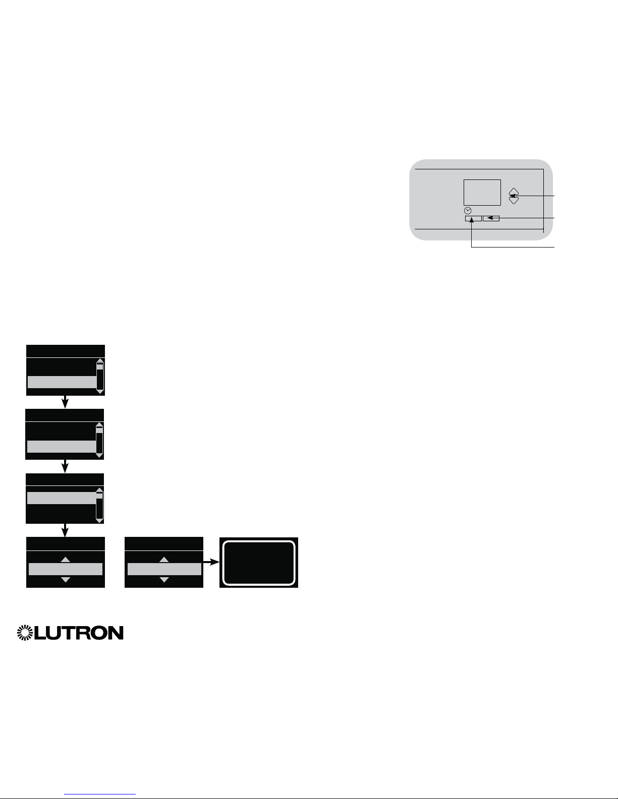
1. Enter programming mode.
2. Use the Master buttons to highlight “Sensor Setup” and press
the “OK” button to accept.
3. Use the Master buttons to highlight “Occupancy” and press the
“OK” button to accept.
4. Use the Master buttons to highlight “Mode” and press the
“OK” button to accept.
5. Use the Master buttons to highlight “Zone Mode” to assign
sensors to zones, or “Scene Mode” (default). Press the
“OK” button to accept. A screen will confirm your selected
mode has been saved and you will return to the Daylight Sensor
screen.
Note: Changing modes will remove all previous occupancy
assignments.
Main menu
Zone Setup
Sensor Setup
Occ Sensor
Scene Mode
Occ Sensor
Actions
Mode
Saved
Saved
Occ Sensor
Zone Mode
OR
OK
Master
buttons
“OK”
button
Timeclock
(back) button
Sensor Setup
Daylight
Occupancy
* Applicable only to units that ship with firmware version 9.003 and higher. Previous versions support up to 4 sensors.
Page 28

®
GRAFIK Eye® QS Control Unit Installation and Operation Guide 28
Occupancy Sensor Setup (continued)
Scene Mode
This step allows you to assign up to 16* occupancy sensors to the GRAFIK Eye® QS
control unit.
Selecting Sensors
1. If not already done, associate occupancy sensors and set to
“Scene Mode.”
2. Use the Master buttons to highlight “Setup” and press the
“OK” button to accept. The info screen will display “Searching”
while the unit detects available occupancy sensors.
3. Use the Master buttons to scroll through the list of available
occupancy sensors. When the desired sensor is displayed,
press the “OK” button to select it. Then choose “Assign” or
“Unassign” from the following menu and press OK. Once a
sensor has been assigned, it will appear with an asterisk (*)
in the sensor list. Repeat for additional sensors.
Note: If wireless sensors are not found, verify that they are
associated correctly.
Setting the Sensor Action
1. Press the Timeclock (back) button to return to the Occ Sensor
screen. Use the Master buttons to highlight “Actions” and press
the “OK” button. By default, the occupied scene is set to “No
Action” and the unoccupied scene is set to “Scene Off.”
2. Use the Master buttons to highlight the scene you wish to
use for occupied status and press the “OK” button to accept.
Repeat for the scene you wish to use for unoccupied status.
Press the “OK” button to accept.
3. Exit programming mode.
Saved
Saved
3 seconds
Occ Sensor
Setup
Actions
Occupied Scene
Scene 1
Unoccupied Scene
Scene Off
Occ Sensor
Labels
Setup
Sensor x/y
xxxxxxxx
yyyy-yyyy
RF
Sensor *x/y
xxxxxxxx
yyyy-yyyy
RF
Assignment
Unassign
Assign
Saved
*Assigned*
Saved
Searching
OK
Master
buttons
“OK”
button
Timeclock
(back) button
* Applicable only to units that ship with firmware version 9.003 and higher. Previous versions support up to 4 sensors.
Page 29
®
GRAFIK Eye® QS Control Unit Installation and Operation Guide 29
Occupancy Sensor Setup (continued)
Zone Mode
This step allows you to assign up to four occupancy sensors per zone to the GRAFIK
Eye® QS control unit. Sensors can be added to more than one zone.
Selecting Sensors
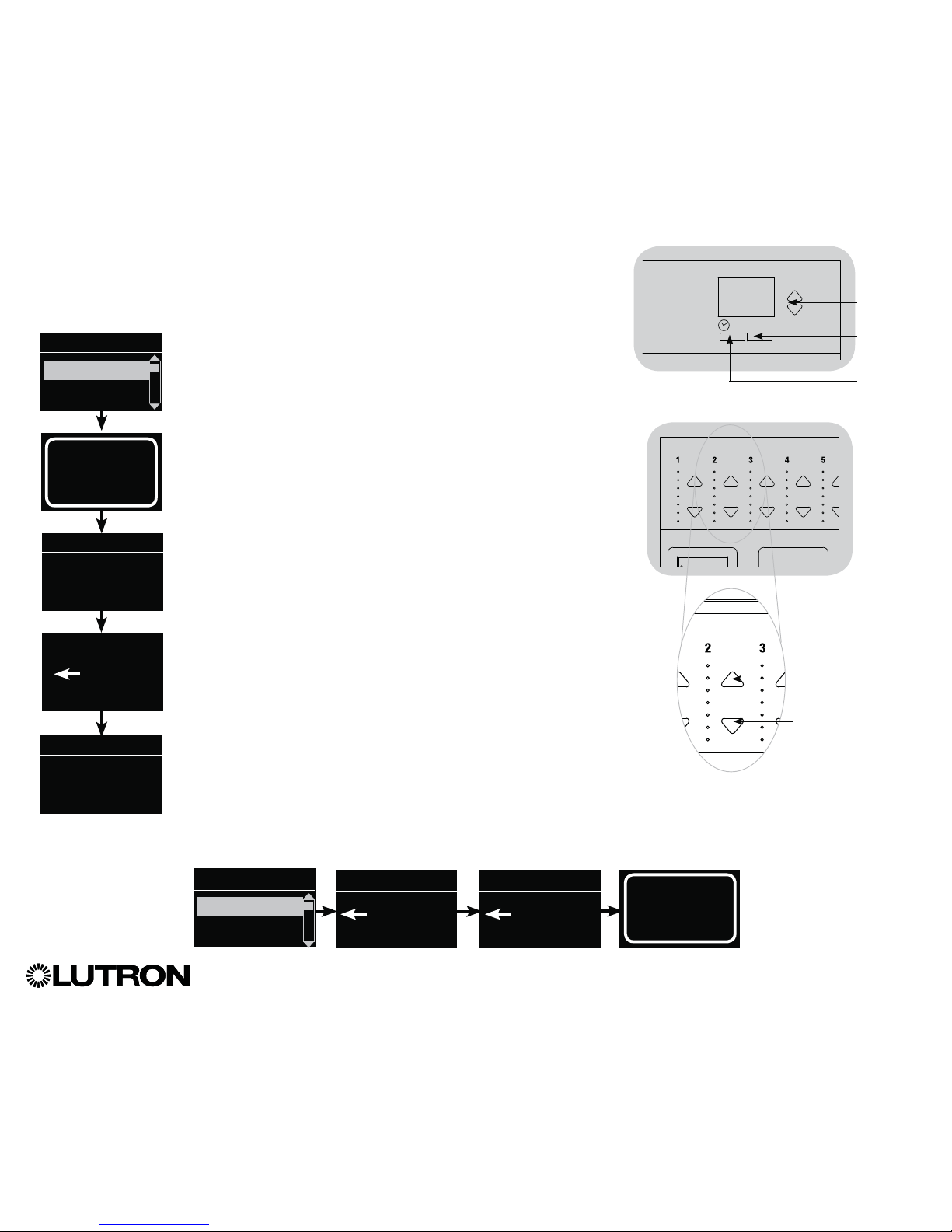
1. If not already done, associate sensors and set to “Zone Mode.”
2. Use the Master buttons to highlight “Setup” and press the
“OK” button to accept.
3. You can assign up to four sensors per zone, and a sensor can
be assigned to more than one zone. Use the Master buttons to
scroll through the sensors until the one you wish to assign or
unassign is highlighted, and press the “OK” button to select it.
4. Use the zone raise and lower buttons for each desired zone
to assign or unassign the sensor to that zone. The zone raise
button assigns the displayed sensor, and the zone lower button
unassigns it. Press the Timeclock (back) button to return to the
list of available sensors. Once a sensor has been assigned,
it will appear with an asterisk (*) in the sensor list. Repeat for
additional sensors.
Note: If wireless sensors are not found, verify that they are
associated correctly.
Setting the Sensor Action
1. Press the Timeclock (back) button to return to the Occ Sensor
screen. Use the Master buttons to highlight “Actions” and press
the “OK” button to accept.
2. Use the zone raise and lower buttons to adjust each zone to the
desired occupied level and press the “OK” button to save.
To set a zone as unaffected, lower the light levels all the way to
off, then hold the zone lower button for 3 seconds. The screen
will display “---” and the three middle LEDs for the zone will be
lit to indicate this zone is unaffected by the scene (the zone will
not change when this scene is initiated).
3. Use the zone raise and lower buttons to adjust each zone to the
desired unoccupied level, and press the “OK” button to save.
4. Exit programming mode.
Sensor
Set Zones
Occupied
Select Occupied
Level
Zone raise: Press to
assign the displayed
sensor
Zone lower: Press to
unassign the displayed
sensor
Occ Sensor
Labels
Setup
Sensor x/y
xxxxxxxx
yyyy-yyyy
RF
Unoccupied
Select Unoccupied
Level
Saved
Saved
3 seconds
Occ Sensor
Setup
Actions
Saved
Searching
OK
Master
buttons
“OK”
button
Timeclock
(back) button
Sensor *x/y
xxxxxxxx
yyyy-yyyy
RF
Page 30
®
GRAFIK Eye® QS Control Unit Installation and Operation Guide 30
Occupancy Sensor Setup (continued)
Labeling an Occupancy Sensor (optional)
1. Enter programming mode.
2. Use the Master buttons to highlight “Sensor Setup” and press
the “OK” button to accept.
3. Use the Master buttons to highlight “Occupancy” and press
the “OK” button to accept.
4. Use the Master buttons to highlight “Labels” and press the
“OK” button to accept.
5. Use the Master buttons to display an occupancy sensor to
label and press OK to select.
6. Use the Master buttons to scroll through the characters
(lowercase and uppercase letters, plus numbers 0 through 9).
The character you are currently changing will be underlined
on the screen. Press OK to select the character you want,
then repeat for all available characters. Choose a space (no
character) and press OK for any remaining characters. The
info screen will confirm that your name has been saved.
Repeat for all desired sensors.
7. Exit programming mode.
Saved
Saved
Main menu
Zone Setup
Sensor Setup
Occ Sensor
Settings
Labels
Sensor x/y
xxxxxxxx
yyyy-yyyy
RF
OK
Master
buttons
“OK”
button
Timeclock
(back) button
Label sensor x/y
1: A
A
1 / 11
Sensor Setup
Daylight
Occupancy
Page 31
®
GRAFIK Eye® QS Control Unit Installation and Operation Guide 31
Occupancy Sensor Setup (continued)
Configuring Occupancy Sensor Settings (optional)
Occupancy Sensor Settings
Note: These settings affect all sensors assigned to the
GRAFIK Eye
® QS control unit.
Grace Period: If the GRAFIK Eye
® QS control unit is
transitioning to an unoccupied state, motion detected within
the grace period will return the lights to the previously
occupied level.
Range: 0 – 30* seconds (default 15 seconds).
Vacancy Delay: An additional time delay after vacancy is
detected and before unoccupied action occurs. Use when
occupancy sensor does not provide sufficient delay.
Range: 0 – 30 minutes (default 0 minutes).
Auto Turnoff: If lights assigned to an occupancy sensor are
turned on manually without the sensor reporting occupancy,
the GRAFIK Eye
® QS control unit can be set to automatically
turn off the lights after a set time delay. Disable this feature by
setting the time delay to 0 (disabled).
Range: Disabled or 1 – 30 minutes (default Disabled).
Zone Fade: When in “Zone Mode,” lights can be set to fade to
the unoccupied levels over this period of time.
Range: 0 – 59 seconds; 1 – 10 minutes (default 10 seconds).
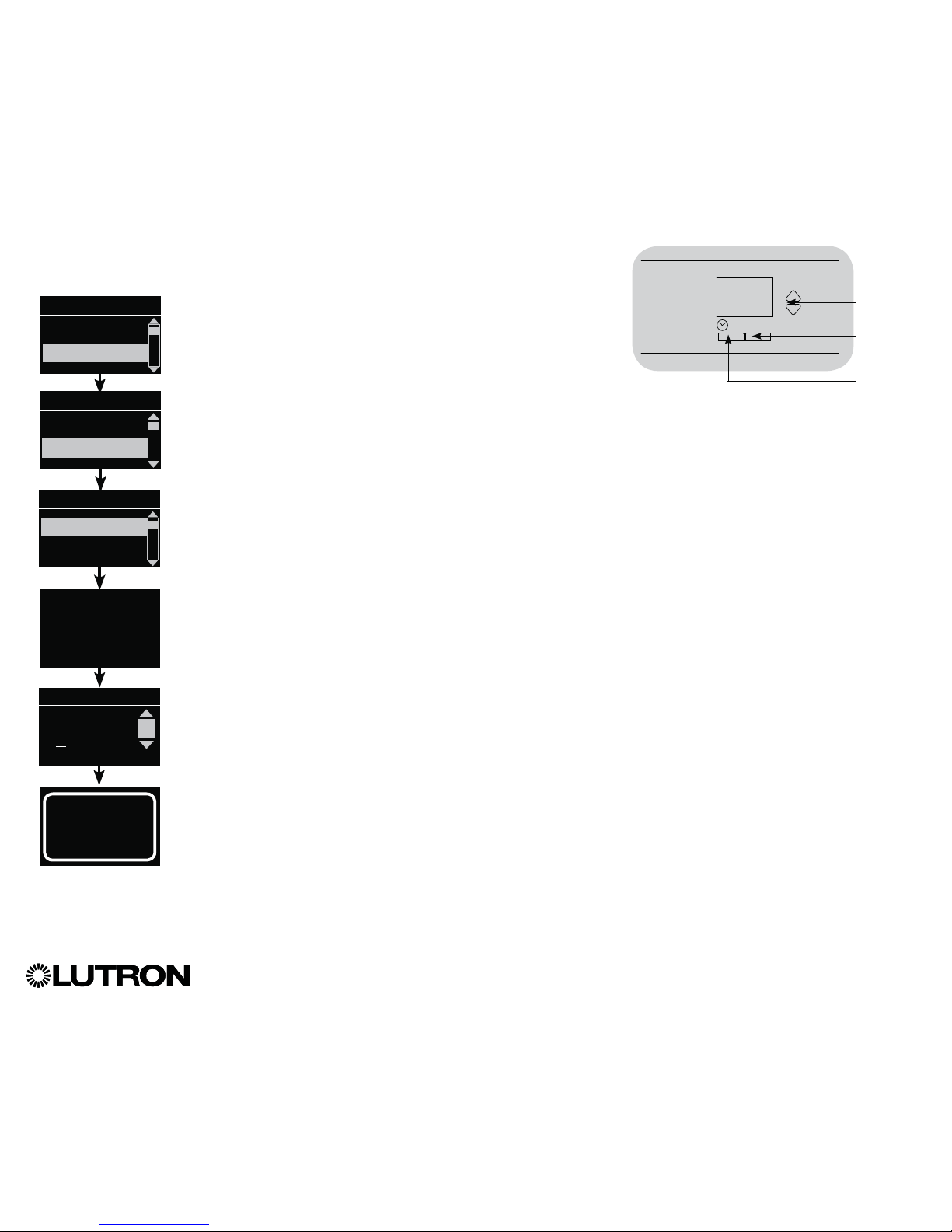
Configuring the Sensor Settings:
1. Enter programming mode.
2. Use the Master buttons to highlight “Sensor Setup” and press
the “OK” button to accept.
3. Use the Master buttons to highlight “Occupancy” and press
the “OK” button to accept.
4. Use the Master buttons to highlight “Settings” and press the
“OK” button to accept.
5. Use the Master buttons to highlight the setting you wish to
configure. Press the “OK” button to accept.
6. Use the Master buttons to adjust the value of the selected
setting. Press the “OK” button to accept.
7. The info screen will confirm that your setting has been saved.
8. Exit programming mode.
Auto Turnoff
5 minutes
Saved
Saved
Main menu
Zone Setup
Sensor Setup
Occ Sensor
Diagnostics
Settings
Settings
Zone Fade
Auto Turnoff
OK
Master
buttons
“OK”
button
Timeclock
(back) button
Sensor Setup
Daylight
Occupancy
* Applicable only to units that ship with firmware version 8.027 and higher. Previous versions support settings between 15–30 seconds.
Page 32

®
GRAFIK Eye® QS Control Unit Installation and Operation Guide 32
Lutron® daylight sensors work with the GRAFIK Eye® QS Wireless control unit to automatically adjust electric light levels when natural
light in the room changes.
Wired daylight sensors may be connected to a QS Sensor Module (QSM) in the QS system.
Wireless Radio Powr SavrTM daylight sensors can be associated with a GRAFIK Eye® QS control unit or QSM. Wireless sensors must
first be associated with one of these devices to be recognized by a GRAFIK Eye® QS wireless system.
Daylight Sensor Setup
LUTRON
LUTRON
LUTRON
LUTRON
GRAFIK Eye® QS
control unit
GRAFIK Eye
® QS
control unit
GRAFIK Eye® QS
control unit
QS
Sensor Module
(QSM)
QS
Sensor Module
(QSM)
QS Link
QS Link
Wired
Daylight
Sensor
Wireless
Daylight Sensor
Wireless
Daylight Sensor
The following steps are required to program daylight sensors with a GRAFIK Eye® QS control
unit. Instructions for each step are on the pages that follow.
1. Connect wired sensors, or associate wireless sensors.
2. Assign sensors to zones.
3. Calibrate the system to achieve the desired response to natural light.
Note: The Daylighting feature is not supported for the DMX load type.
Page 33

®
GRAFIK Eye® QS Control Unit Installation and Operation Guide 33
Associating wireless daylight sensors and GRAFIK Eye
® QS Wireless control units
(for wireless enabled units only):
1. Make sure the wireless mode of the GRAFIK Eye® QS control
unit is “Enabled.”
2. Enter programming mode.
3. Use the Master buttons to highlight “Sensor Setup” and press
the “OK” button to accept.
4. Use the Master buttons to highlight “Add wireless sensors” and
press the “OK” button to accept.
5. Press and hold the “Link” button on the daylight sensor until the
sensor starts flashing. The info screen on the GRAFIK Eye
® QS
control unit will display the sensor’s serial number.
6. Press the “OK” button on the GRAFIK Eye
® QS control unit. A
screen will confirm that the sensor has been assigned.
(To disassociate a wireless daylight sensor from the GRAFIK
Eye® QS control unit, Refer to the Radio Powr SavrTM daylight
sensor install guide to return the sensor to its “out-of-box”
functionality. Doing so will remove its programming from the
GRAFIK Eye® QS control unit.)
7. Repeat the above steps for all desired sensors.
8. Exit programming mode.
Associating wireless daylight sensors through
QS Sensor Modules (QSM):
1. Press and hold the “Program” button on the QSM for 3 seconds
to enter programming mode. There will be 1 audible beep
and the Status LED will begin flashing. The info screen on the
GRAFIK Eye
® QS control unit will display that the QSM is in
programming mode.
2. Press and hold the “Link” button on the daylight sensor for
6 seconds. There will be 3 audible beeps from the QSM to verify
association.
3. Press and hold the “Program” button on the QSM for 3 seconds
to exit programming mode.
Note: The wireless signal has a range of 30 ft (9 m) through
standard construction or 60 ft (18 m) line of sight.
Daylight Sensor Setup (continued)
OK
Master
buttons
“OK”
button
Timeclock
(back) button
Main menu
Zone Setup
Sensor Setup
Daylight
xxxx-xxxx
Press OK to Save
Add wireless sensors
Initiate association
of sensors
Saved
*Assigned*
Sensor Setup
Daylight
Add wireless sensors
“Link”
button
“Program” button
QS Sensor Module (QSM)
Radio Powr Savr
TM
Daylight Sensor
Page 34

®
GRAFIK Eye® QS Control Unit Installation and Operation Guide 34
Daylight Sensor Setup (continued)
This step allows you to assign sensors to zones on the GRAFIK Eye® QS control unit.
Each zone can be assigned to only one sensor, but sensors can be assigned to more
than one zone.
Assigning Sensors
1. If not already done, associate daylight sensors.
2. Use the Master buttons to highlight “Setup” and press the
“OK” button to accept. Available sensors will be displayed.
3. Use the Master buttons to scroll through the sensors until the
one you wish to assign or unassign is highlighted, and press the
“OK” button to select it.
4. Use the zone raise and lower buttons for the desired zones to
assign or unassign the sensor to those zones. The zone raise
button assigns the displayed sensor, and the zone lower button
unassigns it. Press the Timeclock (back) button to return to the
list of available sensors. Repeat for additional sensors.
Calibrating the Sensors
1. Put any wireless Radio Powr Savr
TM daylight sensors associated
with the desired zones into “Calibrate Mode”: Press and hold
the “Cal.” button for 6 seconds until the sensor flashes.
Note: After 5 minutes, “Calibrate Mode” will timeout, and the
sensor will return to normal mode.
2. Press the Timeclock (back) button to return to the Daylight
Sensor screen. Use the Master buttons to highlight “Calibrate”
and press the “OK” button to accept.
3. Use the Master buttons to select the desired zone and press the
“OK” button to accept.
4. Use the Master buttons to select the desired light level for the
zone, and press the “OK” button to accept. Repeat for all zone
levels you wish to calibrate.
5. Exit programming mode.
Note: If wireless sensors are not found, verify that they are
associated correctly.
Sensor
Set Zones
Zone raise: Press to
assign the displayed
sensor
Zone lower: Press to
unassign the desired
sensor
Daylight Sensor
Calibrate
Setup
Sensor x/y
xxxx-xxxx
RF
Saved
Saved
3 seconds
Daylight Sensor
Setup
Calibrate
Saved
Searching
OK
Master
buttons
“OK”
button
Timeclock
(back) button
Sensor Name
Zone 1
Adjust Light
More light
Less light
“Cal.”
button
Radio Powr Savr
TM
Daylight Sensor
Page 35

®
GRAFIK Eye® QS Control Unit Installation and Operation Guide 35
Daylight Sensor Setup (continued)
Labeling a Daylight Sensor (optional)
1. Enter programming mode.
2. Use the Master buttons to highlight “Sensor Setup” and press
the “OK” button to accept.
3. Use the Master buttons to highlight “Daylight” and press the
“OK” button to accept.
4. Use the Master buttons to highlight “Labels” and press the
“OK” button to accept.
5. Use the Master buttons to display a daylight sensor to label
and press OK to select.
6. Use the Master buttons to scroll through the characters
(lowercase and uppercase letters, plus numbers 0 through 9).
The character you are currently changing will be underlined
on the screen. Press OK to select the character you want,
then repeat for all available characters. Choose a space (no
character) and press OK for any remaining characters. The
info screen will confirm that your name has been saved.
Repeat for all desired sensors.
7. Exit programming mode.
Saved
Saved
Main menu
Zone Setup
Sensor Setup
Daylight Sensor
Diagnostics
Labels
Sensor x/y
xxxx-xxxx
RF
OK
Master
buttons
“OK”
button
Timeclock
(back) button
Label sensor x/y
1: A
A
1 / 11
Sensor Setup
Occupancy
Daylight
Page 36

®
GRAFIK Eye® QS Control Unit Installation and Operation Guide 36
LutronR Pico
® wireless controls can be associated with a GRAFIK Eye® QS system to control the light level of a specific zone or to act
as a scene controller. Pico® wireless controls can be associated directly to GRAFIK Eye® QS Wireless control units, or to a wired or
wireless GRAFIK Eye® QS control unit via a QS Sensor Module (QSM) wired on the QS link.
Pico® Wireless Control Setup
Functionality of the Pico® wireless control
Zone Function
1
Scene Function
2
Top (On) Button All assigned zones 100% Scene 1
Center (Preset) Button
(3B and 3BRL) or
second button from top
(4B-Gxx-L31)
All assigned zones at programmed preset
level
(Press and hold to save current levels on
assigned zone as preset)
Scene 2
Raise/Lower Buttons
(if available)
Vary intensity of all assigned zones Vary intensity of all zones affected by
current scene
Bottom (Off) Button All assigned zones Off Scene Off
LUTRON
LUTRON
GRAFIK Eye® QS
control unit
GRAFIK Eye
® QS
control unit
QS Sensor Module
(QSM)
QS Link
Pico® Wireless
Control
Pico
® Wireless
Control
Available Pico®
Wireless Control
Models
2-button
(2B)
3-button
(3B)
2-button
with
raise/lower
(2BRL)
3-button
with
raise/lower
(3BRL)
4-button
zone control
(4B-Gxx-L01)
4-button
scene control
(4B-Gxx-L31)
1
In zone function, user can program preset levels for assigned zones on any Pico® wireless control button. Instructions for reprogramming zone levels are provided on the next page.
2
In scene function, the starting scene of the Pico
® wireless control is selectable and zone levels in each scene can be adjusted by following the instructions in Scene Setup.
Page 37

®
GRAFIK Eye® QS Control Unit Installation and Operation Guide 37
Associating the Pico® wireless control with a GRAFIK Eye® QS Wireless control unit:
(for wireless enabled GRAFIK Eye® QS control units only)
1. Make sure the wireless mode of the GRAFIK Eye® QS control unit is
“Enabled.”
2. On the Pico® wireless control, press and hold the top (on) and bottom
(off) buttons for 3 seconds. The info screen on the GRAFIK Eye
® QS
control unit will display the Pico® wireless control options. Press the
“OK” button on the GRAFIK Eye® QS control unit to select the desired
operation type for the Pico® wireless control.
3. To assign the Pico® wireless control as a zone controller, use the
Master buttons to select “Zone” and press the “OK” button to accept.
3a. Use the zone raise/lower buttons for a zone to select a desired preset
level, and then press the zone raise and lower buttons simultaneously
for 1 second (until the zone LEDs flash at the programmed preset level).
Repeat for all zones you wish to control with the Pico
® wireless control.
3b. To program other Pico
® wireless control buttons (not including
Raise/Lower), press the desired button and repeat step 3a.
OR
4. To assign the Pico® wireless control as a scene controller, use the
Master buttons to select “Scene” and press the “OK” button to accept.
Use the Master buttons to select the desired starting scene for the
Pico® wireless control and press the “OK” button to accept. Press and
hold the top scene button on the GRAFIK Eye® QS control unit for 3
seconds (until the scene LEDs flash).
5. On the Pico
® wireless control, press and hold the top and bottom
buttons for 3 seconds until the LEDs on the GRAFIK Eye® QS control
unit stop flashing.
Note: The wireless signal has a range of 30 ft (9 m) through standard
construction or 60 ft (18 m) line of sight.
Pico® Wireless Control Setup (continued)
Zone LEDs
Zone Raise
Zone Lower
OK
Press and
hold the
top scene
button for
3 seconds
to assign
Pico
® as
a scene
controller.
Master
buttons
“OK”
button
Top/On
button
Bottom/Off
button
Pico®
Wireless
Control
Change type?
Zone
Change type?
Scene
Saved
Saved
Pico
Change type?
Press OK
OR
Button Setup
First Scene
Scenes 1–2, off
1
Page 38

®
GRAFIK Eye® QS Control Unit Installation and Operation Guide 38
Associating the Pico® wireless control through a QS Sensor Module (QSM):
(for wired or wireless enabled GRAFIK Eye® QS control units)
1. Press and hold the “Program” button on the QSM for 3 seconds
to enter programming mode. There will be 1 audible beep and
the Status LED will begin flashing. The info screen on the
GRAFIK Eye
® QS control unit will display that the QSM is in
programming mode.
2. Press and hold the bottom button on the Pico® wireless control
for 6 seconds. There will be 3 audible beeps from the QSM to
verify association.
3. Press and hold the “Program” button on the QSM for 3 seconds
to exit programming mode.
4. On the Pico® wireless control, press and hold the top (on)
and bottom (off) buttons for 3 seconds, until the LEDs on the
GRAFIK Eye® QS control unit begin to flash and the QSM
beeps 1 time. Press the “OK” button on the GRAFIK Eye® QS
control unit to select the desired operation mode for the Pico®
wireless control.
5. To assign the Pico® wireless control as a zone controller, use
the Master buttons to select “Zone” and press the “OK” button
to accept.
5a. Use the zone raise/lower buttons for a zone to select a desired
preset level, and then press the zone raise and lower buttons
simultaneously for 1 second (until the zone LEDs flash at the
programmed preset level). Repeat for all zones you wish to
control with the Pico
® wireless control.
5b. To program other Pico
® wireless control buttons (not including
Raise/Lower), press the desired button and repeat step 5a.
OR
6. To assign the Pico
® wireless control as a scene controller,
use the Master buttons to select “Scene” and press the “OK”
button to accept. Use the Master buttons to select the desired
starting scene for the Pico® wireless control and press the “OK”
button to accept. Press and hold the top scene button on the
GRAFIK Eye® QS control unit for 3 seconds (until the scene
LEDs flash).
7. On the Pico
® wireless control, press and hold the top and
bottom buttons for 3 seconds until the LEDs on the GRAFIK
Eye® control unit stop flashing and the QSM beeps 1 time.
Pico® Wireless Control Setup (continued)
“Program” button
QS Sensor Module
(QSM)
Top/On
button
Bottom/Off
button
Pico®
Wireless
Control
Change type?
Zone
Change type?
Scene
Saved
Saved
QSM
Change type?
Press OK
QSM
Programming
OR
Button Setup
First Scene
Scenes 1–2, off
1
Page 39

®
GRAFIK Eye® QS Control Unit Installation and Operation Guide 39
An infrared (IR) remote can directly control the GRAFIK Eye
® QS control unit through
the infrared receiver on the front of the GRAFIK Eye® QS control unit.
An externally powered IR repeater can also be connected to the IR terminals on
the GRAFIK Eye
® QS control unit to obtain IR remote control. This is useful for
integrating third party devices with the GRAFIK Eye® QS control unit (e.g. home theater
applications.) For a complete list of the GRAFIK Eye® QS control unit’s IR programming
commands, please see www.lutron.com/qs.
An IR remote can also indirectly control the GRAFIK Eye® QS control unit through the
QS IR Eye or a Lutron® IR receiver wired to a QS Sensor Module (QSM) to control
the light level of a specific zone or to act as a scene controller. The QS IR Eye and IR
receivers wired to the QSM must first be associated with the GRAFIK Eye® QS control
unit before they will be recognized by a GRAFIK Eye® QS system.
IR Setup
LUTRON
GRAFIK Eye® QS
control unit
IR
Remote
LUTRON
GRAFIK Eye® QS
control unit
IR
Remote
Third
Party
Device
IR Terminal
LUTRON
GRAFIK Eye® QS
control unit
QS Sensor Module
(QSM)
Wired IR
Receiver
IR
Remote
QS Link
GRAFIK Eye® QS
control unit
QS
IR Eye
IR
Remote
LUTRON
QS Link
Page 40

®
GRAFIK Eye® QS Control Unit Installation and Operation Guide 40
Enabling/disabling the IR receiver on the GRAFIK Eye
® QS control unit:
Note: These steps will also enable or disable the IR terminals on the
GRAFIK Eye® QS control unit.
1. Enter programming mode.
2. Use the Master buttons to highlight “IR Setup” and press the “OK” button
to accept
3. Use the Master buttons to highlight “Integral IR” and press the “OK” button
to accept.
4. Use the Master buttons to highlight either “Enabled” or “Disabled” and
press the “OK” button to accept. The info screen will confirm that your
settings have been saved.
5. Exit programming mode.
Saved
Saved
IR Setup (continued)
Main menu
Wireless Mode
IR menu
Timeclock
Programming
IR Setup
Integral IR
Integral IR
Enabled
OK
Master
buttons
“OK”
button
Page 41

®
GRAFIK Eye® QS Control Unit Installation and Operation Guide 41
The QS IR Eye offers advanced programmable scene control depending on the IR remote being used.
Use the chart below to select the appropriate control mode on the GRAFIK Eye
® QS control unit:
IR Remote Control Mode
GRX-IT 4 Buttons & Off or 5 Buttons
GRX-8IT 8 Buttons & Off
MIR-ITFS Favorite or Zone control
C-FLRC Favorite or Zone control
Third Party IR Remote Default
Associating the QS IR Eye with a GRAFIK Eye® QS control unit:
Note: For use with LutronR remote models GRX-IT and GRX-8IT, or with
third-party IR remotes.
1. Point the IR remote at the QS IR Eye. To enter programming mode, press and
hold the top and bottom buttons on the remote for 3 seconds until the LED on
the QS IR Eye begins to flash slowly.
2. Press and hold the top scene button on the GRAFIK Eye® QS control unit for
3 seconds. The scene LEDs will flash to confirm that the QS IR Eye has been
associated. Press the “OK” button to continue.
3. Use the Master buttons to select “Scene” and press the “OK” button to accept.
4. Use the Master buttons to select one of the scene control types (listed below)
to correspond to the IR remote that will be used with the QS IR Eye. Press the
“OK” button to accept.
If “Default” was not selected, the info screen will prompt you to select which
scene will correspond to the top button of the IR remote. Use the Master
buttons to select the desired scene, and press the “OK” button to accept. The
info screen will confirm that your settings have been saved.
Note: The “Default” scene control type will activate whichever scene command
is transmitted to the GRAFIK Eye® QS control unit.
5. Point the IR remote at the QS IR Eye. To exit programming mode, press and
hold the top and bottom buttons on the remote for 3 seconds.
Button Setup
First
Scene
1
IR Setup (continued)
Saved
Saved
OK
Press and
hold the
top scene
button for
3 seconds
to associate
QS IR Eye
Master
buttons
“OK”
button
IR Eye
Change type?
Press OK
Change type?
Scene
QS IR Eye
Change type?
Default Scene
LED
GRX-IT
GRX-8IT
Page 42
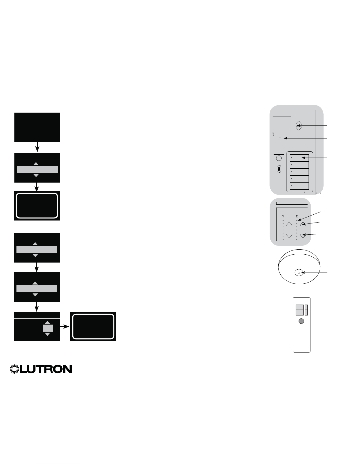
®
GRAFIK Eye® QS Control Unit Installation and Operation Guide 42
Associating the QS IR Eye with a GRAFIK Eye® QS control unit (continued):
Note: For use with Lutron® remote models MIR-ITFS and C-FLRC.
1. Point the IR remote at the QS IR Eye. To enter programming mode, press
and hold the “On” (top) button on the remote for 5 seconds, then, within
1 second, press and hold the “Off” (bottom) button on the remote for
5 seconds. The LED on the QS IR Eye will begin to flash slowly. Press
the “OK” button on the GRAFIK Eye
® QS control unit to continue.
2a. To assign the QS IR Eye as a zone controller, use the Master buttons to
select “Zone” and press the “OK” button to accept. Use the zone raise/
lower buttons on the GRAFIK Eye® QS control unit to select a desired
preset level, then press the zone raise and lower buttons simultaneously
for 1 second (until the zone LEDs flash at the programmed preset level).
Repeat for all zones you wish to assign to the QS IR Eye. The info screen
will confirm that your settings have been saved.
OR
2b. To assign the QS IR Eye as a scene controller, use the Master buttons
to select “Scene” and press the “OK” button to accept. Use the Master
buttons to select “Favorite,” and press the “OK” button to accept. Use
the Master buttons to select your desired favorite scene, and press the
“OK” button to accept. Press and hold the top scene button on the
GRAFIK Eye® QS control unit for 3 seconds (until the scene LEDs flash).
The info screen will confirm that your settings have been saved.
3. Point the IR remote at the QS IR Eye. To exit programming mode, press
and hold the “On” (top) button on the remote for 5 seconds, then, within
1 second, press and hold the “Off” (bottom) button on the remote for
5 seconds.
Button Setup
Favorite
Scene
1
IR Setup (continued)
Saved
Saved
Saved
Saved
OK
Press and
hold the
top scene
button for
3 seconds
to associate
QS IR Eye
Master
buttons
“OK”
button
IR Eye
Change type?
Press OK
Change type?
Scene
Change type?
Zone
Change type?
Favorite
QS IR Eye
LED
Zone LEDs
Zone Raise
Zone Lower
OR
MIR-ITFS
C-FLRC
Page 43
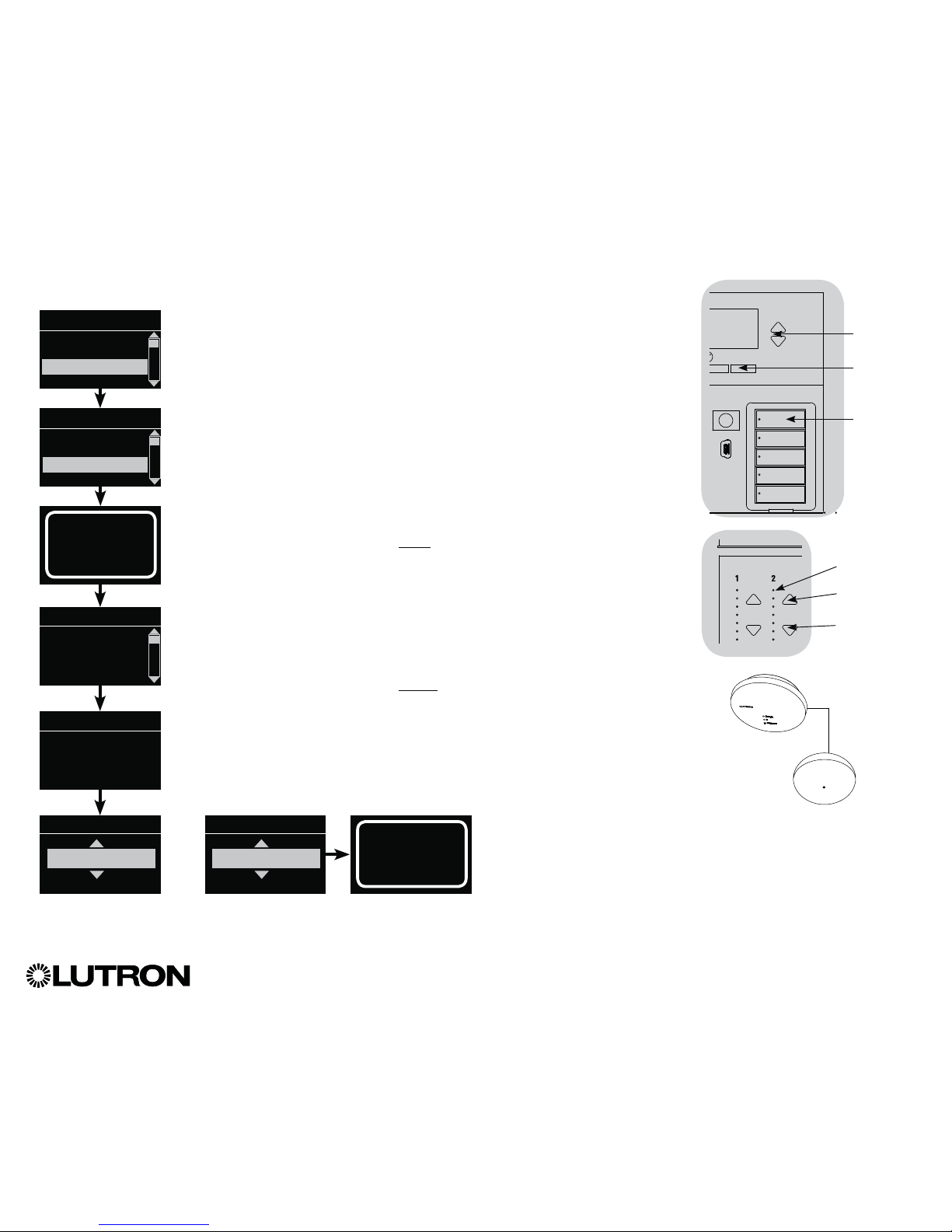
®
GRAFIK Eye® QS Control Unit Installation and Operation Guide 43
Associating IR receivers through a QS Sensor Module (QSM):
1. Upon power up, the QSM will automatically detect and
configure wired IR receivers after a valid signal is received.
Use an IR remote to send a signal to all connected receivers
in the system.
2. Enter programming mode on the GRAFIK Eye
® QS control unit.
3. Use the Master buttons to highlight “IR Setup” and press the
“OK” button to accept
4. Use the Master buttons to highlight “Programming” and
press the “OK” button to accept. The info screen will display
“Searching” while the unit detects available infrared receivers.
5. Use the Master buttons to scroll through the list of available
infrared receivers (the displayed IR receiver will flash). When the
desired IR receiver is displayed, press the “OK” button to select
it. Press the “OK” button again to continue.
6a. To assign the IR receiver as a zone controller, use the Master
buttons to select “Zone” and press the “OK” button to accept.
Use the zone raise/lower buttons for a zone to select a desired
preset level, then press the zone raise and lower buttons
simultaneously for 1 second (until the zone LEDs flash at the
programmed preset level). Repeat for all zones you wish to
control with the IR receiver.
OR
6b. To assign the IR receiver as a scene controller, use the Master
buttons to select “Scene” and press the “OK” button to accept.
Press and hold the top scene button on the GRAFIK Eye® QS
control unit for 3 seconds (until the scene LEDs flash).
7. Press the Timeclock (back) button twice to return to the list of
available IR receivers and repeat as needed.
8. Exit programming mode on the GRAFIK Eye® QS control unit.
IR Setup (continued)
Saved
Searching...
Main menu
Wireless Mode
IR menu
Integral IR
IR Setup
Programming
IR Setup x/y
xxxx-xxxx
QS 1
QSM
Change Type?
Press OK
Change type?
Zone
Change type?
Scene
Saved
Saved
Zone LEDs
Zone Raise
Zone Lower
OK
Press and
hold the
top scene
button for
3 seconds
to assign
IR receiver
as a scene
controller.
Master
buttons
“OK”
button
QS Sensor
Module (QSM)
Wired IR
Receiver
Page 44

®
GRAFIK Eye® QS Control Unit Installation and Operation Guide 44
For Sivoia® QS Shades wired directly to
the GRAFIK Eye
® QS control unit:
To associate or disassociate shades
with a shade button group:
1. On the GRAFIK Eye® QS control unit
shade button group you wish to assign
shades to, enter shade programming
mode: Press and hold the top (open) and
bottom (close) buttons simultaneously for
3 seconds. The top and bottom LEDs will
flash.
Shades that are unassigned will move to
up (open), and shades that are assigned
will move to close (down).
2. Tap the top (open) button to start
assigning.
3. Tap the top (open) button repeatedly to
cycle forward through the addresses;
tap the bottom (close) button to cycle
backward.
4. Press the shade group lower button to
associate the shade.
Press the shade group raise button to
disassociate the shade.
5. Exit shade programming mode: Press
and hold the top (open) and bottom
(close) buttons simultaneously for
3 seconds. The top and bottom LEDs
will stop flashing.
When a GRAFIK Eye
® QS system consists of Sivoia® QS shades (or drapes) and a GRAFIK Eye® QS with
one or more shade button groups, you can associate the shade button groups on the control unit with the
shades so the shade buttons can directly control the shades.
Associating Sivoia® QS Shades/Drapes and GRAFIK Eye® QS Control Units
Press and hold the top
(open) and bottom (close)
buttons on the GRAFIK
Eye® QS control unit shade
button group to enter or
exit shade programming
mode.
Open
Preset
Close
Sivoia® QS Wireless
shade/drape EDU
LED
For Wireless Sivoia® QS Shades:
To associate shades with a shade button group:
1. Make sure the wireless mode of the GRAFIK Eye
® QS control
unit is “Enabled.”
2. On the GRAFIK Eye® QS control unit shade button group you
wish to assign shades to, enter shade programming mode:
Press and hold the top (open) and bottom (close) buttons
simultaneously for 3 seconds. The top and bottom LEDs will
flash.
3. The LEDs on the electronic drive unit (EDU) and the wireless
antenna of unassociated shades/drapes will blink slowly. On
the shade/drape that you wish to associate with the shade
button group, tap any button; the LED on the EDU will blink
rapidly to indicate the shade is now associated with the
shade button group on the GRAFIK Eye® QS control unit.
4. Repeat step 2 to associate additional shades/drapes to that
shade button group.
5. Exit shade programming mode: Press and hold the top (open)
and bottom (close) buttons simultaneously for 3 seconds. The
top and bottom LEDs will stop flashing.
6. Repeat steps 1 through 5 for additional shade button groups,
as applicable.
To disassociate shades with a shade button group:
Repeat, in the same order, the steps above for associating
shades/drapes. When in shade programming mode, tap
any button on the electronic drive unit (EDU) of the shades/
drapes that you wish to disassociate from the shade button
group; the green LEDs on the EDU and antenna will blink
slowly to indicate the shade is disassociated from the shade
button group on the GRAFIK Eye® QS control unit.
Note: The wireless signal has a range of 30 ft (9 m) through
standard construction or 60 ft (18 m) line of sight.
Lower button: Press to
associate
Raise button: Press to
disassociate
Page 45
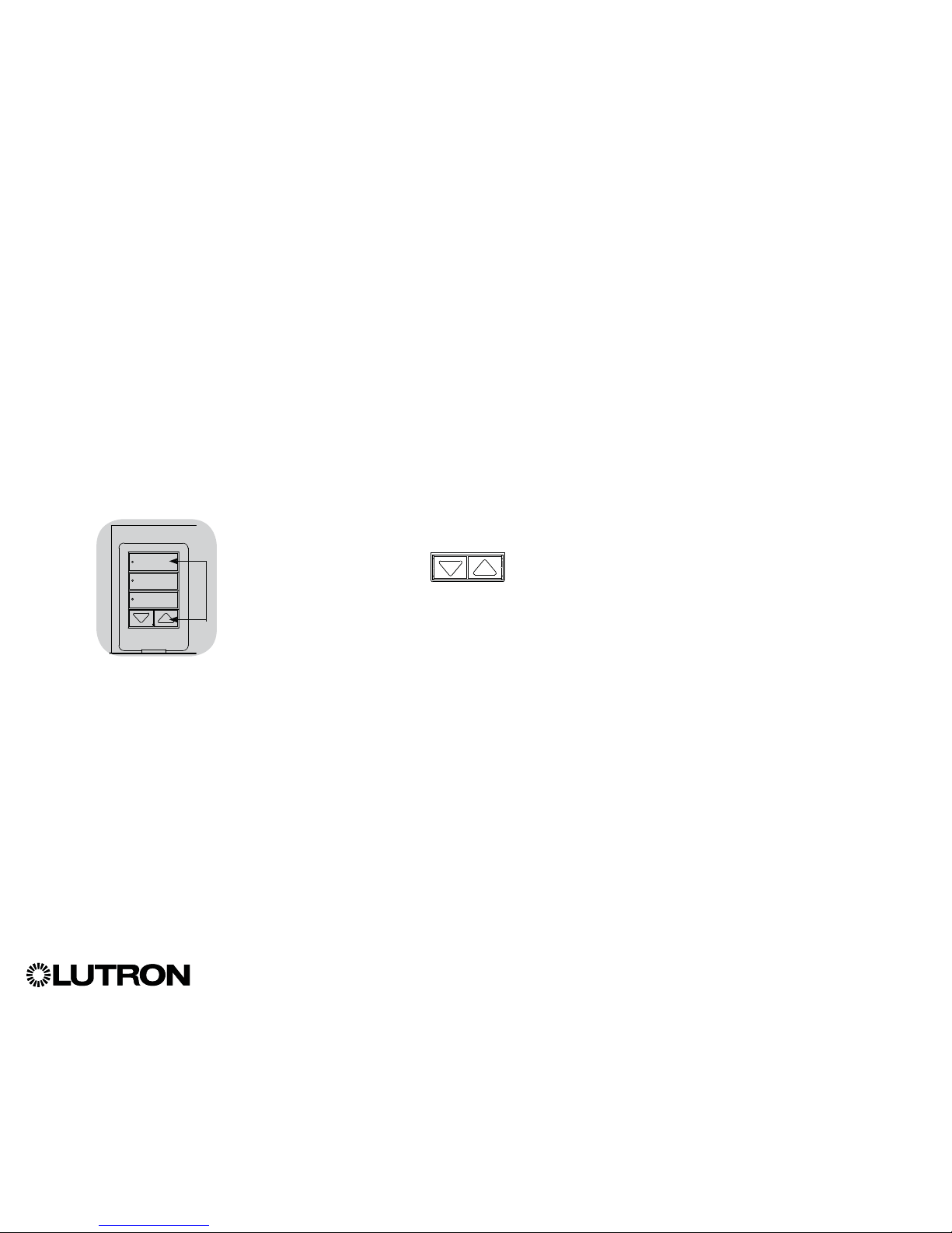
Setting Limits
(for wired shades/drapes only)
Note: Entering “Limit Setup” mode
may cause shades to move
approximately 8 in (200 mm) up or
down. Be sure that each shade
is positioned so that the fabric
can safely move 8 in (200 mm) up
or down before entering “Limit
Setup” mode.
1. On any shade button group, press and
hold simultaneously the top and raise
buttons. The LEDs next to the top and
bottom buttons will cycle.
At any time while in “Limit Setup” mode,
you can move all shades together to their
current open limit by double-tapping the
top button, or to their current close limit
by double-tapping the bottom button.
Note: Shade/drape electronic drive units
(EDUs) must first be associated to
a shade button group before its
limits can be adjusted.
2. Select the EDU you want to adjust using
the top button on the shade button
group. Each time you press and release
the top button, a different EDU that is
assigned to that shade button group will
open and close in an 8 in (200 mm) range
to indicate it is selected.
Tap the top button until the EDU for the
shade you wish to adjust moves. (You
can also use the bottom button, which
moves through the assigned EDUs in the
opposite order.)
3. Adjust the currently selected EDU to
the desired level for the open limit (the
maximum the shade is allowed to open)
using the raise and lower buttons.
4. Press and hold the top button on the
shade button group for 5 seconds to
store the current position as the open
limit. The LED next to the top button will
flash quickly for 2 seconds.
5. Adjust the currently selected EDU to
the desired level for the close limit (the
maximum the shade is allowed to close)
using the raise and lower buttons.
6. Press and hold the bottom button on
the shade button group for 5 seconds
to store the current position as the close
limit. The LED next to the bottom button
will flash quickly for 2 seconds.
7. Repeat steps 2 through 6 to set the open
and close limits for each shade assigned
to the shade button group.
8. Press and hold simultaneously the top
and raise buttons on the shade button
group to exit “Limit Setup” mode.
Note: Remote limits cannot be set for
Sivoia
® QS wireless shades through
the GRAFIK Eye® QS control unit.
Limits must be set manually at
the wireless shade EDU. (See
the Sivoia® QS wireless shade
instructions.).
®
GRAFIK Eye® QS Control Unit Installation and Operation Guide 45
Adjusting Shade Settings (for Wired and Wireless Sivoia® QS Shades/Drapes)
Page 46
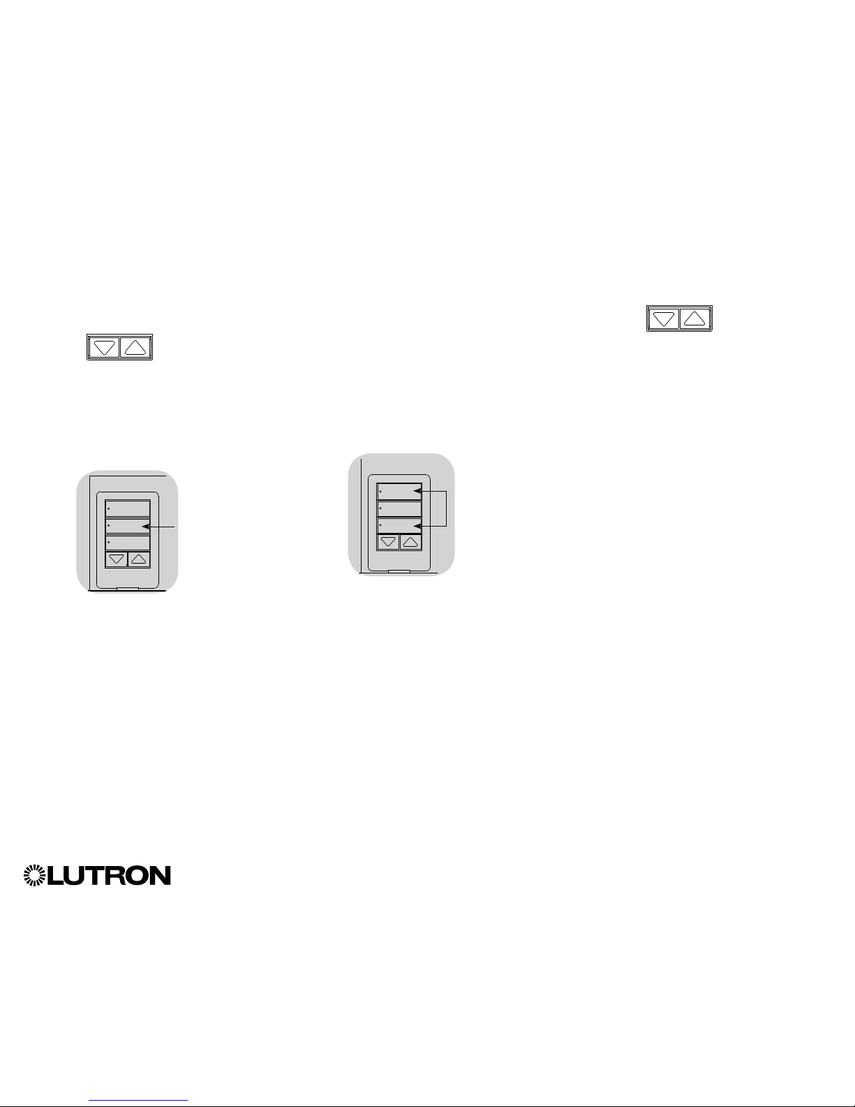
Preset Adjustment: Simple Method
1. Use the raise and lower buttons on the
shade button group to set all electronic
drive units (EDUs) of the shades to the
desired preset levels.
2. Press and hold the middle button on the
shade button group for 5 seconds to
save the EDU preset positions. The LED
next to the button will flash and then light
continuously, indicating the preset has
been stored.
Note: Once EDU presets have been
assigned to buttons on a shade
button group, those presets are
accessible for an EDU only using
the shade button group it is
assigned to, and a shade button
group can access preset levels
only for those EDUs assigned to it.
Preset Adjustment: Advanced Method
• The advanced method for adjusting
presets is needed only if you wish to
have the shades assigned to the shade
button group set at different positions in
the preset. If, however, you wish all the
shades in the group to be lined up with
one another in the preset, you should
use the Simple Method at left.
• Entering “Assignment” mode will cause
the shades to move between their open
and close limits. Verify that the open and
close limits have been set correctly.
1. On the shade button group whose
preset you wish to adjust, press and
hold simultaneously the top and bottom
buttons. The LEDs next to the buttons
will flash. EDUs for the assigned shades
will move to their closed limits, and EDUs
for unassigned shades will move to their
open limits.
2. Press and release the middle button on
that shade button group. The adjacent
LED will blink rapidly. EDUs for assigned
shades will automatically move to their
current preset settings.
3. Use the raise and lower buttons to move
all EDUs for assigned shades together to
the desired preset setting.
4. To move an EDU individually to its
desired preset setting, select the EDU
using the top button on the shade button
group. Each time you press and release
the top button, a different EDU that is
assigned to that shade button group
will open and close in an 8 in (200 mm)
range. Press repeatedly until the EDU
for the shade you wish to adjust moves.
Adjust that EDU to the desired height
using the raise and lower buttons.
Repeat this step for all assigned EDUs.
5. Once you are satisfied that all the
assigned EDUs are set to the positions
you want to assign as the preset, press
and hold the middle button on the shade
button group for 5 seconds. The preset
will be saved.
6. Press and hold simultaneously the top
and bottom buttons on the shade button
group for 5 seconds to exit to normal
mode. The LEDs next to the buttons will
stop flashing.
®
GRAFIK Eye® QS Control Unit Installation and Operation Guide 46
Adjusting Shade Settings (for Wired and Wireless Sivoia® QS Shades/Drapes) (continued)
Page 47
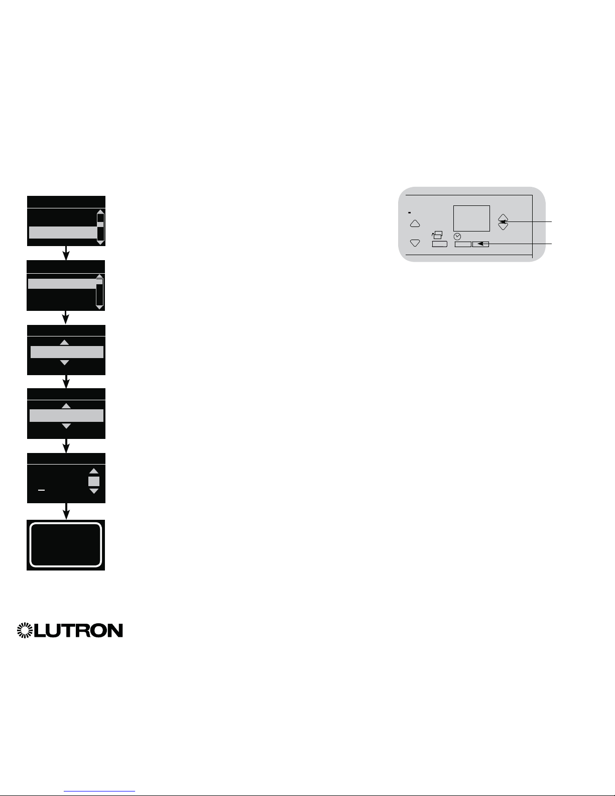
®
GRAFIK Eye® QS Control Unit Installation and Operation Guide 47
Adjusting Shade Settings (for Wired Window Treatments) (continued)
Naming a Group of Shades
1. Enter programming mode.
2. Use the Master buttons to highlight “Shade Setup” and press
the “OK” button to accept.*
3. Use the Master buttons to highlight “Shade Labels” and press
the “OK” button to accept.
4. Use the Master buttons to highlight your desired shade group.
Press the “OK” button to accept.
5. Use the Master buttons to highlight “Custom” and press the
“OK” button to accept.
6. Use the Master buttons to scroll through the characters
(lowercase and uppercase letters, plus numbers 0 through 9).
The character you are currently changing will be underlined
on the screen. Press OK to select the character you want,
then repeat for all available characters. Choose a space (no
character) and press OK for any remaining characters. Press
the “OK” button to accept.
7. The info screen will confirm that your name has been saved.
8. Exit programming mode.
Main menu
Sensor Setup
Shade Setup
Select group
Shade Grp 1
Label shade grp
Custom
Label shade grp 1
1: A
1 / 11
OK
16
9-16
1-8
A
Master
buttons
“OK”
button
Saved
* Applicable only to units that ship with firmware version 9.003 and higher. For previous versions, skip step 2 and proceed to step 3.
Shade Setup
Timeclock
Stop If Moving
Shade Labels
Page 48

®
GRAFIK Eye® QS Control Unit Installation and Operation Guide 48
Adjusting Shade Settings (for Wired Window Treatments) (continued)
Enable/Disable “Stop If Moving” Functionality (software revision 9.003 or higher)
If the GRAFIK Eye
® QS control unit can be configured to enable/disable the “Stop If
Moving” functionality: pressing shade column button stops the shade if it is already
moving, otherwise the shade is sent to the programmed level.
Follow the steps below to disable the “Stop If Moving” functionality (it is enabled by
default):
1. Enter programming mode.
2. Use the Master buttons to highlight “Shade Setup” and press
the “OK” button to accept.
3. In the Shade Setup menu, use the master buttons to highlight
“Stop If Moving” and press OK to accept.
4. For the desired shade column (on bottom left of QSG unit),
press the “Open” button to enable “Stop If Moving” for that
column or press the “Close” button to disable the “Stop If
Moving” feature. The display screen will change momentarily
to indicate if “Stop If Moving” is enabled or disabled for the
selected shade column.
5. LEDs on the “Open” and “Close” buttons will indicate the
current selection for the shade column.
6. Once the process is complete, hit the back button to go back
to the main menu.
Stop If Moving
For each shade
‘Open’ Enables
Shade Group N...
Stop If Moving
Disabled
OK
16
9-16
1-8
Master
buttons
“OK”
button
Main Menu
Timeclock
Wireless Mode
Shade Setup
Shade Labels
Stop If Moving
Shade Setup
Timeclock
(back) button
12
3
4
5
910
11 12
13
Shade
button group
Open button
Close button
Page 49

®
GRAFIK Eye® QS Control Unit Installation and Operation Guide 49
Associating Sivoia® QS Triathlon® Shades with GRAFIK Eye® QS Control Unit
Confirm Wireless Mode Enabled
1. Enter Programming mode: Press and
hold the top and bottom Scene buttons
simultaneously for 3seconds. The LEDs
in the Scene buttons will scroll from top
to bottom, confirming the control unit is
in Programming mode, and the Info
screen will display the Main menu.
2. Use the Master
buttons to highlight
“Wireless Mode” in
the Main menu, and
press the OK button
to accept.
3. Use the Master
buttons to highlight
“Enabled” and press
the OK button to
accept.
4. The Info screen will
display a confirming
“Saved” message.
5. Exit Programming
mode: Press and
hold the top and
bottom Scene buttons
simultaneously for 3seconds. The Info
screen will go to Scene 1.
Associate Shades
1. Tap the Shade button on the shade to
assign. The Shade button LED will turn on
solid green, and the shade will wait in this
mode for 30 seconds.
2. Choose a Shade button group on the
GRAFIK Eye
®QS control unit. Press and
hold the Close button in that group for
6 seconds. All LEDs in the Shade button
group and the Shade button LED will
flash then turn off.
OK
1 2 3 4 5 6
Off
1
2
3
4
GRAFIK Eye® QS Control Unit
Roller Shade Button
Honeycomb Shade Button
Main menu
Shade labels
Wireless mode
Wireless mode
Enabled
Saved
Shade button groups
Scene
buttons
Info
screen
Master
buttons
Page 50

®
GRAFIK Eye® QS Control Unit Installation and Operation Guide 50
1. Verify that the shade is associated with
the intended Shade button group of the
GRAFIK Eye
® QS control unit.
2. Tap the Shade button on the Sivoia
® QS
Triathlon
® shade. The Shade button LED
will turn on solid green, and the shade
will wait in this mode for 30seconds.
3. In the GRAFIK Eye
® QS Shade button
group associated with the shade,
simultaneously press and hold the Open
and Raise buttons for 5 seconds.
4. Use the Raise/Lower buttons to position
the shade at the desired level for the
upper limit (the maximum the shade is
allowed to open).
5. Press and hold the Open button for 5
seconds to store the current position as
the upper limit. The Open button LED will
flash quickly for 2 seconds
6. Set the lower limit: Repeat steps 2 and 3
to enter Limit Set mode.
7. Use the Raise/Lower buttons to position
the shade at the desired level for the
lower limit (the maximum the shade is
allowed to close).
8. Press and hold the Close button for
5 seconds to store the current position
as the lower limit. The Close button LED
will flash quickly for 2 seconds.
9. Repeat steps 1 through 8 to set the
upper and lower limits for each Sivoia
®
QS Triathlon® shade.
Tap shade button
OR
Setting Upper and Lower Limits of a Sivoia® QS Triathlon® Shade
with GRAFIK Eye
® QS Control Unit
Page 51

®
GRAFIK Eye® QS Control Unit Installation and Operation Guide 51
OK OK
GRAFIK Eye® QS
control unit A
“Talks” to GRAFIK
Eye® QS control unit
B; scene activation
and Master button
presses activated
on control unit A are
replicated on control
unit B.
GRAFIK Eye® QS
control unit B
“Listens” to GRAFIK
Eye® QS control
unit A; control
unit B replicates
scene activations
and Master button
presses on control
unit A.
When there is more than one GRAFIK
Eye® QS control unit in a system, it is
often convenient to associate them so
that certain functions carry over to other
associated GRAFIK Eye® QS control
units.
• Wired units: When first wired on the QS
link, all unprogrammed GRAFIK Eye
® QS
wired control units will replicate scene
activations and Master button presses by
other control units on the link. Associating
or disassociating control units determines
which units on the QS link will “talk”
or “listen” to each other. Control units
associated on a wired QS link will also
replicate timeclock and contact closure
settings.
• Wireless units: GRAFIK Eye
® QS
Wireless control units will not
automatically replicate scene activations
or Master button presses, and must
be programmed to do so. (Associating
two wireless control units will not pass
timeclock and contact closure settings
to each other.) When associating multiple
wireless control units, make sure the
wireless mode of both units is set to
“Enabled.”
Note: The wireless signal has a range
of 30 ft (9 m) through standard
construction or 60 ft (18 m) line
of sight.
To associate two GRAFIK Eye® QS
control units:
1. Begin with the GRAFIK Eye® QS control
unit that will “talk” (button presses will
be replicated on the other control unit; in
the drawing below this is GRAFIK Eye
®
QS control unit A). Press and hold the top
and bottom scene buttons until the LEDs
flash (about 3 seconds).
2. Continue with the GRAFIK Eye® QS
control unit that will “listen” (replicate
button presses on the other control unit;
in the drawing below this is GRAFIK Eye®
QS control unit B). Press and hold the top
scene button until the LEDs flash (about
3 seconds).
3. Return to the GRAFIK Eye® QS control
unit that will “talk” (A). Press and hold the
top and bottom scene buttons until the
LEDs stop flashing (about 3 seconds).
4. Repeating the process in reverse allows
GRAFIK Eye® QS control unit A to also
“listen” to GRAFIK Eye® QS control unit
B, so that both units will follow each
other.
To disassociate two GRAFIK Eye® QS
control units:
Simply repeat the association steps,
in the same order; press and hold
the bottom scene button on B to
disassociate.
Associating Multiple GRAFIK Eye® QS Control Units
OK
On the unit that will “talk,” press
and hold the top and bottom
scene buttons for 3 seconds
to begin or end association or
disassociation with the unit that
will “listen.”
OK
On the unit that will “listen,” press and hold the
top scene button for 3 seconds to associate,
or press and hold the bottom scene button for
3 seconds to disassociate with the unit that will
“talk.”
Associate
OR
Disassociate
Page 52

®
GRAFIK Eye® QS Control Unit Installation and Operation Guide 52
Timeclock Operation
Setting Time and Date
1. Enter programming mode.
2. Use the Master buttons to highlight “Timeclock” and press the
“OK” button to accept.
3. Use the Master buttons to highlight “Time & date” and press
the “OK” button to accept.
4. Use the Master buttons to highlight either “12 Hr” or “24 Hr”
format for time display and press the “OK” button to accept.
5. Use the Master buttons to highlight the current hour and press
the “OK” button to accept. Repeat for the current minutes.
6. Use the Master buttons to highlight the current year and press
the “OK” button to accept. Repeat for the current month and
date.
7. The info screen will confirm that your time and date have been
saved.
8. Exit programming mode.
OK
Master
buttons
“OK”
button
Main menu
Timeclock
Scene setup
Timeclock
End afterhours
Time & date
Set time
: 00 AM
08
Timeclock
Set date
: 00
2009
Set date
Set format
12 Hr
March
Set date
17
Set time
08 : AM
30
Saved
Page 53

Setting Daylight Saving Time
1. Enter programming mode and
select “Timeclock.” Use the Master
buttons to highlight “Set DST” and
press the “OK” button to accept.
2. Use the Master buttons to highlight
“Yes” if your location observes
daylight saving time, or “No” if it
does not. Press the “OK” button to
accept.
3. If yes, use the Master buttons to
choose either “USA 2007” (the
second Sunday in March to the first
Sunday in November), or “Other.”
For “Other,” follow the screens to
set start and end dates and amount
of time.
4. Press the “OK” button to accept.
The info screen will confirm that
your time and date have been
saved.
5. Exit programming mode.
®
GRAFIK Eye® QS Control Unit Installation and Operation Guide 53
Timeclock Operation (continued)
Setting Location
1. Enter programming mode.
2. Use the Master buttons to highlight
“Timeclock” and press the “OK” button
to accept.
3. Use the Master buttons to highlight
“Location” and press the “OK” button
to accept.
4. Use the Master buttons to set your
location by either country and city
or latitude and longitude. Press the
“OK” button to accept.
5. Use the Master buttons to highlight the
country and press the “OK” button to
accept. Repeat for the state and closest
city.
6. The info screen will confirm that your
time and date have been saved.
7. Exit programming mode.
OK
Master
buttons
“OK”
button
Main menu
Timeclock
Scene setup
Timeclock
Time & date
Location
Location by
Lat/Longitude
Country, City
Timeclock
State
Pennsylvania
City
Philadelphia
Country
08 : 00
USA
Timeclock
Location
Set DST
DST
: 00
Yes
Saved
Page 54

®
GRAFIK Eye® QS Control Unit Installation and Operation Guide 54
Timeclock Operation (continued)
Adding an Event
1. Enter programming mode.
2. Use the Master buttons to highlight “Timeclock” and press
the “OK” button to accept.
3. Use the Master buttons to highlight “Add events” and press
the “OK” button to accept.
4. Use the Master buttons to highlight the recurrence for this event: day of the week, holiday, weekdays or
weekends. Press the “OK” button to accept.
5. Use the Master buttons to highlight the location of the timeclock event (local or remote). Press the
“OK” button to accept.
• Local events affect scenes controlled by the GRAFIK Eye
® QS Control Unit
• Remote events affect scenes controlled by another device on the QS link (e.g. Energi Savr NodeTM QS)
Note: Remote timeclock events provide a virtual timeclock to devices on the QS link without a built-in
timeclock. This allows the GRAFIK Eye
® QS control unit to activate scenes on other devices without
affecting the space it controls.
6. Use the Master buttons to highlight the type of the event (fixed time of day or a relative time to sunrise or
sunset). Press the “OK” button to accept.
7. For a fixed-time event, use the Master buttons to highlight the hour for your event to begin; press the
“OK” button to accept. Repeat for the minutes.
For a relative time event, use the Master buttons and the “OK” button to set the hour, then the minutes
relative to sunrise or sunset (maximum of 1 hour, 59 minutes before or after sunrise or sunset).
8. Use the Master buttons to highlight the desired action for the timeclock event:
• Scenes 1-16, Off
• Shade Groups 1-3 open, preset, or close
• Start/End Afterhours
• Enable/Disable Occupancy
• Enable/Disable Occupied Events
• Enable/Disable Daylighting
9. The info screen will confirm that your event has been saved.
10. Repeat steps 4 through 9 for additional events.
11. Exit programming mode.
Main menu
Timeclock
Scene setup
Timeclock
Add events
Monday
Add events
Time of day
Add events
Scene
Scene 1
Set time
: 00 AM
08
Saved
Timeclock
View events
Add events
Add events
Local
OK
Master
buttons
“OK”
button
Page 55

®
GRAFIK Eye® QS Control Unit Installation and Operation Guide 55
Timeclock Operation (continued)
Deleting an Event
1. Enter programming mode.
2. Use the Master buttons to highlight
“Timeclock” and press the “OK” button
to accept.
3. Use the Master buttons to highlight
“Delete events” and press the
“OK” button to accept.
4. Use the Master buttons to highlight the
day of the week (or holiday) when the
event occurs; press the “OK” button to
accept.
5. Use the Master buttons to highlight the
event to delete; press the “OK” button to
accept.
6. A screen will appear, verifying you wish to
delete the event. Press the “OK” button
to accept and delete; otherwise, press
the Timeclock button to go back.
7. The info screen will confirm that your
event has been deleted.
8. Exit programming mode.
Main menu
Timeclock
Scene setup
Timeclock
Copy schedule
Timeclock
Delete?
Delete
8:00 AM
Scene 5
Delete
Monday
01/03
Viewing an Event
1. Enter programming mode, select
“Timeclock,” and select “View events.”
2. Use the Master buttons to highlight the
day of the week (or holiday) when the
event occurs; press the “OK” button to
accept.
3. Use the Master buttons to highlight the
event to view; press the “OK” button to
accept.
4. Press the “OK” button to return to the
Timeclock menu.
5. Exit programming mode.
Timeclock
Delete events
Add events
View events
Monday
View
8:00 AM
Scene 5
View events
Monday
1/3
L
Delete events
Deleted
OK
Master
buttons
“OK”
button
Timeclock
(back) button
Page 56

®
GRAFIK Eye® QS Control Unit Installation and Operation Guide 56
Timeclock Operation (continued)
Setting a Holiday
1. Enter programming mode.
2. Use the Master buttons to highlight
“Timeclock” and press the “OK” button
to accept.
3. Use the Master buttons to highlight
“Holiday” and press the “OK” button
to accept.
4. Use the Master buttons to highlight
“Set holiday” and press the
“OK” button to accept.
5. Use the Master buttons to highlight
the month of the holiday and press the
“OK” button to accept. Repeat for the
date.
6. The info screen will confirm that your
holiday has been set.
7. Exit programming mode.
Note: The GRAFIK Eye
® QS control
unit supports up to 25 unique
holidays. Follow the steps
in “Adding an Event” to add
Holiday timeclock events.
OK
Master
buttons
“OK”
button
Timeclock
Delete schedule
Holiday
Add event
View holiday
Set holiday
Holiday
Set holiday
1/25
1
Feb
Monday
Set holiday
1/25
Feb
14
Deleting a Holiday
1. Enter programming mode, select
“Timeclock,” select “Holiday,” and select
“Delete holiday.”
2. Use the Master buttons to highlight the
holiday you wish to delete (or delete all
holidays) and press the “OK” button to
accept.
3. Press the “OK” button to delete the
selected holiday. The info screen will
confirm that your holiday has been
deleted.
4. Exit programming mode.
Holiday
View holiday
Delete holiday
Monday
Saved
Deleted
Viewing a Holiday
1. Enter programming mode, select
“Timeclock,” select “Holiday,” and select
“View holiday.”
2. Use the Master buttons to scroll through
the dates of the programmed holidays.
3. If no holidays are programmed, the info
screen will display a screen informing
you.
4. Exit programming mode.
View Holiday
1/25
Feb 14
Monday
No Holidays
OR
Delete holiday
1/2
Feb 14
Delete holiday
1/2
Delete?
Page 57

®
GRAFIK Eye® QS Control Unit Installation and Operation Guide 57
Timeclock Operation (continued)
Copying a Schedule
1. Enter programming mode.
2. Use the Master buttons to highlight
“Timeclock” and press the “OK” button
to accept.
3. Use the Master buttons to highlight
“Copy Schedule” and press the
“OK” button to accept.
4. Use the Master buttons to highlight the
day you want to copy the schedule from
and press the “OK” button to accept.
5. Use the Master buttons to highlight the
day you want to copy the schedule to
and press the “OK” button to accept.
6. The info screen will ask you to confirm
overwriting all events occurring on the
selected day to copy to; press the “OK”
button to accept.
7. Exit programming mode.
OK
Master
buttons
“OK”
button
Timeclock
Delete schedule
Delete events
Copy schedule
Copy from
Monday
Monday
Timeclock
Overwrite
all events?
Deleting a Schedule
1. Enter programming mode, select
“Timeclock,” and select “Delete
schedule.”
2. Use the Master buttons to highlight the
day of the schedule you wish to delete
and press the “OK” button to accept.
3. The info screen will confirm that your
event has been deleted.
4. The info screen will ask you to confirm
deleting the schedule on the selected
day; press the “OK” button to accept.
5. Exit programming mode.
Timeclock
Delete events
Delete schedule
Saved
Deleted
Delete
Sunday
schedule?
Monday
Copy to
Tuesday
Monday
Delete schedule
Sunday
Page 58

®
GRAFIK Eye® QS Control Unit Installation and Operation Guide 58
Afterhours
The Afterhours feature of the GRAFIK Eye® QS control unit can be used to automatically set lights to an energy-saving level (typically
“Scene Off”). This feature allows occupants to manually turn on lights, but will automatically turn them off after a specified amount of
time.
When Afterhours starts, the lights will flash to alert occupants that the lights will soon fade to the Afterhours Scene. Occupants then
can press a keypad button to extend the time until the Afterhours feature flashes the lights again.
The Afterhours feature of the GRAFIK Eye
® QS control unit has 3 modes of operation:
• Enabled: The GRAFIK Eye
® QS control unit will allow the Afterhours feature to be activated.
• Follow: The GRAFIK Eye® QS control unit will execute the Afterhours settings of another associated device on the QS link.
• Disabled (default): The GRAFIK Eye® QS control unit will not start the Afterhours feature (even if it receives commands from a
Timeclock event, contact closure input, or another device on the QS link).
Note: The Afterhours feature must be programmed to start or end through Timeclock events, the integral contact closure input, or
another associated device on the QS link. The GRAFIK Eye® QS control unit will activate this feature only if the “Afterhours”
mode has been set to “Enabled” or “Follow.”
Afterhours Settings
Flash count: The amount of times the lights will flash to alert the room that the Afterhours Scene will soon be activated.
Range: 0 to 15 flashes (default 3 flashes)
Delay to off: The amount of time after the end of the “Flash count” before the Afterhours Scene is activated.
Range: 1 to 180 minutes (default 5 minutes)
Delay to flash: The amount of time the system will wait after the Afterhours Scene is interrupted before flashing the lights again and
restarting the Delay to off countdown.
Range: 1 to 180 minutes (default 45 minutes)
Afterhours scene: The scene that the GRAFIK Eye
® QS control unit will activate when the Delay to off expires.
Range: Scenes 1 to 16, Off (default Scene Off)
(See example on the next page.)
Page 59

®
GRAFIK Eye® QS Control Unit Installation and Operation Guide 59
Afterhours (continued)
Afterhours Examples
Afterhours starts;
Lights flash
Delay to off
Delay to off
Button press:
Office worker
Button press:
Office worker
Button press:
Security guard
Delay to off
(lights
flash)
Delay to off
(lights
flash)
Delay to off
(lights
flash)
Delay to flash
Delay to flash Delay to flash
Delay to off
Afterhours Scene
Afterhours Scene
Afterhours Scene Afterhours Scene
Example 1: Typical Office
Example 2: Late Night at Office
Example 3: Late Night/Security Check
Afterhours ends
Page 60
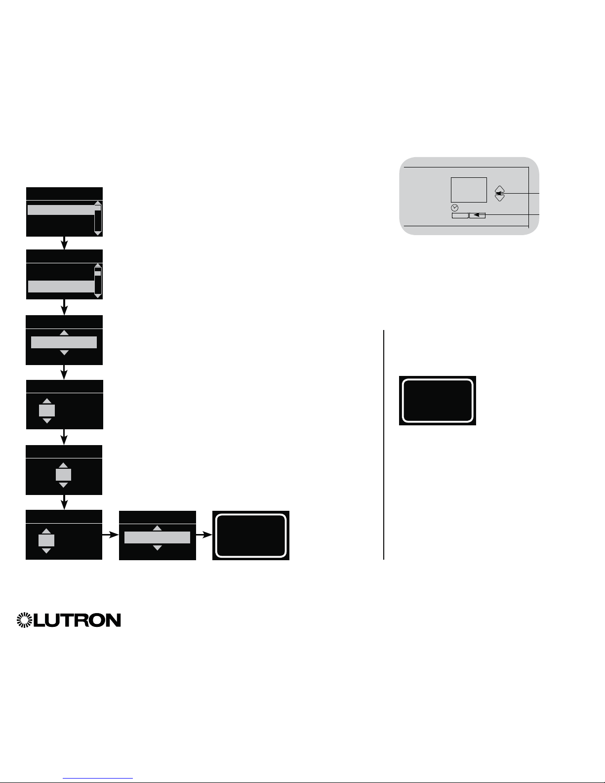
®
GRAFIK Eye® QS Control Unit Installation and Operation Guide 60
Afterhours (continued)
Setting Up Afterhours
1. Enter programming mode.
2. Use the Master buttons to highlight “Timeclock,” and press
the “OK” button to accept.
3. Use the Master buttons to highlight “Afterhours setup,” and
press the “OK” button to accept.
4. Use the Master buttons to select the desired “Afterhours”
mode, and press the “OK” button to accept.
5. (If the “Afterhours” mode was set to “Enabled”)
Use the Master buttons to highlight the desired values for
Flash count, Delay to off, Delay to flash, and Afterhours scene.
Press the “OK” button to accept each setting. The info screen
will confirm that your Afterhours settings have been saved.
6. Exit programming mode.
OK
Master
buttons
“OK”
button
Afterhours
Enabled
Flash count
3
Saved
Delay to flash
minutes
45
Delay to off
minutes
5
Afterhours
Scene off
Ending Afterhours
Once activated, the Afterhours feature can
be overridden at any time and ended through
the programming menu.
1. Enter programming
mode.
2. Use the Master
buttons to highlight
“Timeclock,” and
press the “OK” button
to accept.
3. Use the Master
buttons to highlight
“End Afterhours,” and
press the “OK” button
to accept. The info
screen will confirm
that “Afterhours” mode
is ended.
4. Exit programming
mode.
End afterhours
Main menu
Timeclock
Scene setup
Timeclock
Holiday
Afterhours setup
Timeclock
Page 61
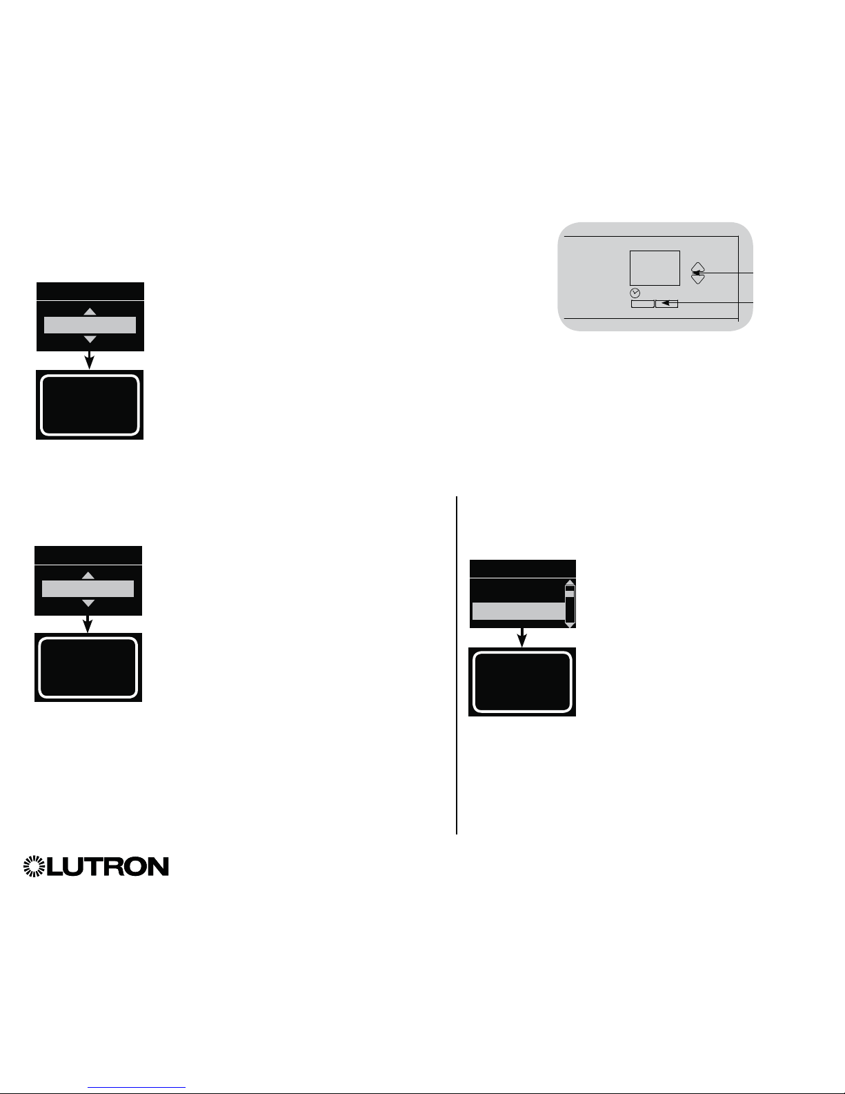
®
GRAFIK Eye® QS Control Unit Installation and Operation Guide 61
Diagnostics and Special Settings
Enabling/Disabling the Timeclock
The timeclock can be enabled or disabled as desired.
1. Enter programming mode. Use the Master
buttons to select “Timeclock.” Press the
“OK” button to accept.
2. Use the Master buttons to highlight either
“Enabled” or “Disabled.” Press the “OK”
button to accept. The info screen will
confirm that your setting has been saved.
3. Exit programming mode.
OK
Master
buttons
“OK”
button
Saved
Monday
Timeclock
Enabled
Enabling/Disabling the Backlighting
The backlighting on the info screen can be enabled or disabled as
desired.
1. Enter programming mode and select
“Backlighting.” Press the “OK” button to
accept.
2.
Use the Master buttons to highlight either
“Enabled” or “Disabled.” Press the “OK”
button to accept. The info screen will confirm
that your setting has been saved.
3. Exit programming mode.
Saved
Monday
Backlighting
Enabled
Diagnostics
If you are having trouble with your control unit and call
LutronR Technical Support, you may be asked for
diagnostic information about your unit.
1. Enter programming mode and
select “Diagnostics.” Press the
“OK” button to accept.
2. Use the Master buttons to highlight
the option that will display the
required information. The info
screen can display the device serial
number, link information, code
version, or USB status. There is
also an option to reset the USB
connection (do this only if asked to
by LutronR Technical Support).
4. Exit programming mode.
Link info
Diagnostics
Device SN
Link Info
Page 62

®
GRAFIK Eye® QS Control Unit Installation and Operation Guide 62
Diagnostics and Special Settings (continued)
Setting the Security Password
A four-digit password can be set as a security feature to protect the
programming settings on the GRAFIK Eye
® QS control unit.
1. Enter programming mode
2. Select “Diagnostics” and press the “OK” button
to accept.
3. Select “Password” and press the “OK” button
to accept.
4. Select “Set Password” and press the “OK” button
to accept.
5. You will be prompted to input a four-digit password.
Use the Master buttons to scroll through the
characters (uppercase letters and numbers 0 through
9 only). The character you are currently changing
in the password will appear underlined on the info
screen. Press OK to select the desired character,
and repeat for the remaining characters.
The info screen will confirm that your setting
has been saved.
6. Exit programming mode.
OK
Master
buttons
“OK”
button
Saved
Password
1: ABCD
4 / 4
D
Enter Password
1: * * * *
4 / 4
D
Password
Set Password
Disable
When you re-enter programming mode
after setting your password, you will be
prompted to enter your password. Use
the method in Step 5 above to select and
enter each character.
Note: The characters will appear on the
info screen as asterisks.
To disable your password, follow Steps
1 through 4 of “Setting the Security
Password,” and select “Disable” on the
Password menu.
Diagnostics
Reset USB
Password
Password
Disable
Set Password
Page 63

Language Selection
The GRAFIK Eye® QS control unit is
capable of operating in the following
languages:
• English
• French
• Spanish
• German
• Italian
• Portuguese
To change the language to one of these
choices, press the Timeclock button
four times, until the “Language” screen
is displayed. (Note: Do not put the unit
in programming mode.) Use the Master
buttons to highlight your preferred
language, and press the “OK” button to
select and save.
®
GRAFIK Eye® QS Control Unit Installation and Operation Guide 63
OK
Master
buttons
“OK”
button
Timeclock
(back) button
OK
1 2 3 4 5 6
Pull up to remove
top faceplate
Pull down to
remove bottom
faceplate
Faceplate Removal
The faceplates may need to be removed to change the color
or to write in zone labels. To remove either faceplate, open it
fully (flush to the wall), and pull up (for the top faceplate) or
down (for the bottom faceplate) to pull the hinges out of their
slots.
Replace by sliding the hinges back into their slots.
Page 64

®
GRAFIK Eye® QS Control Unit Installation and Operation Guide 64
Troubleshooting
Symptom Possible Causes Solution
Unit does not power up
Unit does not control loads
Circuit breaker is tripping
Circuit Breaker is off Switch circuit breaker on
Miswire Verify wiring to unit and loads
System short circuited Find and correct shorts
System overload Verify zone/unit loading is within ratings (see Zone Setup section)
Zone control does not work
Zone control yields incorrect
results
Miswire Make sure loads are connected to the right zones
Loose or disconnected wire Connect zone wires to loads
Burned out lamps Replace bad lamps
Incorrect load type selected Assign the zone to the appropriate load type (see Zone Setup section)
Dimming limits set incorrectly Adjust High End/Low End values (see Zone Setup section)
One or more zones are
always “full on” and zone
intensity is not adjustable
Zone control affects more
than one zone
Miswire Make sure loads are connected to the right zones
Shorted line output Check wiring; if wiring is correct, call LutronR Technical Support
Faceplate is warm Normal operation Solid-state controls dissipate about 2% of the connected load as heat. No action is required
Unit does not allow scene
change or zone adjustments
Unit is in wrong save mode Change to correct save mode
QS device in system has locked the unit Check programming and state of QS devices
Cannot program fade time
from “Scene Off”
Fade time from “Scene Off” is not
programmable; can only program fade time to
“Scene Off”
Fade time from “Scene Off” is always 3 seconds
Integral (direct-wired) contact
closure input does not work
Miswire Check wiring on contact closure input
Input CCI signal is not received Verify the input device is operating properly
Unit is in wrong CCI mode and/or type Change to correct CCI mode and/or type for your application
QS devices on link are not
working
Miswire or loose connection on QS link Verify QS link wiring to all devices
QS device is not associated Place the QS device into programming mode, and hold the “Scene 1” button on the
GRAFIK Eye
® QS control unit to associate the two devices
QS device programming is incorrect Verify the functionality and programming on the QS devices
Timeclock events do not
occur
Sunrise or sunset events do
not occur at the correct time
Timeclock is disabled Enable the timeclock
Time/date is not set correctly Set the time/date
Location is not set correctly Set the latitude and longitude of the unit’s location
Holiday schedule is in effect Normal schedule will resume when the holiday ends
Page 65

®
GRAFIK Eye® QS Control Unit Installation and Operation Guide 65
Troubleshooting (continued)
Troubleshooting: Wireless Functions
(for wireless enabled units only)
Device does not respond to
infrared controls
IR Receiver is disabled Enable the IR receiver
Miswire or loose connection on rear IR terminal Verify rear IR terminal wiring
Security lockout from
programming mode
Security password set incorrectly Call LutronR Technical Support to reset password
Symptom Possible Causes Solution
Symptom Possible Causes Solution
Cannot associate a
wireless device to a unit
Unit does not support wireless functionality Verify the unit says “GRAFIK Eye® QS Wireless” on the front label
Unit in incorrect wireless mode Change wireless mode to “Enabled”
Maximum number of devices have been
associated with unit
Remove devices or associate with a different unit
Wireless device is out of range Verify wireless device is in range: 30 ft (9 m) through standard construction, 60 ft (18 m) line of
sight
Associated wireless
devices do not control unit
Wireless device has been unassigned from unit Reassign wireless device to unit
Devices are not receiving power Check wireless device’s battery/power wiring
Unit in incorrect wireless mode Change to correct wireless mode (“Ignore Programming” or “Enabled”)
Multiple devices are associated to the unit with
contrasting settings
Verify the settings of wireless devices are consistent
Wireless device is out of range Verify wireless device is in range: 30 ft (9 m) through standard construction, 60 ft (18 m) line of
sight
Radio Powr Savr
TM daylight sensors not in
calibration mode
Follow instructions to calibrate daylight sensors
Wireless devices operate
incorrectly
Wireless devices selectively
operate
System is not configured correctly Make sure wireless device settings are programmed as desired
Intended settings were not saved Reprogram wireless device settings
Wireless devices not located correctly Follow instructions for each device to verify it is located for ideal performance
Info screen often prompts
for wireless device
association
Unit wireless mode set to “Enabled” and nearby
wireless systems are being programmed
Change wireless mode to “Ignore Programming”
Page 66

®
GRAFIK Eye® QS Control Unit Installation and Operation Guide 66
Symptom Possible Causes Solution
Shade EDU (electronic drive
unit) will not move
EDU is not powered Connect power to EDU
Shade fabric is caught on something Check and unbind shade fabric
EDU is not assigned to a shade button group Assign the EDU to a shade button group
Shade button group will not
control any shade
All limits are set to the same height Verify limit settings
Communications link is not wired to the EDU Check and wire the EDU link
EDU has been unassigned from shade button
group
Reassign the EDU to the shade button group
Shade EDU does not fully
open or fully close
Limits have been set incorrectly Set limits correctly
Shade fabric is caught on something Check and unbind shade fabric
Shade moves in the
opposite direction when
raise/lower buttons are
pushed
Open and close limits have been reversed Set limits correctly
Shade button group does
not operate all the shades it
is assigned to
EDU has been unassigned from shade button
group
Reassign the EDU to the shade button group
All limits are set to the same height Verify limit settings
EDU is not wired correctly Check and rewire EDU
Shade button group is not wired correctly Check and rewire shade button group
Shades in a room move on
their own
EDUs are assigned to a shade button group in
another room
Reassign the EDU to the correct shade button group
Unable to set limits on
Sivoia
® QS wireless shades
through the GRAFIK Eye
®
QS control unit.
Normal operation Limits must be set manually on the Sivoia
® QS wireless EDU (see Sivoia® QS wireless shade
installation guide)
Troubleshooting: Shade Functions
Page 67

®
Lutron Electronics Co., Inc.
One Year Limited Warranty
For a period of one year from the date of purchase, and subject
to the exclusions and restrictions described below, Lutron warrants
each new unit to be free from manufacturing defects. Lutron will,
at its option, either repair the defective unit or issue a credit equal
to the purchase price of the defective unit to the Customer against
the purchase price of comparable replacement part purchased
from Lutron. Replacements for the unit provided by Lutron or, at its
sole discretion, an approved vendor may be new, used, repaired,
reconditioned, and/or made by a different manufacturer.
If the unit is commissioned by Lutron or a Lutron approved third
party as part of a Lutron commissioned lighting control system, the
term of this warranty will be extended, and any credits against the
cost of replacement parts will be prorated, in accordance with the
warranty issued with the commissioned system, except that the
term of the unit’s warranty term will be measured from the date of
its commissioning.
EXCLUSIONS AND RESTRICTIONS
This Warranty does not cover, and Lutron and its suppliers are not
responsible for:
1. Damage, malfunction or inoperability diagnosed by Lutron or
a Lutron approved third party as caused by normal wear and
tear, abuse, misuse, incorrect installation, neglect, accident,
interference or environmental factors, such as (a) use of
incorrect line voltages, fuses or circuit breakers; (b) failure to
install, maintain and operate the unit pursuant to the operating
instructions provided by Lutron and the applicable provisions
of the National Electrical Code and of the Safety Standards
of Underwriter’s Laboratories; (c) use of incompatible devices
or accessories; (d) improper or insufficient ventilation; (e)
unauthorized repairs or adjustments; (f) vandalism; or (g) an act
of God, such as fire, lightning, flooding, tornado, earthquake,
hurricane or other problems beyond Lutron’s control.
2. On-site labor costs to diagnose issues with, and to remove,
repair, replace, adjust, reinstall and/or reprogram the unit or any
of its components.
3. Equipment and parts external to the unit, including those sold
or supplied by Lutron (which may be covered by a separate
warranty).
4. The cost of repairing or replacing other property that is damaged
when the unit does not work properly, even if the damage was
caused by the unit.
EXCEPT AS EXPRESSLY PROVIDED IN THIS WARRANTY,
THERE ARE NO EXPRESS OR IMPLIED WARRANTIES OF ANY
TYPE, INCLUDING ANY IMPLIED WARRANTIES OF FITNESS FOR
A PARTICULAR PURPOSE OR MERCHANTABILITY. LUTRON
DOES NOT WARRANT THAT THE UNIT WILL OPERATE WITHOUT
INTERRUPTION OR BE ERROR FREE.
NO LUTRON AGENT, EMPLOYEE OR REPRESENTATIVE HAS
ANY AUTHORITY TO BIND LUTRON TO ANY AFFIRMATION,
REPRESENTATION OR WARRANTY CONCERNING THE UNIT.
UNLESS AN AFFIRMATION, REPRESENTATION OR WARRANTY
MADE BY AN AGENT, EMPLOYEE OR REPRESENTATIVE IS
SPECIFICALLY INCLUDED HEREIN, OR IN STANDARD PRINTED
MATERIALS PROVIDED BY LUTRON, IT DOES NOT FORM A
PART OF THE BASIS OF ANY BARGAIN BETWEEN LUTRON AND
CUSTOMER AND WILL NOT IN ANY WAY BE ENFORCEABLE BY
CUSTOMER.
IN NO EVENT WILL LUTRON OR ANY OTHER PARTY BE LIABLE
FOR EXEMPLARY, CONSEQUENTIAL, INCIDENTAL OR SPECIAL
DAMAGES (INCLUDING, BUT NOT LIMITED TO, DAMAGES FOR
LOSS OF PROFITS, CONFIDENTIAL OR OTHER INFORMATION, OR
PRIVACY; BUSINESS INTERRUPTION; PERSONAL INJURY; FAILURE
TO MEET ANY DUTY, INCLUDING OF GOOD FAITH OR OF
REASONABLE CARE; NEGLIGENCE, OR ANY OTHER PECUNIARY
OR OTHER LOSS WHATSOEVER), NOR FOR ANY REPAIR WORK
UNDERTAKEN WITHOUT LUTRON’S WRITTEN CONSENT ARISING
OUT OF OR IN ANY WAY RELATED TO THE INSTALLATION,
DEINSTALLATION, USE OF OR INABILITY TO USE THE UNIT OR
OTHERWISE UNDER OR IN CONNECTION WITH ANY PROVISION
OF THIS WARRANTY, OR ANY AGREEMENT INCORPORATING
THIS WARRANTY, EVEN IN THE EVENT OF THE FAULT, TORT
(INCLUDING NEGLIGENCE), STRICT LIABILITY, BREACH OF
CONTRACT OR BREACH OF WARRANTY OF LUTRON OR ANY
SUPPLIER, AND EVEN IF LUTRON OR ANY OTHER PARTY WAS
ADVISED OF THE POSSIBILITY OF SUCH DAMAGES.
NOTWITHSTANDING ANY DAMAGES THAT CUSTOMER
MIGHT INCUR FOR ANY REASON WHATSOEVER (INCLUDING,
WITHOUT LIMITATION, ALL DIRECT DAMAGES AND ALL
DAMAGES LISTED ABOVE), THE ENTIRE LIABILITY OF LUTRON
AND OF ALL OTHER PARTIES UNDER THIS WARRANTY ON ANY
CLAIM FOR DAMAGES ARISING OUT OF OR IN CONNECTION
WITH THE MANUFACTURE, SALE, INSTALLATION, DELIVERY,
USE, REPAIR, OR REPLACEMENT OF THE UNIT, OR ANY
AGREEMENT INCORPORATING THIS WARRANTY, AND
CUSTOMER’S SOLE REMEDY FOR THE FOREGOING, WILL BE
LIMITED TO THE AMOUNT PAID TO LUTRON BY CUSTOMER
FOR THE UNIT. THE FOREGOING LIMITATIONS, EXCLUSIONS
AND DISCLAIMERS WILL APPLY TO THE MAXIMUM EXTENT
ALLOWED BY APPLICABLE LAW, EVEN IF ANY REMEDY FAILS
ITS ESSENTIAL PURPOSE.
TO MAKE A WARRANTY CLAIM
To make a warranty claim, promptly notify Lutron within the
warranty period described above by calling the Lutron Technical
Support Center at (800) 523-9466. Lutron, in its sole discretion, will
determine what action, if any, is required under this warranty. To
better enable Lutron to address a warranty claim, have the unit’s serial
and model numbers available when making the call. If Lutron, in its
sole discretion, determines that an on-site visit or other remedial action
is necessary, Lutron may send a Lutron Services Co. representative
or coordinate the dispatch of a representative from a Lutron approved
vendor to Customer’s site, and/or coordinate a warranty service call
between Customer and a Lutron approved vendor.
This warranty gives you specific legal rights, and you may also
have other rights which vary from state to state. Some states do
not allow limitations on how long an implied warranty lasts, so the
above limitation may not apply to you. Some states do not allow
the exclusion or limitation of incidental or consequential damages,
so the above limitation or exclusion may not apply to you.
NEC is a registered trademark of the National Fire Protection
Association, Quincy, Massachusetts.
Advance Mark X is a registered trademark of the Advance
Transformer Company.
Lutron,
, Sivoia, Hi-lume, Eco-10, Tu-Wire, RadioRA, Pico,
seeTouch, Triathlon, and GRAFIK Eye are registered trademarks and Radio
Powr Savr, RadioRA 2 and Energi Savr Node are trademarks of
Lutron Electron
ics Co., Inc.
© 2015 Lutron Electronics Co., Inc.
Internet: www.lutron.com
E-mail: product@lutron.com
WORLD HEADQUARTERS
USA
Lutron Electronics Co., Inc.
7200 Suter Road, Coopersburg, PA 18036-1299
TEL +1.610.282.3800
FAX +1.610.282.1243
Toll-Free 1.888.LUTRON1
Technical Support 1.800.523.9466
North and South America Technical Hotlines
USA, Canada, Caribbean: 1.800.523.9466
Mexico: +1.888.235.2910
Central/South America: +1.610.282.6701
EUROPEAN HEADQUARTERS
United Kingdom
Lutron EA Ltd.
6 Sovereign Close, London, E1W 3JF United Kingdom
TEL +44.(0)20.7702.0657
FAX +44.(0)20.7480.6899
FREEPHONE (UK) 0800.282.107
Technical support +44.(0)20.7680.4481
ASIAN HEADQUARTERS
Singapore
Lutron GL Ltd.
15 Hoe Chiang Road, Tower 15, Euro Asia Centre,
Singapore 089316
TEL +65.6220.4666
FAX +65.6220.4333
Asia Technical Hotlines
Northern China: 10.800.712.1536
Southern China: 10.800.120.1536
Hong Kong: 800.901.849
Indonesia: 001.803.011.3994
Japan: +81.3.5575.8411
Macau: 0800.401
Singapore: 800.120.4491
Taiwan: 00.801.137.737
Thailand: 001.800.120.665853
Other countries: +65.6220.4666
Warranty
Lutron Electronics Co., Inc.
P/N 032305 Rev. D 02/2015
Contact Information
 Loading...