


Lutron is a registered trademark and microOS is a
trademark of Lutron Electronics Co., Inc.
© 1997 Lutron Electronics Co., Inc.
The Lutron Power Pack (Diagram 1) is for
use with Lutron microOS Ceiling Mounted
Occupant Sensor and Lutron 0-10 Volt
Ballast Controls. The Power Pack
combines a Class 2, 15VDC power
supply and a heavy duty Form A relay.
Diagram 1: PP-20
Power Pack
Overview
Power Pack
Installation Instructions
For use with microOS™ Ceiling
Mounted Occupant Sensor and
0-10 Volt Ballast Controls
Diagram 2: Mounting
Arrangement
for Power Pack
Nut
Power
Wires
Junction
Box
Power
Pack
Class 2
Check the Application
Model: PP-20
Operating Voltage:
120 or 277VAC
The Power Pack can be used on either
120 or 277 VAC circuits. Do not exceed
the following power ratings:
16A Lutron Ballast @ 120VAC
16A Lutron Ballast @ 277VAC
For Applications with Lutron microOS
Occupant Sensors
A single Power Pack can power up to five
Lutron microOS Occupant Sensors
(MOS-CM-15-WH). As many as ten
Power Packs can be connected to one
occupant sensor for switching multiple
circuits.
For Applications with Lutron 0-10 Volt
Ballast Controls
One 0-10 Volt Ballast Control can
operate up to three Power Packs.
However, one Power Pack can not be
used with more than one 0-10 Volt
Ballast Control.
The 0-10 Volt wiring for this unit should
not exceed 500 feet with No. 20 AWG
wire. Note: For long 0-10 Volt wiring
runs, or where excessive electrical noise
exists, shielded cable or conduit is
required.
Mounting Instructions
The Power Pack is designed to be
mounted in a 1/2-inch knockout of a
standard junction box (supplied by
others) as shown in Diagram 2. The line
voltage connections to the power wires
are made inside the junction box. The
Class 2 wire connections must be made
outside the junction box.
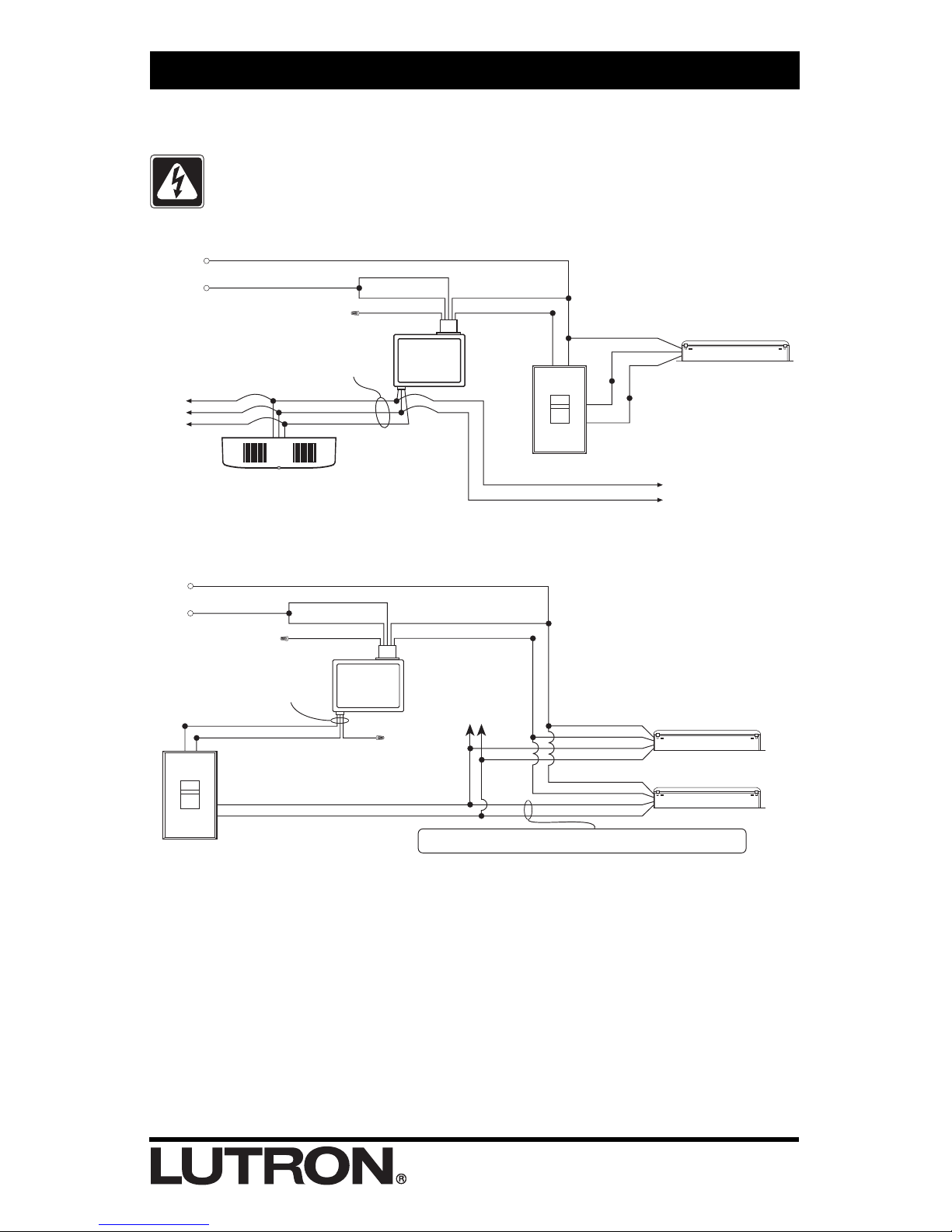
Wiring Power Pack
Wiring the Power Pack depends on the application and the line voltage. Refer
to the appropriate wiring diagram below.
Turn Power OFF Before Wiring. Do Not Wire Hot.
Danger: Locate and lock the supply breaker in the OFF position, or
remove the supply fuse before proceeding.
Lutron Electronics Co., Inc.
7200 Suter Road
Coopersburg, PA 18036-1299 U.S.A.
Made and printed in U.S.A. 11/97 P/N 031-193 Rev. A
Warranty
Lutron will, at its option, repair or replace any unit that is
defective in materials or manufacture within three years after
purchase. For warranty service, return unit to place of purchase
or mail to LUTRON at 7200 Suter Road, Coopersburg, PA
18036-1299, U.S.A., postage prepaid.
This warranty is in lieu of all other warranties, express or
implied, and the implied warranty of merchantability is
limited to three years from purchase. This warranty does not
cover the cost of installation, removal, or reinstallation, or
damage resulting from misuse, abuse, or damage resulting
from improper wiring or installation.
This warranty gives you specific legal rights, and you may also
have other rights which vary from state to state. Some states do
not allow the exclusion or limitation of incidental or consequential
damages or limitations on how long an implied warranty may
last, so the above limitations may not apply to you.
(Common)
(Signal)
(15VDC)
Red
Blue
Black
Occupant Sensor
Blue
Orange (277V)
*
Black (120V )
*
Blue
Class 2 Wiring
(No. 20 AWG)
*
When wiring for 120 volt cap off the orange wire as shown.
When wiring for 277 volt cap off the black wire and connect
the blue and orange wires to Hot.
White
Hot
Neutral
Power Pack
PP-20
To Additional
Occupant Sensors
(5 total max.)
Black White
Lutron Dimming Ballast
White
Black
Orange
Red
Yellow
To Additional Power Packs:
Cap off the red wire on all
additional Power Packs
Line Voltage
Wall Control
Diagram 3: Wiring With Occupant Sensor
Diagram 4: Wiring With 0-10 Volt Ballast Control
Black (Switched Hot)
White
Purple
Gray
Black (Switched Hot)
White
Purple
Gray
Gray
Purple
Blue
Red
Blue
To Additional Ballast
s
(Total of 60 Ballasts max.)
0-10 Volt
Wall Control
Blue
Orange (277V)
*
Black
Black (120V )
*
Blue
Class 2 Wiring
(No. 20 AWG)
0-10 Volt Dimming Ballast
Red
White
Hot
Power Pack
PP-20
Neutral
0-10V CONTROL SIGNAL WIRES—DO NOT CONNECT TO LINE VOLTAGE
Lutron is not liable for damage due to miswiring
0-10 Volt Dimming Ballast
*
When wiring for 120 volt cap off the orange
wire as shown.
When wiring for 277 volt cap off the black
wire and connect the blue and orange wires
to Hot.
Worldwide Technical and
Sales Assistance
If you need assistance call the
toll-free
Lutron Technical
Assistance Hotline.
Please provide
exact model number when calling.
(800) 523-9466 (U.S.A., Canada,
and the Caribbean)
other areas, call (610) 282-3800
Fax (610) 282-3090
 Loading...