

Page 1
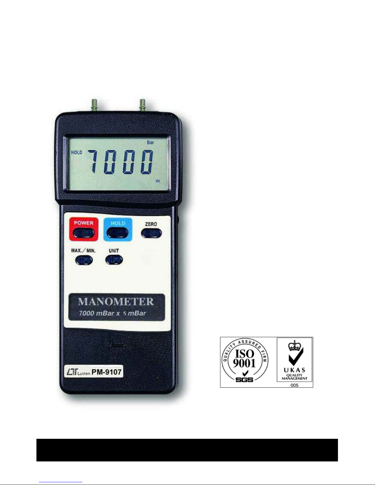
7000 mbar, differential input
MANOMETER
Model : PM-9107
Your purchase of this
MANOMETER marks a step
forward for you into the
field of precision
measurement. Althou
g
h
this MANOMETER is a
complex and delicate
instrument, its durable
structure will allow many
years of use if proper
operatin
g
techniques are
developed. Please read
the followin
g
instructions
carefully and always keep
this manual within easy
reach.
OPERATION MANUAL
Page 2

TABLE OF CONTENTS
1. FEATURES............................................................... 1
2. SPECIFICATIONS..................................................... 1
2-1 General Specifications........................................
.
1
2-2 Electrical Specifications....................................... 3
3. FRONT PANEL DESCRIPTION.................................... 4
3-1 Display............................................................ 4
3-2 Power Off/On Button........................................ 4
3-3 Hold Button..................................................... 4
3-4 Zero Button.................................................. 4
3-5 " MAX./MIN. " Button.......................................
.
4
3-6 Unit Button............... 4
3-7 P1 input socket................................................ 4
3-8 P2 input socket................................................ 4
3-9 RS-232 Output Terminal................................... 4
3-10 Battery Compartment/Cover..............................4
3-11 PLu
g
/quick coupler........................................... 4
4. MEASURING PROCEDURE......................................... 5
5. AUTO POWER OFF DISABLE.....................................
.
6
6. RS232 PC SERIAL INTERFACE................................... 7
7. BATTERY REPLACEMENT.......................................... 8
Page 3

1. FEATURES
* Dual & differential input, 7000 mbar ( 7 bar ) max. range.
* Application : Industrial, laboratory, heating,
ventilation, medical hospital, used for air or not
corrosive and not ionized gas & liquid.
* Sensor is built inside the housing.
* Single lugs for pipe connection.
* 8 kind display units ( mbar, psi, Kg/cm 2 mm Hg,
inch Hg, meter HF2 , inch HF2 , Atmosphere ) select
by push button on the front panel
* Auto shut off saves battery life.
* Zero button on the front panel, easy to offset the
zero value.
* Microprocessor circuit assures maximum possible
accuracy, provides special functions and features,
* Super large LCD display with contrast adjustment
for best viewing angle.
* Records maximum & minimum readings with recall.
* Data Hold function for stored the desired value on
display.
* Built-in low battery indicator.
* RS232 PC serial interface, can match the personal
computer used as the Data Logger, Recorder.... &
other modern pressure measuring system.
2. SPEC
IFICATION
S
2-1 General Specifications
Circuit Microprocessor LSI circuit.
Display 61 mm x 34 mm supper large LCD
display. 15 mm ( 0.6" ) digit size.
1
Page 4

Display units mbar, psi, Kg/cm 2 mm Hg, inch Hg,
meter HF2 , inch HF2 , Atmosphere.
Function Dual & differential input, data hold,
zero/relative, memory.
Zero adjust Push button on the front panel.
Sensor * Sensor is built inside the housing.
* Piezoelectric sensor.
* Used for dry, non-corrosive and
non-ionic air and gas only.
Liquid is prohibited.
Data hold By push button.
Data record Record maximum & minimum readings.
Data output RS 232 PC serial interfa ce.
Sampling time Approx. 0.8 second.
Power off Auto shut off, saves battery life or manual off
by push button.
Operating 0 to 50 蚓 ( 32 to 122 蚌 ).
temperature
Operating Less than 80% R.H.
humidity
Power supply 006P DC 9V battery ( heavy duty ).
Power current Approx. DC 6.0 mA.
Weight 345 g/0.76 LB .
Dimension 180 x 72 x 32 mm ( 7.1 x 2.8 x 1.3 inch ).
Accessories * Instruction manual....................... 1 PC.
included * Hard carrying case....................... 1 PC.
* PLug for quick coupler.................. 2 PCs.
Optional * Data acquisition software
accessories ( Windows version )........SW-U101-WIN
* RS232 cable.................. UPCB-01
2
Page 5

2-2 Electrical Specifications
Unit Max. range Resolution
mbar 7000 mbar 5 mbar
psi 101.5 psi 0.05/0.1 psi *
Kg/cm 2 7.135 Kg/cm 2 0.005 Kg/cm 2
mm Hg 5250 mm Hg 5 mm Hg
inch Hg 206.7 inch Hg 0.1 inch Hg
meter HF2 71.35 meter HF2 0.05 meter HF2
inch HF2 2810 inch HF2 2 inch HF2
Atmosphere 6.905 Atmosphere 0.005 Atmosphere
* psi resolution : Less than 100 psi is 0.05 psi, others is 0.1 psi.
Unit Max. range Accuracy
mbar 7000 mbar 2 % F. S.
psi 101.5 psi
Kg/cm 2 7.135 Kg/cm 2
Note :
mm Hg 5250 mm Hg
* 23 5 蚓.
inch Hg 206.7 inch Hg
* F.S. : full scale
meter HF2 71.35 meter HF2
* Included linearity,
inch HF2 2810 inch HF2
hysteresis and
Atmosphere 6.905 Atmosphere
repeatability
Remark
:
Measuring unit Display unit
mbar m Bar
psi Psi
Kg/cm 2 Kg /cm 2
mm Hg mm /Hg
inch Hg in/Hg
meter HF2 m HF2
inch HF2 inch HF2
Atmosphere ATP
3
Page 6

3. FRONT PANEL DESCRIPTION
Fig. 1
3-1 Display 3-7 P1 input socket
3-2 Power Off/On Button 3-8 P2 input socket
3-3 Hold Button 3-9 RS-232 Output
3-4 Zero Button Terminal
3-5 " MAX./MIN. " Button 3-10 Battery Compartment
3-6 Unit Button /Cover
3-11 PLug/ quick coupler
4
Page 7

4. MEASURING PROCEDURE
1)Power on the meter by pressing the " Power Off/On
Button " ( 3-2, Fig. 1 ).
2)Select the desired temperature units ( mbar, psi, Kg/cm 2
mm Hg, inch Hg, meter HF2 , inch HF2 , Atmosphere )
by pushing the " Unit Button " ( 3-6, Fig. 1 ).
3)Zero adjusting
Adjust the display reading to zero value by pushing
the " Zero Button " ( 3-4, Fig. 1 )
4)Install the measuring pipe to " Plug/quick coupler "
( 3-11, Fig. 1 ).
5)The meter is build the two input socket ( P1 input socket,
P2 input socket) for accepting the differential pressure
input.
Connecting the pipe along the " Plug " ( 3-11, Fig. 1) to
a.
" P1 input socket " ( 3-7, Fig. 1 ) only
b.
" P2 input socket " ( 3-8, Fig. 1 ) only
c.
Both P1 & P2 input socket
The LCD will show the measuring pressure value.
Note :
*
If the P1 pressure > P2 pressure, the display will
get positive reading.
*
If the P1 pressure < P2 pressure, the display will
get negative reading.
6)Data Hold
* During the measurement, pressing the " Hold Button "
( 3-3, Fig. 1 ) will freeze the measured value & the LCD
will show " HOLD " symbol.
* Press the " Hold Button " again to cancel the data hold
function.
5
Page 8

7)Data Record ( Maximum, Minimum reading )
* The DATA RECORD function displays the maximum
and minimum readings. To start the DATA RECORD
function, press the " MAX./MIN. Button " ( 3-5, Fig. 1 )
once. " REC " symbol will appear on the LCD display.
* With the " REC " symbol on the display :
(a) Press the " MAX./MIN. Button " ( 3-5, Fig. 1 )
once, the " Max " symbol along with the maximum
value will appear on the display.
(b) Press the " MAX./MIN. Button " again, the " Min "
symbol along with the minimum value will appear
on the display.
(c) To exit the memory record function, press the
" MAX./MIN. Button " continuously for at least 2
seconds. The display will revert to the current reading.
8)For quick measurement, follow the procedures
shown below :
Main procedures :
POWER
ZERO ADJUST
ON
DETERMINE UNIT
Optional measuring procedures :
DATA HOLD MEMORY RECORD RS232 OUTPUT
Max., Min.
Power managemen
t
AUTO POWER OFF or MANUAL POWER OFF
(Not activated during
Memory Record Selection)
6
Page 9

5. AUTO POWER OFF DISABLE
The instrument has built-in " Auto Power Shut-off " in
order to prolong battery life. The meter will switch off
automatically if none of the buttons are pressed within 10
min.
To de-activate this feature, Select the memory record
function during measurement, by pressing the " MAX./MIN.
Button " ( 3-5, Fig. 1 ).
6. RS232 PC SERIAL INTERFACE
The instrument features an RS232 output via 3.5 mm
Terminal ( 3-9, Fig. 1 ).
The connector output is a 16 digit data stream which
can be utilized to the user's specific application.
An RS232 lead with the following connection will
be required to link the instrument with the PC
serial input.
Meter PC
(3.5 mm jack plug) (9W 'D" Connector)
Center Pin..................................Pin 2
Ground/shield............................... Pin 5
7
Page 10

The 16 digit data stream will be displayed in the
following format :
D15 D14 D13 D12 D11 D10 D9 D8 D7 D6 D5 D4 D3 D2 D1 D0
Each digit indicate the foll o wi n g sta tu s :
D0 End Word
D1 to D8 Display reading, D1=LSD, D8=MSD
For example : If the display reading is 1234, the
n
D8 to D1 is 0000123
4
D9 Decimal Point ( DP ) for Upper display.
0 = No DP, 1= 1 DP, 2 = 2 DP, 3 = 3 DP
D10 Polarity 0 = Positive 1 = Negative
D11 & D12 Annunciator for Upper Display
mbar = 86 psi = 23
mm Hg = 78 inch Hg = 80
inch HF2 = 25 Kg/cm 2= 77
Atmosphere = 26 meter HF2 = 79
D13 1
D14 4
D15 Start Word
7. BATTERY REPLACEMENT
1)When the left corner of LCD display show " LBT ",
it is necessary to replace the battery. However,
in-spec measurement may still be made for several
hours after low battery indicator appears before the
instrument become inaccurate.
2)S lide the Battery Cover ( 3-10, Fig. 1) away from the
instrument and remove the battery.
3)Install a 9 V battery (PP3 type) and replace the cover.
8
0101-PM-9107
 Loading...