

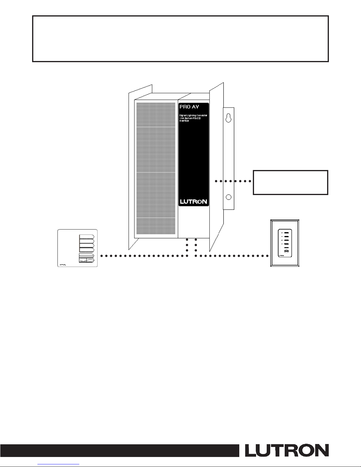
PRO AV DLC Control Units
operate up to six zones of lighting.
These units can control the intensity
of all the light sources in a room.
You can adjust the lights for any
activity with the press of a button or
from an AV Control System.
PLEASE LEAVE FOR OCCUPANT
PRO AV Digital Lighting Controller (DLC)
Installation Guide
Models PAV6M-120/PAV6S-120 PAV6M-230/PAV6S-230
IMPORTANT!
■ Pro AV DLC lighting controls must be installed by a qualified electrician in accordance with all applicable regulations. Improper wiring can result in
personal injury or damage to Pro AV lighting controls or other equipment.
■ Always turn off circuit breaker/MCB or remove main fuse from power line before doing any work.
■ To avoid overheating and possible damage to equipment, do not install dimming devices to dim receptacles, motor-operated appliances, or dimmable
fluorescent lighting not equipped with Lutron Hi-Lume
®
, Eco-10™, or Tu-Wire™Electronic Dimming Ballasts.
■ When used with Low Voltage lighting, do not remove factory-installed bypass jumpers on load circuit terminals until load circuits are tested (see start-up
procedure on page 6.)
■ The Pro AV DLC dimming modules are designed to operate in ambient temperatures between 0 °C-40 °C (32 °F-104 °F).
■ To reduce the risk of overheating and possible damage to other equipment, the module must be mounted as shown. Failure to provide adequate space for
cooling may result in overheating and void the warranty.
■ Module hums slightly during operation and the internal relay clicks when the circuit is turned on and off. Choose an installation location where these
sounds are acceptable.
■ When used with low-voltage lighting, do not operate Pro AV DLC lighting controls with any lamps removed or burned out; Replace any burned out lamps
immediately. Use only low-voltage transformers that incorporate thermal protection or fused primary windings.
■ Pro AV DLC lighting controls are designed for commercial indoor use only.
■ This control uses Class 2/PELVwiring methods. Check with your local electrical inspector for compliance with national and local codes and wiring
practices.
(US Models)
(CE Models)
AVControl Systems

Connections to
AV Systems?
This is an important product addition for systems integrators and A/V dealers. The PRO AV Digital Lighting Controller (DLC) meets the needs
of most small to medium size integrated spaces. The DLC is a dimming controller that can be easily incorporated into many projects. There are
several features that make this product ideal for single room applications.
The key advantage of the PRO AV DLC is function. It is a self-contained complete lighting control package. It has 6 zones of 800 W dimming
capacity* with 16-scene programming capability and an integral RS232 input.
The PRO AV DLC improves coordination of lighting control. It is a simple-to-install system that can operate on its own providing basic lighting
control function until the AVsystem is installed or when the AV system is not needed.
All programming of the PRO AV DLC is done via the RS232 interface and the system integrator’s control system. The DLC will operate with
Lutron’s Liaison Software or from programs generated in AMX, Crestron or other Software.
* Not all zones need to be connected; however, connected zones must have a load of at least 25W (40W for CE models). No zone may be
loaded with more than 800 W. Maximum load capacity for Control Unit is 2,000 W (2300 W for CE). Unit must not carry more than 16A of
total lighting load (10A for CE models).
Description
Do you have: Then read this . . . . . . on page:
Control Unit only? STEP 1: Installing PRO AV DLC Series Control Units..................................................................3
Follow Step 1 and Step 3
How to Wire and mount PRO AV DLC Series Control Units.
Wallstations? STEP 2: Wiring Instructions ............................................................................................................4
Control Unit Mounting and Wiring
STEP 3: Installing Wallstation Controls........................................................................................5
Setting DIP Switches, Mounting, and Wiring.
STEP 4: Start-up Procedure..............................................................................................................6
Testing circuits, removing bypass jumpers.
STEP 5: RS232 Wiring........................................................................................................................7
RS232 Wiring programming.
STEP 6: Setting up PRO AV DLC Control Units ............................................................................7
Setting address and assigning Wallstations to Control Units.
STEP 7: Setting up RS232 Communication ..................................................................................8
DIP Switch setting of Control Unit Interface Board.
Questions about Appendix A: More about Class 2/PELV Wiring ..........................................................................10
Class 2/PELV Wiring?
Adding more Wallstations? Appendix B: Installing an External Power Supply ..................................................................10
Adding more power? Appendix C: Power Boosters and Load Interfaces ..................................................................11
Appendix D: GRX-TVI 0-10 Volt Ballast Interface ....................................................................12
Adding large loads? Appendix E: HP Dimming Modules................................................................................................13
Adding Control? Appendix F: Infrared Transmitters/Receivers............................................................................14
Problems? Appendix G: Troubleshooting ........................................................................................................14
Page 2
Adding Fluorescent Dimmed or Nondimmed loads?
Page 3
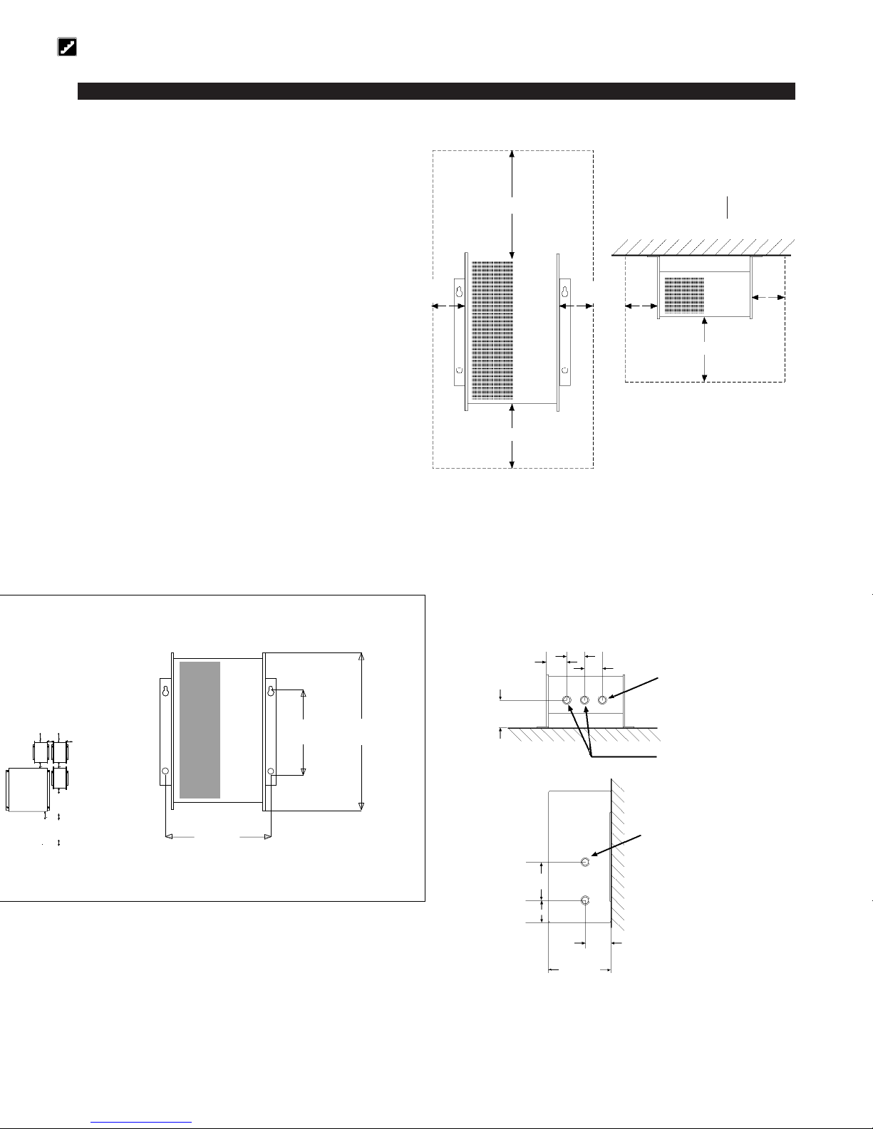
2''
(51 mm)
Class 2/PELV wiring must enter
through this knockout.
Bottom View
2.188''
(56 mm)
2''
(51 mm)
3''
(76 mm)
Right Side View
RS232 wiring must enter
through this knockout.
4.125''
(104 mm)
2.375''
(60 mm)
5.875”
(150 mm)
2.875''
(73 mm)
Mounting Dimensions
14.5''
(368 mm)
9.25''
(253 mm)
9.375''
(238 mm)
1. Choose an appropriate location.
Select a convenient location, such as an electrical closet AV
room or above a ceiling (non-plenum). Make sure location is
at least 6’ from sensitive AV equipment (and its wiring). Also,
make sure to locate module where its slight noise (relays
clicking and slight humming) is acceptable. Ensure ambient
temperatures are between 32 °F-104 °F (0 °C-40 °C). Module
must be mounted away from steam pipes, direct sunlight, or
other heat sources.
2. Plan placement of modules.
Modules must be mounted vertically. Make sure that nothing
blocks the air channel between the back of the module and the
wall.
■ Leave 6” (152 mm) of space above and below modules and
3” (76 mm) of space on either side of modules.
■ Leave 10” (204 mm) between the top of the module and the
ceiling, and 6” (152 mm) between the bottom of the module
and the floor.
■ Leave 6” (152 mm) of clearance in front of each module.
3. Mount modules (see below).
Using the mounting dimensions shown below, mark (while keeping the module vertical), then drill mounting holes.
Securely fasten the module to the wall. Top mounting holes are keyed to facilitate mounting.
Airspace Required
Front View
Top View
Air Channel
3''
(76 mm)
6'' (153 mm)
10'' (254 mm)
3''
(76 mm)
3''
(76 mm)
3''
(76 mm)
6'' (153 mm)
Step 1: Installing PRO AV DLC Series Control Units
This section shows how to install the PRO AV DLC.
Mounting and Dimensions
Load wiring must enter through
these knockouts.
Page 4
Line Voltage/Mains Wiring. First, turn power off.
WARNING: Turn power OFF to all circuits before installing any part of the Dimming System. Wiring with the power on can result in
serious personal injury or damage to equipment.
1. Pull dedicated feeds.
Each Pro AV DLC control unit requires a 20A dedicated feed.
2. Power and control wires must be run in separate conduit or
raceways. Run individual neutrals for input and each load
circuit.
3. 15A circuit breakers may be used in place of 20A circuit
breakers. Do not exceed 1440W per 15A circuit.
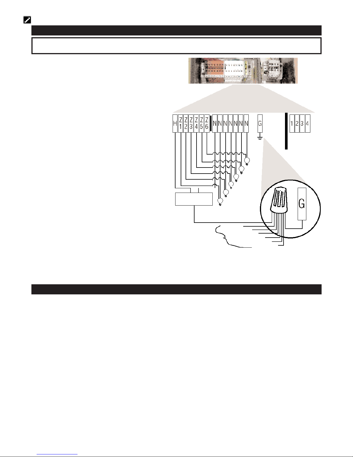
4. Connect HOT load wires to terminals Z1-Z6. Connect all load
neutrals to the neutral terminals (N1-N6).
Load wiring differs depending on the load type and whether the load is
dimmed or switched (see below). Loads that require an interface, such
as fluorescent, electronic low voltage, switched loads, 277V loads, and
loads exceeding 800W/zone - Refer to Appendix C wiring diagrams with
interface.
Load Types
The Control Units can control incandescent, halogen (tungsten), magnetic
low-voltage, and neon/cold cathode load types. Electronic low-voltage and
fluorescent load types can be controlled with an appropriate interface.
■ Not all zones need to be connected; however, connected zones must
have a load of at least 25W (40 W for CE models).
■ No zone may be loaded with more than 800 W. Maximum load capacity
for Control Unit is 2,000 W (2300 W for CE).
■ Unit must not carry more than 16A of total lighting load (10A for CE
models).
■ All Electronic Low-Voltage (ELV) lighting used with the Electronic Low-
Voltage Interface must be rated for
reverse phase control dimming.
Before installing an ELV light source, verify with the manufacturer that
their transformer can be dimmed.
When dimming, an Electronic Low-Voltage Interface
MUST be used with
the DLC Series Control Unit.
Step 2: Wiring Instructions
Class 2 Wiring
Connect Class 2 wiring for Wallstation Controls.
Use recommended cable as specified in Appendix A: More About Class 2/PELV Wiring.
Wiring Note
■ Use the bottom right knockout when pulling Class 2/PELV wires into the DLC (see Page 4).
1. Strip 1 in. (25 mm) of insulation from the Class 2/PELV cable.
2. Strip 3/8 in. (8 mm) of insulation from each wire.
3. Connect the Class 2/PELV wires to the Class 2/PELV terminal block. Make sure no bare wire is exposed after making connections. The
recommended installation torque is 3.5 in.●lbs. (0.4 N●m) for Class 2/PELV connections.
Ground
should not be
tied to Hot.
Class 2/PELV Terminal
Blocks for
Communications Link.
Must daisy-chain and
wire in a 1-to-1
configuration.
Zone 6
Zone 5
Zone 4
Zone 3
Zone 2
Zone 1
Ground
(1) 20A Feed
Distribution Panel
Ground from Zones 1—6
Page 5
IMPORTANT WIRING NOTES!
1. Daisy-chain the terminal 1, terminal 2, terminal 3, and terminal 4 connections to PRO AV DLC Control Units and Wallstation Controls.
2. Lutron recommends that all connections be made in the wallbox of Wallstation Controls. If a T-TAP connection is used, this remote connection must be in a
switchbox or junction box with a maximum wire length of 8 ft. (2.5m) from the T-TAP to the connected unit.
Note: Do not allow Class 2/PELV wires to contact line/mains wires.
IMPORTANT WIRING NOTES!
Review Appendix A BEFORE wiring!
■ Wallstation address must be set prior to installing Wallstations. See DIP
Switches below.
■ Wallstations use Class 2 wiring methods as applicable in your locale.
—
Using Class 2 wiring methods: Wallstations must be connected in accordance with the 1996 National Electrical Code, Article 725-54(a), (1) Exception
No. 3 or the Canadian 1994 CE Code Handbook, Rule 16-212, Subrule (4).
Check with your local electrical inspector to comply with local codes and
wiring practices.
■ Wallstations must be mounted in a wallbox. Please refer to instruction sheet
included with each Wallstation to determine wallbox requirements.
Examples of Wallstations
NTGRX-2B-SL Entrance/Special Function Control
NTGRX-4S Scene Selection Control with Raise/Lower
NTGRX-4S-IR Scene Selection Control/Infrared Receiver
NTGRX-4B Scene Selection Control
NTGRX-4M Master Control
NTGRX-4PS Partition Control
GRX-CIR Infrared Ceiling Receiver
GRX-4S-DW Architrave
TM
Door Jamb Control
GRX-AV Interface Control
EGRX-4S European Style 4S Control
EGRX-4S-IR European Style 4S Control/Infrared Receiver
. . . and more!
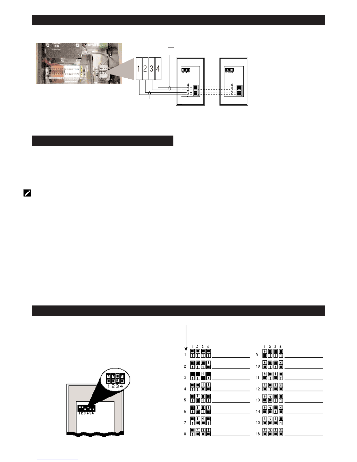
FOR THIS ADDRESS . . .
SET SWITCHES
LIKE THIS:
RECORD LOCATION
AND TYPE OF
CONTROL HERE
SET SWITCHES
LIKE THIS:
RECORD LOCATION
AND TYPE OF
CONTROL HERE
DIP SWITCHES 1—4
SET ADDRESS
Set DIP switches 1—4 with unique system address
Each Wallstation must have a
unique
system address (1—15) to identify the
Wallstation and enable it to communicate with the Control Unit(s).
To set its address, set DIP switches 1—4 to one of the configurations
shown at right. Document your assignments by noting each Wallstation’s
address. Do not use address 16.
Step 3: Installing Wallstation Controls
Do not use!
Each Control Unit can power up to two Wallstation Controls. If you need to power more than two Wallstation Controls from one Control Unit, install an external
12VDC power supply as described on page 13.
Small project: A Control Unit with up to two Wallstations Controls
Maximum of 1000 ft. (300 m) between the PRO AV DLC Control Unit and the second Wallstation. For longer distances, use an external Class 2/PELV rated
12VDC power supply (see Page 4).
WALLSTATION
CONTROL 1
WALLSTATION
CONTROL 2
DATA LINK:
4: MUX
3: MUX
Class 2/PELV Terminal Blocks for
communications link. Must daisy-chain and
wire in a 1-to-1 configuration.
CLASS 2
POWER WIRING:
2: 12VDC
1: COMMON
 Loading...