

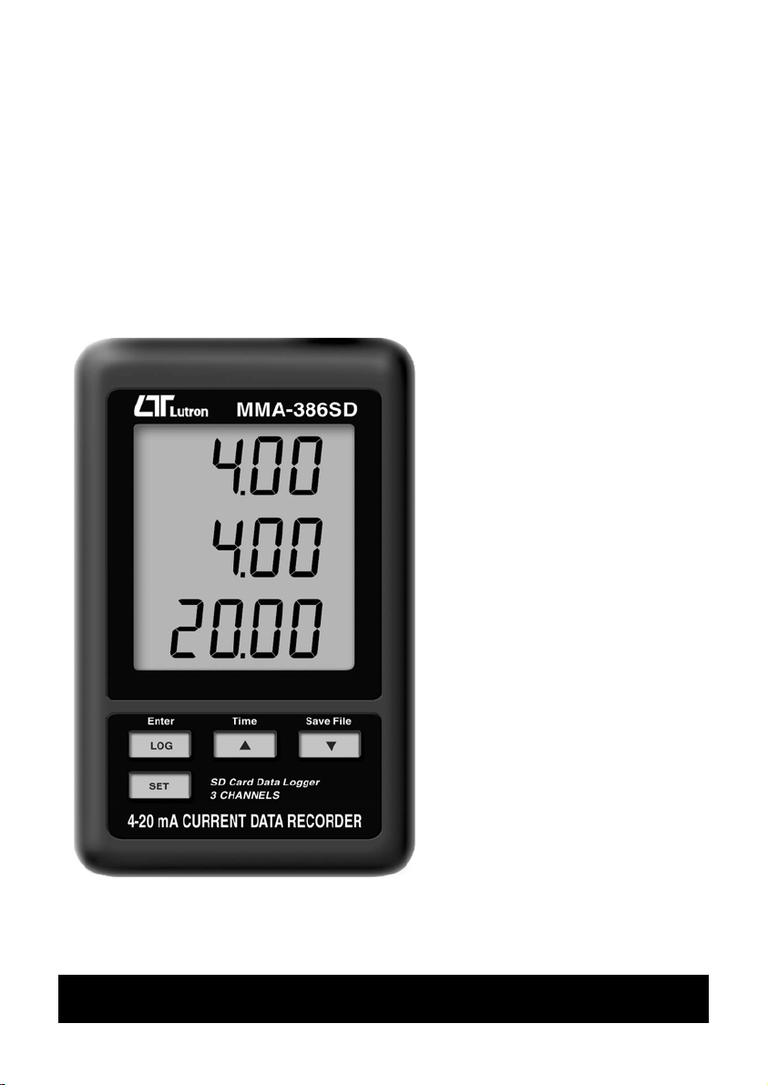
Lutron Electronics MMA-386SD Operation Manual
SD card real time datalogger
Your purchase of this 3
3 channels 4-20 mA
CURRENT RECORDER
Model : MMA-386SD
channels 4-20 mA
CURRENT RECORDER
marks a step forward for
you into the field of
precision measurement.
Although this DATA
RECORDER is a complex
and delicate instrument,
its durable structure will
allow many years of use
if proper operating
techniques are
developed. Please read
the following
instructions carefully
and always keep this
manual within easy
reach.
OPERATION MANUAL

TABLE OF CONTENTS
gg
g
ging
.
ging
g
g
g
gg
gg
.
g
.
g
.
1. FEATURES............................................................................... 1
2. SPECIFICATIONS..................................................................... 2
3. FRONT PANEL DESCRIPTION.................................................... 4
3-1 Display.............................................................................. 4
3-2 Lo
3-3 Button ( Time Button )...................................................▲ 4
3-4 Button ( Back Li
3-5 SET Button........................................................................ 4
3-6 Han
3-7 Stand................................................................................ 4
3-8 Battery cover/Battery compartment..................................... 4
3-9 Screw of the battery cover.................................................. 4
3-10 4-20 mA input socket ( CH 1 )........................................... 4
3-11 4-20 mA input socket ( CH 2 )........................................... 4
3-12 4-20 mA input socket ( CH 3 )........................................... 4
3-13 DC 9V power adapter input socket..................................... 4
3-14 Reset Button...................................................................
3-15 RS-232 Output Terminal................................................... 4
3-16 SD card socket................................................................. 4
3-17 Han
3-18 4-20 mA input plu
3-19 4-20 mA input plu
3-20 4-20 mA input plu
4. MEASURING PROCEDURE......................................................... 6
5. DATALOGGER.......................................................................... 7
5-1 Preparation before execute datalo
5-2 Datalo
5-3 Check time information......................................................
5-4 SD Card Data structure.......................................................10
6. Savin
7. ADVANCED SETTING...............................................................
7-1 SD memory card Format.....................................................13
7-2 Set clock time ...................................................................13
7-3 Set samplin
7-4 Set beeper sound ON/OFF..................................................14
7-5 Set SD card Decimal character............................................15
7-6 Set RS232 data output ON/OFF...........................................16
8. POWER SUPPLY from DC ADAPTER........................................... 16
9. BATTERY REPLACEMENT..........................................................16
10. SYSTEM RESET......................................................................17
11. RS232 PC serial interface........................................................17
12. PATENT................................................................................
er Button ( Enter Button )............................................ 4
ht Button )...........................................▼ 4
holes....................................................................4
4
unit ( with sticker ).............................................. 4
( CH 1 ).............................................. 4
( CH 2 ).............................................. 4
( CH 3 ).............................................. 4
er function.................... 7
er.........................................................................9
10
data from the SD card to the computer...........................11
12
time..............................................................14
19

1. FEATURES
* 4-20 mA current loop recorder with real time
data logger, save the measuring data along
the time information ( year, month, date, hour,
minute, second ) into the SD memory card
and can be downloaded to the Excel, extra
software is no need.
* Input signal : 4 to 20 mA, 3 channels.
* Resolution : 0.01 mA.
* Input channels : 3 channels.
* Show 3 channels ( CH1, CH2, CH3 ) 4-20 mA
current loop values in the same LCD.
* Records time and date along with 4-20 mA DC
current measurement value from external sensors,
transducers and many other sources.
* Applications :
4 to 20 mA recording
pH recording
Low level signal monitoring
Photovoltaic studies
Battery studies
Biological sensor monitoring
Factory process control
Research and development
Medical and Pharmaceutical
Environmental studies
* Large LCD display, easy readout.
* Low power consumption and long battery life
when using battery power.
* DC 1.5V ( UM-4/AAA ) battery x 6 PCs or
optional DC 9V adapter in.
* RS232/USB computer interface.
1
2. SPECIFICATIONS
Circuit Custom one-chip of microprocessor LSI
circuit.
Display LCD size : 60 mm x 50 mm
Memory Card SD memory card. 1 GB to 16 GB.
Measurement 0 to 20 mA
Signal
CH1, CH2, CH3
Accuracy ± ( 0.5% + 0.02 mA )
Resolution 0.01 mA.
Datalogger 5/10/30/60/120/300/600 seconds
Sampling Time
Data error no. 0.1 % no. of total saved data typically.≦
Advanced * SD memory card Format
setting * Set clock time ( Year/Month/Date, Hour/Minute/
Second )
* Set sampling time
* Set beeper sound ON/OFF
* Set SD card Decimal character
* Set RS232 data output ON/OFF
Update Time Approx. 1 second if measuring data
of Display is changed.
Data Output RS 232/USB PC computer interface.
* Connect the optional RS232 cable
UPCB-02 will get the RS232 plug.
* Connect the optional USB cable
USB-01 will get the USB plug.
Operating 0 to 50 .℃
Temperature
Operating Less than 85% R.H.
Humidity
2

Power Supply Alkaline or heavy duty DC 1.5 V battery
( UM4, AAA ) x 6 PCs, or equivalent.
or DC 9V adapter input. ( AC/DC power
adapter is the optional accessory ).
* Batterries are also the clock backup
power source, so if use AC to DC
adapter power supply, it is
recommend to install the batteries
at any time.
Weight 199 g/0.44 LB.
Dimension 132 x 80 x 32 mm
( 5.2 x 3.1 x 1.3 inch )
Accessories * Instruction manual........................1 PC
Included * Hanging unit ( with sticker )..........1 PC
* Wire plug for input socket.............3 PCs
Optional * AC to DC 9V adapter.
Accessories
* SD Card ( 4 GB ).
* USB cable, USB-01.
* RS232 cable, UPCB-02.
* Data Acquisition software, SW-U801-WIN.
* Excel Data Acquisition software, SW-E802.
3
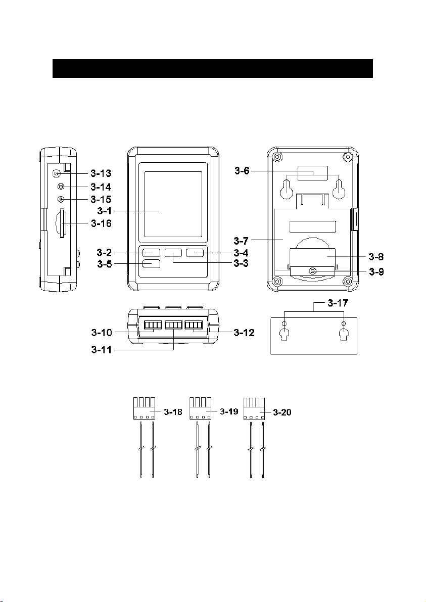
3. FRONT PANEL DESCRIPTION
Fig. 1
4

3-1 Display
3-2 Logger button ( Enter button )
3-3 Button ( Time Button )▲
3-4 Button ( Back Light Button )▼
3-5 SET Button
3-6 Hanging holes
3-7 Stand
3-8 Battery cover/Battery compartment
3-9 Screw of the battery cover
3-10 4-20 mA input socket ( CH 1 )
3-11 4-20 mA input socket ( CH 2 )
3-12 4-20 mA input socket ( CH 3 )
3-13 DC 9V power adapter input socket
3-14 Reset Button
3-15 RS-232 Output Terminal
3-16 SD card socket
3-17 Hanging unit ( with sticker )
3-18 4-20 mA input plug ( CH 1 )
3-19 4-20 mA input plug ( CH 2 )
3-20 4-20 mA input plug ( CH 3 )
5
 Loading...