

Page 1
Installation
ON
OFF
ON
OFF
ON
OFF
Turning OFF power.
• Turn power OFF at circuit breaker (or remove fuse).
11
Removing wallplate and
switch.
• Remove the wallplate and switch mounting screws.
• Carefully remove switch from wall (do not remove wires).
22
Disconnecting switch wires.
33
Wiring.
• For installations involving more than one control in a wallbox,
refer to Multigang Installations before beginning.
44
55
ON
OFF
ON
OFF
ON
OFF
Turning ON power.
• Turn power ON at circuit breaker (or replace fuse).
66
Lutron Electronics Co., Inc.
7200 Suter Road
Coopersburg, PA 18036-1299, U.S.A.
Made and printed in the U.S.A.
6/09 P/N 030-1041 Rev. A
To learn about the Advanced Featuresof
Maestro
Wall Controls including locked preset
and timer bypass disable, please visit: www.lutron.com/maestro/advfeatures or call
the
Lutron Technical Support Center
at 1.800.523.9466.
?
Technical Assistance
If you have questions concerning the installation or operation of this
product, call the
Lutron Technical Support Center
. Please provide
exact model number when calling.
U.S.A. and Canada (24 hrs/7days)
1.800.523.9466
México
+1.888.235.2910
Other countries 8am – 8pm ET
+1.610.282.3800
Fax +1.610.282.6311
http://www.lutron.com
030-1041
030-1041
Screw Terminals:
Turn screws to loosen.
Push-in Terminals:
Insert screwdriver.
Pull wire out.
Wiring the Timer:
• Using the wire connector
provided, connect the green
ground wire on the Timer to the
bare copper or green ground
wire in the wallbox.
• Connect either of the wires
removed from the switch to one
of the brass screw terminals on
the Timer,or insert fully into the
push-in terminal.
• Connect the remaining wire
removed from the switch to the
other brass screw terminal on
the Timer,or insert fully into the
push-in terminal.
Ground
Green wire
Brass screw
Live
120 V~
60 Hz
Neutral
Brass
Brass
Green wire
Ground
Wallbox
Timer
Reference Wiring Diagram
Brass screw
Important Note:
Your wall switch may have two wires attached to the same screw (see
illustrations below for examples). Tape these two wires together before
disconnecting. When wiring, connect wires to the Timer the same way they
were connected to the switch.
One wire in
the push-in
terminal hole
and one to
the screw.
One
continuous
wire to the
screw.
Looped Wire:
Turn screw to
loosen.
Turn screws
to loosen.
Lutron Technical Support Center 1.800.523.9466 24 hrs / 7 days www.lutron.com
Multigang Installations
When installing more than one control in the same wallbox, it may be
necessary to remove all inner side sections prior to wiring (see below). Using
pliers, bend side sections up and down until they break off. Repeat for each
side section to be removed. Removal of Timer side sections reduces maximum
load capacity. Refer to chart below for maximum Timer capacity.
Breaking Side Sections
Limited Warranty
(Valid only in U.S.A., Canada, Puerto Rico,and the Caribbean.)
Lutron will, at its option, repair or replace any unit that is defective in materials or manufacture within
one year after purchase. For warranty service, return unit to place of purchase or mail to Lutron at
7200 Suter Rd., Coopersburg, PA 18036-1299, postage pre-paid.
THIS WARRANTY IS IN LIEU OF ALL OTHER EXPRESS WARRANTIES, AND THE IMPLIED
WARRANTY OF MERCHANTABILITY IS LIMITED TO ONE YEAR FROM PURCHASE.THIS WARRANTY
DOES NOT COVER THE COST OF INSTALLATION,REMOVAL OR REINSTALLATION,OR DAMAGE
RESULTING FROM MISUSE,ABUSE, OR DAMAGE FROM IMPROPER WIRING OR INSTALLATION.
THIS WARRANTY DOES NOT COVER INCIDENTAL OR CONSEQUENTIAL DAMAGES.LUTRON’S
LIABILITY ON ANY CLAIM FOR DAMAGES ARISING OUT OF OR IN CONNECTION WITH THE
MANUFACTURE, SALE,INSTALLATION, DELIVERY,OR USE OF THE UNIT SHALL NEVER EXCEED THE
PURCHASE PRICE OF THE UNIT.
This warranty gives you specific legal rights, and you may have other rights which vary from state to
state. Some states do not allow the exclusion or limitation of incidental or consequential damages, or
limitation on how long an implied warranty may last, so the above limitations may not apply to you.
This product is covered under one or more of the following U.S. patents: 7,190,125; 7,365,282;
7,546,473 and corresponding foreign patents. U.S. and foreign patents pending.Lutron, Claro, Maestro
and Satin Colors are registered trademarks, and FASS is a trademark of Lutron Electronics Co.,Inc.
NEC is a registered trademark of the National Fire Protection Association, Quincy,Massachusetts.
© 2009 Lutron Electronics Co., Inc.
No Sides
Removed
600 W
600 VA / 450 W
3 A
1 Side
Removed
500 W
500 VA / 400 W
3 A
2 Sides
Removed
400 W
400 VA / 300 W
3 A
English
Maximum Load
Do Not Remove
Outside Sections
Each Control Has
Inside Section
Removed
Middle Control Has Two
Side Sections Removed
Important Notes
Please read before installing.
1. CAUTION! To avoid overheating and possible damage to other
equipment, do not use to control receptacles, fluorescent lighting
fixtures, motor-operated or transformer-supplied appliances.
2. Install in accordance with all national and local electrical codes.
3. Do not use for loads switched from 2 or more locations.
4. DO NOT use Maestro®controls for compact fluorescent lamps.
5. When no “grounding means” exist within the wallbox then the NEC
®
2008, Article 404-9 allows a control without a grounding connection to
be installed as a replacement, as long as a plastic, noncombustible
wallplate is used. For this type of installation, cap or remove the green
ground wire on the control and use an appropriate wallplate such as
Lutron’s Claro®or Satin Colors®series wallplates.
6. Protect Timer from dust, dirt, and paint when spackling or painting.
7. Do not use where total load current is less than 0.3 A or greater than
5 A (see Timer Capacity Chart for details).
8. Operate between 0 °C (32 °F) and 40 °C (104 °F).
9. Timer may feel warm to the touch during normal operation.
10. Recommended wallbox depth is 2 ½in (64 mm) minimum.
11. For safety reasons, do not use to control fixtures that are the only
source of illumination for an area.
12. When controlling a combined fan and light load, the total load may not
exceed 3 A.
13. Clean Timer with a
soft damp cloth only
. Do not use any chemical cleaners.
Countdown Timer
MA-T51
120 V 60 Hz 5 A Lighting* or 3 A Fan
MA-T530G
120 V 60 Hz 5 A Lighting* or 3 A Fan
Important Wiring Information
When making wire connections, follow the recommended strip lengths and
combinations for the supplied wire connector. Note: All wire connectors
provided are suitable for
copper wire only.
For aluminum wire, consult an
electrician.
Wire Connector:
Use to join one 12 AWG or 14 AWG
(2.5 or 1.5 mm
2
) ground wire with one
18 AWG (0.7 mm
2
) control ground wire.
Twist wire
connector
tight.
Push-in Terminals: Insert wires fully.
NOTE: Push-in terminals are for use with 14 AWG
(1.5 mm2)
solid copper wire only.
DO NOT use stranded or
twisted wire.
Screw Terminals: Tighten securely.
Screw terminals are for use with 12 or 14 AWG
(2.5 or 1.5 mm2)
solid copper wire only.
DO NOT use
stranded or twisted wire.
Trim or strip wallbox wires to the length indicated by the strip gauge on the back of the control
OR
Symptom
Load does not turn
ON or no LEDs turn
ON.
Possible Cause
• Front Accessible Service Switch (FASS
TM) on
Timer is pulled out to OFF
• Light bulb(s) burned out.
• Breaker is off or tripped.
• Wiring error. Call
Lutron Technical Support Center
Troubleshooting
IMPORTANT NOTICE:
To replace bulb,remove po wer by pulling the
FASS
switch out on the Control.
For any procedure other than routine bulb replacement, power must be
disconnected at the main electrical panel.
Load Type
Halogen/Incandescent
120 V~
Magnetic Low Voltage**
General Purpose Fan
Mounting Control(s) to wallbox.
• Form wires carefully into wallbox, mount and align control(s).
• Install the wallplate(s
).
Load turns on and off
repeatedly.
• Load draws less than 0.3 A or 40 W
• Improper load connected
Light or
Fan
Fixture(s)
**Note: The maximum lamp wattage is determined by the efficiency of the transformer, with 70–85% as
typical. For actual transformer efficiency, contact either the fixture or transformer manufacturer. The total VA
rating of the transformer(s) shall not exceed the VA rating of the timer.
Note: Do not overtighten mounting screws. Permanent damage
can be caused by overtightening mounting screws.
Snap on Claro
wallplate.
Start screws.
Align control and
tighten screws.
*See Timer Capacity Chart.
Timer Capacity Chart
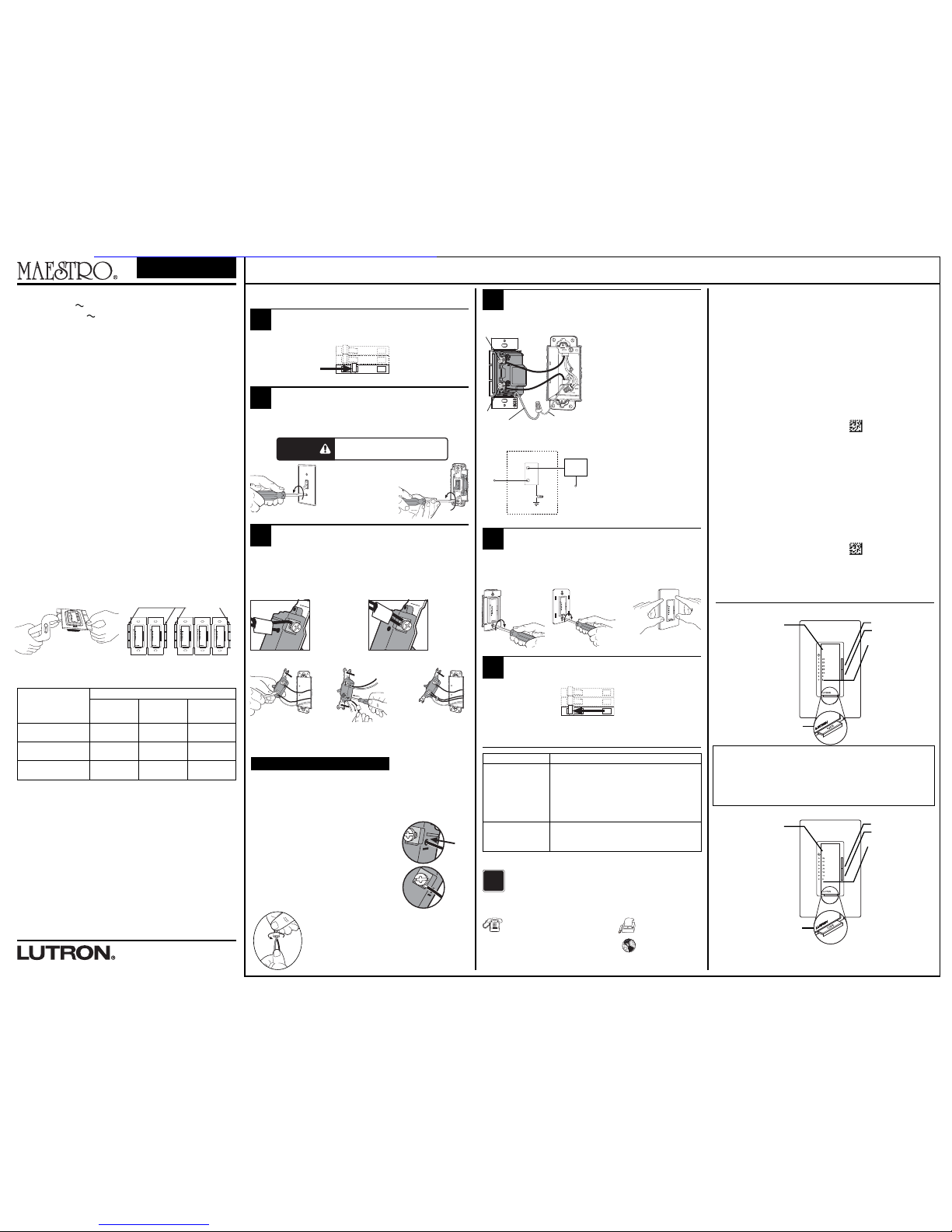
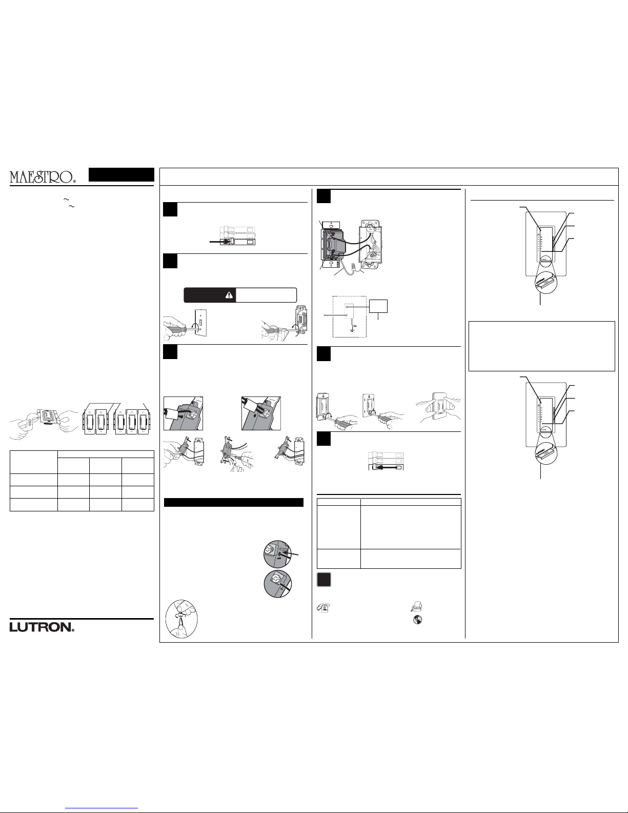
Operation
Tap Button Options
• Tap once when unit is off
Controlled load turns ON
and countdown timer begins.
When time expires, load turns OFF.
• Tap once when unit is on -
Controlled load turns OFF
and countdown timer resets.
• Tap twice quickly -
Controlled load turns on with
30 minute countdown timer.
Press to increase time
Press to reduce time
LEDs
• Orange LEDs indicate
timer duration or
remaining time in
minutes
• Bottom LED blinks
slowly to indicate 1
minute of time
remaining.
FASS
- Front Accessible
Service Switch
One Minute Indication:
When only one minute of time is remaining, the load will briefly turn off and on to give
an indication the timer is about to turn off.
MA-T530G
Tap Button Options
• Tap once when unit is off
Controlled load turns ON
and countdown timer begins.
When time expires, load turns OFF.
• Tap once when unit is on -
Controlled load turns OFF
and countdown timer resets.
• Tap twice quickly -
Controlled load turns on
without a time limit
Press to increase time
Press to reduce time
LEDs
• Orange LEDs indicate
timer duration or
remaining time in
minutes
• Top green LED labeled
On has no time limit
• Bottom LED blinks
rapidly to indicate 1
minute of time
remaining.
FASS
- Front Accessible
Service Switch
MA-T51
WARNING
Shock Hazard. May result in serious injury or
death. Turn off power at circuit breaker before
installing unit.
http://waterheatertimer.org/Countdown-timer-horsepower-ratings.html
Page 2
Sin laterales
extraídos
600 W
600 VA / 450 W
3 A
1 sección
lateral
removida
500 W
500 VA / 400 W
3 A
Carga Máxima
Tipo de carga
Halógeno/Incandescent
de 120 V~
BVM**
Ventilador para usos
generales
**Nota: La potencia máxima de las lámparas está determinada por la eficiencia del transformador, siendo
70-85% lo típico. Para conocer sobre la eficiencia real, contacte al fabricante del artefacto o del
transformador. La estimación total de VA del transformador(es) no debe exceder los VA del temporizador.
Cuadro de Capacidad del Temporizador
Instalación
ON
OFF
ON
OFF
ON
OFF
Apagado.
• Desconecte la alimentación en el cortacircuito (o quite el fusible).
11
Remoción de la placa de
pared y el interruptor.
• Retire la placa y los tornillos de montaje del interruptor.
• Retire el interruptor de la pared con cuidado (no saque los cables).
22
Desconexión de los cables
del interruptor.
33
Cableado.
• Consulte la sección Instalaciones con varios componentes
cuando tenga más de un control en una caja de empotrar.
44
55
ON
OFF
ON
OFF
ON
OFF
Encendido.
• Encienda desde el cortacircuito (o vuelva a colocar el fusible).
66
Lutron Electronics Co., Inc.
7200 Suter Road
Coopersburg, PA 18036-1299 E.U.A.
Hecho e impreso en los Estados Unidos
6/09 P/N 030-1041 Rev.A
Para conocer más acerca de las Funciones Avanzadas de Los Controles de Pared
Maestro
incluyendo predeterminado bloqueado y deshabilitación del sobrecontrol del
temporizador,visite: www.lutron.com/maestro/advfeatures o llame al
Centro de
Soporte Técnico de Lutron
?
Asistencia Técnica
Si usted tiene alguna duda con respecto a la instalación o al funcionamiento
de este producto, comuníquese con el
Centro de Soporte Técnico de
Lutron
. Por favor,indique el modelo exacto al llamar.
E.U.A. y Canadá (24 horas/7 días a la semana)
1.800.523.9466
México
+1.888.235.2910
Otros países 8 a.m. – 8 p.m. (Hora del Este)
+1.610.282.6701
Fax +1.610.282.6311
http://www.lutron.com
Bornes de Tornillos:
Afloje los tornillos.
Bornes a presión:
Inserte el
destornillador. Tire el
cable hacia fuera.
Cableado del Temporizador:
• Utilice el conector de cables
provisto para conectar el cable
de descarga a tierra verde del
Temporizador al cable de
descarga a tierra de cobre sin
aislamiento, o al cable a tierra
verde de la caja de empotrar.
• Conecte uno de los cables
extraídos del interruptor a uno
de los bornes de tornillo de
latón en el Temporizador, o
insértelo completo en el borne a
presión.
• Conecte el cable restante
extraído del interruptor al otro
borne de tornillo de latón del
Temporizador, o insértelo
completo en el borne a presión.
Tierra
Cable verde
Tornillo de
latón
Vivo
120 V~
60 Hz
Neutro
Latón
Latón
Cable
verde
Tierra
Caja de empotrar
Reloj
Diagrama de Referencia de Cableado
Tornillo de latón
Nota importante:
Su interruptor de pared puede tener dos cables conectados al mismo borne
de tornillo (vea los ejemplos ilustrados a continuación). Una ambos cables
con cinta adhesiva antes de desconectarlos. Cuando realice el cableado,
conecte los cables al Temporizador de la misma forma que estaban
conectados al interruptor.
Un cable en
el orificio del
borne a
presión y uno
al tornillo.
Un cable
continuo al
tornillo.
Cable Enrulado:
Gire el cable para
aflojarlo.
Afloje el
tornillo.
Centro de Soporte Técnico de Lutron +1.888.235.2910 horas / 7 días por semana www.lutron.com
Instalaciones con varios dispositivos
Cuando se instala más de un control en la misma caja de empotrar,puede ser
necesario retirar todas las secciones laterales internas antes de cablear (ver más
abajo). Utilizando pinzas, doble las secciones laterales hacia arriba y hacia abajo hasta
que se quiebren. Repita para cada sección lateral a retirar.La remoción de las
secciones laterales del Temporizador reduce la capacidad de carga máxima.Consulte
el cuadro más abajo para la capacidad máxima del Temporizador.
Quiebre de las
secciones laterales
Garantía Limitada
(Válido solamente en los E.U.A., Canadá, Puerto Rico y el Caribe.)
Lutron, a discreción propia, reparará o reemplazará las unidades con fallas en sus materiales o
fabricación dentro del año posterior a la compra de las mismas. Para obtener el servicio de garantía,
remita la unidad al lugar donde la adquirió o envíela a Lutron, 7200 Suter Rd., Coopersburg,PA
18036-1299, con servicio postal prepago.
ESTA GARANTÍA REEMPLAZA A TODA OTRA GARANTÍA EXPRESA Y LA GARANTÍA IMPLÍCITA DE
COMERCIABILIDAD ESTÁ LIMITADA A UN AÑO DESDE LA FECHA DE COMPRA.ESTA GARANTÍA NO
CUBRE EL COSTO DE INSTALACIÓN,DE REMOCIÓN NI DE REINSTALACIÓN, NI LOS DAÑOS
PROVOCADOS POR USO INCORRECTO O ABUSO NI LOS DAÑOS RESULTANTES DE UN CABLEADO O
UNA INSTALACIÓN INCORRECTOS.ESTA GARANTÍA NO CUBRE DAÑOS INCIDENTALES O
INDIRECTOS. LA RESPONSABILIDAD DE LUTRON ANTE UNA DEMANDA POR DAÑOS CAUSADOS
POR O RELACIONADOS CON LA FABRICACIÓN,VENTA, INSTALACIÓN, ENTREGA O USO DE LA
UNIDAD NO EXCEDERÁ EN NINGÚN CASO EL PRECIO DE COMPRA DE LA UNIDAD.
La presente garantía le otorga derechos legales específicos y usted puede tener otros derechos que
varían según el estado. Algunos estados no admiten la exclusión o limitación de los daños incidentales
o indirectos, ni las limitaciones en la duración de las garantías implícitas, de modo que las
limitaciones anteriores pueden no ser aplicables en su caso.
Este producto está cubierto por una o más de los siguientes patentes de E.U.A.: 7,190,125;
7,365,282; 7,546,473 y las correspondientes patentes extranjeras. Patentes de E.U.A. y extranjeras
pendientes. Lutron, Claro,Maestro, Satin Colors y FASS son marcas registradas de Lutron Electronics
Co., Inc. NEC es una marca registrada de National Fire Protection Association,Quincy, Massachusetts.
© 2009 Lutron Electronics Co., Inc.
2 secciones
laterales
removidas
400 W
400 VA / 300 W
3 A
Español
No retire las secciones
exteriores
Cada Control tiene
una sección lateral
removida
Al control del medio se le
han quitado ambas
secciones laterales
Notas importantes
Por favor lea antes de instalar.
1. CUIDADO! Para evitar el sobrecalentamiento y daño posible a otros equipos, no
utilice para controlar los receptáculos, guarniciones de iluminación fluorescente,
herramientas operadas por motor o abastecidas por transformador.
2. La instalación se debe realizar de acuerdo con todas las reglamentaciones de
los códigos eléctricos nacionales y locales.
3. No utilice para cargas conmutadas desde 2 o más ubicaciones.
4. NO use controles Maestro
® para lámparas fluorescentes compactas.
5. Cuando no existen “medios de descarga a tierra” dentro de la caja, el NEC®
2008, Artículo 404-9 permite que se instale como reemplazo un control sin
conexión a tierra, siempre y cuando se utilice una placa de pared de plástico no
inflamable. Para este tipo de instalación,cubra o quite el cable a tierra verde del
control y use una placa apropiada, como las de la serie de placas Claro™o Satin
Colors™de Lutron.
6. Proteja el temporizador del polvo, la suciedad y la pintura al revocar o pintar.
7. No lo utilice cuando la corriente de carga total es menor a 0,3 A o mayor a 5 A
(vea la Tabla de Capacidad del Temporizador para obtener detalles).
8. Mantenga entre los 0 °C (32 °F) y los 40 °C (104 °F) de temperatura.
9. Es posible que el temporizador esté caliente al tacto durante el
funcionamiento normal.
10. La profundidad de caja recomendada es de 64 mm (2 ½ pulgadas) mínimo.
11. Por razones de seguridad, no lo utilice para controlar artefactos que son la única
fuente de iluminación para un área.
12. Cuando se controla un ventilador y una carga de luz combinados, la carga total
no debe exceder los 3 A.
13. Limpie el Temporizador con un
paño suave húmedo solamente
. No utilice
productos químicos de limpieza.
Interruptor con Temporizador
MA-T51 Luz* de 120 V 60 Hz 5 A o Ventilador de 3 A
MA-T530G Luz* de 120 V 60 Hz 5 A o Ventilador de 3 A
Información importante sobre cableado
Cuando se hagan las conexiones de los cables, la sección sin aislamiento debe
respetar las combinaciones y longitudes recomendadas para el conector de
cable provisto. Nota: Todos los conectores de cable ya provistos son para
cable
de cobre solamente.
Para cable de aluminio, consulte a un electricista.
Conector de cable:
Úselo para unir un cable de tierra 2,5 o 1,5 mm
2
(12 o 14 AWG) con un cable de tierra 0,75 mm
2
(18 AWG) del control.
Conector
de cable
trenzado
ajustado.
Borneras a presión: Inserte los cables completamente.
NOTA: Los terminales a presión sólo se utilizan con
cables
de
1,5 mm2 (14 AWG)
cobre sólido.
NO utilice cable
retorcido ni trenzado.
Bornes de Tornillo: Ajuste con firmeza.
Los bornes de tornillo se deben usar únicamente con
cables de cobre sólido
2,5 o 1,5 mm2(12 o 14 AWG)
.
NO utilice cable retorcido ni trenzado.
Recorte o pele los cables de la caja de empotrar hasta la medida indicada en el reverso
del control.
O
Síntoma
La carga no se
ENCIENDE o no se
ENCIENDEN los
indicadores LED.
Posible causa
• La posición de apagado del Interruptor de
Servicio Accesible desde el Frente (FASS
TM) del
Temporizador es hacia fuera
• La(s) lámpara(s) está(n) quemada(s).
• El cortacircuito está apagado o se disparó.
• Error de cableado. Llame al
Centro de Soporte
Técnico de Lutron
Solución de problemas
AVISO IMPORTANTE:
Para reemplazar el foco, desconecte la alimentación sacando el interruptor
FASS
hacia
afuera en el Control.
Para cualquier otro procedimiento que no sea el reemplazo de rutina del foco, la
alimentación se debe desconectar en el panel eléctrico principal.
Montaje del Control(es) en la
caja de empotrar.
• Coloque los cables cuidadosamente en la caja de empotrar, monte
y alinee el/los control(es).
• Coloque la(s) placa(s) de pared.
La carga se enciende
y se apaga
repetidamente.
•La carga libera menos que 0,3 A o 40 W
•Carga incorrecta conectada
Artefacto(s)
de Luz o de
Ventilador
Inserte la placa de
pared Claro.
Tornillos de
inicio.
Alinee el control y
ajuste los tornillos.
*Ver Cuadro de Capacidad del Temporizador.
Operación
Opciones de botones
a presión
• Presione una vez cuando
la unidad esté apagada -
La carga controlada se ENCIENDE
y comienza a funcionar el
temporizador de cuenta
regresiva.
Cuando el tiempo expira, la
carga se APAGA.
• T Dé un golpecito cuando la
unidad esté encendida -
La carga controlada se APAGA y
el temporizador de cuenta
regresiva se reinicia.
• Golpee dos veces rápidamente -
La carga controlada se ENCIENDE con
el temporizador de cuenta regresiva
en 30 minutos.
Presione para
aumentar el tiempo
Presione para reducir
el tiempo
Indicadores LED
• Los indicadores LED
anaranjados indican
la duración del
temporizador o el
tiempo restante en
minutos
• El LED del botón
inferior parpadea
lentamente para
indicar que resta 1
minuto de tiempo.
FASS
– Accesible por el frente
Interruptor de Servicio
Indicación de un minuto:
Cuando resta solamente un minuto, la carga se apagará y se encenderá brevemente
para indicar que el temporizador se está por apagar.
MA-T530G
Opciones de botones
a presión
• Presione una vez cuando
la unidad esté apagada -
La carga controlada se ENCIENDE
y comienza a funcionar el
temporizador de cuenta
regresiva.
Cuando el tiempo expira, la
carga se APAGA.
• T Dé un golpecito cuando la
unidad esté encendida -
La carga controlada se APAGA y
el temporizador de cuenta
regresiva se reinicia.
• Golpee dos veces
rápidamente -
La carga controlada se
enciende sin límite de tiempo.
Presione para
aumentar el tiempo
Presione para reducir
el tiempo
Indicadores LED
• Los indicadores LED
anaranjados indican
la duración del
temporizador o el
tiempo restante en
minutos
• El indicador LED verde
superior rotulado
Encendido no tiene
límite de tiempo.
• El LED del botón
inferior parpadea
rápidamente para
indicar que resta 1
minuto de tiempo.
FASS
– Interruptor de Servicio
Accesible por el Frente
MA-T51
ADVERTENCIA
Peligro de choque. Podría resultar en
lesiones graves o la muerte. Desconecte la
alimentación en el cortacircuito antes de
instalar el unidad.
Nota: No ajuste de más los tornillos de montaje.
Podría causar daños permanentes.
 Loading...