

Page 1
R
Setup and Maintenance Guide
Dimming and
Switching
SS yy ss tt ee mm
LCP128
TM
LCP128
TM
Page 2

Page 3
R
LCP128
TM Setup and Maintenance Guide 3
Table of Contents
Page
Overview .........................................................................................................................................................14
STEP 1: Panel Configuration ..........................................................................................................................15
STEP 2: Time Clock Configuration ..................................................................................................................22
STEP 3: Scene Modification ............................................................................................................................27
STEP 4: Control Stations.................................................................................................................................29
STEP 5: Time Clock Events.............................................................................................................................36
STEP 6: Panel Contact Closure Inputs ............................................................................................................42
STEP 7: Emergency Power Mode ...................................................................................................................46
Page
Referenced Functions
Overrides...........................................................................................................................................49
Locking and Unlocking the Controller ................................................................................................53
Troubleshooting Guide
Troubleshooting Guide.......................................................................................................................55
Maintenance
Maintenance......................................................................................................................................60
Glossary of Terms
Glossary of Terms..............................................................................................................................61
Tables
Panel Tables ......................................................................................................................................62
Module Type Table.............................................................................................................................66
Load Type Table ................................................................................................................................67
Control Location Table.......................................................................................................................68
Control Station Table .........................................................................................................................69
Time Clock Event Table .....................................................................................................................71
Reference Information
Step-by-Step Programming Instructions
Page
How to Use this Guide .........................................................................................................................................4
System Specifications ...........................................................................................................................................5
System Start-Up Checklist.....................................................................................................................................7
Controller Overview ...............................................................................................................................................9
Introduction and System Startup
e
e
s
s
d
d
o
o
p
p
p
p
t
t
o
o
u
u
s
s
l
l
o
o
s
s
o
o
i
i
k
k
s
s
i
i
l
l
h
h
i
i
t
t
k
k
,
,
e
e
t
t
a
a
o
o
n
n
d
d
r
r
i
i
c
c
o
o
t
t
t
t
i
i
o
o
n
n
ei
ei
a
a
v
v
r
r
y
y
e
e
i
i
!
!
l
l
e
e
t
t
M
M
n
n
e
e
r
r
.
.
B
B
N
N
y
y
y
y
b
b
e
e
,
,
B
B
d
d
J
J
e
e
t
t
u
u
a
a
l
l
y
y
e
e
r
r
6
6
c
c
,
,
s
s
1
1
a
a
9
9
9
9
w
w
5
5
n
n
.
.
o
o
c
c
i
i
s
s
i
i
e
e
s
s
d
d
o
o
p
p
t
o
u
s
l
h
h
o
s
o
i
k
s
i
l
h
i
T
T
t
k
,
e
t
a
o
n
n
d
r
r
i
c
o
o
t
t
t
i
o
i
n
e
ei
a
v
v
r
y
e
e
i
i
!
l
l
e
e
t
M
n
e
r
.
B
N
y
y
b
e
,
B
B
d
J
e
t
u
a
l
y
e
r
6
c
,
s
s
1
a
a
9
9
w
w
5
,
on
on
c
c
i
i
s
s
i
i
h
h
.
T
R
k
h
e
o
r
m
e
T
T
D
a
s
f
.
o
n
o
i
t
c
c
e
e
r
r
i
i
d
d
e
e
h
h
t
t
r
r
e
e
d
d
n
n
t
M
n
e
r
.
B
N
y
y
b
e
,
u
u
d
J
e
t
u
a
l
y
e
r
6
c
,
s
s
1
a
a
9
9
w
w
5
n
n
.
o
o
c
c
i
i
s
s
i
i
e
s
d
o
p
p
t
o
u
s
l
h
h
o
s
o
i
k
s
i
l
h
i
T
T
k
t
,
e
t
a
o
n
n
d
r
r
i
c
o
o
t
t
t
i
o
i
n
e
ei
a
v
v
r
y
e
e
i
i
!
l
l
e
e
t
M
n
e
r
.
B
N
y
y
b
e
,
B
B
d
J
e
t
u
a
l
y
e
r
6
c
,
s
s
1
a
a
9
9
w
w
5
.
on
on
c
c
i
i
s
s
i
i
h
h
T
T
p
p
t
o
u
s
l
o
s
o
i
k
s
i
l
h
i
t
k
,
e
t
a
o
d
i
c
t
i
o
n
a
r
y
!
t
M
n
e
r
.
B
N
y
y
b
e
,
d
J
e
t
u
a
l
y
e
r
6
c
,
1
9
9
5
.
.
T
R
k
h
e
o
r
m
e
D
a
s
f
.
o
n
o
i
t
t
M
n
e
r
.
B
N
y
y
b
e
,
d
J
e
t
u
a
l
y
e
r
6
c
,
1
9
9
5
.
e
s
d
o
p
p
t
o
u
s
l
o
s
o
i
k
s
i
l
h
i
k
t
,
e
t
a
o
d
i
c
t
i
o
n
a
r
y
!
t
M
n
e
r
.
B
N
y
y
b
e
,
d
J
e
t
u
a
l
y
e
r
6
c
,
1
9
9
5
.
Page 4
R
4 LCP128TM Setup and Maintenance Guide
Introduction
How to Use this Guide
This programming guide contains three main sections:
• Introduction - Includes system specifications, electrical contractor Start-Up Checklist, and an overview of the
controller and how to use it.
• Step by Step Programming Instructions - Walks you through each step needed to program your system.
• Reference Information - Includes additional procedures that you may need to perform after the system is
programmed, including how to override system settings and lock/unlock the controller. This section also includes
troubleshooting tips, system maintenance, a glossary of terms, and system planning tables.
When programming the LCP128 system, you will need to know the following key information:
• How many panels are in this system and how many circuits are in each panel.
• How many modules are in the system and the module types.
• What the load schedule is.
• Where each wallstation and key switch is located and what each button or key turn should do.
• What each contact closure input and output should do.
• What the time clock should do.
Please read the guide completely before attempting to program the system.
Tables are provided at the back of this guide to record the above information. Photocopy the tables as
needed, and leave them for the occupant after they are completed.
Note: For mounting and wiring information, refer to the LCP128 Installation Guide, Lutron P/N 032-150.
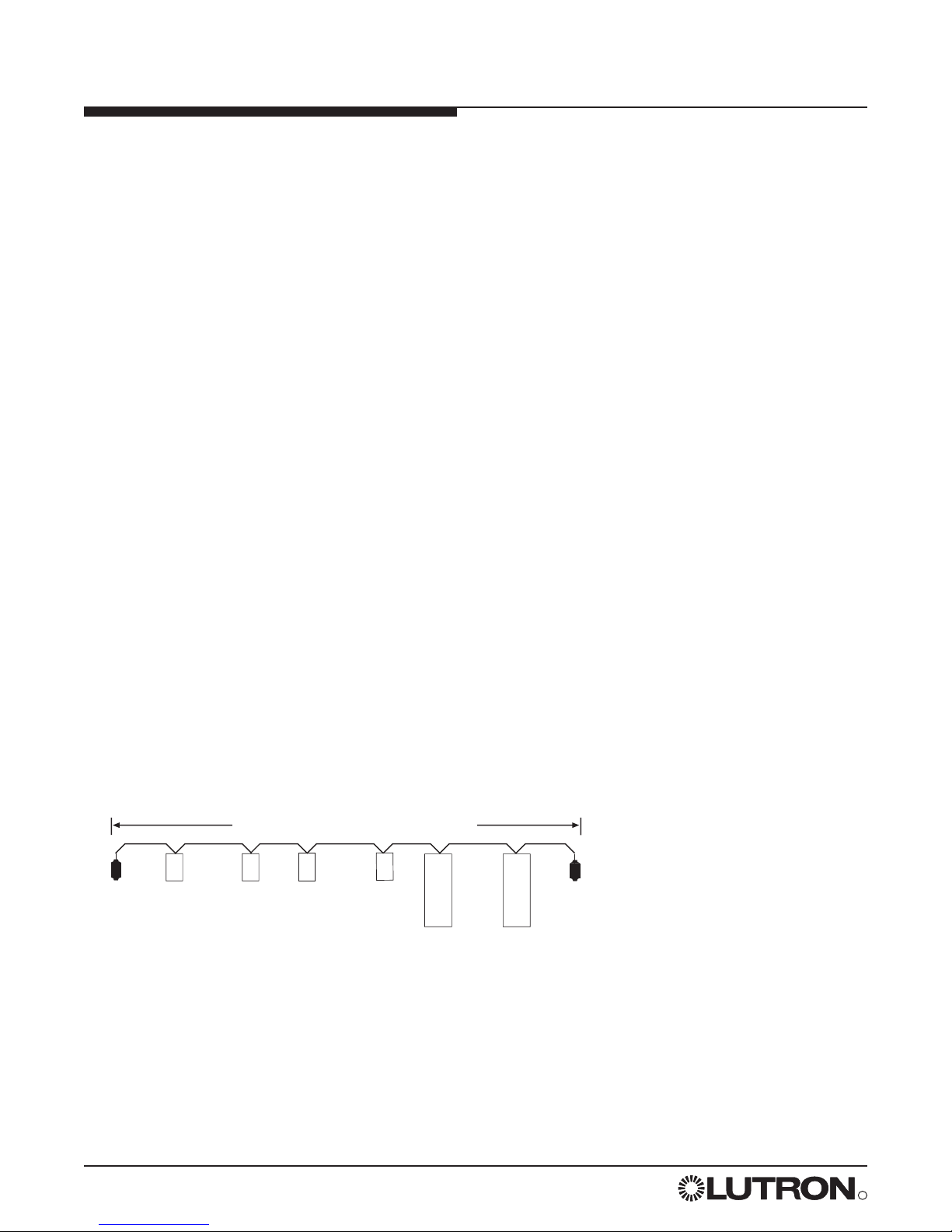
Control Link 2000 ft. (600 m) maximum
LCP128 Panels
Control Stations:
Wallstations, key switches, contact
closure devices, and RS232 devices
System Overview Diagram
LT-1
LT-1
Page 5

R
LCP128
TM Setup and Maintenance Guide 5
Introduction
System Specifications
LCP128 is a lighting control system designed for commercial buildings. It consists of up to 8 dimming panels
and up to 32 control stations. Control stations can be wallstations, key switches, contact closure input and
output devices (OMX-AV), contact closure output devices (OMX-CCO-8), or building management system
interfaces (OMX-RS232). All panels and control stations are connected by a digital communications link. Refer
to the LCP128 Installation Guide for wiring details. Other system specifications are described below.
Time Clock
• 7 weekly schedules.
• Up to 40 holiday schedules.
• Each holiday schedule can be 1-90 days.
• Up to 500 time clock events.
• Maximum of 25 time clock events per day.
• Up to 32 scenes and 1 Off scene.
• With each time clock event or control station input, you can select which circuits turn on or off and, for dimming
circuits, set specific dimming levels.
• Time clock events can occur at a fixed time of day or at a time relative to sunrise or sunset (astronomical).
• Events can be placed on either a weekly schedule (for example, occurring every Monday) or a holiday schedule
(for example, occurring only on January 1).
• Holiday schedules override weekly schedules.
• Time clock events can start and end afterhours mode. Afterhours is an energy saving mode where lights that
are set to be off will automatically, after a period of time, turn themselves off. Afterhours mode can be
temporarily overridden by any control station action. See STEP 5 for more information.
• Time clock events can enable and disable control stations.
Control Station - Wallstation
Wallstation buttons can be individually programmed to:
• Select a scene or custom scene. A scene is a combination of preset lighting levels used to automatically turn
on, off, or dim a circuit or group of circuits. Each time the wallstation button is pressed, the circuits go to the
programmed scene settings.
• Raise or lower circuits. Dimming circuits progressively raise or lower as long as the button is pressed. Circuits
stay at this setting until another event or control station input occurs.
• Toggle circuits on and off. Each press of the button alternates between turning the circuits on and off. If the
circuits are in a mixed state (some on and some off), the lights turn on.
• Turn off with a time delay. When the button is pressed, the circuits turn off after a preset amount of time.
• Enable or disable time clock.
Control Station - Key Switch
• The key switch (NTOMX-KS) can be programmed for clockwise and counterclockwise turns and with the same
functions as a wallstation button.
Control Station - Contact Closure Inputs
Two contact closure inputs are available on each LCP128 controller – more are available by purchasing a Lutron
OMX-AV control station (five inputs per OMX-AV that can be added anywhere on the digital control station link).
• The contact closure inputs can be programmed on the open and/or closure of the contact to perform the same
functions as a wallstation button.
Page 6

R
6 LCP128
TM Setup and Maintenance Guide
Introduction
Control Station - Contact Closure Outputs
Contact closure outputs can be added with either a Lutron OMX-AV control station (five outputs per OMX-AV) or
with a Lutron OMX-CCO-8 (eight outputs per OMX-CCO-8). Either control station can be added anywhere on
the digital control station link.
• Each contact closure may be momentary or maintained.
• Each contact closure output can be assigned to an action that is programmed to a wallstation button, key turn,
contact closure input, time clock event, or emergency state.
Integration through RS232
The LCP128 system can be integrated with a building management system through the Lutron RS232 interface
(OMX-RS232).
Emergency Power Mode
When a LCP128 panel is placed into emergency power mode (loss of normal power), circuits are changed to
emergency settings and remain at those settings until the controller exits emergency power mode (return of
normal power). All control station inputs and time clock events are ignored while in emergency power mode.
Emergency power mode can be activated using:
• Panel to panel emergency sense line. This method requires that the system have at least two panels. The
system must have at least one normal (non-essential) feed panel and at least one emergency (essential) feed
panel. When power to the normal panel is interrupted, the emergency panel(s) will go into emergency mode.
Note that the normal / emergency switches at the bottom of the controllers need to be set correctly.
• The Lutron emergency lighting interface (LUT-ELI-3PH), a UL 924 listed device, senses the normal (nonessential) line voltage on all three phases (3PH) of normal power. When one or more phases of power are lost,
the LUT-ELI-3PH sends a signal to the LCP128 controller. If the LCP128 controller’s normal / emergency switch
is set to emergency, the emergency lighting scene or programmed circuit levels are activated.
For more information on emergency lighting applications, refer to Application Note #106. Available at
www.lutron.com.
Page 7

LCP128 System Start-Up Checklist for Electrical Contractor
Important Note:
To ensure that the LCP128 System is ready for Start-Up, please complete the following checklist.
The LCP128 panel(s) and control station(s) have been mounted in accordance with the installation instructions.
Control stations have been wired to the panel in accordance with installation instructions.
Feed and load wiring to panel have been installed in accordance with the installation instructions.
All load circuits have been activated in bypass mode (bypass jumpers installed) and are correctly and
permanently lamped.
Bypass jumpers have been removed and all circuits activated as default Non-Dim load type.
Load schedule for each panel has been completed.
Correct load type for each circuit has been determined and recorded.
When the above checklist is completed, please fax this sheet along with the completed load schedule
for each panel to Lutron Field Service Scheduling at (610) 282-0298.
Signature: ___________________________ Job Name: _________________________________________
Today’s Date: _________________________ Lutron Job Number: _________________________________
Printed Name: _______________________ Scheduled Startup Date: _____________________________
Phone Number: _______________________ Scheduled Startup Time: _____________________________
Fax Number: _________________________ Job Site Number: ___________________________________
Bill of Material (panels, control stations, etc.):
____________________________________ Qty. ___________
____________________________________ Qty. ___________
____________________________________ Qty. ___________
Lutron Electronics Co., Inc.
7200 Suter Road
Coopersburg, PA 18036-1299
Telephone: 800-523-9466 (Listen to menu for scheduling)
System Start-Up Checklist
R
LCP128
TM Setup and Maintenance Guide 7
Page 8

Page 9
R
LCP128
TM Setup and Maintenance Guide 9
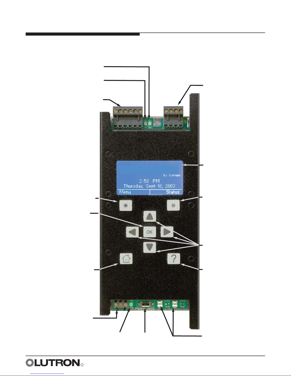
LCP128 Controller Layout
Digital Control Station Link
and Emergency Sense Line
Connector
Panel Contact Closure
Inputs Connector
Digital Link Receive (RX) LED
Digital Link Transmit (TX) LED
24 VAC Power
Input Connector
Normal /
Emergency Switch
Module Control
Harness Connectors
Help Button
Home Button
Navigation Arrows
Right Soft Labeled
Button
LCD Screen
OK Button
Power OK LED
Controller Overview
Left Soft Labeled Button
LCP128TM
Page 10
R
10 LCP128
TM Setup and Maintenance Guide
Main Menu
Overrides
Time Clock Setup
Control Station Setup
Panel CCI Setup
Back
OK
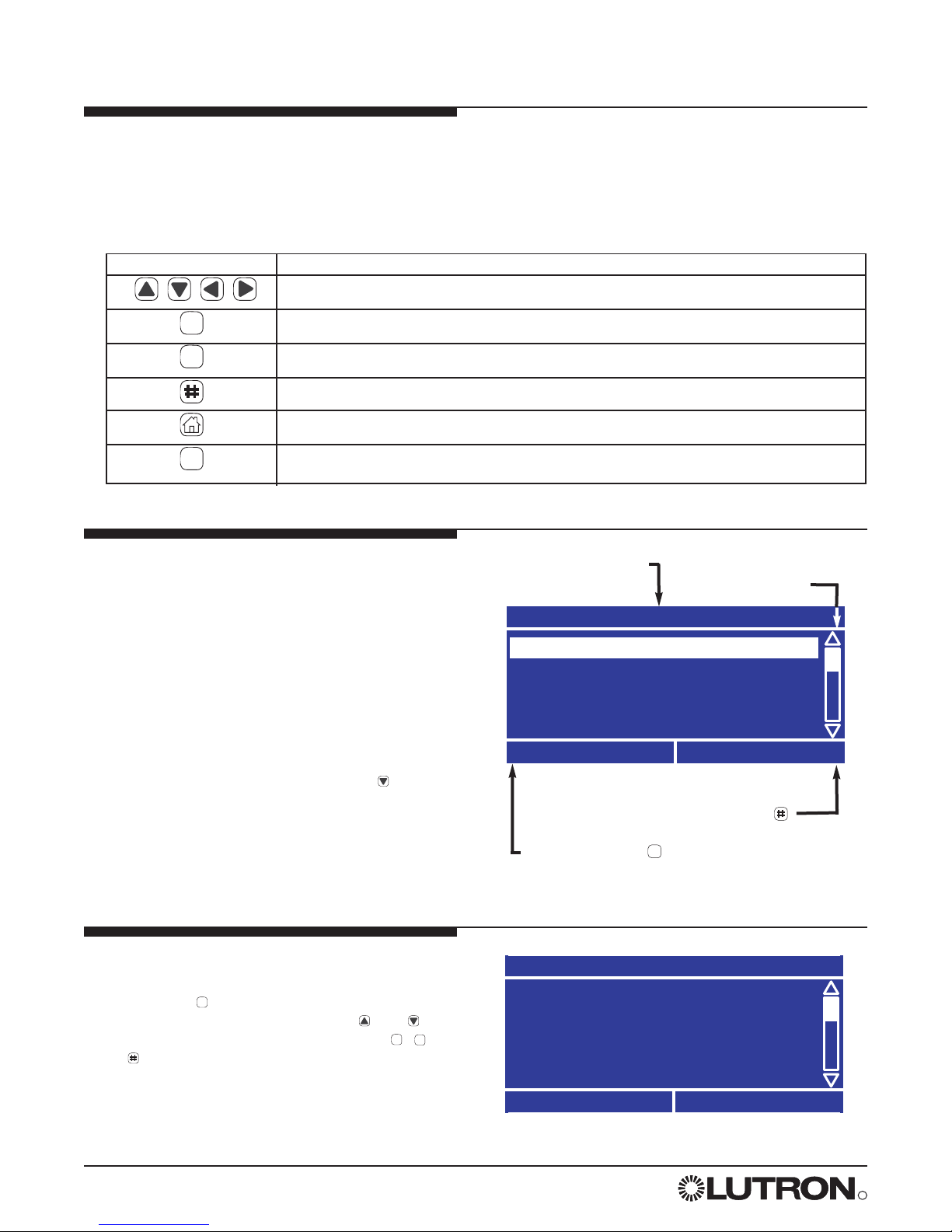
Screen Title
Scroll Bar
Left Soft Label ( )
Right Soft Label ( )
Button Function
Navigate the screen and change highlighted values
Select an item
Left Soft-Labeled – Function defined on screen
Right Soft-Labeled – Function defined on screen
Go to the Home screen
On-Screen Help
Navigation
The LCP128 controller uses certain methods for navigating, selecting, setting values, etc. Please read this
section carefully before using the controller to program your system.
The LCP128 controller has nine buttons below the display. The table below explains their functions.
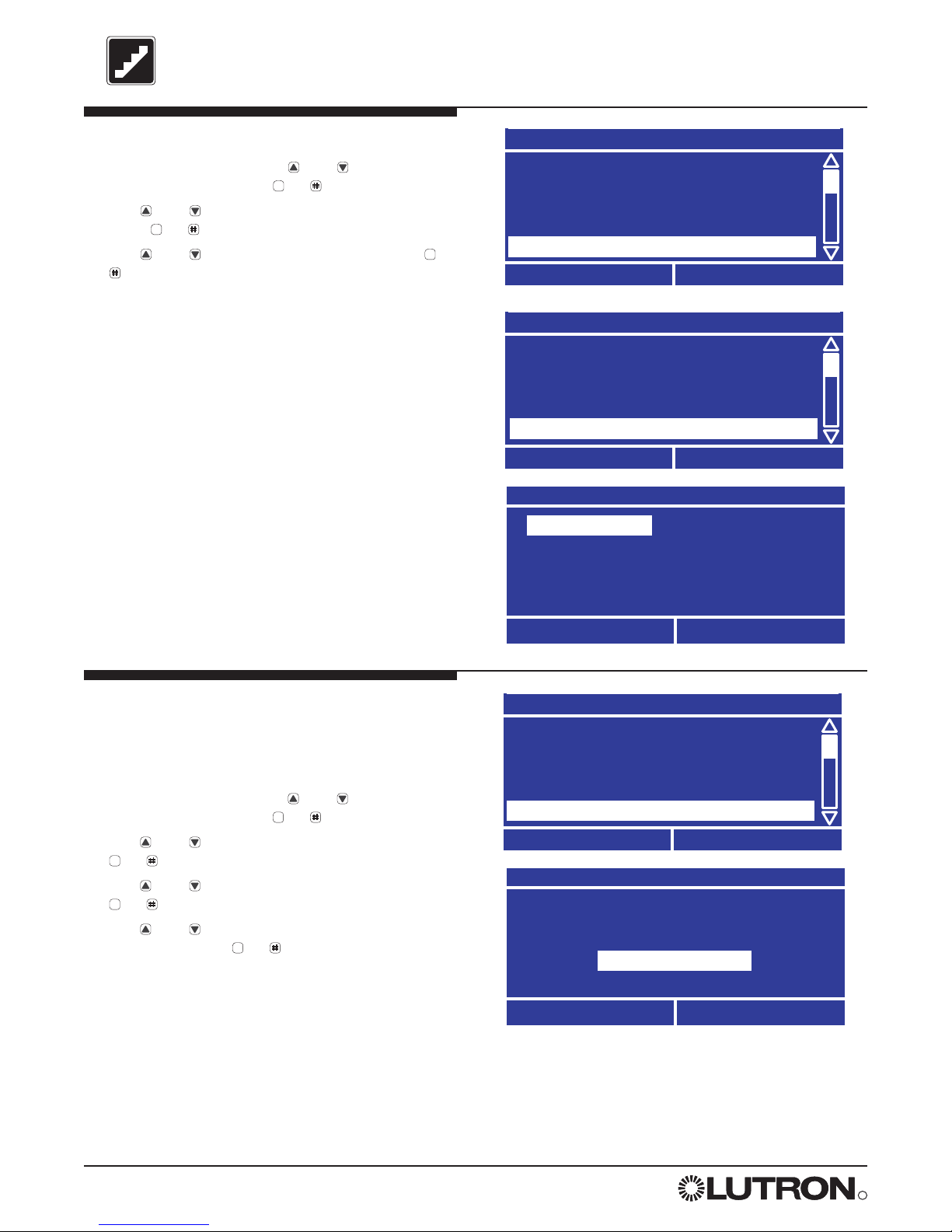
The Screen
All screens on the LCP128 controller have a
similar look with some common elements.
These are:
• A screen title
• Left and right soft button labels
• A scroll bar (only present if more information is
available than will fit on the screen.)
The example shows the Main Menu. The scroll
bar indicates that there is more information in the
menu than fits on the screen. Pressing
repeatedly scrolls through the menu and shows
other choices. The shaded slider on the scroll
bar indicates what portion of the menu is being
displayed.
Help
Help on the current screen is always available by
pressing the button. If more information is
available than fits on the screen, use and
to scroll through the text. Pressing either ,
or returns you to the screen you were on.
Help
The home screen shows the
current date and time. Press *
to go to the Menus, press # to go
to the Status screen.
Back
OK
Controller Overview
OK
*
?
*
?
OK
*
Page 11
Main Menu
Overrides
Time Clock Setup
Control Station Setup
Panel CCI Setup
Back
OK
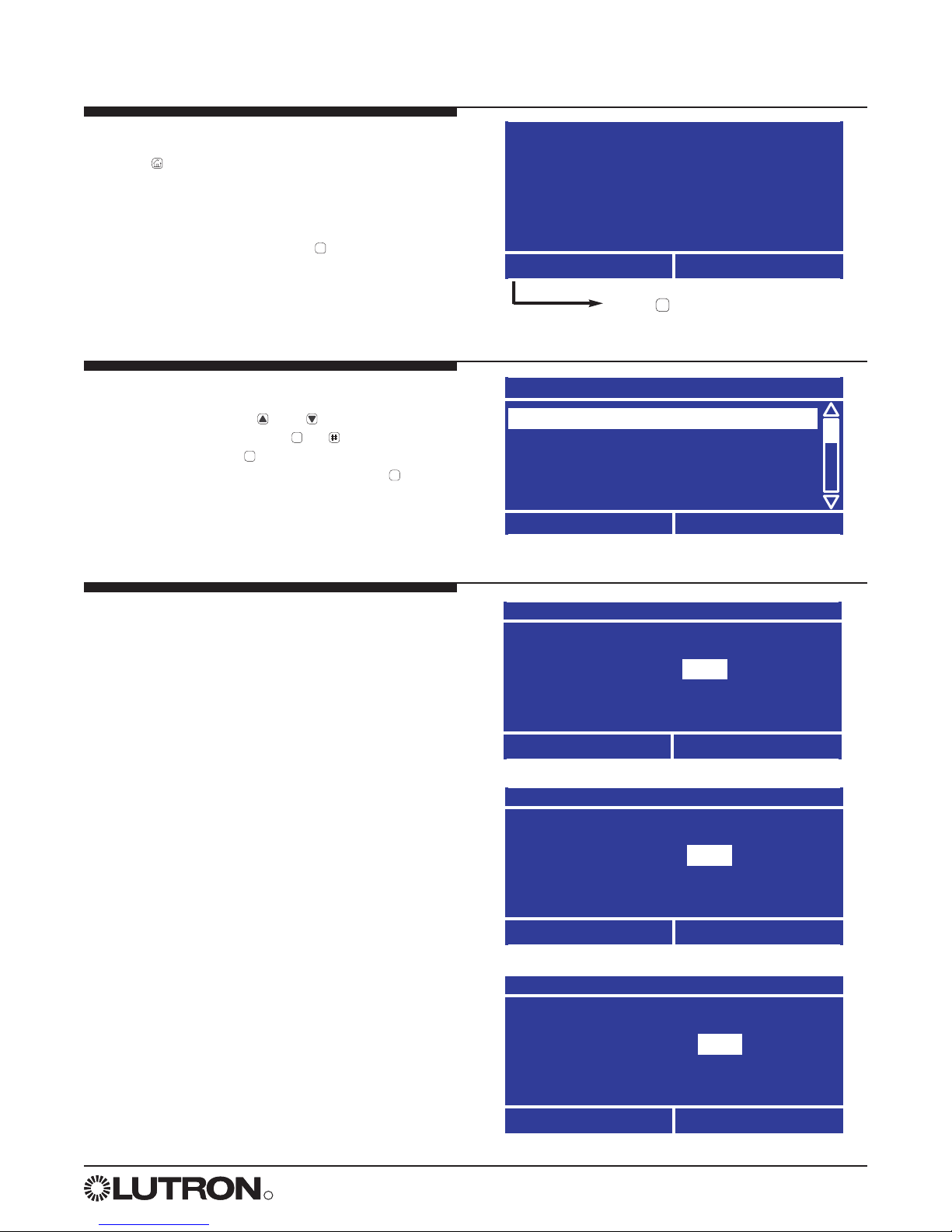
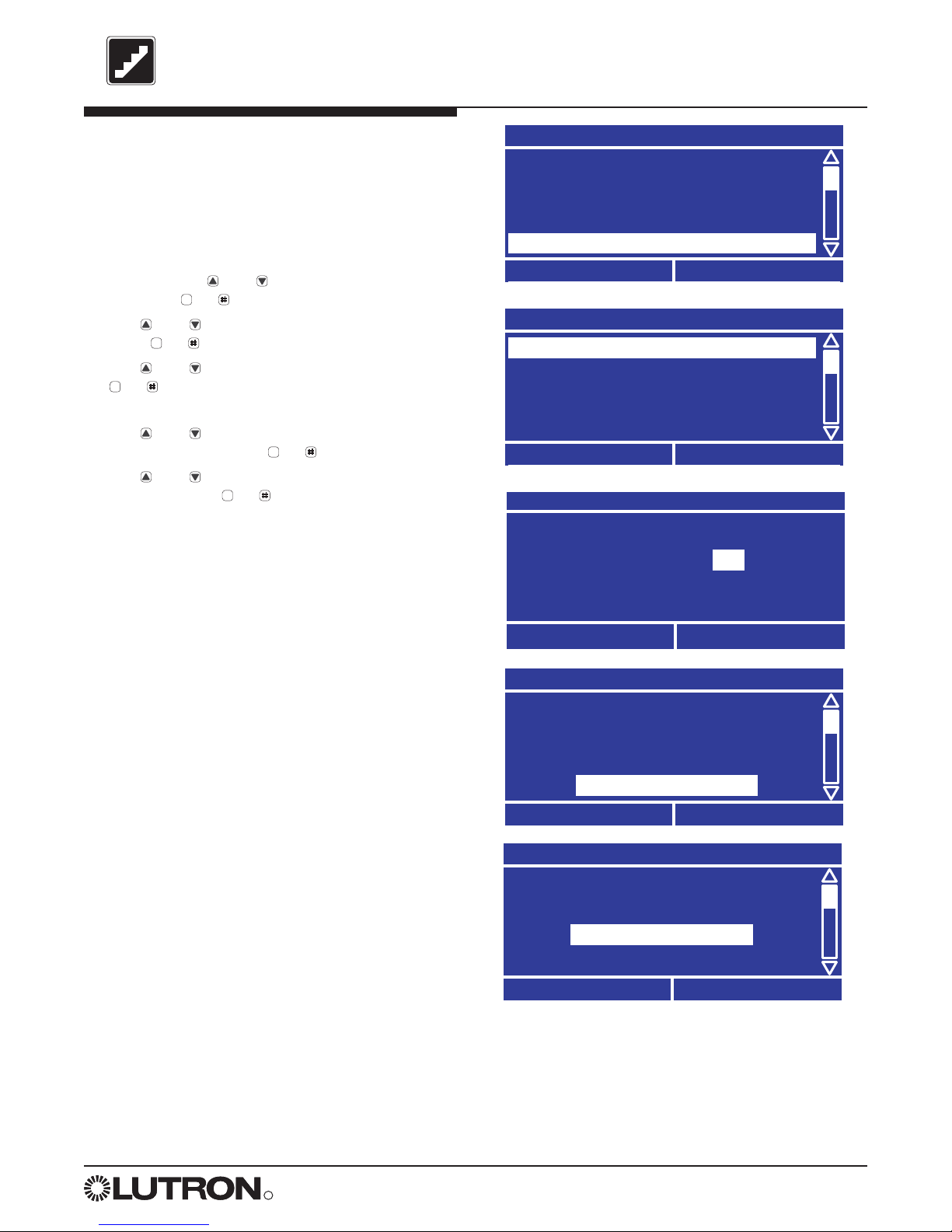
Getting to the Home Screen
Press from any screen to go back to the Home
screen.
Accessing the Main Menu
From the Home screen, press to go to the Main
Menu. If a password has been set, you need to
enter it before continuing (see “Locking and
Unlocking the Controller” in the reference section
later in this guide).
LCP128
TM
by Lutron
8:00 AM
Wednesday, Nov 3, 2004
Menu
Status
Press to Activate the Menu
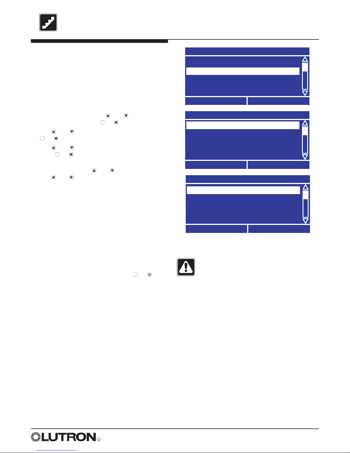
Navigating the Menus
When in a menu, use and to change the
highlighted item and press or (OK) to select
that item. Pressing provides help on that item.
To go back to the previous screen, press (Back).
Entering Data
One or more screens are used to program the
information required for each system feature.
If only one screen is required, the screen has the
soft labeled buttons “Cancel” and “Done”.
If multiple screens are required, the first screen has
the soft labeled buttons “Cancel” and “Next”.
Intermediate screens have the soft labeled buttons
“Previous” and “Next”, and the last screen has the
soft Labeled buttons “Previous” and “Done”.
Note: Data is not stored in the LCP128 system
database until “Done” is selected.
Afterhours Setup
Warn Time: min
Cancel
Next
Afterhours Setup
Flash Count: 0
Previous
Next
Afterhours Setup
Off Delay: min
Previous
Done
01
05
15
R
LCP128
TM Setup and Maintenance Guide 11
Controller Overview
(continued)
*
OK
?
*
*
Page 12
R
12 LCP128
TM Setup and Maintenance Guide
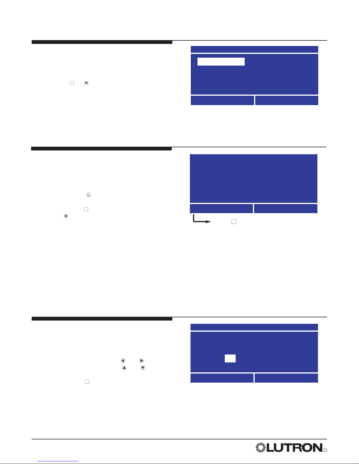
Getting Started - The Home
Screen
• When the controller is first powered or is not used
for 20 minutes, the display shows the Home
screen. Pressing (the Home button) always
takes you back to this screen. From the Home
screen, pressing displays the Main Menu and
pressing displays the Panel Status screen.
• The Home screen shows the current day, date and
time set on the controller. If either of these are
incorrect, refer to STEP 2 to set the date, time, and
location.
• The backlight on the LCD turns off after 25 minutes
of no activity. Pressing any button on the control
turns the backlight on and displays the Home
screen.
Unlocking the Controller
If the controller has been locked (see “Locking the
Controller” in the referenced function section) you
are prompted to enter the password before the
Main Menu is activated. Press and to select
the digit to change. Then press and to
change each digit. When you have entered the
password, press .
If you forget the password, contact Lutron technical
support at 1 (800) 523-9466 to unlock the
controller.
LCP128
TM
by Lutron
8:00 AM
Wednesday, Nov 3, 2004
Menu
Status
Press to Activate the Menu
Unlock Panel
Enter Password
0 0 0 0
Cancel
OK
0
Controller Overview
(continued)
Language Select Screen
When the controller is first powered, you are
prompted to choose a language for the screens.
Use the navigation arrows to select a language,
then press or (Done).
Choose Language
English
Francais
Espanol
Italiano
Done
Deutsch
Nederlands
Portugues
OK
*
*
OK
Page 13
R
LCP128
TM Setup and Maintenance Guide 13
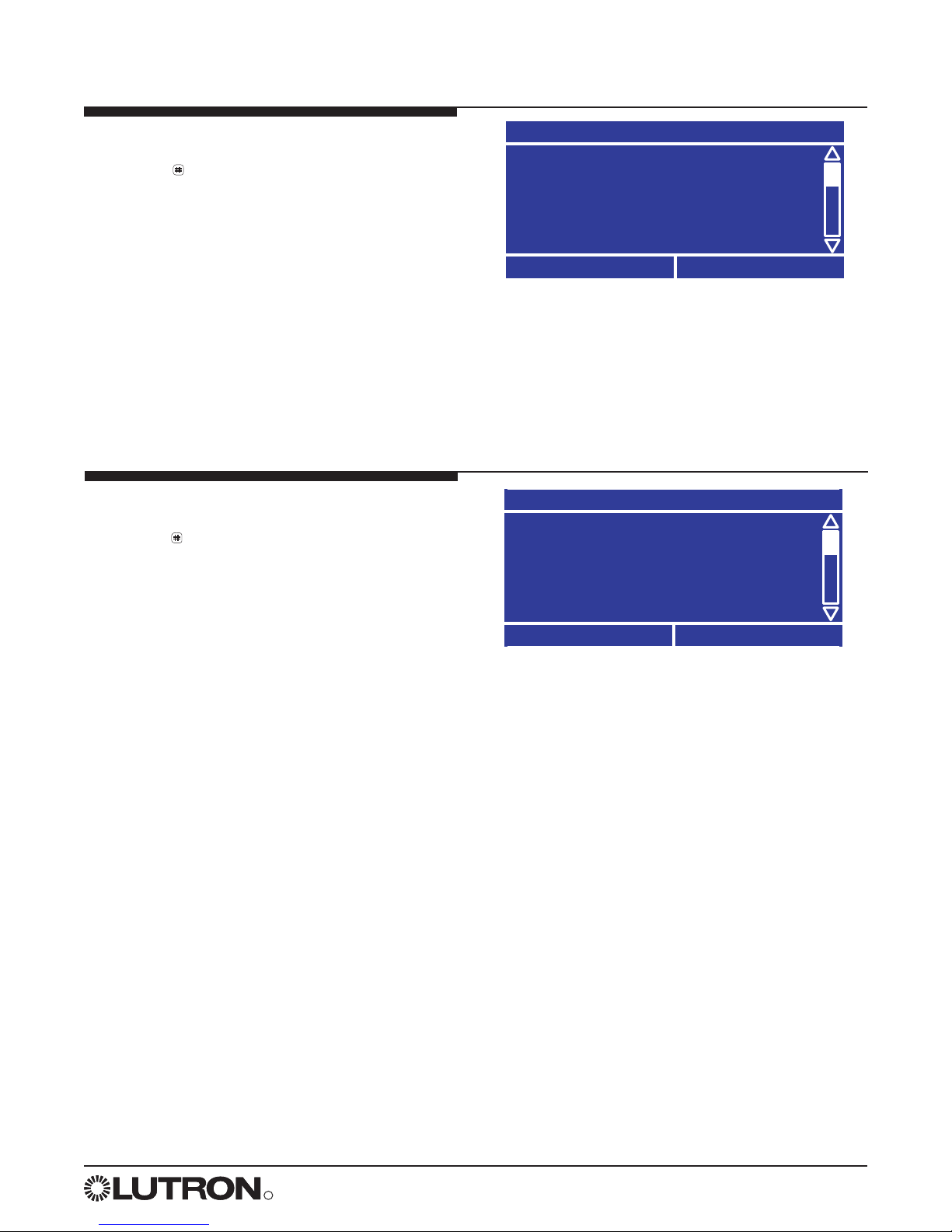
The Panel Status Screen
Pressing from the Home screen displays the
Panel Status screen. The Panel Status screen
shows:
• Your location.
• Sunrise and sunset times for the current system
date (note that the time, date, and location must be
configured correctly).
• Whether time clock events are enabled or disabled.
• Whether control stations are enabled or disabled.
Panel Status
Philadelphia, Pennsylvania
Today’s Sunrise: 05:59AM
Today’s Sunset: 6:07PM
Time Clock : Enabled
Back
Link Detail
The Wallstation Status Screen
Pressing from the Panel Status screen displays
the Wallstation Status screen. The Wallstation
Status screen shows:
• If the station is present and is recognized, the
control is labeled by its type (for example,
“seeTouch”).
• If a station is not present, it is labeled as “No
Station”. This could also indicate a control station
address conflict.
• If the unit is present and is not a control that is
known to the system, the control is labeled as
“???”. This could also indicate a control station
address conflict.
Wall Station Status
A01 - No Station
A02 - seeTouch
A03 - NT/KS/FOMX
A03 - ???
Back
OK
Controller Overview
(continued)
Page 14

R
14 LCP128TM Setup and Maintenance Guide
Step by Step Programming Instructions
Overview
Programming your LCP128 system is done in seven steps.
1. Panel Configuration
This step selects a language for the controller LCD and configures the load setup. For multiple panel systems,
this step also assigns panel addresses and configures the number of circuits in each panel.
2. Time, Date, and Location
Required if the time clock will be used. This step shows how to set the clock.
3. Scene Modification
Required if changes to the default scene settings are needed.
4. Control Stations
Required if there is a remote wallstation, key switch, contact closure device, and/or RS232 device. This step is
performed to configure their function.
5. Time Clock Events
Required if the time clock will be used. This step is used to automatically dim or turn circuits on/off at either a
specific time of day or at a time relative to sunrise or sunset.
6. Panel Contact Closure Inputs
Required if the panel contact closure inputs are used. This step defines what each input will do.
7. Emergency Power Mode
Required if emergency lighting is needed when normal power is lost. Control station inputs and time clock
events are ignored while in emergency power mode. This step defines if the panel has emergency circuits and
how to configure the emergency lighting.
The following pages explain how to perform each of the programming steps.
Page 15
R
LCP128
TM Setup and Maintenance Guide 15
Panel
Address 1
12
Circuits
System
Circuits
1-12
Panel
Address 2
24
Circuits
System
Circuits
13-36
Panel
Address 3
16
Circuits
System
Circuits
37-52
STEP 1
Panel Configuration
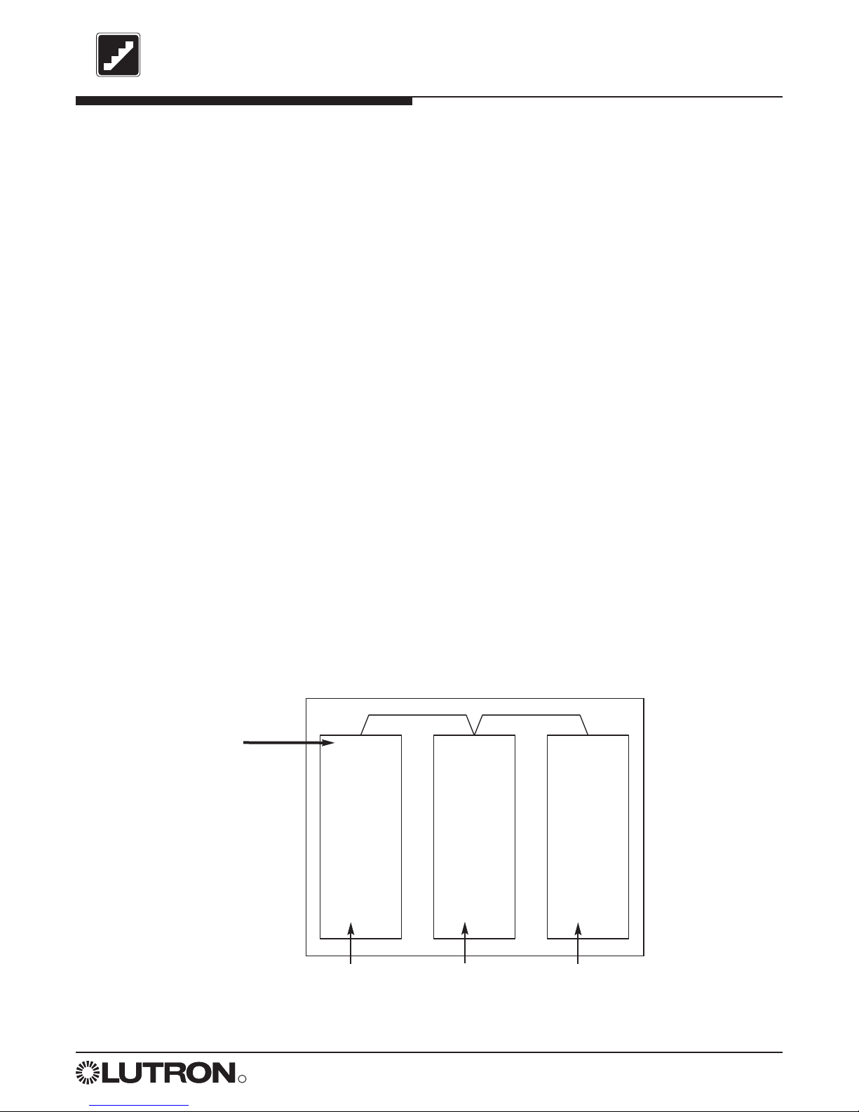
To program a LCP128 panel, you need to:
• Choose a language for the controller LCD.
• Set the panel configuration, including:
• Panel address
• First circuit number in the panel
• Number of circuits in the panel
Each circuit in the system is identified by a system circuit number. This number will be used to identify the
circuit for programming purposes. For example, if Panel 1 has 12 circuits, the first circuit in Panel 2 will be
circuit 13 on the LCP128 controller. The figure below shows a sample system.
Note: If your system has only one panel, you do not need to set the panel configuration. The panel address,
first system circuit number, and number of circuits are preprogrammed. However, for multi-panel systems,
you must set the panel configuration from the master panel (address 1) and then from each remote panel.
• Configure the load setup, including:
• Module type setup
• System size
• Load type
• High end trim
• Low end trim
All system programming (covered in programming STEPS 2-7) is performed at panel address 1. In a multi-
panel system, panel address 1 becomes the master programming panel and all other panels are remote panels.
Remote panels have limited menu options and functionality.
Before proceeding with STEP 1, complete the Panel, Module Type, Load Type, and Control Station
Tables located at the back of this guide.
Master Panel:
All system
programming
must take place
at this panel
First circuit in
this panel
First circuit in
this panel
First circuit in
this panel
Page 16
R
16 LCP128TM Setup and Maintenance Guide
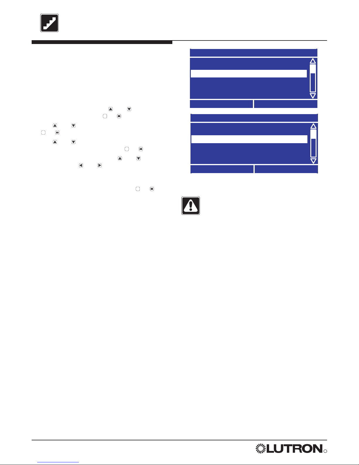
STEP 1 (continued)
Choose a Language
A. From the Main Menu use and to highlight
Panel Setup and press or (OK).
B. Use and to highlight Choose Language and
press or (OK).
C. Use and to set the Language and press or
(Done). The default is English.
Panel Setup
Choose Language
Load Setup
Emergency Setup
Afterhours Setup
Back
OK
B.
Main Menu
Control Station Setup
Panel CCI Setup
Panel Setup
Scene Setup
Back
OK
A.
Choose Language
Cancel
Done
C.
Set System Size
You can set the system size so that controller
screens display only the circuits used by your
system. The default system size is 128 circuits.
A. From the Main Menu use and to highlight
Panel Setup and press or (OK).
B. Use and to highlight Load Setup and press
or (OK).
C. Use and to highlight System Size and press
or (OK).
D. Use and to set the total number of system
circuits and press or (Done).
System Size
How many circuits
are in this system?
Cancel
Done
52
D.
Load Setup
System Size
Chicago Setup
Low End Trim Setup
High End Trim Setup
Back
OK
C.
English
Francais
Espanol
Italiano
Deutsch
Nederlands
Portugues
OK
OK
OK
OK
OK
OK
OK
Page 17
R
LCP128
TM Setup and Maintenance Guide 17
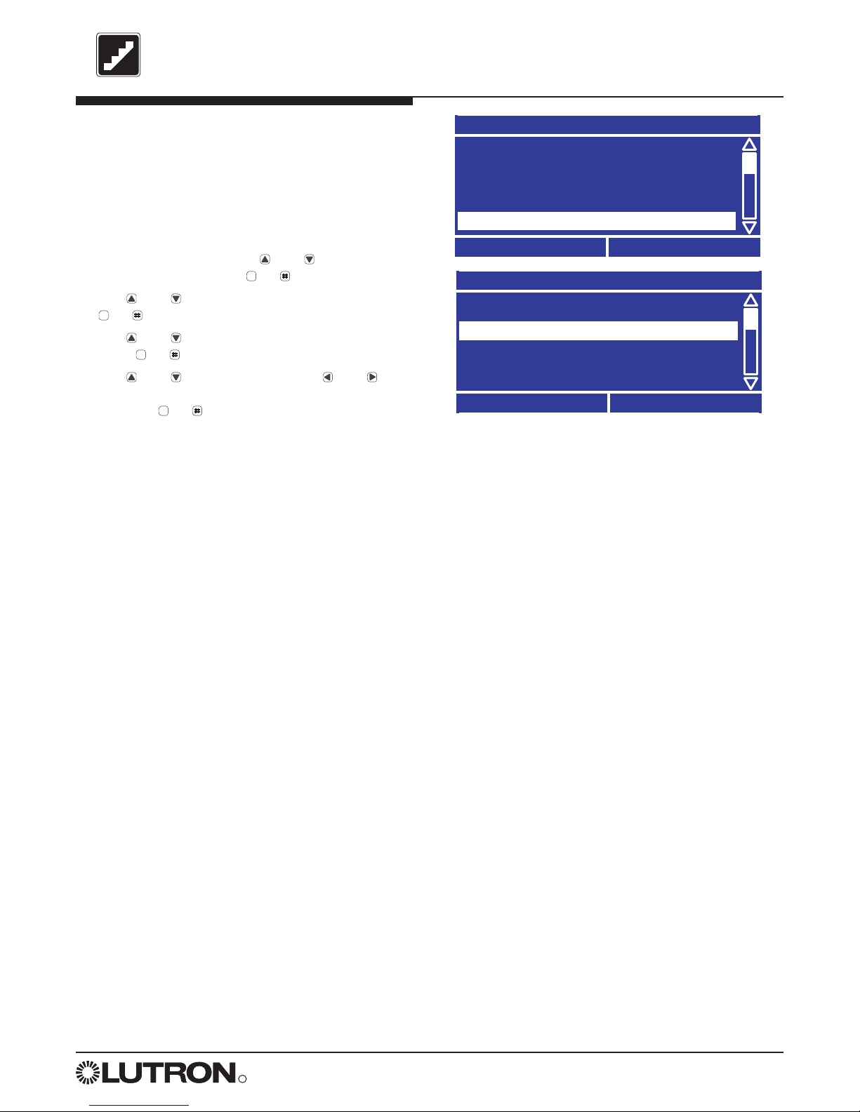
STEP 1 (continued)
Set Panel Configuration Multi-Panel Systems Only
For multi-panel systems, you must set the address
and number of circuits for each panel, beginning
with the master panel.
A. From the Main Menu at the master panel
controller, use and to highlight Panel Setup
and press or (OK).
B. Use and to highlight Panel Addressing and
press or (OK).
C. Use and to set the Panel Address and press
or (Next).
Master panel address = 01
D. Use and to set the first system circuit number
in the panel, and press or (Next).
E. Use and to set the number of circuits in the
panel and press or (Done) to update the
database.
F. Repeat this procedure at each remote panel to set
the panel address and number of circuits.
Panel 2 address = 02
Panel 3 address = 03
Etc.
Panel Setup
Panel Addressing
Load Setup
Emergency Setup
Afterhours Setup
Back
OK
Panel Addressing
Panel Address:
Master Programming Panel
Cancel
Next
01
B.
C.
Circuit Offset Setup
What is the first
system circuit number
in this panel?
Previous
Next
D.
001
Circuit Offset Setup
How many circuits
are in this panel?
Previous
Done
E.
36
Main Menu
Control Station Setup
Panel CCI Setup
Panel Setupetup
Scene Setup
Back
OK
A.
OK
OK
OK
OK
OK
Page 18
R
18 LCP128TM Setup and Maintenance Guide
STEP 1 (continued)
Module Type Setup
Your LCP128 system contains modules configured
with one or more outputs (circuits). The module
types are set by the model numbers of the panels
in the system. Complete the Module Type Table at
the back of this guide and then program the
module types for your system. The factory default
module type is X (4 Switches).
A. From the Main Menu use and to highlight
Panel Setup and press or (OK).
B. Use and to highlight Load Setup and press
or (OK).
C. Use and to highlight Module Type Setup and
press or (OK).
D. The Module Type Setup screen lists all the circuits.
To program a module, use and to select the
first circuit number in the module and and to
set the module type.
Module type options include:
X: Four-Circuit Switching (Relay) Module (XP)
S: One-output (circuit) Dimming Module (1U)
D: Two-output (circuit) Dimming Module (2U)
Q: Four-output (circuit) Dimming Module (4U)
E: Four-output (circuit) Electronic Low Voltage
Dimming Module (4E)
M: Four-output (circuit) Motor Module (4M)
F: Four-output (circuit) Quiet Fan Speed Module
(4FSQ)
Notes:
As you set each module type, the appropriate
circuit numbers are automatically assigned to the
module.
If you set the system size earlier in STEP 1, the
Module Type Setup screen lists only the circuits
used in your system.
E. When all the module types are set press or
(Done).
Load Setup
Module Type Setup
Chicago Setup
Low End Trim Setup
System Size
Back
OK
C.
Module Type Setup
001-004 - E:4 ELV
005-006 - D:2 dimmers
007-010 - X:4 switches
Cancel
Done
D.
011-014 - Q:4 dimmers
Panel Setup
Load Setup
Panel Addressing
Emergency Setup
Afterhours Setup
Back
OK
B.
OK
OK
OK
OK
Page 19
R
LCP128
TM Setup and Maintenance Guide 19
STEP 1 (continued)
Load Type Setup
Complete the Load Type Table at the back of this
guide and then program the load types for your
system circuits. The factory default load type for
each circuit is Non-Dim.
Note: If you are unsure of the load type for a
particular circuit, set the load type to Non-Dim
until the correct setting is determined.
A. From the Main Menu use and to highlight
Panel Setup and press or (OK).
B. Use and to highlight Load Setup and press
or (OK).
C. Use and to highlight Load Type Setup and
press or (OK).
D. The Load Type Setup screen lists all the circuits.
For each circuit, use and to select the circuit
and and to select the load type.
Load type options depend on the module type
assigned to the circuit:
Switching: Non-dim, DSI, 0-10V, DALI, PWM
Dimming: Incandescent, MLV (Magnetic Low
Voltage), Tu-Wire (ballasts), Neon, ELV (Electronic
Low Voltage), Non-dim, DSI, 0-10V, DALI, PWM
Motors: Motor
Fans: Fan
NNoottee::
Switching or dimming modules controlling
DSI, 0-10V, DALI, or PWM load types require
TVM(s).
E. When all the load types are set press or
(Done).
Load Type setup is now complete and all
settings are saved in the event of a power
failure.
Panel Setup
Load Setup
Panel Addressing
Emergency Setup
Afterhours Setup
Back
OK
B.
Load Setup
Load Type Setup
High End Trim Setup
Low End Trim Setup
Chicago Setup
Back
OK
C.
Load Type Setup
001 Dim - Incandescent
002 Dim - ELV
003 Relay - Non-Dim
Cancel
Done
D.
004 Dim - Tu-Wire
Caution! Failure to correctly assign load types
may damage loads, especially certain
electronic transformers, electronic ballasts,
and motors. Verify with the transformer or
ballast manufacturer that the product can be
dimmed with phase control dimming before
setting to any load type other than Non-Dim.
OK
OK
OK
OK
Page 20
R
20 LCP128TM Setup and Maintenance Guide
STEP 1 (continued)
High/Low End Trim Setup
High and low end trim settings limit the maximum
and minimum output of a dimming circuit. Levels
are set automatically when the load type is
assigned. You should change the high or low end
trim for a circuit only if the default setting needs to
be adjusted.
A. From the Main Menu use and to highlight
Panel Setup and press or (OK).
B. Use and to highlight Load Setup and press
or (OK).
C. Use and to highlight High End Trim Setup or
Low End Trim Setup and press or (OK).
D. For each dimming circuit, use and to select
the circuit and and to set the trim level. Nondimming, motor, and fan circuits are set to NA (not
any).
E. When all the trim levels are set press or
(Done).
Load Setup
High End Trim Setup
Load Type Setup
Low End Trim Setup
Chicago Setup
Back
OK
C.
High End Trim Setup
001 Dim - 90%
002 Dim - 95%
003 Relay - NA
Cancel
Done
D.
All Circuits -
Caution! Do not reduce the low end trim on a
fluorescent load type. This will decrease lamp
life and may damage ballasts.
OK
OK
OK
OK
Page 21
R
LCP128
TM Setup and Maintenance Guide 21
STEP 1 (continued)
Chicago Setup
This function is used to meet electrical installation
codes in the city of Chicago, IL (USA). This setting
limits how low a light level can be, including the
levels in the “off” scene. This setting can be
changed to a value from 10% to 60%, in 1%
increments.
A. From the Main Menu use and to highlight
Panel Setup and press or (OK).
B. Use and to highlight Load Setup and press
or (OK).
C. Use and to highlight Chicago Setup and
press or (OK).
D. Use and to select a circuit and and to
set the Chicago limit. When all the circuit limits are
set press or (Done).
Load Setup
Chicago Setup
Load Type Setup
Low End Trim Setup
High End Trim Setup
Back
OK
C.
Chicago Setup
Cancel
Done
D.
001 Dim - OFF
002 Dim - 10%
003 Relay - ON
All Circuits -
OK
OK
OK
OK
Page 22

R
22 LCP128TM Setup and Maintenance Guide
STEP 2
Time Clock Configuration
The LCP128 system can be programmed to initiate scenes and other actions automatically at either a specific
time of day or at a time relative to sunrise or sunset. It is important to configure the time clock as needed for
your location.
Time clock configuration includes:
• Selecting a time format (12 or 24 hour).
• Setting the time.
• Setting the date.
• Setting the location, either by country/city or longitude/latitude.
• Adjusting sunrise and sunset times to accommodate special circumstances.
• Selecting whether to use daylight savings time and, if so, what rules to use.
Page 23

R
LCP128
TM Setup and Maintenance Guide 23
STEP 2 (continued)
Time Format
A. From the Main Menu use and to highlight
Time Clock Setup and press or (OK).
B. Use and to highlight Setup Clock and press
or (OK).
C. Use and to highlight Time Format and press
or (OK).
D. Use and to specify 24 Hr. or AM / PM
(12 Hr). Press or (Done) to save changes.
Time
A. From the Setup Clock menu use and to
highlight Time and press or (OK).
B. Use and to change the current time. Use
and to alternate between hours and minutes.
C. Press or (Done) to save changes.
Date
A. From the Setup Clock menu use and to
highlight Date and press or (OK).
B. Use and to change the current date. Use
and to change between month, day, and year.
The first 2 digits are the month, the middle 2 are
the day, and the last 4 are the year.
C. Press or (Done) to save changes.
Time
: 35 AM
HH : MM
Cancel
Done
Date
/ 16 / 2004
MM / DD / YYYY
Cancel
Done
06
11
Setup Clock
Date
Location
Daylight Savings Time
Time Format
Back
OK
C.
B.
B.
Time Format
Specify by:
Cancel
Done
24 Hr.
D.
OK
OK
OK
OK
OK
OK
OK
OK
Page 24

R
24 LCP128TM Setup and Maintenance Guide
STEP 2 (continued)
Location
Note: Location must be set if using time clock
events relative to sunrise or sunset.
A. From the Setup Clock menu use and to
highlight Location and press or (OK).
B. Use and to select whether you want to set
the location by country and city (recommended) or
by latitude and longitude (if there are no nearby
cities listed). Press or (OK) when done.
Set Location Method
Country, City
Latitude, Longitude
Back
OK
B.
Set Time Zone
GMT -5:00 Eastern Time
GMT -4:00 Atlantic Time
GMT -3:30 Newfoundland
GMT -3:00 Brasilia
Previous
Next
Set Country
USA
Austria
Belgium
China
Cancel
Next
Specify Latitude, Longitude
Latitude Longitude
9 . 6 N 075 . 1 W
(DEGREES) (DEGREES)
Cancel
Next
3
C.
C.
D.
If Setting by Country and City
C. Use and to select the Country then press
or (Next).
In the USA, use and to select the State then
press or (Next).
D. Use and to select the City then press or
(Next).
If Setting by Latitude and Longitude
C. Use and to select the digit and use and
to set the latitude and longitude of your location in
degrees and press or (Next).
D. Use and to select the time zone for this
location and press or (Next). Values are listed
as an offset from Greenwich Mean Time.
Example: If your location is 39 degrees 36 minutes
north, enter 39.6N degrees. The minutes are
converted to a decimal of a degree by dividing by
60.
OK
OK
OK
OK
OK
OK
OK
Page 25

R
LCP128
TM Setup and Maintenance Guide 25
STEP 2 (continued)
Location (continued)
Adjusting Sunrise and Sunset
E. If needed, use this feature to shift your location’s
sunrise and sunset times by a fixed amount. This
can be useful if there is a geographic feature (such
as a mountain) that offsets the sunrise or sunset
time for your location by a fixed amount. This can
also be used to shift all time clock events that are
relative to sunrise and sunset after they have been
programmed.
If no offset is required, leave the offsets at 0:00
(default). Press or (Done) to save changes.
Note: Do not use this function to compensate for
daylight savings time. For procedures on how to
program daylight savings time settings, refer to
the next page.
Adjust Sunrise / Sunset
Sunrise Sunset
+ 00 : 00 + 00 : 00
Previous
Done
+
E.
OK
Page 26

R
26 LCP128TM Setup and Maintenance Guide
STEP 2 (continued)
Daylight Savings Time
Use this feature to set whether or not your location
uses daylight savings time. If it does, you can
configure when it starts and ends. When daylight
savings time is used, the time will change
automatically.
A. From the Setup Clock menu use and to
highlight Daylight Saving Time and press or
(OK).
B. Use and to set whether or not your location
uses daylight savings time, then press or
(Next).
C. If your location follows the United States rules for
daylight savings time (Starts on the 1st Sunday in
April, ends on the last Sunday in October at 2 AM,
offset by 1 hour) then select United States.
Otherwise select Other. Press or (Done) to
save changes.
D. If you select Other, you are prompted to enter the
rules. The default rules are set based on your
location. You will need to know:
• The start month, week, and day.
• The end month, week, and day.
• The number of minutes to adjust for daylight
savings time, up to 120 minutes.
Daylight Savings
Does this location
use daylight savings?
Yes
Cancel
Next
Daylight Savings
Current Setting
United States
Previous
Done
B.
C.
Setup Clock
Date
Location
Time
Daylight Saving Time
Back
OK
A.
OK
OK
OK
Page 27

R
LCP128
TM Setup and Maintenance Guide 27
STEP 3
Scene Modification
Scenes are stored lighting levels for each circuit in your system. Scenes can be used to create different lighting
effects using a programmed mix of dimming and switching settings.
The LCP128 system comes with 32 pre-configured scenes and 1 Off scene (see the table below for default
scene settings). As you program your system, you can assign these scenes to time clock events. For example,
at 6 PM each evening certain dimming circuit levels rise and additional circuits turn on. You can also assign
scenes to control station inputs (wallstation buttons, key switches, and contact closures). This way, any time a
button is pressed, key is turned, or contact closure is made, the system activates the desired scene.
In STEP 3, you can modify the preconfigured scenes as needed to create your own specific lighting
environments.
Note: In STEPS 4 and 5, you can also create additional custom scenes associated with a specific timeclock
event or control station input.
Scene
Default Settings
for Dimming Circuits
Default Settings
for Switching Circuits
Off OFF OFF
1 100% ON
2 75% ON
3 50% ON
4 25% ON
5 to 32 100% ON
Page 28

R
28 LCP128TM Setup and Maintenance Guide
STEP 3 (continued)
Modify Scenes
A. From the Main Menu use and to highlight
Scene Setup and press or (OK).
B. The Scene Modification screen lists the
preconfigured scenes stored in your system. Use
and to choose the scene you want to modify
and press or (Next).
C. The system lists each circuit and its current setting
for this scene. Use and to select a circuit and
and to change the setting for that circuit. To
simultaneously change all circuits, select All
Circuits and use and to change the setting.
Note: The All Circuits function enables you to
simultaneously adjust the percentage for all
dimming circuits or to turn all circuits off or on.
Scene circuit settings depend on the circuit type:
Switching: ON, OFF, --- (unaffected)
Dimming: OFF, 1 - 100%, --- (unaffected)
Motors: Open, Close, Stop, Jog Up, Jog Down,
--- (unaffected)
Fans: Low, Medium, Medium-High, High,
--- (unaffected)
Note: The --- (unaffected) setting means that the
circuit is not affected by this scene.
When you are finished modifying the scene press
or (Next).
D. The Select CCO Address screen is displayed only if
control station devices with contact closure outputs
(OMX-AV or OMX-CCO-8) have been entered into
the system (see STEP 4).
Use and to select the output to be associated
with the scene being programmed. The letter “A”
followed by a two digit number at the beginning of
each line refers to the the address of the device.
Use and to change the setting for that output:
maintained open, maintained close, momentary
pulse, or --- (unaffected).
When the outputs are programmed press or
(Done).
Example: A01 CCO2 is address1 contact closure
output 2.
E. For dimming circuits affected by the scene, use
and to set a fade time and press or (Next).
F. For a combination of dimming and switching
circuits, use and to set whether switches
react at Start of Fade or End of Fade. Then press
or (Done).
Scene Modification
Off Scene
Scene 01
Scene 02
Scene 03
Cancel
Next
B.
Scene 02
All Circuits -
001 Dim - 50%
002 Dim - 75%
003 Relay - ON
Previous
Next
C.
Select CCO Address
A01 CCO1 -Maintained Open
A01 CCO2 - ---
A01 CCO3 - --A01 CCO4 - ---
Previous
Next
D.
Scene 02 Fade Time
Fade Time:
20 sec
Previous
Next
E.
Scene 02 Switches
When do
switches react?
Start of Fade
Previous
Done
F.
OK
OK
OK
OK
OK
OK
Page 29

R
LCP128
TM Setup and Maintenance Guide 29
STEP 4
Control Stations
Control stations are connected to the LCP128 panel via the digital control link. Control stations can be
wallstations (with various numbers of buttons), key switches (NTOMX-KS), contact closure input and output
devices (OMX-AV), contact closure output devices (OMX-CCO-8), or OMX-RS232 interfaces. Each control
station must be assigned a unique address. Addressing may be found in either the LCP128 Installation Guide
or installation guides for the individual devices. To set the address, refer to the instructions for each device.
Every wallstation button, key switch, or contact closure input can be assigned one of the following functions:
• Scene - A scene consists of a specified light level and fade time. Each time the button, key switch, or contact
closure input is activated, the assigned circuits go to the programmed scene. A scene can also be used to
control contact closure outputs.
• Custom Scene - A custom scene is a scene assigned to and programmed for a specific button press, key
switch turn, or contact closure input. A custom scene may be recalled only by that single action to which it is
assigned.
• Lower Circuits - Assigned dimming circuits are progressively lowered as long as input is received from the
control station (for example, the button is held down, key is turned, contact closure is maintained). Circuits stay
at this setting until another event or control station input occurs.
• Raise Circuits - Assigned dimming circuits are progressively raised as long as input is received from the control
station (for example, the button is held down, key is turned, contact closure is maintained). Circuits stay at this
setting until another event or control station input occurs.
• Toggle - Each time the button, key switch, or contact closure input is activated, the assigned circuits toggle
between on and off. If the assigned circuits are in a mixed state (some on and some off), the circuits turn on.
• Delay To Off - Each time the button, key switch, or contact closure input is activated, the assigned circuit(s) turn
off after the preset amount of time (1 - 90 minutes).
• Enable Time Clock - Enable the function of the time clock.
• Disable Time Clock - Disable the function of the time clock.
Before proceeding with STEP 4, complete the Control Station Table at the back of this guide. Record
what each input (button, key switch, or contact closure) on each control station should do.
Note: In STEP 4, you will configure contact closure inputs wired to a Lutron OMX-AV control station.
Contact closure inputs wired directly to a panel are configured later in STEP 6.
Page 30

R
30 LCP128TM Setup and Maintenance Guide
STEP 4 (continued)
Configure the Wallstations
A. From the Main Menu use and to highlight
Control Station Setup and press or (OK).
B. Use and to choose the Address of the
wallstation you would like to configure and press
or (Next).
Note: The wallstation Address selected must
match the Address switch setting on the
wallstation.
C. Use and to set the Type to Wall Station and
press or (Next).
D. Use and to select whether the station has
Permanent Raise and Lower Buttons and press
or (Next).
E. Use and to set the Number of buttons and
press or (Next).
Note: Do not count raise/lower buttons.
F. Use and to select the Button you want to
program and press or (Next).
G. Use and to select the type of Action for this
button: Lower Circuits, Raise Circuits, Scene,
Custom Scene, Enable Time Clock, Disable
Time Clock, Delay to Off, Toggle, or No Action
and press or (Next).
Refer to the following pages to program each type
of action.
Control Station Setup
Address 01
Address 02
Address 03
Address 04
Cancel
Next
Address 03 Setup
Number of Buttons:
Previous
Next
03
Address 01 Setup
Button 01
Button 02
Button 03
Previous
Next
B.
E.
F.
Address 03 Button 01
Action:
Previous
Next
Lower Circuits
G.
Address 03 Setup
Type:
Previous
Next
Wall Station
C.
OK
OK
OK
OK
OK
OK
OK
Page 31

R
LCP128
TM Setup and Maintenance Guide 31
STEP 4 (continued)
Select Circuits
All Circuits - ---
001 Dim - 10%
002 Dim - 20%
003 Relay - ON
Previous
Next
Configure the Wallstations
(continued)
If Selecting a Scene Action
H. In step G, if you selected Scene, use and to
select the scene and press or (Done).
H.
Select CCO Address
A01 CCO1 - Maintained Open
A01 CCO2 - ---
A01 CCO3 - --A01 CCO4 - ---
Previous
Done
I.
Select Scene
Scene:
02
Previous
Done
H.
Custom Scene Fade Time
Fade Time:
20 sec
Previous
Next
J.
If Selecting a Custom Scene Action
H. In step G, if you selected Custom Scene, the
Select Circuits screen lists all the circuits. Use
and to select a circuit and and to change
the setting for that circuit. Or to simultaneously
change all circuits, select All Circuits and use
and to change the setting.
Note: The All Circuits function enables you to
simultaneously adjust the percentage for all
dimming circuits or to turn all circuits off or on.
Circuit settings depend on the circuit type:
Switching: ON, OFF, --- (unaffected)
Dimming: OFF, 1 - 100%, --- (unaffected)
Motors: Open, Close, Stop, Jog Up, Jog Down
Fans: Low, Medium, Medium-High, High
Note: The --- (unaffected) setting means the
circuit is not affected by this scene.
When the circuits are programmed for this custom
scene press or (Next).
I. The Select CCO Address screen is displayed only if
control station devices with contact closure outputs
(OMX-AV or OMX-CCO-8) have been entered into
the system.
Use and to select the output to be associated
with the button being programmed. Use and
to change the setting for that output: maintained
open, maintained close, momentary pulse, or
--- (unaffected). When the outputs are
programmed for this custom scene, press or
(Done).
J. For dimming circuits affected by the custom scene,
use and to set the Fade Time and press
or .
K. For a combination of dimming and switching
circuits, use and to set when the switches
react (Start of Fade or End of Fade). Then press
or .
Custom Scene Fade Time
When do
switches react?
Start of Fade
Previous
Done
K.
Address
number
Contact closure
output number
OK
OK
OK
OK
OK
Page 32

R
32 LCP128TM Setup and Maintenance Guide
STEP 4 (continued)
Configure the Wallstations
(continued)
If Selecting a Delay to Off Action
H. In step G, if you selected Delay to Off, use and
to set the Time to Off and press or .
I. The Assign Circuits screen lists all the circuits.
Unassigned circuit numbers have hash lines going
through them. Move the cursor to a circuit number
and press to toggle between Assigned and
Unassigned (dashed). All circuits can be toggled
by selecting ALL Circuits and pressing . When
the circuits are programmed press .
J. For dimming circuits affected by the action, use
and to set the Fade Time and press or .
K. For a combination of dimming and switching
circuits, use and to set when the switches
react (Start of Fade or End of Fade). Then press
or .
Set Delay Time
Time to Off:
10 min
Previous
Next
H.
Assign Circuits
PRESS OK TO SELECT CIRCUIT
ALL Circuits
001 002 003 004
005 006 007 008
Previous
Done
I.
If Selecting a Lower Circuits, Raise
Circuits, or Toggle Action
H. In step G, if you selected Lower Circuits, Raise
Circuits, or Toggle, the Assign Circuits screen lists
all the circuits. Unassigned circuits are presented as
numbers with hash lines going through them.
Move the cursor to a circuit number and press to
toggle between Assigned and Unassigned
(dashed). All circuits can be toggled by selecting
ALL Circuits and pressing . When the circuits
are programmed press .
I. For dimming circuits affected by the action, use
and to set the Fade Time.
J. For a combination of dimming and switching
circuits, use and to set when the switches
react (Start of Fade or End of Fade). Then press
or .
Assign Circuits
PRESS OK TO SELECT CIRCUIT
ALL Circuits
001 002 003 004
005 006 007 008
Previous
Done
001
H.
001
OK
OK
OK
OK
OK
OK
OK
OK
Page 33

R
LCP128
TM Setup and Maintenance Guide 33
STEP 4 (continued)
Configure Key Switch
(NTOMX-KS)
Lutron’s NTOMX-KS key switch control station can
be programmed to initiate an action for a clockwise
and counter-clockwise turn.
A. From the Main Menu use and to highlight
Control Station Setup and press or (OK).
B. Use and to highlight the address of the
NTOMX-KS you would like to configure and press
or (Next).
C. Use and to change control type to
Key Switch and press or (Next).
D. Use and to highlight which direction turn to
program and press or (Next). Each key
switch can be programmed for a clockwise or
counter-clockwise turn. Both may be programmed.
E. Use and to select the type of Action for this
key turn: Lower Circuits, Raise Circuits, Scene,
Custom Scene, Enable Time Clock, Disable
Time Clock, Delay to Off, Toggle, and No Action
and press or (Next). Refer to the beginning of
STEP 4 for an explanation of the various action
types.
F. Program the Lower Circuits, Raise Circuits,
Scene, Custom Scene, Delay to Off, or Toggle
action using the same screen methods used to
configure a wallstation button. Refer to “Configure
the Wallstations” earlier in STEP 4.
Address 03 Setup
Type:
Key Switch
Previous
Next
Main Menu
Overrides
Time Clock Setup
Control Station Setup
Panel CCI Setup
Back
OK
Control Station Setup
Address 01
Address 02
Address 03
Address 04
Cancel
Next
A.
B.
C.
Address 03 Setup
Clockwise Turn
Counter - Clockwise Turn
Previous
Next
D.
Address 03 Key Switch
Action:
Previous
Next
Scene
F.
OK
OK
OK
OK
OK
Page 34

R
34 LCP128TM Setup and Maintenance Guide
STEP 4 (continued)
Configure Contact Closure
Inputs on OMX-AV
Lutron’s OMX-AV control station can be
programmed to initiate actions for up to five contact
closure inputs.
Note: For contact closure inputs wired directly to
the LCP128 panel, refer to STEP 6.
A. From the Main Menu use and to highlight
Control Station Setup and press or (OK).
B. Use and to highlight the address of the
OMX-AV you would like to configure and press
or (Next).
C. Use and to set the control Type to OMX-AV
and press or (Next).
D. Each OMX-AV provides 5 inputs. Use and to
highlight the Contact Closure Input (CCI) to
program and press or (Next). Or select
No CCI’s if only the contact closure outputs (CCOs)
are being used.
E. Use and to select whether you want define an
action for when the contact opens or when it
closes and press or (Next).
Note: If there should be an action on both, first
set up the Open Action, then follow this
procedure again but choose Closure Action.
F. Use and to select the type of Action for this
CCI: Lower Circuits, Raise Circuits, Scene,
Custom Scene, Enable Time Clock, Disable
Time Clock, Delay to Off, Toggle, and No Action
and press or (Next). Refer to the beginning of
STEP 4 for an explanation of the various action
types.
G. Program the Lower Circuits, Raise Circuits,
Scene, Custom Scene, Delay to Off, or Toggle
action using the same screen methods used to
configure a wallstation button. Refer to “Configure
the Wallstations” earlier in STEP 4.
Address 03 Setup
Type:
OMX-AV
Previous
Next
Address 03 CCI 2 Setup
Open Action
Closure Action
Previous
Next
Main Menu
Overrides
Time Clock Setup
Control Station Setupetup
Panel CCI Setup
Back
OK
Control Station Setup
Address 01
Address 02
Address 03
Address 04
Previous
Next
A.
B.
C.
E.
Address 03 OMX-AV
No CCI’s
CCI 01
CCI 02
CCI 03
Previous
Next
D.
OK
OK
OK
OK
OK
OK
Page 35

R
LCP128
TM Setup and Maintenance Guide 35
STEP 4 (continued)
Integration through RS232
Lutron’s OMX-RS232 control station enables you to
integrate your LCP128 system with a building
management system.
A. From the Main Menu use and to highlight
Control Station Setup and press or (OK).
B. Use and to highlight the address of the
OMX-RS232 you would like to configure and press
or (Next).
C. Use and to change control Type to OMX-
RS232 and press or (Done).
Using the GRAFIK 6000
RS232 protocol.
The OMX-RS232 is packaged and shipped with a
protocol document that details how to execute
each command. Only a subset of the commands
in that document work with the LCP128 system
and they are listed below:
Command LCP128 Function
Fade to Level: Sets a pattern or time
delay to off
Multilevel: Flash circuits
Get Level: Request level
Simulate
Press: Simulate button press
Simulate
Release: Simulate button release
Enable
Control
Stations: Enable control stations
Disable
Control
Stations: Disable control stations
Set Clock: Sets time and date
Time Now: Request time
Astro Times: Request sunrise / sunset times
Date: Request date
Enable
Time clock: Enable time clock
Disable
Time clock: Disable time clock
Address 03 Setup
Type:
OMX-RS232
Previous
Done
Main Menu
Overrides
Time Clock Setup
Control Station Setupetup
Panel CCI Setup
Back
OK
Control Station Setup
Address 01
Address 02
Address 03
Address 04
Previous
Next
A.
B.
C.
OK
OK
OK
Page 36

R
36 LCP128TM Setup and Maintenance Guide
STEP 5
Time Clock Events
Time clock events enable the system to initiate a scene or start/end afterhours mode at either a specific time of
day or at a time relative to sunrise or sunset. 47 schedules are available—one for every day of the week, and 40
holiday schedules. There can be a total of up to 500 events and no more than 25 on any day / holiday. Holiday
schedules always override the weekly schedule.
The options for time clock events are:
• Scene or Custom Scene - The assigned circuits go to the programmed scene/custom scene settings.
• Enable or Disable Controls - Enable or disable the function of control stations.
• Afterhours Start - Starts an energy saving mode that is used to turn lights off at the end of normal hours until
the beginning of the next day. First, a scene or pattern of circuit levels is recalled for the space (Afterhours
Start). Circuits programmed to turn off flash to warn any occupants that they are about to go out (number of
flashes specified by Flash Count). Lights remain on to allow the occupant a chance to press a button to keep
lights on (length of time is programmed as Off Delay). Finally, if a button has not been pressed, lights turn off
automatically at the end of the delay period.
If a button is pressed, occupancy sensor tripped, or another timeclock event occurs while the system is in
Afterhours mode or in Off Delay, lights turn on and remain on for the programmed number of minutes, (Warn
Time) then flash (number specified by Flash Count) and then turn off after the Off Delay.
• Afterhours End - When afterhours ends, the circuits are returned to their programmed state.
Example Scenario for Afterhours:
A. Afterhours start event—afterhours scene is recalled. The circuits that are going to turn off start to flash and off
delay starts counting down.
B. System enters afterhours.
C. Button is pressed to turn lights on.
D. Lights flash notifying they will be turning off soon.
E. Button is pressed to keep lights on.
F. Lights flash notifying they will be turning off soon.
G. Lights turn off.
H. Afterhours end event.
Before proceeding with STEP 5, complete the Time Clock Event Table located at the back of this guide.
Record when each event should occur and what it should do.
Off
Delay
Off
Delay
Off
Delay
Warn Time
Warn Time
Afterhours
A
B
C
D
E
F
G
H
Page 37

R
LCP128
TM Setup and Maintenance Guide 37
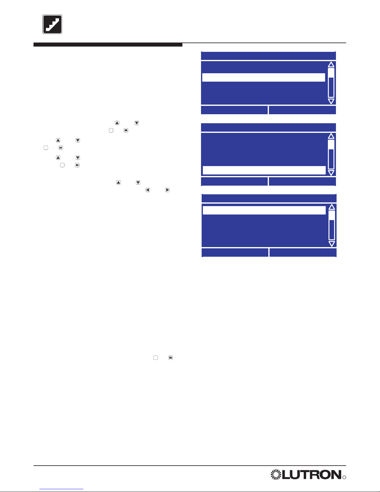
Adding Weekly Events
Weekly events occur each week on a specific day.
A. From the Main Menu use and to highlight
Time Clock Setup and press or (OK).
B. Use and to highlight Add Event and press
or (OK).
C. Use and to highlight Add Weekly Event and
press or (OK).
D. Use and to select the Day to which you
would like to add the event and press or
(Next).
E. Use and to select Fixed Time or at a time
relative to Sunset or Sunrise. Press to adjust
the time or offset. Adjust the time using and
and press or (Next).
F. Use and to select the desired Action for the
event: Scene, Custom Scene, Enable or Disable
Controls, Afterhours Start, or Afterhours End
and press or (Next). Refer to the beginning of
STEP 5 for an explanation of the various action
types.
Note: For Afterhours End, this step is complete.
Event Time
Type Time
Fixed Time
08:00 AM
Previous
Next
Event Time
Type Time
Sunrise +
00:15
HH : MM
Previous
Next
STEP 5 (continued)
Time Clock Setup
Setup Clock
Add Event
Copy Events
View / Modify Events
Back
OK
Fixed
Sunrise
B.
E.
Add Weekly Event
Cancel
Next
D.
Select Day:
Sunday
Add Event
Add Weekly Event
Add Holiday Event
Back
OK
C.
OK
OK
OK
OK
OK
OK
Page 38

R
38 LCP128TM Setup and Maintenance Guide
STEP 5 (continued)
Adding Weekly Events
(continued)
If Selecting a Scene Action
G. In step F, if you selected Scene, use and to
select the desired scene and press or (Done).
To add another event to this same schedule, select
Yes when prompted “Modify More Events?”
Select Scene
Previous
Done
G.
If Selecting an Afterhours Start Action
G. In step F, if you selected After Hours Start, choose
Select Scene or Set Circuit Level. Then press
or (Next).
H. Select the scene or set the circuit levels to be used
for afterhours mode. Then press or (Done).
Refer to the beginning of STEP 5 for a detailed
description of how afterhours mode works.
To add another event to this same schedule, select
Yes when prompted “Modify More Events?”
Note: You will set the afterhours warn time, flash
count, and off delay later in STEP 5.
If Adding a Custom Scene Action
G. In step F, if you selected Custom Scene, set the
circuit settings for the custom scene. Then press
or (Done).
To add another event to this same schedule, select
Yes when prompted “Modify More Events?”
Select Circuits
All Circuits - ---
001 Dim - 10%
002 Dim - 20%
003 Relay - ON
Previous
Done
G.
Scene:
03
Afterhours Setup
Select Scene
Set Circuit Levels
Previous
Next
G.
OK
OK
OK
OK
Page 39

R
LCP128
TM Setup and Maintenance Guide 39
STEP 5 (continued)
Adding Holiday Events
Holiday events occur on a specific date and can
last for 1 to 90 days.
A. From the Main Menu use and to highlight
Time Clock Setup and press or (OK).
B. Use and to highlight Add Event and press
or (OK).
C. Use and to highlight Add Holiday Event and
press or (OK).
D. Use and to select the holiday to which you
would like to add the event and press or
(Next).
To define a new holiday, select New Holiday.
• Enter the start date of the holiday.
• Enter the duration of the holiday. For example,
New Year’s might be defined as starting on
December 31st and lasting 2 days (Dec 31 and
Jan 1).
E. Use and to select Fixed Time or at a time
relative to Sunset or Sunrise. Press to adjust
the time or offset. Adjust the time using and
and press or (Next).
F. Use and to select the desired Action for the
event: Scene, Custom Scene, Enable or Disable
Controls, Afterhours Start, or Afterhours End
and press or (Next). Refer to the beginning of
STEP 5 for an explanation of the various action
types.
Program the action using the same method as for a
weekly event. Refer to “Adding Weekly Events”
earlier in STEP 5.
Note: For Afterhours End, this step is complete.
Add Holiday Event
Select Holiday:
Add New Holiday
Cancel
Next
Holiday Start Date
12 / 31
MM / DD
Previous
Next
Holiday Duration
Number of Days:
Previous
Next
02
Add Event
Add Weekly Event
Add Holiday Event
Back
OK
C.
D.
OK
OK
OK
OK
OK
OK
Page 40

R
40 LCP128TM Setup and Maintenance Guide
STEP 5 (continued)
Copying Events
A. From the Main Menu use and to highlight
Time Clock Setup and press or (OK).
B. Use and to highlight Copy Events and press
or (OK).
C. Use and to highlight Copy Weekly Event or
Copy Holiday Event and press or (OK).
D. Use and to select the day of the week or
holiday you would like to copy from and press or
(Next).
E. Use and to select the event you would like to
copy and press or (Next). If you would like to
copy all events programmed for this day or holiday,
select All Events.
F. Use and to select the day or holiday you
would like to paste to and press or (Done).
Holidays appear after the weekdays in the list. To
add a new holiday, select New Holiday at the end
of the list and then modify the existing holiday’s
information to save it as a new holiday
To paste the event to another day or holiday, select
Yes when prompted to “Paste Again?”.
Select Event to Copy
Sun - All Events
Sun - Fixed 08:00 AM
Sun - Sunrise +0:15
Sun - Sunset -0:30
Previous
Next
Paste Event To
Day:
Previous
Done
Deleting Events
A. From the Main Menu use and to highlight
Time Clock Setup and press .
B. Use and to highlight Delete Event.
C. Use and to highlight Delete Weekly Event or
Delete Holiday Event.
D. Use and to select the day of the week or
holiday you would like to delete from.
E. Use and to select the event you would like to
delete. If you would like to delete all events for that
schedule, select All Events.
F. You are asked to confirm deleting the event(s).
Press Yes to delete, otherwise press No.
To delete another event from that day or holiday,
select Ye s when prompted to “Delete Another?”.
Select Event to Delete
Sun - All Events
Sun - Fixed 08:00 AM
Sun - Sunrise +0:15
Sun - Sunset -0:30
Previous
Done
Time Clock Setup
Add Events
Copy Events
View / Modify Event
Delete Event
Back
OK
Friday
E.
F.
B.
E.
OK
OK
OK
OK
OK
OK
OK
Page 41

R
LCP128
TM Setup and Maintenance Guide 41
STEP 5 (continued)
Afterhours Setup
A. From the Main Menu use and to highlight
Panel Setup and press or (OK).
B. Use and to highlight Afterhours Setup and
press or (OK).
C. Use and to set a Warn Time, from 1 to 180
minutes and press or (Next).
D. Use and to set the Flash Count, from 1 to 15
flashes and press or (Next).
E. Use and to set an Off Delay, from 1 to 180
minutes and press or (Done).
Notes:
To add an afterhours start action, refer to “Adding
Weekly Events” earlier in STEP 5.
120 minutes is the maximum allowable off delay
in California Title 24.
Panel Setup
Load Setup
Emergency Setup
Afterhours Setup
Choose Language
Back
OK
Main Menu
Control Station Setup
Panel CCI Setup
Scene Setup
Panel Setup
Back
OK
Viewing / Modifying Events
A. From the Main Menu use and to highlight
Time Clock Setup and press or (OK).
B. Use and to highlight View/Modify Event and
press or (OK).
C. Use and to highlight Modify Weekly Event or
Modify Holiday Event and press or (OK).
D. Use and to select the day or holiday you
would like to view or modify and press or
(Next).
E. Use and to select the event you would like to
view or modify and press or (Next).
F. You now have the opportunity to modify this event.
For procedures, refer to “Adding Weekly Events” or
“Adding Holiday Events” earlier in STEP 5.
Select Event to Modify
Sun - All Events
Sun - Fixed 08:00 AM
Sun - Sunrise +0:15
Sun - Sunset -0:30
Previous
Next
Time Clock Setup
Setup Clock
Add Events
Copy Events
View / Modify Events
Back
OK
View / Modify Event
Modify Weekly Event
Modify Holiday Event
Back
OK
B.
C.
E.
A.
B.
OK
OK
OK
OK
OK
OK
OK
OK
OK
OK
Page 42

R
42 LCP128TM Setup and Maintenance Guide
STEP 6
Panel Contact Closure Inputs
The LCP128 controller has two contact closure inputs (see illustration below). Separate actions can be defined
for the opening and closing of the contact. The choices are:
• Scene or Custom Scene - Each time the contact closure input is activated, the assigned circuits go to the
programmed scene. A scene can also be used to control contact closure outputs.
• Enable or Disable Time Clock - Enable or disable the function of the time clock.
• Toggle - Each time the contact closure input is activated, the assigned circuits toggle between on and off. If the
assigned circuits are in a mixed state (some on and some off), the circuits turn on.
• Delay To Off - Each time the contact closure input is activated, the assigned circuit(s) turn off after the preset
amount of time (1 - 90 minutes).
Before proceeding with STEP 6, complete the Control Station Table located at the back of this guide.
Record how each local contact closure should function. Designate them: Panel 1 CCI 1 Opening,
Panel 1 CCI 1 Closing, Panel 1 CCI 2 Opening, Panel 1 CCI 2 Closing, and continue for Panel 2 through
Panel 8 as required.
LCP128 controller Top
Panel CCI Terminal Markings
1: 15VDC or 24VDC CCI 1
2: Common CCI 1
3: 15VDC or 24VDC CCI 2
4: Common CCI 2
1 2 3 4
Page 43

R
LCP128
TM Setup and Maintenance Guide 43
Assign Circuits
PRESS OK TO SELECT CIRCUIT
ALL Circuits
001 002 003 004
005 006 007 008
Previous
Done
STEP 6 (continued)
Configure Panel Contact
Closure Inputs
Note: For contact closure inputs wired to a
Lutron OMX-AV control station, refer to STEP 4.
A. From the Main Menu use and to highlight
Panel CCI Setup and press or (OK).
B. Use and to choose the contact closure input
you want to configure and press or (OK).
C. Use and to select whether you want to define
an action for when the contact Opens or Closes
and press or (Next).
D. Use and to choose the type of Action for the
CCI: Scene, Custom Scene, Enable or Disable
Time Clock, Delay to Off, Toggle, or No Action.
Program the desired action using the following
procedures.
Panel 1 CCI 1
Open Action
Closure Action
Previous
Next
001
E.
C.
Panel CCI Setup
Panel 1 CCI 1
Panel 1 CCI 2
Panel 2 CCI 1
Panel 2 CCI 2
Back
OK
B.
If Selecting a Toggle Action
E. In step D, if you selected Toggle, the Assign
Circuits screen lists all the circuits. Unassigned
circuits are presented as numbers with hash lines
going through them. Move the cursor to a circuit
number and press to toggle between Assigned
and Unassigned (dashed). All circuits can be
toggled by selecting ALL Circuits and pressing .
When the circuits are programmed press .
F. For dimming circuits affected by the action, use
and to set the Fade Time.
G. For a combination of dimming and switching
circuits, use and to set when the switches
react (Start of Fade or End of Fade). Then press
or .
OK
OK
OK
OK
OK
OK
Page 44

R
44 LCP128TM Setup and Maintenance Guide
STEP 6 (continued)
Configure Contact Closure
Inputs (continued)
If Selecting a Scene Action
E. In step D, if you selected Scene, use and to
select the scene and press or (Done).
Select CCO Address
A01 CCO1 - Maintained Open
A01 CCO2 - ---
A01 CCO3 - --A01 CCO4 - ---
Previous
Done
F.
Custom Scene Fade Time
Fade Time:
20 sec
Previous
Next
G.
Custom Scene Fade Time
When do
switches react?
Start of Fade
Previous
Done
H.
Select Scene
Scene:
05
Previous
Done
E.
If Selecting a Custom Scene Action
E. In step D, if you selected Custom Scene, the
Select Circuits screen lists all the circuits. Use
and to select a circuit and and to change
the setting for that circuit. Or to simultaneously
change all circuits, select All Circuits and use
and to change the setting.
Note: The All Circuits function enables you to
simultaneously adjust the percentage for all
dimming circuits or to turn all circuits off or on.
Circuit settings depend on the circuit type:
Switching: ON, OFF, --- (unaffected)
Dimming: OFF, 1 - 100%, --- (unaffected)
Motors: Raise, Lower, Stop, Jog Up, Jog Down
Fans: Low, Medium, Medium-High, High
Note: The --- (unaffected) setting means the
circuit is not affected by this scene.
When the circuits are programmed for this custom
scene press or (Next).
F. The Select CCO Address screen is displayed only if
control station devices with contact closure outputs
(OMX-AV or OMX-CCO-8) have been entered into
the system.
Use and to select the output to be associated
with the scene being programmed. Use and
to change the setting for that output: maintained
open, maintained close, momentary pulse, or
--- (unaffected). When the outputs are
programmed for this custom scene, press or
(Done).
G. For dimming circuits affected by the custom scene,
use and to set the Fade Time and press
or .
H. For a combination of dimming and switching
circuits, use and to set when the switches
react (Start of Fade or End of Fade). Then press
or .
Select Circuits
All Circuits - ---
001 Dim - 10%
002 Dim - 20%
003 Relay - ON
Previous
Next
E.
Address
number
Contact closure
output number
OK
OK
OK
OK
OK
Page 45

R
LCP128
TM Setup and Maintenance Guide 45
STEP 6 (continued)
Configure Contact Closure
Inputs (continued)
If Selecting a Delay to Off Action
E. In step D, if you selected Delay to Off, use
and to set the Time to Off and press or
(Next).
F..The Assign Circuits screen lists all the circuits.
Unassigned circuits are presented as numbers with
hash lines going through them. Move the cursor to
a circuit number and press to toggle between
Assigned and Unassigned (dashed). All circuits
can be toggled by selecting ALL Circuits and
pressing . When the circuits are programmed
press .
G. For dimming circuits affected by the action, use
and to set the Fade Time and press or .
H. For a combination of dimming and switching
circuits, use and to set when the switches
react (Start of Fade or End of Fade). Then press
or .
Set Delay Time
Time to Off:
05 min
E.
Assign Circuits
PRESS OK TO SELECT CIRCUIT
ALL Circuits
001 002 003 004
005 006 007 008
Previous
Done
001
F.
Previous
Next
OK
OK
OK
OK
OK
Page 46

R
46 LCP128TM Setup and Maintenance Guide
STEP 7
Emergency Power Mode
Perform this step only if you want to configure an emergency power mode when normal power is lost. All
control station inputs and time clock events are ignored while in emergency power mode. This step defines if
the panel has emergency circuits and, if so, how to configure the emergency settings. For multi-panel systems,
emergency settings are configured on the master panel and each remote panel.
• Identify panels fed by normal (non-essential) power. Move their emergency switches to the left position, see
illustration below.
• For all the emergency (essential) lighting panels, move the emergency switches to the right position, see
illustration below.
• The essential and non-essential panels must be connected by a sense line wired to terminal 5 on the link
connector on the LCP128 controller, see illustration below. (For wiring details see the LCP128 Installation Guide).
In this configuration, the emergency (essential) lighting panel will “sense” the normal panels’ power. When
normal power is lost, the emergency panel will go to the emergency settings (factory set to all circuits On).
Notes:
• If UL 924 certification is required, the Lutron Emergency Lighting Interface (LUT-ELI-3PH) may be used to
meet code. The LUT-ELI-3PH senses the normal (non-essential) line voltage on all three phases (3PH) of
normal power. When one or more phases of power are lost, the LUT-ELI-3PH will send a signal to
terminal 5 on the LCP128 controller(s). When the emergency switch is set to the right position
(essential), the emergency lighting settings will be recalled. The LUT-ELI-3PH can be used with one or
multiple panel systems.
• Loss of normal power can be simulated by turning off all connected normal (non-essential) panels’ control
breaker.
• When the emergency switch is in its center position (as shipped), terminal 5 on the panel does not
respond to the emergency.
Left Position
(Non-Essential)
Normal
Right Position
(Essential)
Emergency
Use Terminal 5 to
connect a sense line
between emergency and
normal panels, or
between the LUT-ELI-3PH
and one or more
emergency panels. A
#18 AWG wire is
recommended for the
sense line
Center Position
(No response to Emergency)
Three-position Emergency Switch is located at
the bottom of the LCP128 controller.
LCP128 controller top
1234 5
D
Page 47

R
LCP128
TM Setup and Maintenance Guide 47
STEP 7 (continued)
Configuring the Emergency
Setting Levels
A. From the Main Menu use and to highlight
Panel Setup and press or (OK).
B. Use and to highlight Emergency Setup and
press or (OK).
C. When asked if the panel has emergency
functionality, use and to select Yes and press
or (Next).
D. The Emergency Setup screen lists all the circuits
and their default emergency settings. Use and
to select a circuit and and to change the
setting for that circuit. To simultaneously change all
circuits, select All Circuits and use and to
change the setting.
Note: The All Circuits function enables you to
simultaneously adjust the percentage for all
dimming circuits or to turn all circuits off and on.
Circuit settings depend on the circuit type:
Switching: ON, OFF, --- (unaffected)
Dimming: OFF, 1 - 100%, --- (unaffected)
Motors: Open, Close, Stop, Jog Up, Jog Down
Fans: Low, Medium, Medium-High, High
Note: The --- (unaffected) setting means the
circuit is not affected by emergency mode.
When the circuits are programmed for emergency
mode, press or (Next).
E. The Select CCO Address screen is displayed only if
control station devices with contact closure outputs
(OMX-AV or OMX-CCO-8) have been entered into
the system. Use and to scroll through the list
to select the output to be associated with the
button being programmed. Use and to
change the setting for that output between:
maintained open, momentary open, momentary
close, maintained close or --- (unaffected). When
the outputs are programmed press or (Done)
to update the database.
F. For multi-panel systems, repeat the procedure to
program the emergency settings at each remote
panel.
Emergency Setup
All Circuits - 100%
001 Dim - 100%
002 Dim - 100%
003 Relay - ON
Previous
Next
Panel Setup
Panel Addressing
Emergency Setup
Afterhours Setup
Back
OK
B.
D.
Select CCO Address
A01 CCO1 - Maintained Open
A01 CCO2 - ---
A01 CCO3 - --A01 CCO4 - ---
Previous
Done
E.
Load Setup
Emergency Setup
have emergency
Yes
Cancel
Next
C.
Does this panel
Address
number
Contact closure
output number
OK
OK
OK
OK
OK
Page 48

R
48 LCP128
TM Setup and Maintenance Guide
Lutron is very interested in your comments on this Guide and on its
products. Please call (800) 523-9466 with any feedback or
suggestions. Thank you for your help.
Your LCP128 System is now
programmed and ready to use.
Keep this guide with the system. It should include the completed
Control Location, Panel, Module Type, Load Type, and Control
Station Tables.
The rest of this guide is REFERENCE MATERIAL.
Important:
Page 49

R
LCP128
TM Setup and Maintenance Guide 49
Overrides
Overview
From time to time, you may need to temporarily override the programmed settings for your system (for example,
to raise or lower the lights in a single circuit).
The LCP128 controller enables you to perform the following types of overrides:
• Circuit Level Override - Directly set a level for a dimming circuit or turn any circuit on or off. The override
occurs immediately and remains in effect as long as the Set Circuit Levels screen is displayed on the controller
LCD. Pressing Done to exit the Set Circuit Levels screen keeps the circuits at the override setting until they
are changed by a control station input or time clock event. Pressing Cancel to exit the Set Circuit Levels
screen returns the lights to their previous state.
• Scene Override - Directly apply circuit settings using a different scene. The override occurs immediately and
remains in effect as long as the Select Scene screen is displayed on the controller. Pressing Done to exit the
Select Scene screen keeps the circuits at the override setting until they are changed by a control station input
or time clock event. Pressing Cancel to exit the Select Scene screen returns the lights to their previous state.
• Time Clock Override - Enable or disable all time clock events. When the time clock is re-enabled, missed
events do not occur; control starts with the next scheduled event.
• Control Station Override - Enable or disable all control stations. When control stations are re-enabled, button
presses, key turns, and contact closures are processed again.
• Afterhours Override - Ends afterhours mode until it is re-started by the time clock.
Note: All override options are available from the master panel. Circuit level overrides are also available from
remote panels.
Page 50

R
50 LCP128
TM Setup and Maintenance Guide
Overrides
(continued)
Override the Circuits by
Setting Circuit Levels
A. From the Main Menu use and to highlight
Overrides and press or (OK).
Note: From a remote panel, choose Set Circuit
Levels from the Main Menu.
B. Use and to choose Set Circuit Levels and
press or (OK)
C. The circuits are listed with their current settings
displayed. Use and to select a circuit and
and to change the setting for that circuit. To
change all circuits, select
AAllll CCiirrccuuiittss
and use
and to change the setting.
Note: The All Circuits function enables you to
adjust the percentage for all dimming circuits or
to turn all circuits off and on.
Circuit settings depend on the circuit type:
Switching: ON, OFF, Flash
Dimming: OFF, 1 - 100%, Flash
Motors: Open, Close, Stop, Jog Up, Jog Down
Fans: Low, Medium, Medium-High, High
Note: The Flash setting cycles a circuit between
On and Off once every few seconds - useful for
locating a circuit in the space.
Changes take effect immediately. As long as the
Set Circuit Levels screen is displayed, the circuits
will remain at the set state. The settings override all
other inputs (time clock events, button presses,
contact closure inputs, etc.).
The override Set Circuit Levels screen will not timeout to the Home screen or screen saver.
D. To exit the Set Circuit Levels screen and keep
the changed settings, press or (Done). The
circuits will remain at the override setting until they
are changed by a control station input or time clock
event.
To exit the Set Circuit Levels screen and return
the circuits to what they were before setting
overrides, press (Cancel).
Set Circuit Levels
All Circuits - ---
001 Dim - FLASH
002 Dim - 100%
003 Relay - ON
Cancel
Done
Main Menu
Overrides
Time Clock Setup
Control Station Setup
Panel CCI Setup
Back
OK
Overrides
Set Circuit Levels
Timeclock Override
Select Scene
Control Stations Override
Back
OK
A.
B.
C.
OK
OK
*
OK
Page 51

R
LCP128
TM Setup and Maintenance Guide 51
Overrides
(continued)
R
Override Circuits Using a
Scene
A. From the Main Menu use and to highlight
Overrides and press or (OK).
B. Use and to choose Select Scene and press
or (OK)
C. Use and to choose the Scene and press
or (Done).
Changes take effect immediately. As long as the
Select Scene screen is displayed, the circuits will
stay at the selected scene. This setting overrides
all other inputs (time clock events, button presses,
contact closure inputs, and so on).
The override Select Scene screen will not time-out
to the Home screen or screen saver.
D. To exit the Select Scene screen and keep the
scene settings, press or (Done). The circuits
will remain at the override setting until they are
changed by a control station input or time clock
event.
To exit the Select Scene screen and return the
circuits to what they were before setting
overrides, press (Cancel).
Main Menu
Overrides
Time Clock Setup
Control Station Setup
Panel CCI Setup
Back
OK
Overrides
Select Scene
Timeclock Override
Set Circuit Levels
Control Stations Override
Back
OK
A.
B.
Select Scene
Scene:
04
Cancel
Done
C.
OK
OK
OK
OK
*
Page 52

R
52 LCP128
TM Setup and Maintenance Guide
Overrides
(continued)
Disable or Enable all Time
Clock Events
A. From the Main Menu use and to highlight
Overrides and press or (OK).
B. Use and to highlight Time Clock Override
and press or (OK).
C. Use and to change the setting to Disabled or
Enabled and press or (Done).
Disable or Enable all Control
Stations
A. From the Main Menu use and to highlight
Overrides and press or (OK).
B. Use and to highlight Control Stations
Override and press or (OK).
C. Use and to change the setting to Disabled or
Enable and press or (Done).
Time Clock Override
Time Clock Events:
Cancel
Done
Enabled
Control Stations Override
Control Stations:
Cancel
Done
Overrides
Set Circuit Levels
Select Scene
Control Stations Override
Time Clock Override
Back
OK
Enabled
C.
B.
C.
To End Afterhours Mode
A. From the Main Menu use and to highlight
Overrides and press or (OK).
B. Use and to highlight Afterhours Override and
press or (OK).
C. The screen title indicates whether afterhours mode
is enabled or disabled. To end afterhours mode
press for Yes. (Or press for No.)
Afterhours Enabled
Do you want
to end
No
Yes
C.
afterhours mode?
Overrides
Time Clock Override
Set Circuit Levels
Select Scene
Control Stations Override
Back
OK
B.
OK
OK
OK
OK
OK
OK
OK
OK
*
Page 53

R
LCP128
TM Setup and Maintenance Guide 53
Panel Setup
Emergency Setup
Afterhours Setup
Choose Language
Password Protection
Back
OK
Locking and Unlocking the Controller
Overview
The LCP128 controller may be password protected to prevent unauthorized access to system settings. If no
controller buttons are pressed during a user-set time (1-90 minutes), the controller locks automatically. A 4-digit
password must be set when locking is configured. This password must be entered before any of the menus
can be accessed when the controller is locked. This password must also be entered to change the lockout
settings.
Setting the Controller to Lock
A. From the Main Menu use and to highlight
Panel Setup and press or (OK).
B. Use and to highlight Password Protection
and press or (OK).
C. Use and to select either Change Password
or Set Lockout Time and press or (OK).
D. If Set Lockout Time is selected, use and to
set the time of inactivity (no button presses on the
controller) to wait before locking and press or
(Next). If you do not want the controller to lock,
select Do Not Lock.
E. If Change Password is selected, enter the
password you would like to set (default is 0 0 0 0).
Use and to select the digit to change, and
then and to change each value. When you
have entered the password press or (Next).
Then re-enter the new password for confirmation
and press or (Done)
The controller will now lock after the set amount of
time.
Note: If you forget the password, contact Lutron
Technical Support at 1 (800) 523-9466 to unlock
the controller.
Change Password
Enter New Password
0 0 0 0
Previous
Next
Set Lockout Time
Time to wait before
locking the screen:
5 mins
Cancel
Done
Change Password
Re-Enter New Password
0 0 0 0
Previous
Done
0
0
B.
D.
E.
OK
OK
OK
OK
OK
OK
Page 54

R
54 LCP128
TM Setup and Maintenance Guide
Locking and Unlocking the Controller
(continued)
Unlock Panel
Enter Password
0 0 0 0
Cancel
OK
Unlocking the Controller
If the controller is locked, a LOCKED message is
displayed on the Home screen. You need to unlock
the controller before you can access the Main
Menu.
A. Press (Unlock).
B. To enter the password, use and to select the
digit to change, and then and to change each
value. When you have entered the password,
press or (OK).
Note: If you forget the password, contact Lutron
Technical Support at 1 (800) 523-9466 to unlock
the controller.
0
LCP128
TM
LOCKED by Lutron
8:00 AM
Thursday, January 1, 2004
Unlock
Status
A.
B.
*
OK
Page 55

R
LCP128
TM Setup and Maintenance Guide 55
Symptom Likely Cause Action(s) for Remedy
Circuits always ON or
always OFF.
(a) Bypass jumpers have
not been removed.
(a) Visually inspect the terminal blocks. If the metal bypass
jumpers are installed, see the LCP128 Installation Guide
for proper circuit test and jumper removal procedure.
(b) Controller is not
powered.
(b) The ‘POWER’ LED at the bottom of the controller should
be lit (refer to “Controller Overview” at the beginning of
this guide for LED location). If it is not, there is no power,
and the feed should be checked.
(c) Controller is in the
override screen.
(c) Press the Home button to exit the override screen.
(d) Emergency is active. (d) Disable the emergency function by sliding the emergency
switch at the bottom of the controller to the center
position on all panels.
(e) Circuit breaker is OFF. (e) Turn the breaker on to verify proper power supply to each
circuit. The breaker could be in the LCP128 panel or in a
separate distribution panel if the LCP128 is a feedthrough panel.
(f) Duplicate panel
addresses.
(f) Check that all panel addresses are unique. The panel
address is listed on the Home screen. To change
addresses, see STEP 1 in this guide for more information.
Circuit breakers are
tripping.
(a) Circuits are overloaded. (a) Check load continuity (between DH and N) with a meter,
and verify that there is not a short. If shorted, repair the
miswire or load failure. If not shorted, reset the breaker
and measure the current on the circuit. If greater than
16A, the circuit is overloaded and should be remedied by
re-lamping to smaller loads or by “splitting” the circuit
between two dimming circuits.
Circuits do not dim. (a) Load type setting is
incorrect.
(b) Module type setting is
incorrect.
(c) Load is not dimmable.
(a) Check that the load type setting for the affected circuits is
set correctly under the Panel Setup menu.
(b) Check that the module type setting for the affected circuits
is set correctly under the Panel Setup menu.
(c) Check the load type setting for the affected circuits under
the Panel Setup menu.
Troubleshooting Guide
Page 56

R
56 LCP128
TM Setup and Maintenance Guide
Troubleshooting Guide
(continued)
Symptom Likely Cause Action(s) for Remedy
Control station buttons
do not work.
(a) Link has a panel or
control address
conflict.
(a) Check all control station addresses, and ensure that
there are no duplicate settings. See the LCP128
Installation Guide for more information.
Control station LED’s
are flashing.
(b) Control station is
addressed incorrectly.
(b) Check that the address of the non-working control
station is correct and unique. See the LCP128
Installation Guide for more information.
Control station buttons
or CCI’s work
sporadically.
(c) Button is not
programmed.
(c) Program the button’s function at the controller. See
STEP 3 in this guide for more information.
Control station LED’s
do not turn on.
(d) Control stations are
disabled.
(d) Enable the control stations using the controller. See the
“Overrides” section in this guide for more information.
(e) Control station link is
mis-wired.
(e) See the LCP128 Installation Guide for proper wiring. If a
T-tap was created to wire a control to the control station
link, it should be no longer than 8 ft. (2.44m).
(f) Emergency is active. (f) Disable the emergency function by sliding the emergency
switch at the bottom of the controller to the center
position on all panels.
Panel contact closure
inputs do not work.
(a) Input closure/opening
is not occurring.
(a) Check that the device controlling the input is opening or
closing properly.
(b) Input is programmed
incorrectly.
(b) Program the contact closure input function on the
controller. See STEP 4 in this guide for more information.
Note that open and closure actions can be programmed
to conflict with each other, and this may cause
undesirable results.
(c) Input is mis-wired. (c) See the LCP128 Installation Guide for proper wiring.
Page 57

R
LCP128
TM Setup and Maintenance Guide 57
Troubleshooting Guide
(continued)
Symptom Likely Cause Action(s) for Remedy
Time clock events do
not occur.
(a) Controller is in the
override screen.
(a) Press the Home button to exit the override screen.
Sunrise or sunset
events do not occur at
the correct time.
(b) Timeclock is disabled. (b) Enable the timeclock. See the “Overrides” section in this
guide for more information.
(c) Time is not set. (c) Set the time. See STEP 5 in this guide for more
information.
(d) Date is not set
correctly.
(d) Set the date. See STEP 5 in this guide for more
information.
(e) Location is not set
correctly.
(e) Set the location. See STEP 5 in this guide for more
information.
(f) Holiday schedule is in
effect.
(f) Check if there is a holiday on the date the event is not
occurring. See STEP 5 in this guide for more information.
Circuits are flashing
erratically.
(a) Duplicate panel
addresses.
(a) Check that all panel addresses are unique. The panel
address is listed on the Home screen. To change
addresses, see STEP 1 in this guide for more information.
(b) Duplicate control
station addresses.
(b) Check that the address of each control station is correct
and unique. See the LCP128 Installation Guide for more
information.
(c) Contact closure input
is controlling the
circuits.
(c) Confirm that the contact closure input into the system is
in a steady state. Verify this at every panel contact
closure input and at every OMX-AV.
(d) Control station link is
mis-wired.
(d) See the LCP128 Installation Guide for proper wiring. If a
T-tap was created to wire a control to the control station
link, it should be no longer than 8 ft. (2.44m).
(e) Timeclock events are
occurring.
(e) Check the timeclock events for the day or holiday that
coincide with the time of the erratic behavior. Holiday
schedules override the 7 daily schedules. See STEP 5 in
this guide for more information.
(f) Afterhours mode is
active.
(f) Afterhours mode may cause the lights to flash. See
STEP 5 in this guide for more information.
Page 58

R
58 LCP128
TM Setup and Maintenance Guide
Troubleshooting Guide
(continued)
Symptom Likely Cause Action(s) for Remedy
Contact closure outputs
do not work.
(a) Controller is in the
override screen.
(a) Press the Home button to exit the override screen
(b) Control Stations are
disabled.
(b) Enable the controls. See the “Overrides” section in this
guide for more information.
(c) Link has an address
conflict.
(c) Check all control station address switches and ensure
that there are no duplicate settings.
(d) Link is mis-wired. (d) See the LCP128 Installation Guide for proper wiring. If a
T-tap was created to wire a control to the control station
link, it should be no longer than 8 ft. (2.44m).
(e) System is programmed
incorrectly.
(e) Check the action that initiates the output, and ensure that
it is programmed correctly. See STEP 4 in this guide for
more information.
Emergency does not
work.
(a) Sense lines are not
connected.
(a) For emergency to work, the right-most pin on the 6-pin
connector at the top of the controller must be wired
between panels. See the LCP128 Installation Guide for
more emergency sense wiring information.
(b) Emergency switch is
not set correctly.
(b) Essential emergency panels must have their emergency
switch set to the right-most position. Non-Essential
normal panels must have their emergency switch set to
the left-most position.
(c) There must be at least
one non-essential panel
and at least one
essential panel.
(c) Essential emergency panels sense the presence of non-
essential panels. Therefore, there must be at least one of
each for emergency to work.
(d) Emergency levels are
not programmed.
(d) Emergency levels must be programmed. See STEP 7 in
this guide for more information.
LCD backlight is OFF. (a) Screen saver is on. (a) Press any button on the controller.
(b) Controller is not
powered.
(b) The ‘POWER’ LED at the bottom of the controller should
be lit. If it is not, there is no power, and the circuit should
be checked for power.
Page 59

R
LCP128
TM Setup and Maintenance Guide 59
Symptom Likely Cause Action(s) for Remedy
RS232 commands do
not work.
(a) Baud rate is wrong. (a) Check that the baud rate switches on the OMX-RS232
are correct. The baud rate on the OMX-RS232 must
match the baud rate of the sending device.
(b) See ‘Control station
buttons do not work’
Symptom of this
troubleshooting
section.
OMX-CCO-8 is not
working.
(a) Option switch on the
OMX-CCO-8 is not set
correctly.
(a) All Option switches should be in the ON position.
(b) See ‘Control station
buttons do not work’
Symptom of this
troubleshooting
section.
OMX-AV outputs are
not working.
(a) DIP switch 8 on OMX-
AV is not set correctly.
(a) Set DIP switch 8 to ON. This sets the unit to handle
maintained or momentary closures.
(b) No external power
supply on the outputs.
(b) The OMX-AV requires the outputs to be powered by an
external power supply (30VDC max).
(c) See ‘Control station
buttons do not work’
Symptom of this
troubleshooting
section.
Password is unknown. (a) Contact Lutron Technical Support to unlock the controller.
Lutron contact information may be found at the end of
this guide.
Troubleshooting Guide
(continued)
Page 60

R
60 LCP128
TM Setup and Maintenance Guide
Maintenance
Wallstations and Key
Switches
Clean front surface of control with a soft towel
moistened with a mild soap solution (nonammonia based). Clean approximately every six
months.
Caution! Do not spray cleaning solution
onto control as it may reach internal
components.
LCP128 Panels
1. Clean any dirt from air vent openings with a
vacuum and check for any obstructions which
may block air flow. Keep 12" (30.5 cm) above
and below panels unobstructed.
2. If any extra wiring is brought into the power
panel, thoroughly remove all metal chips, wire
strands, insulation and other debris before
reapplying power.
3. In the unlikely event of damage to dimming or
switching equipment, turn off breakers, replace
bypass jumpers, and turn on breakers. This will
apply full power to lighting fixtures.
Page 61

R
LCP128
TM Setup and Maintenance Guide 61
Glossary of Terms
• Addressing - how the controls on a link identify
each other. Control stations are assigned an
address between 1 and 32, using addressing
switches 1 through 5 on the unit. Refer to the
instructions shipped with the control station or the
LCP128 Installation Guide for further information.
• Afterhours Mode - a time clock mode typically
used for turning selected lights off at the end of a
building’s normal business hours. The system first
warns occupants that the lights are going to turn off
by flashing the lights (flash count), then waits for a
period of time (off delay) before automatically turning
the lights off. If an occupant wants the lights to
remain on (or turn back on), they can press a
wallstation button that controls those lights. The
lights then remain on for a set amount of time (warn
time) and then the process repeats. This process
continues until an afterhours end time clock event
occurs.
• Contact Closure Input (CCI) - an input provided to
the system in the form of two contacts completing a
circuit (dry contact closure). This input could be
from a button or a relay controlled by another
system (fire alarm, building management system,
etc.)
• Contact Closure Output (CCO) - an output
provided from the system in the form of two
contacts completing a circuit (dry contact closure).
This output could be from a OMX-AV, OMX-CCO-8,
button, key switch, or time clock event.
• Control Link - the daisy-chained link of control
stations wired to the LCP128 panel(s).
• Control Station - a device located on the control
link that provides low-voltage inputs and / or
outputs, typically a wallstation, key switch, OMXCCO-8, OMX-RS232, or OMX-AV.
• Custom Scene - a scene assigned to and
programmed for a specific time clock event, button
press, or contact closure input.
• Delay to Off- up to a 90 minute delay programmed
for a group of circuits before turning the lights off;
can be recalled by pressing a single button.
• Emergency Mode - a mode where all inputs to the
system are disabled and circuits are dimmed or
turned on or off as set in the emergency mode
setup. Activated by the loss of power on the
emergency sense line.
• Flash Count - the number of times the lights will
flash to warn an occupant that the lights are going
to turn off automatically.
• Holiday - a special time clock schedule that is set to
start on a specific date and last a set number of
days. The schedule for a holiday
overrides the weekly schedule that
would normally occur on that day.
• Holiday Event - a time clock event that is set to
occur on a holiday.
• LCD (Liquid Crystal Display) - the graphical display
built into the LCP128 controller that is used to
configure the system.
• LED (Light Emitting Diode) - an illuminated
indicator to help in diagnosing controller and control
station operation.
• Maintained vs. Momentary - a CCO from the
LCP128 can be programmed to be a pulse
(momentary) or constant (maintained) output.
• NTOMX-KS - a control station that requires a key.
The key switch can be programmed for a clockwise
and counter-clockwise turn.
• OMX-AV - a control station that is connected to the
control link and provides up to 5 contact closure
inputs and 5 contact closure outputs.
• OMX-CCO-8 - a control station that is connected to
the control link and provides up to 8 contact closure
outputs.
• OMX-RS232 - a control interface device that
facilitates building management integration through
RS232 commands.
• Open Action vs. Closure Action - a CCI into the
LCP128 can be programmed to respond to the
opening or closing of the contact.
• Scene - programmed settings for a circuit or group
of circuits, creating an effect that can be recalled by
pressing a single button, turning a key, etc.
• Time Clock Event - an action that is set to occur at
a particular time of day or at a time relative to
sunrise or sunset (astronomical).
•
Toggle - an action that switches the assigned
circuits between on and off. If the assigned circuits
are in a mixed state (some on and some off), the
circuits will turn on.
• Wallstation - a control station that mounts on a
wall, contains one or more buttons, and wires to the
control link. The buttons can be used to activate
scenes, toggle circuits, etc.
• Warn Time - the amount of time a light can be
turned on, by a wallstation or CCI, before
automatically being turned off in afterhours mode.
• Weekly Event - a time clock event that is set to
occur on a specific day of the week (Sunday Saturday).
e
e
s
s
d
d
o
o
p
p
p
p
t
t
o
o
u
u
s
s
l
l
o
o
s
s
o
o
i
i
k
k
s
s
i
i
l
l
h
h
i
i
t
t
k
k
,
,
e
e
t
t
a
a
o
o
n
n
d
d
r
r
i
i
c
c
o
o
t
t
t
t
i
i
o
o
i
n
n
ei
a
a
v
r
r
y
y
e
i
!
!
l
e
t
t
M
M
n
n
e
e
r
r
.
.
B
B
N
N
y
y
y
y
b
b
e
e
,
,
B
d
d
J
J
e
t
u
u
a
l
l
y
y
e
r
6
6
c
,
,
s
1
1
a
9
9
9
9
w
5
5
n
.
.
o
c
i
s
i
e
e
s
s
d
d
o
o
p
p
p
p
t
t
o
o
u
u
s
s
l
l
h
o
o
s
s
o
o
i
i
k
k
s
s
i
l
l
h
i
i
T
k
k
t
,
e
e
t
a
a
o
n
d
d
r
i
i
c
c
o
t
t
t
i
i
o
o
i
n
n
e
a
a
v
r
r
y
y
e
i
!
!
l
e
t
t
M
M
n
n
e
e
r
r
.
.
B
B
N
N
y
y
y
y
b
b
e
e
,
,
B
d
d
J
J
e
t
u
u
a
l
l
y
y
e
r
6
6
c
,
,
s
1
1
a
9
9
9
9
w
5
5
.
,
on
c
i
s
i
h
.
.
T
T
R
R
k
k
h
h
e
e
o
o
r
r
m
m
e
e
T
D
D
a
a
s
s
f
f
.
.
o
o
n
o
i
t
c
e
r
i
d
e
h
t
r
e
d
n
t
t
M
M
n
n
e
e
r
r
.
.
B
B
N
N
y
y
y
y
b
b
e
e
,
,
u
d
d
J
J
e
t
u
u
a
l
l
y
y
e
r
6
6
c
,
,
s
1
1
a
9
9
9
9
w
5
5
n
.
.
o
c
i
s
i
e
e
s
s
d
d
o
o
p
p
p
p
t
t
o
o
u
u
s
s
l
l
h
o
o
s
s
o
o
i
i
k
k
s
s
i
l
l
h
i
i
T
k
k
t
,
e
e
t
a
a
o
n
d
d
r
i
i
c
c
o
t
t
t
i
i
o
o
n
n
ei
a
a
v
r
r
y
y
e
i
!
!
l
e
t
t
M
M
n
n
e
e
r
r
.
.
B
B
N
N
y
y
y
y
b
b
e
e
,
,
B
d
d
J
J
e
t
u
u
a
l
l
y
y
e
r
6
6
c
,
,
s
1
1
a
9
9
9
9
w
5
5
.
.
on
c
i
s
i
h
T
e
v
e
i
l
e
B
e
t
a
e
r
c
s
a
w
n
o
c
i
s
i
h
i
h
T
t
,
t
o
n
r
o
t
i
e
v
e
i
l
e
B
e
t
a
e
r
c
s
a
w
on
c
i
s
i
h
T
n
o
i
t
c
e
r
i
d
e
h
t
r
e
d
n
u
e
t
a
e
r
c
s
a
w
n
o
c
i
s
i
h
i
h
T
t
,
t
o
n
r
o
t
i
e
v
e
i
l
e
B
e
t
a
e
r
c
s
a
w
on
c
i
s
i
h
T
Page 62

R
62 LCP128
TM Setup and Maintenance Guide
Panel Tables
Panel 1
Panel
Circuit
System
Circuit
Description
Panel 2
Panel
Circuit
System
Circuit
Description
How to Use These Tables:
• For each panel, fill in a description for each circuit. Label all spares.
• Cross out the circuits that do not exist.
• Fill in the system circuit numbers. (continued on next page)
1
2
3
4
5
6
7
8
9
10
11
12
13
14
15
16
17
18
19
20
21
22
23
24
25
26
27
28
29
30
31
32
33
34
35
36
1
2
3
4
5
6
7
8
9
10
11
12
13
14
15
16
17
18
19
20
21
22
23
24
25
26
27
28
29
30
31
32
33
34
35
36
Page 63

R
LCP128
TM Setup and Maintenance Guide 63
Panel Tables
Panel 3
Panel
Circuit
System
Circuit
Description
Panel 4
Panel
Circuit
System
Circuit
Description
How to Use These Tables (continued):
• Circuit 1 in panel 1 is system circuit 1. The circuit number is continuous from
panel to panel. Continue numbering panels 2 through 4 (if present).
1
2
3
4
5
6
7
8
9
10
11
12
13
14
15
16
17
18
19
20
21
22
23
24
25
26
27
28
29
30
31
32
33
34
35
36
1
2
3
4
5
6
7
8
9
10
11
12
13
14
15
16
17
18
19
20
21
22
23
24
25
26
27
28
29
30
31
32
33
34
35
36
Page 64

R
64 LCP128
TM Setup and Maintenance Guide
Panel Tables
Panel 5
Panel
Circuit
System
Circuit
Description
Panel 6
Panel
Circuit
System
Circuit
Description
1
2
3
4
5
6
7
8
9
10
11
12
13
14
15
16
17
18
19
20
21
22
23
24
25
26
27
28
29
30
31
32
33
34
35
36
1
2
3
4
5
6
7
8
9
10
11
12
13
14
15
16
17
18
19
20
21
22
23
24
25
26
27
28
29
30
31
32
33
34
35
36
Page 65

R
LCP128
TM Setup and Maintenance Guide 65
Panel Tables
Panel 7
Panel
Circuit
System
Circuit
Description
Panel 8
Panel
Circuit
System
Circuit
Description
1
2
3
4
5
6
7
8
9
10
11
12
13
14
15
16
17
18
19
20
21
22
23
24
25
26
27
28
29
30
31
32
33
34
35
36
1
2
3
4
5
6
7
8
9
10
11
12
13
14
15
16
17
18
19
20
21
22
23
24
25
26
27
28
29
30
31
32
33
34
35
36
Page 66

R
66 LCP128
TM Setup and Maintenance Guide
Module Type Table
Module Types and
Quantity in Panel
Prefix
LCP-_X_S_D_Q_E_M_F_T-1204ML-20
Module Types
X = 4-circuit Switching (Relay) Module (XP)
S = 1-output (circuit) Dimming Module (1U)
D = 2-output (circuit) Dimming Module (2U)
Q = 4-output (circuit) Dimming Module (4U)
E = 4-output (circuit) Electronic Low Voltage Dimming Module (4E)
M = 4-output (circuit) Motor Module (4M)
F = 4-output (circuit) Quiet Fan Speed Module (4FSQ)
T = 0-10V Ballast Control Module (TVM). TVM(s) allow switching or dimming modules to control 0-10V, PWM,
DSI, or DALI (broadcast) load types.
The LCP128 Panel Model Number
Voltage
Branch
Breaker
Rating
Feed
The model number for each LCP128 panel in the system indicates the quantity and type of modules
present in that panel.
Example Model Number:
LCP-2S4Q-1204ML-20
Panel with two 1-output dimming modules (2S) and four 4-output dimming modules (4Q), for a total of six
modules.
Module types not present are omitted from the model number.
Modules are located in the panel in the order they appear in the model number, starting at the top
of the panel going down. Note the types of modules in each panel and use this information for Module
Type Setup in STEP 1.
1
2
3
4
5
6
7
8
9
Module
Panel 1
Type
1
2
3
4
5
6
7
8
9
Module
Panel 2
Type
1
2
3
4
5
6
7
8
9
Module
Panel 3
Type
1
2
3
4
5
6
7
8
9
Module
Panel 4
Type
1
2
3
4
5
6
7
8
9
Module
Panel 5
Type
1
2
3
4
5
6
7
8
9
Module
Panel 6
Type
1
2
3
4
5
6
7
8
9
Module
Panel 7
Type
1
2
3
4
5
6
7
8
9
Module
Panel 8
Type
How to Use this Table:
• Record the proper module types for each panel.
Page 67

R
LCP128
TM Setup and Maintenance Guide 67
Load Type Table
How to Use This Table:
• Refer to the load schedule for each panel and record the proper load type
setting for each circuit.
Each circuit in every LCP128 panel must be assigned a load type (see STEP 1 earlier in this guide). The
load types available for each circuit depend upon the module type that provides that circuit. Below are
the available load types.
Module Type
X (XP)
S / D / Q
(1U / 2U / 4U)
E (4E)
M (4M)
F (4FSQ)
T (TVM)
Load Type(s)
Non-Dim
Incandescent
Magnetic Low Voltage (MLV)
Tu-Wire
Electronic Low Voltage (ELV)
Non-Dim
Electronic Low Voltage (ELV)
Motor
Fan
0-10V
PWM
Tridonic
® DSI
DALI (broadcast only)
Description
Light levels toggle between on and off with no
intermediate dimming levels.
For tungsten filament lamps.
For magnetic transformer low-voltage lighting.
For fluorescent lamps equipped with Lutron Tu-Wire
®
dimming ballasts.
For use with electronic transformer low-voltage lighting.
Requires Lutron ELVI-1000 external interface.
Non-Dim
For use with electronic transformer low-voltage lighting.
For controlling motors.
For controlling fan speed.
For dimming ballasts with 0-10V control.
For dimming ballasts with PWM control.
For dimming ballasts with Tridonic DSI control.
For dimming ballasts with DALI control. Broadcast only.
If a power interface is being used in your system, please use the following table to determine which load type is to
be selected on the LCP128 controller.
Load Type
Electronic Low Voltage (ELV)
Lutron Hi-lume® Ballasts
0-10V Ballasts
<2000W of Incandescent MLV, Halogen, Tu-Wire
>2000W of Incandescent MLV, Halogen, Tu-Wire,
Hi-lume
Lutron Interface
ELVI-1000
GRX-FDBI-16A-120
GRX-TVI
NGRX-PB-WH
HP-2, HP-4, HP-6
Load Type
Setting
ELV
Tu-Wire
Tu-Wire
Incandescent
Incandescent
Maximum
Attached Load
960W
1920W
300mA (sink max),
1920W switched
1920W
2000W, 4000W,
6000W
Page 68

R
68 LCP128
TM Setup and Maintenance Guide
Control Location
Table
Address
Number of Buttons
Location / Description
How to Use This Table:
• For each control station, fill in the number of buttons and a brief description or
location.
1
2
3
4
5
6
7
8
9
10
11
12
13
14
15
16
17
18
19
20
21
22
23
24
25
26
27
28
29
30
31
32
Page 69

R
LCP128
TM Setup and Maintenance Guide 69
Control Station
Table
How to Use This Table:
• Fill in a line for each button or contact on each control station.
• Fill in a circuit description at the head of each column. (continued on next page)
Address
Location / Description
Control Station / Button
Kitchen
Janitor’s Closet
“
80%
80%
Action
Sample
System Circuit / Description
Button / Contact #
Kitchen Overhead
Kitchen Sink
Janitor’s Closet
SS
SS
AA
AA
MM
MM
PP
PP
LL
LL
EE
EE
11
2
1
1
2
Control Station / Button
Control Type Sample
∗∗
Toggle
Scene 1
DTO, 5
- Scene
- Custom
Scene
- Raise
- Lower
- Toggle
- Delay to
Off (DTO),
minutes
∗∗
∗∗
1
2
3
1
2
3
4
5
6
7
8
9
101112131415161718192021222324
1
2
3
4
5
6
7
8
9
101112131415161718192021222324
Page 70

R
70 LCP128
TM Setup and Maintenance Guide
Control Station
Table (continued)
System Circuit / Description
How to Use This Table (continued):
• For each button or contact, record the action and which circuits are being
controlled.
252627282930313233343536373839404142434445464748495051525354555657585960616263
64
252627282930313233343536373839404142434445464748495051525354555657585960616263
64
Page 71

R
LCP128
TM Setup and Maintenance Guide 71
Time Clock Event
Table
How to Use This Table:
• Fill in a line with the day and time of each time clock event.
• For each event, record the action and which circuits are affected.
Time
Action
Fixed / Sunrise / Sunset
Time
Day / Holiday
Scene or Custom Scene
Afterhours Start
Afterhours End
Time
Action
Fixed / Sunrise / Sunset
Time
Day / Holiday
Scene or Custom Scene
Afterhours Start
Afterhours End
Page 72

Lutron Electronics Co., Inc.
Made and printed in U.S.A.
P/N 032-151 Rev. A - 03/05
LIMITED WARRANTY
Lutron will, at its option, repair or replace any unit that is defective in
materials or manufacture within one year after purchase. For
warranty service, return unit to place of purchase or mail to Lutron at
7200 Suter Rd., Coopersburg, PA 18036-1299, postage pre-paid.
This warranty is in lieu of all other express warranties, and the
implied warranty of merchantability is limited to one year from
purchase. This warranty does not cover the cost of installation,
removal or reinstallation, or damage resulting from misuse,
abuse, or improper or incorrect repair, or damage from
improper wiring or installation. This warranty does not cover
incidental or consequential damages. Lutron’s liability on any
claim for damages arising out of or in connection with the
manufacture, sale, installation, delivery, or use of the unit shall
never exceed the purchase price of the unit.
This warranty gives you specific legal rights, and you may also have
other rights which vary from state to state. Some states do not allow
limitations on how long an implied warranty lasts, so the above
limitation may not apply to you. Some states do not allow the
exclusion or limitation of incidental or consequential damages, so the
above limitation or exclusion may not apply to you. This product may
be covered by one or more of the following U.S. patents: 5,309,068;
5,633,540; and corresponding foreign patents.
Lutron, the sunburst logo, Tu-Wire, and Hi-lume are registered
trademarks; LCP128 is a trademark of Lutron Electronics Co., Inc.
© 2005 Lutron Electronics Co., Inc.
Contact Information
Warranty
www.lutron.com
World Headquarters
Lutron Electronics Co., Inc.
7200 Suter Road
Coopersburg, PA 18036-1299
U.S.A.
World Headquarters 1-610-282-3800
Technical Support Center 1-800-523-9466
Customer Service 1-888-LUTRON1
Great Britain
Tel: +44-(0)20-7702-0657
Fax: +44-(0)20-7480-6899
Email: lutronlondon@lutron.com
Germany
Tel: +49-309-710-4590
Fax: +49-309-710-4591
Email: lutrongermany@lutron.com
Hong Kong
Tel: +852-2104-7733
Fax: +852-2104-7633
Email: lutronsea@lutron.com
Japan
Tel: +81-3-5575-8411
Fax: +81-3-5575-8420
Email: asuka@lutron.com
Singapore
Tel: +65-6220-4666
Fax: +65-6220-4333
Email: lutronsea@lutron.com
 Loading...