

Page 1
Attention Contractors...
LUTRON
4000 Series
Installer’s Guide
A Step-by-Step Guide for Installing,
Operating and Maintaining a Complete
Lutron GRX-4000 Series System with
XP Series Switching Panels
1
Page 2
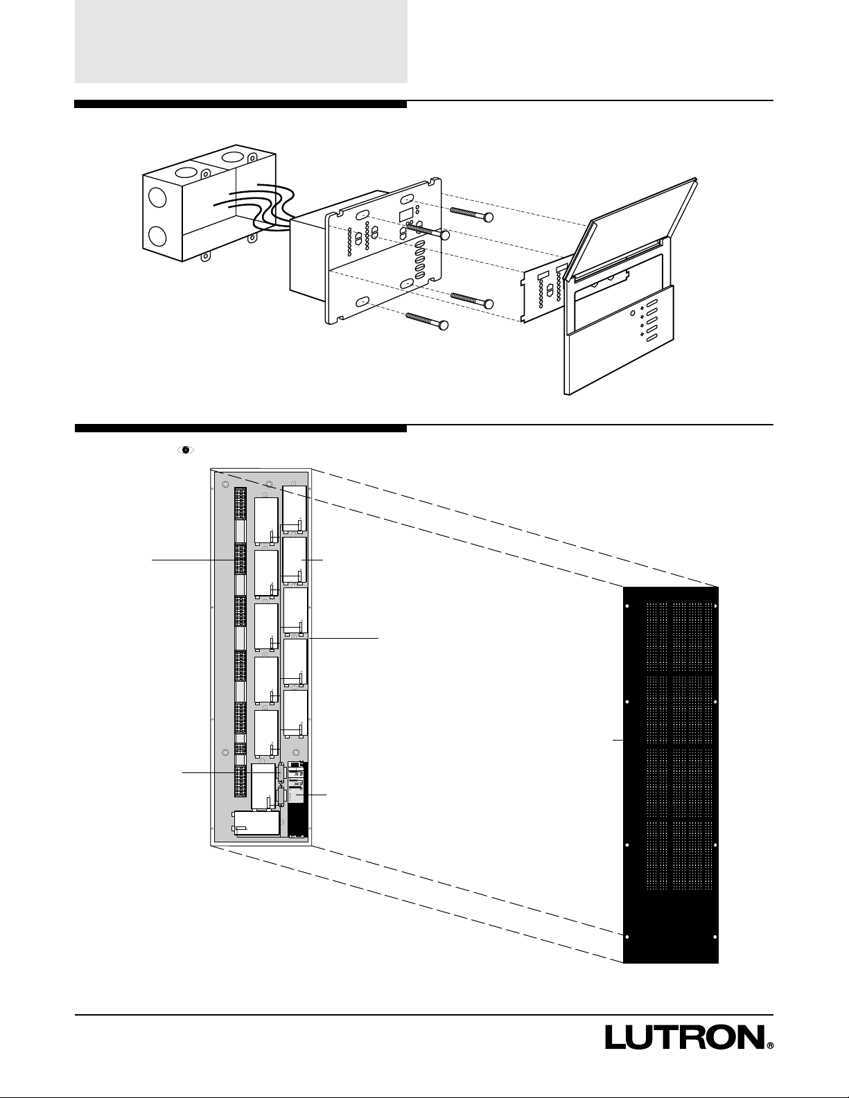
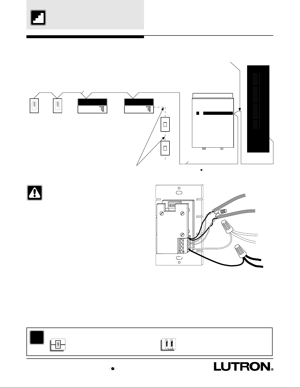
Overview
GRX-4000 Series Control Unit
GRAFIK Eye XP Series Panel
TERMINAL BLOCKS
CLASS 2 TRANSFORMERS
SWITCHING MODULE
PANEL
N
N
H
H
12345
Power (Pins
Link
Data (Pins
S
elecCircui
1
2
Circ
VIEV
AL
S
elecValu
3
4
Val
S
elecValuDisplay
5
Load
1
4 Non-
2
5 Elec.
_
3
Unassig
Control and Zone
Using circuit
Using Zone
T
Low End (optio
High End (optio
Circuit
R
LUTR
R
LUTR
CIRCUIT SELECTOR
COVER
2
Page 3
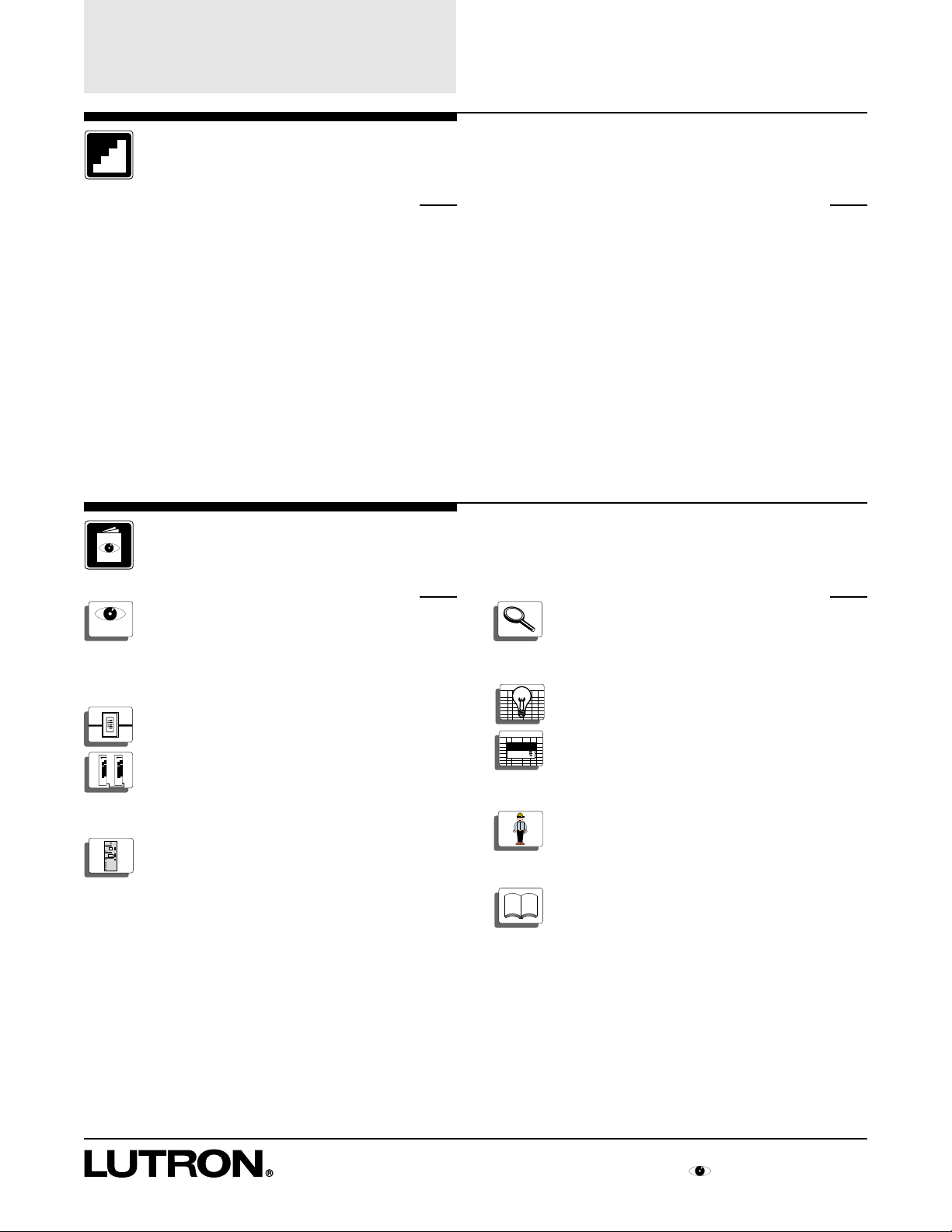
Table of Contents
B
e
l
i
e
v
eit
o
r
n
o
t
,
t
h
i
s
i
s
s
u
p
p
o
s
e
d
t
o
l
o
o
k
l
i
k
e
a
d
i
c
t
i
o
n
a
r
y
!
T
h
i
s
i
c
on
w
a
s
c
r
e
a
t
e
d
b
y
B
r
e
n
t
M
.
N
y
e
,
J
u
l
y
6
,
1
9
9
5
.
B
e
l
i
e
v
eit
o
r
n
o
t
,
t
h
i
s
i
s
s
u
p
p
o
s
e
d
t
o
l
o
o
k
l
i
k
e
a
d
i
c
t
i
o
n
a
r
y
!
T
h
i
s
i
c
on
w
a
s
c
r
e
a
t
e
d
b
y
B
r
e
n
t
M
.
N
y
e
,
J
u
l
y
6
,
1
9
9
5
,
u
n
d
e
r
the
d
i
r
e
c
t
i
o
n
o
f
D
e
r
e
k
R
.
T
h
o
m
a
s
.
T
h
i
s
i
c
on
w
a
s
c
r
e
a
t
e
d
b
y
B
r
e
n
t
M
.
N
y
e
,
J
u
l
y
6
,
1
9
9
5
.
B
e
l
i
e
v
eit
o
r
n
o
t
,
t
h
i
s
i
s
s
u
p
p
o
s
e
d
t
o
l
o
o
k
l
i
k
e
a
d
i
c
t
i
o
n
a
r
y
!
T
h
i
s
i
c
on
w
a
s
c
r
e
a
t
e
d
b
y
B
r
e
n
t
M
.
N
y
e
,
J
u
l
y
6
,
1
9
9
5
.
B
e
l
i
e
v
eit
o
r
n
o
t
,
t
h
i
s
i
s
s
u
p
p
o
s
e
d
t
o
l
o
o
k
l
i
k
e
a
d
i
c
t
i
o
n
a
r
y
!
T
h
i
s
i
c
on
w
a
s
c
r
e
a
t
e
d
b
y
B
r
e
n
t
M
.
N
y
e
,
J
u
l
y
6
,
1
9
9
5
.
B
e
l
i
e
v
eit
o
r
n
o
t
,
t
h
i
s
i
s
s
u
p
p
o
s
e
d
t
o
l
o
o
k
l
i
k
e
a
d
i
c
t
i
o
n
a
r
y
!
T
h
i
s
i
c
on
w
a
s
c
r
e
a
t
e
d
b
y
B
r
e
n
t
M
.
N
y
e
,
J
u
l
y
6
,
1
9
9
5
.
u
n
d
e
r
the
d
i
r
e
c
t
i
o
n
o
f
D
e
r
e
k
R
.
T
h
o
m
a
s
.
T
h
i
s
i
c
on
w
a
s
c
r
e
a
t
e
d
b
y
B
r
e
n
t
M
.
N
y
e
,
J
u
l
y
6
,
1
9
9
5
.
B
e
l
i
e
v
eit
o
r
n
o
t
,
t
h
i
s
i
s
s
u
p
p
o
s
e
d
t
o
l
o
o
k
l
i
k
e
a
d
i
c
t
i
o
n
a
r
y
!
T
h
i
s
i
c
on
w
a
s
c
r
e
a
t
e
d
b
y
B
r
e
n
t
M
.
N
y
e
,
J
u
l
y
6
,
1
9
9
5
.
Step-by-Step Instructions
Install System Page
STEP 1: Mount Wallboxes ................................... 2
STEP 2: Mount Panels....................................... 2,3
STEP 3: Wire System......................................... 4,5
STEP 4: Set Address Switches..............................6
STEP 5: Set Function Switches.............................7
STEP 6: Install Controls.........................................8
Start Up System
STEP 7: Activate Loads in Bypass........................8
STEP 8: Activate Controls..................................... 9
STEP 9: Assign Load T ypes................................10
STEP 10: Address GRX-4000 Control Units......... 11
STEP 11: Remove Bypass Jumpers..................... 12
STEP 12: Check System....................................... 13
Reference Sheets
Look Inside a Panel Page
XP
XP Series Panels..................................20
Set Up System Page
STEP 13: Assign Zones.........................................14
STEP 14: Set Up Scenes on the GRX-4000......... 15
STEP 15: Set Up Accessory Controls...............16,17
STEP 16: Set Normal/Emergency Switch............. 18
Troubleshooting Guide Page
Troubleshooting Guide.......................24,25
Control Wiring
Accessory to Control Unit to Panel .......21
Panel to Panel ......................................22
Circuit Selector
Circuit Selector Functions.....................23
Directories
Circuit Directory ......................................26
Control Directory.....................................27
Maintenance
Maintenance ...........................................28
Glossary of Terms
Glossary of Terms...................................29
Table of Contents for GRAFIK Eye Switching Panel
3
Page 4
Mount Wallboxes and
Panels
STEP 1: Mount Wallboxes
Use wallboxes with a minimum depth of 2-3/4"
(70mm) for Accessory Controls and 3-1/2" (89mm)
for GRX-4000 Series Control Units.
Multigang installations may require spacers between
wallboxes.
Mount wallboxes flush to 1/8" (3mm) below finished
wall surface.
Finished wall should not have gaps around the
wallbox of greater than 1/8" (3mm).
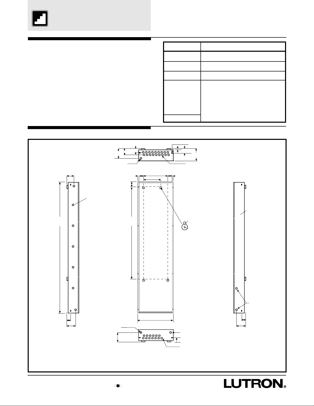
STEP 2: Mount Panels
XP Series
(Dimensions and Conduit Entry)
2"
2-5/16" (6.7cm)
Preferred feed and load
wire entry—may be
expanded to 2" max.
2-1/8"
2-7/16"
(6.2cm)
3/8"
3/4"
1-5/8"
Top View
11" (28 cm)
8" (20 cm)
Control
GRX-CIR
GRX-4S-DW
GRX-AV‘s
GRX-4000 Series
Control Units
2 zone (2 gang)
3 zone (3 gang)
4 zone (4 gang)
6 zone (4 gang)
8 zone (4 gang)
All Others (1 gang)
Slot for recessed mounting
1/8"
3/8"
screws (8 places)
1"
4-1/16" (10.3cm)
7/8" diameter knock out (44 places)
Wallbox
Mounts in Ceiling with special mounting ring (provided)
Lutron # 241-399 (provided)
1900 Box (4"x4" junction box) or Lutron #241-496
Lutron # 241-519 3-1/2" (89mm) deep
(1 gang each, gangable)
or
2-3/4" (70mm), 3-1/2" (89mm) deep US Wallbox
Left side may
be punched
59"
(150cm)
Left Side Right Side
1
2-1/4"
WHEN SURFACE MOUNTING, THE KEYHOLE
ACCEPTS A MAXIMUM OF 1/4" MOUNTING
BOLT (1/4" IS RECOMMENDED)
WHEN FLUSH MOUNTING, MOUNT PANEL
FLUSH TO 1/8" (3MM) BELOW FINISHED WALL
SURFACE
Front View
Second preferred feed and
load wire entry—may be
extended to 2" max.
2-5/16" (5.9cm)
41-3/4"
(106cm)
15-1/8" (38.4cm)
Bottom View
.312 dia.
.624 dia.
Keyholes for
surface mounting
(4 places)
Class 2 (SELV) only
alternate control
wiring entry
1" (2.5cm)
No entrance on all
x'd out knockouts
READ THE MAINTENANCE REFERENCE SHEET
BEFORE PAINTING THE PANEL OR COVER
2-1/4"
(5.7cm)
1"
No entrance on right
side except Class 2
knockouts
Class 2 (SELV) only
control wiring entry
2
Step by Step instructions for GRAFIK Eye Switching Panel
Page 5

Mount Wallboxes and
Panels
STEP 2: Mount Panels (cont.)
FEED AND LOAD
CIRCUIT WIRING
DISTRIBUTION
PANEL
ALTERNATE
FEED AND
LOAD CIRCUIT
WIRING
Suggested Surface Mount
CEILING
CLASS 2 (SELV)
WIRING TO
CONTROLS
N
N
H
H
12345
Power (Pins
Link
Data (Pins
S
elecCircui
1
2
Circ
VIEV
AL
S
elecValu
3
4
Val
S
elecValuDisplay
5
Load
4 Non-
1
5 Elec.
2
_
Unassig
3
Control and Zone
Using circuit
Using Zone
T
Low End (optio
High End (optio
Circuit
LUTR
R
R
LUTR
WALL
FEED AND LOAD
CIRCUIT WIRING
DISTRIBUTION
PANEL
ALTERNATE
FEED AND
LOAD CIRCUIT
WIRING
Suggested Recess Mount
CEILING
CLASS 2 (SELV)
WIRING TO
CONTROLS
N
N
H
H
12345
Power (Pins
Link
Data (Pins
S
elecCircui
1
2
Circ
VIEV
AL
S
elecValu
3
4
Val
S
elecValuDisplay
5
Load
1
4 Non-
2
5 Elec.
_
3
Unassig
Control and Zone
Using circuit
Using Zone
T
Low End (optio
High End (optio
Circuit
LUTR
R
R
LUTR
WALL
Front View Side View Front View Side View
Notes:
• Keep length of raceway below 24" to avoid possible
derating (per NEC code for 10 or more conductors).
• Panel generates heat (see table at right). Mount
only where ambient temperature will be 0-40°C
(32°F-104°F).
• Reinforce wall structure as required for weight and
local codes.
• Panel clearances are 1-1/2" (38mm) to each side.
• Distribution Panel not included with XP Series Panel.
• Indoor Use Only. Type 1 enclosure.
• Relative Humidity < 90% non-condensing.
• XP Panels should be mounted within 7° of true
vertical.
For More Information...
?
Look inside an XP........................... 20
XP
Weight w/o PackagingPanel
55 lbs (25 kg)
60 lbs (27 kg)
70 lbs (32 kg)
XP-24
XP-32
XP-48
Max BTU/Hrs.
310
350
430
Caution - Internal relays will click while in
operation. Mount where audible noise is
acceptable.
Caution - Where and how the XP panel is
mounted may depend upon the wiring
method you choose (see step 3).
Step by Step instructions for GRAFIK Eye Switching Panel
3
Page 6
Wire System
STEP 3: Wire System
GRX Wiring
2 #12 AWG (2.5mm2) FROM TERMINALS 1 TO 1, AND 2 TO 2
2 #18 AWG (1.0mm
BELDEN #9461 OR ALPHA #2211 ARE #22 AWG AND ARE RECOMMENDED.
ALL 4 WIRES ARE AVAILABLE IN ONE CABLE FROM LIBERTY CABLE AT 1-800-530-8998.
LIBERTY P/N IS LUCOM-12/22-RBL
NOTE: TOTAL LENGTH OF WIRE MAY BE NO MORE THAN 2000 FEET FOR #12 AWG
2
) TWISTED SHIELDED PAIR FROM TERMINALS 3 TO 3, AND 4 TO 4 -
(450m for 2.5mm
2
).
CLASS 2 WIRING
FOR PANEL TO PANEL WIRING, INCLUDE AN ADDITIONAL 1 #18 AWG (1.0mm
BETWEEN PANELS FROM TERMINALS 5 TO 5.
NOTE: WIRING LIMITATIONS INCLUDE
PANEL TO PANEL WIRING.
2
)
SEQUENCE
ZONE LOCK
SCENE LOCK
FADE OVERRIDE
ACCESSORY
CONTROLS
(16 MAX.)
NTGRX-4S
NTGRX-4S-IR
GRX-CIR
GRX-4S-DW
NTGRX-RL
NTGRX-4Q
NTGRX-4PS
NTGRX-4M
GRX-AV
GRX-AV-SER
GRX-AV-RS232
GRX-AV-RS232/ATC
NTGRX-2B
SEQUENCE
ZONE LOCK
SCENE LOCK
FADE OVERRIDE
LUTRON
GRX-4000 SERIES CONTROL UNITS
# = 1 for GRX-4100’s, 5 for GRX-4500’s
2 #18 AWG (1mm
SSA AND SSARET OF THE
INDIVIDUAL CONTROL UNIT TO HAVE
ITS SCENE 1 TOGGLED ON AND OFF.
(8 MAX.)
GRX-4#02 (2 zone)
GRX-4#03 (3 zone)
GRX-4#04 (4 zone)
GRX-4#06 (6 zone)
GRX-4#08 (8 zone)
LUTRON
2
) TO TERMINALS
Caution - Wire in a daisy-chain
arrangement as shown - no variations.
Do not substitute cables!
Notes:
• All control wiring is Class 2 (Extra Low Voltage).
Do not place any of these wires in with line voltage
(mains voltage) wiring.
• Panel may be placed in the middle of the wiring as
opposed to on the end as shown, but panel to
panel wiring may be more difficult.
• 2 #12 AWG (2.5mm2) wires will not fit in the
Accessory Control terminal blocks. Use the
diagram shown at right to make the connections
in the wallbox. #12 AWG (2.5mm2) is necessary
due to voltage drop on the wire.
• Shielding must be connected as shown, but do not
connect to Ground (Earth) or Accessory Control. It
is easiest to connect the bare drain wires and cut
off the outside shield.
• Make wire connections inside the wallbox, GP and
XP panel or in a junction box (provided by others)
within 8ft. (2.4m) from the terminals.
LUTRON
LUTRON
CLASS 2 WIRING
SSA CONTROLS
(10 MAX.)
NTGRX-1S
GRAFIK Eye GP, LP, or XP SERIES LIGHTING CONTROL PANELS
(Number of panels max = 33 - Number of Control Units -
4
3
2
1
Number of Accessory Controls)
-SHIELD/DRAIN
2 #12 AWG (2.5mm2)
1 #18 AWG
(1mm2)
2 #12 AWG (2.5mm
2
)
• Maximum number of lighting control panels may
be increased using a repeater—contact Lutron.
• The following cables: Liberty #LUCOM-12/22-RBL,
Belden #9461, and Alpha #2211 are made with #22
AWG wire, and have been tested and approved.
Not all #22 AWG cable will work. Any #18 AWG
twisted, shielded pair will work.
For More Information...
?
Accessory Control to Control Unit Panel to Panel Wiring.................................22
to Panel Wiring.................................21
4
Step by Step instructions for GRAFIK Eye Switching Panel
Page 7
Wire System
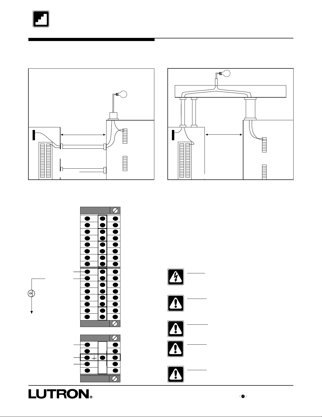
STEP 3: Wire System (cont.)
Suggested wiring when panels are close together
Suggested wiring when panels are far apart
Neutral Wire (N)
Hot/Live
Wire (H)
Distribution Panel
Module wiring
Hot/Live In
Switched Hot
Load 16 A max
Neutral
Large
Distance
H
SH
H
SH
H
SH
H
SH
H
SH
H
SH
H
SH
H
SH
SH
Small
Load 16A Max.
SH
H
Splice Neutrals
in Trough
SH
H
Switched Hot/Live
Wire (SH)
XP Panel
N
N
SH
XP Panel
Load 16A Max.
H
Switched Hot/Live
Wire (SH)
Neutral
Wire (N)
Hot/Live
Wire (H)
Distribution Panel
N
N
H
H
Distance
Notes:
• Terminal blocks accept one #14 AWG (2.5mm2)
through #10 AWG (4.0mm2) or two AWG #18 AWG
through #16 AWG wire.
• Two modules and the control feed are shown to the
left. The module terminal blocks are typical of the
rest of the possible 12 modules
• Lutron recommends that the Control Feed be a
dedicated circuit even though the control wiring
will draw 0.5 Amps max.
Danger - An XP Series panel is fed by
multiple circuits. Locate and lock each
feed in the OFF position.
Caution - XP Series panels require entry
of wires as specified. Improper entry will
block serviceable parts or violate NEC codes.
Warning - Do not remove bypass jumpers
at this step.
Neutral
Ground
Dedicated Hot/Live
N
N
H
H
Reference Sheets for GRAFIK Eye Switching Panel
Caution - Lutron recommends the use of
a trough for ease of wiring (where space
permits).
Caution - Follow all local wiring codes.
5
Page 8
Set Address Switches
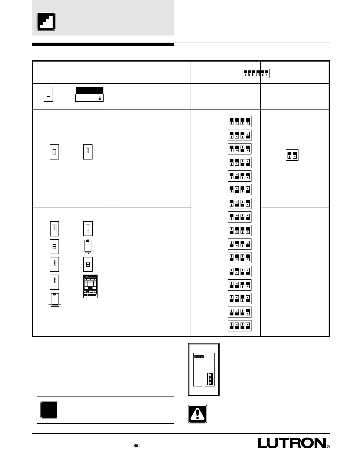
STEP 4: Set Address Switches
Control
LUTRON
LUTRON
NTGRX-1S GRX-4000 Series
No switches for addressing.
Go to Step 6 if no other types of
Accessory Controls.
Action
Address
Control 1
N/A
1 2 3 4 5 6
Function
Factory Set
N/A
1 2 3 4
1
2
3
4
LUTRON
PARTITION STATUS
OPEN
CLOSED
NTGRX-RL NTGRX-4PS
SEQUENCE
ZONE LOCK
SCENE LOCK
FADE OVERRIDE
LUTRON
LUTRON
LUTRON
1 2 3 4 5 6
LUTRON
1 2 3 4 5 6
LUTRON
GRX-AV
Must set switches BEFORE
installing these controls.
Set Switches 1-4 on each
Accessory Control to a unique
address.
Must set switches BEFORE
installing these controls.
Set Switches 1-4 on each
Accessory Control to a unique
address.
Set Switches 5-6 to define the
function of control.
Control 2
Control 3
Control 4
Control 5
Control 6
Control 7
Control 8
Control 9
Control 10
Control 11
Control 12
Control 13
Control 14
5 6
Leave switches as factory
set.
Go to Step 6 if no other
types of Accessory controls.
Setting Switches 5 and 6
requires system knowledge.
See Step 5 for function
options.
ALL OTHERS
Notes:
• GRX-AV has 8 switch positions. Positions 7 and 8
also set the function.
• GRX-AV-RS232’s do not have an address—
follow instructions packaged with each control
and skip to step 6.
For More Information...
?
6
Step by Step instructions for GRAFIK Eye Switching Panel
See also One-Line Diagram from submittals.
Control 15
Control 16
Back of Accessory Control
Switch
location
4
3
2
1
Caution - Do not install controls in
wallbox without setting the Address and
Function Switches.
Page 9
LUTRON
R
LUTRON
R
Set Function Switches
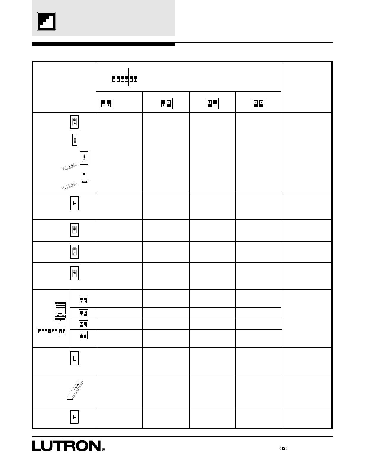
STEP 5: Set Function Switches
Accessory Control
NTGRX-4S,
GRX-4S-DW
NTGRX-4S-IR
w/GRX-IT,
GRX-CIR
w/GRX-IT
NTGRX-RL
NTGRX-4Q
LUTRON
LUTRON
1 2 3 4 5 6
LUTRON
SEQUENCE
ZONE LOCK
SCENE LOCK
FADE OVERRIDE
1 2 3 4 5 6
Function Set by Switches
on Back of Control
Factory Set
5 6 5 6 5 6 5 6
Factory Set
Activate Scenes 1-4
Not Applicable
Sequence Scenes 1-4
Activate Scenes 5-8
Not Applicable
Not Applicable
Activate Scenes 9-12
Not Applicable
Not Applicable
Activate Scenes 13-16
Not Applicable
Sequence Scenes 5-16
Function Set
with Front
Buttons
(See Step 17)
Activate Scenes on
specified GRX-4000
Series Control Units
Raise/Lower specified
Zones on specified
GRX-4000 Series
Control Units
Affect specified GRX4000 Series Control
Units
NTGRX-4PS
NTGRX-4M
GRX-AV
GRX-AV
7 8
Factory Settings
NTGRX-1S
GRX-IT
GRX-8IT
NTGRX-2B
1
2
3
4
PARTITION STATUS
OPEN
CLOSED
Not Applicable
Fifth button turns
LUTRON
Control Units On only.
Not Applicable
Not Applicable
Not Applicable
Not Applicable
Not Applicable
Fifth button turns
Control Units Off only.
Parallel specified GRX4000 Series Control
Units
Toggle 4 specified
groups of GRX-4000
Series Control Units On
and Off.
7 8
LUTRON
Momentary Input
Activate Scenes 1-4
Momentary Input
Sequence Scenes 1-4
Momentary Input
4PS functions
Momentary Input
1 Channel fine tuning
Not Applicable
Momentary Input
Activate Scenes 9-12
Momentary Input
Sequence Scenes 5-16
N/A
Momentary Input
NTGRX-4M Function
Not Applicable
Momentary Input
Activate Scenes 5-8
Maintained Input
Sequence Scenes 1-4
Maintained Input
4PS functions
Maintained Input
Occupant Sensor
Scene 1 and Off
Not Applicable
Momentary Input
Activate Scenes 13-16
Maintained Input
Sequence Scenes 5-16
N/A
Maintained Input
Occupant Sensor
Off Only
Not Applicable
Affect specified GRX4000 Series Control
Units
Toggle between Scene 1
and Off of connected
GRX-4000 Series
Control Unit
Not Applicable
Not Applicable
Not Applicable
Not Applicable
Activate Scenes 1-4 or
1-8 and Off, and Raise/
LUTRON
R
Lower all zones of target
GRX-4000 Series
Control Unit
LUTRON
Activate Scene 1 and
Off
Activate Scenes 13
and 14
Single Partition
Function
Activate Scene 16 w/
lockout or previous
Scene w/o lockout
Affect specified GRX4000 Series Control
Units
Step by Step instructions for GRAFIK Eye Switching Panel
7
Page 10
Faceplate
Adapter
Control Facepla
Adapter M
Screws
Control Mounting
Screws
Wallbox
Control
Link
Install Controls and
Activate Loads
STEP 6: Install Controls
After completing steps 4 and 5, mount controls.
Refer to detailed mounting instructions packaged with
each control.
STEP 7: Activate Loads in Bypass
A. Check that the bypass jumpers are in place.
These jumpers protect the switch mechanism from
wiring faults and must be used to check load wiring
when it is installed or modified.
B. Complete load wiring.
C. Turn a load’s input circuit breaker ON.
The loads should energize, the feed breaker should
not trip, and total load current must be no more
than 16 Amps.
D. Repeat ‘C.’ for each circuit with completed load
wiring.
WALLBOX
CONTROL
LINK
CONTROL
CONTROL
MOUNTING SCREWS
FACEPLATE
ADAPTER
ADAPTER
MOUNTING SCREWS
FACEPLATE
Warning - DO NOT remove bypass
jumpers at this time.
2 position
Bypass
Jumper
N
N
H
H
12345
Power (Pins
Link
Data (Pins
S
electCircuit
1
2
Circui
VIEV
ALU
S
electValue
3
4
Valu
S
electValueDisplayed
5
Load
1 Inc/Mag
4 Non-
2
5 Elec.
_
3
Unassigne
Control and Zone
Using circuit
T
Using Zone
Low End (optional
High End (optional
Circuit
R
LUTRO
R
LUTRO
8
Step by Step instructions for GRAFIK Eye Switching Panel
Page 11

Activate Controls
STEP 8: Activate Controls
Once all controls are installed and wiring verified, turn
the control wiring feed circuit breaker ON.
Check that the Power OK LED at the top of the
Circuit Selector is ON. If the Power OK LED is
off, turn off the control breaker, check for shorts
between wires 1 and 2, or 2 and ground.
Note:
For multiple panels once one Power OK LED is
ON, all the Power OK LED’s in all system Circuit
Selector’s should turn ON.
Circuit
Value
4 Non-dim
5 Elec. LV
– Unassigned
Power OK (Pins 1,2)
Data OK (Pins 3,4)
TM
Link Status
S
ELECT CIRCUIT
V
IEW VALUE
S
ELECT VALUE
S
ELECT VALUE DISPLAYED
Load Type
1 Inc/Mag LV
2 Fluorescent
3 Neon/CC
Control and Zone Assigned
Using circuit schedule
Using Zone Capture
Low End Trim (optional)
High End Trim (optional)
Circuit Level
1
2
3
4
5
®
‘Power OK’ LED
Push scene buttons on Accessory Controls. All GRX4000 Series Control Units and Accessory Controls
should act in parallel (e.g. pressing scene 1 on a
control will select scene 1 on all controls, pressing a
raise button will raise all zones).
Notes:
• NTGRX-4Q, NTGRX-4PS, NTGRX-4M
and GRX-AV-RS232’s will be inactive until
Control Set Up is completed.
• GRX-AV will be active only if set to affect Scenes
1-4 and OFF (switches 5,6,7, and 8 all UP).
• NTGRX-2B will be active only if set to affect Scene
1 and OFF (switches 5 and 6 both UP).
• Check for miswires if the controls do not act as
described.
ZONE 6ZONE 5ZONE 4ZONE 3ZONE 2ZONE 1
LUTRON
FADE OVERRIDE
SM
GRX-4000 Series Control Unit
(6 zone unit shown)
Push
LUTRON
ZONE
MASTER
Push
?
For More Information...
Troubleshooting Guide.................24, 25
Accessory Control
(NTGRX-4S shown)
Step by Step instructions for GRAFIK Eye Switching Panel
9
Page 12

Assign Load Types
STEP 9: Assign Load Types
Assigning Load Types is done using the Circuit
Selector located in each XP Series panel.
Press button 5 repeatedly until Load Type lights.
Use buttons 1 and 2 to view present load type of each
circuit. Note that ‘ - ’ in the Value display means a
Load Type is not assigned to the circuit.
If load types are already assigned, compare them to
the Circuit Directory (if provided).
If there are no changes to be made, skip to Step 10.
To change Load Types:
A. Press and hold buttons 1 and 5 until
SELECT VALUE
LED lights.
B. Press button 5 repeatedly until Load Type lights.
C.Tap button 2 so that ‘AC’ (All Circuits) appears in
the Circuit display.
D.Press button 3 repeatedly (press button once per
second since updating is slower in all circuits) until
‘4’ appears in the Value display.
E. Press and hold buttons 1 and 5 until
VIEW VALUE LED lights.
Notes:
• Most applications will use Load Type 4. Use Load
Type 6 for circuits controlling screens.
• The Circuit Selector Display will go out automatically
after 20 minutes of the last button press.
• Mark all changes to the Circuit Selector’s Values on
the Circuit Directory for future reference.
Circuit Selector
Circuit
Value
4 Non-dim
5 Elec. LV
– Unassigned
Circuit
Value
4 Non-dim
5 Elec. LV
– Unassigned
Power OK (Pins 1,2)
Data OK (Pins 3,4)
TM
Power OK (Pins 1,2)
Data OK (Pins 3,4)
44
4
44
TM
Link Status
S
ELECT CIRCUIT
V
IEW VALUE
S
ELECT VALUE
S
ELECT VALUE DISPLAYED
Load Type
1 Inc/Mag LV
2 Fluorescent
3 Neon/CC
Control and Zone Assigned
Using circuit schedule
Using Zone Capture
Link Status
Low End Trim (optional)
High End Trim (optional)
S
ELECT CIRCUIT
Circuit Level
V
IEW VALUE
S
ELECT VALUE
S
ELECT VALUE DISPLAYED
Load Type
1 Inc/Mag LV
2 Fluorescent
3 Neon/CC
Control and Zone Assigned
Using circuit schedule
Using Zone Capture
Low End Trim (optional)
High End Trim (optional)
Circuit Level
1
2
3
4
5
1
®
2
3
4
5
®
A,F
For More Information...
?
Circuit Selector Functions.................23
Circuit Directory.................................26
10
Step by Step instructions for GRAFIK Eye Switching Panel
Page 13

Address GRX-4000
Control Units
STEP 10: Address GRX-4000 Control
Units
Push the scene 1 button on a GRX-4000 Series
Control Unit. The scene 1 LED should go on.
Address Control Unit as follows:
A. Push and hold top and bottom scene buttons until
scene LEDs begin to cycle.
B. Push FADE button until ‘A-’ is displayed in the
FADE window. If A1 through A8 appears, then go
to D since the Control Unit is already addressed.
C.Push MASTER button once. The control will
automatically choose the next available address.
Note the address of each on the Control Directory
(A1-A8).
If a Control or Load Directory already exists, push
MASTER and buttons to have the address
match these directories.
D.Push and hold the top and bottom buttons until the
scene LEDs stop cycling.
Repeat Steps A-D on all GRX-4000 Series Control
Units.
ZONE 6ZONE 5ZONE 4ZONE 3ZONE 2ZONE 1
LUTRON
FADE OVERRIDE
SM
GRX-4000 Series Control Unit
ZONE
MASTER
B
C
A,D
As soon as a GRX-4000 Series Control Unit is
addressed, check that the Data OK LED (located
below the Power OK LED on the Circuit Selector)
begins to blink. Blinking indicates that the wiring from
a GRX-4000 Series Control Unit to the panel is
correct.
Note:
As soon as a GRX-4000 Series Control Unit is
addressed, Accessory Controls will no longer have
any affect on the GRX-4000 Series Control Units.
The Accessory Controls will be reactivated in
Step 16.
For More Information...
?
Troubleshooting Guide.................24, 25
Circuit
Value
4 Non-dim
5 Elec. LV
– Unassigned
Power OK (Pins 1,2)
Data OK (Pins 3,4)
TM
Link Status
S
ELECT CIRCUIT
V
IEW VALUE
S
ELECT VALUE
S
ELECT VALUE DISPLAYED
Load Type
1 Inc/Mag LV
2 Fluorescent
3 Neon/CC
Control and Zone Assigned
Using circuit schedule
Using Zone Capture
Low End Trim (optional)
High End Trim (optional)
Circuit Level
Not lit before addressing
Blinking after
1
2
3
4
5
addressing
(approximately once per
second)
®
Control Directory...............................27
Step by Step instructions for GRAFIK Eye Switching Panel
11
Page 14

Remove Bypass
Jumpers
STEP 11: Remove Bypass Jumpers
Repeat Step 7 if load wiring has been modified.
Turn circuit breakers OFF.
Danger - Do not remove or replace
bypass jumpers while power is ON.
Loosen both screws of each bypass jumper.
Remove and store the bypass jumpers for possible
later use.
Store the bypass jumpers at the bottom of the panel.
DO NOT place them on top of the module.
Warning - When working on any load
(such as replacing a bulb), turn Off
power to the module that powers the
load. Turn the module power off by
switching its input circuit breaker
(MCB) Off.
Turning ON to a load fault WILL
irreparably damage the switch module.
Damage caused by short circuits and
miswiring is not covered in the product
warranty.
BYPASS JUMPERS—
Replace whenever a load
is serviced.
H
SH
H
SH
H
SH
H
SH
H
SH
H
SH
H
SH
H
SH
Terminal blocks
for 2 modules
Turn Circuit Breakers ON.
12
Step by Step instructions for GRAFIK Eye Switching Panel
Page 15

Check System
STEP 12: Check System
Until zones are assigned in Step 13, all circuits will be
controlled by the first zone of the GRX-4000 Series
Control Unit addressed to ‘A1’. Locate zone 1 of this
‘A1’ control (referred to as A1 1 in the Circuit Selector)
and use it to check that all circuits turn ON and OFF
as expected.
(This address was set in Step 10.)
Note:
If the system has already been Set Up, scenes will
work and A1 1 will not control all circuits.
ZONE 6ZONE 5ZONE 4ZONE 3ZONE 2ZONE 1
LUTRON
First zone of GRX-4000 Series
Control Unit addressed ‘A1’
FADE OVERRIDE
SM
ZONE
MASTER
STOP!
?
To assure proper Set Up, you must have
one or more of the following:
• Factory Customized Set Up.
• Knowledge of how the system is
to operate.
• Plans and specifications from owner’s
representative on how the system is to
be set-up.
• Owner or owner’s representative
For More Information...
Circuit Directory.................................26
Possible questions:
•
What should each scene be used for?
Examples include - Day lighting, Night lighting,
Meeting, Accenting, etc...
•
Which circuits should be on in each scene?
Control Directory...............................27
Step by Step instructions for GRAFIK Eye Switching Panel
13
Page 16

Assign Zones
STEP 13: Assign Zones
A. Press and hold buttons 1 and 5 until
SELECT VALUE
lights.
B. Press button 5 repeatedly until
Using Circuit Schedule lights.
C.Use buttons 3 and 4 to assign control (factory set
to A1) and zone (factory set to 1) for each circuit.
Whichever item is blinking can be changed. See
the Control Schedule for control locations. If zones
are already assigned, skip to Step 15.
Example - If the control desired is addressed to
‘A2’ and the zone desired is the 3rd from the left,
use buttons 3 and 4 to get ‘A23’ as a value for the
appropriate circuit.
D.Use buttons 1 and 2 to change to the next circuit
and then repeat Step C. Do this for all affected
circuits. Record each circuit’s control and zone on
the Circuit Directory.
E. Press and hold buttons 1 and 5 until
VIEW VALUE lights. The Circuit Selector’s
display will go out automatically after 20 minutes
of the last button push.
Notes:
• More than one circuit can be assigned to the
same zone.
•
Zone Capture TM
assigning zones. It is described in the Circuit
Selector Functions Reference Sheet.
is an alternate method for
Circuit
Value
4 Non-dim
5 Elec. LV
– Unassigned
Circuit
Value
4 Non-dim
5 Elec. LV
– Unassigned
Power OK (Pins 1,2)
Data OK (Pins 3,4)
TM
Power OK (Pins 1,2)
Data OK (Pins 3,4)
TM
Link Status
S
ELECT CIRCUIT
V
IEW VALUE
S
ELECT VALUE
S
ELECT VALUE DISPLAYED
Load Type
1 Inc/Mag LV
2 Fluorescent
3 Neon/CC
Control and Zone Assigned
Using circuit schedule
Using Zone Capture
Low End Trim (optional)
High End Trim (optional)
Circuit Level
Link Status
S
ELECT CIRCUIT
V
IEW VALUE
S
ELECT VALUE
S
ELECT VALUE DISPLAYED
Load Type
1 Inc/Mag LV
2 Fluorescent
3 Neon/CC
Control and Zone Assigned
Using circuit schedule
Using Zone Capture
Low End Trim (optional)
High End Trim (optional)
Circuit Level
1
2
A,E
3
4
5
®
1
2
3
4
5
®
For More Information...
?
Circuit Selector Functions.................23
Circuit Directory.................................26
Control Directory...............................27
14
Step by Step instructions for GRAFIK Eye Switching Panel
Page 17

Set Up Scenes on the
GRX-4000
STEP 14: Set Up Scenes on the GRX-4000
A. Lift the cover flap on a GRX-4000 Series Control
Unit (flap hinges up).
B. Press the Scene 1 button.
C.Press and buttons of each zone to create a
scene. As soon as a zone is changed, the GRX4000 Series Control Unit will remember it.
D.Adjust the fade time using and FADE
buttons.
Note:
The fade time can be adjusted from 0 to 59
seconds or 1 to 60 minutes.
E. Press Scene 2 and repeat C-D. Do this for all
scenes.
Note:
Off scene may have Fade time adjusted.
F. Repeat Steps A-E for all of the GRX-4000 Series
Control Units on the job.
ZONE 6ZONE 5ZONE 4ZONE 3ZONE 2ZONE 1
LUTRON
GRX-4000 Series Control Unit
FADE OVERRIDE
ZONE
SM
MASTER
DC
A
B
E
Step by Step instructions for GRAFIK Eye Switching Panel
15
Page 18

Set Up Accessory
LUTRON
R
Controls
STEP 15: Set Up Accessory Controls
All Accessory Controls (except NTGRX-1S) must be
set up to make a Control Unit(s) “listen” to button
presses on the Accessory Control.
• Only one Accessory Control can be set up at one
time.
• A Control Unit can also be made to “listen” to
another Control Unit and is therefore listed with the
Accessory Controls at right.
Follow Steps A-C for each Accessory Control.
Notes:
• Accessory Controls can not be made to “listen” to
each other , but a GRX-4000 Series Control Unit
can be made to “listen” to more than one
Accessory Control.
• When it is desired for two GRX-4000 Series
Control Units to always respond to each other’s
button presses, the first Control Unit must be set up
to respond to the second Control Unit’s buttons,
and then the second Control Unit must be set up to
respond to the first Control Unit’s buttons.
• An NTGRX-1S is wired directly to the GRX-4000
Series Control Unit that is to “listen” to it. No set-up
is required.
• GRX-AV-RS232’s do not follow this chart. See
instructions packaged with each control.
STEP A: Place Control to ‘Talk’ in Set-Up Mode
Control
(only 1 at a time)
GRX-4000
Series Control
Unit
NTGRX-4S
NTGRX-4Q
NTGRX-4S-IR
GRX-CIR
w/GRX-IT
GRX-4S-DW
NTGRX-RL
NTGRX-4PS
LUTRON
Press and hold first and fifth buttons of a Control
Unit.
LUTRON
SEQUENCE
ZONE LOCK
SCENE LOCK
FADE OVERRIDE
Press and hold first and fifth buttons on Accessory
Control until its LEDs cycle sequentially.
LUTRON
Note: GRX-CIR only has 1 LED. Use the GRX-IT
1 2 3 4 5 6
to activate the first and fifth buttons.
Press and hold Raise and Lower buttons of
LUTRON
NTGRX-RL until its LED blinks (LED is located
behind faceplate)
Press and hold first and fifth buttons of the
1
2
3
4
PARTITION STATUS
OPEN
CLOSED
NTGRX-4PS until LED 1 blinks.
Action
NTGRX-4M
GRX-AV
Press and hold first and fifth buttons of the
LUTRON
NTGRX-4M until LED 1 blinks.
GRX-AV
Press and hold the Program Switch until its LEDs
react like the simulated Accessory.
NTGRX-2B
as a Scene
Selector
LUTRON
Press and hold both buttons of the NTGRX-2B until
NTGRX-2B
as a
Partition
its LED blinks (LED is located behind faceplate).
LUTRON
Switch
16
Page 19

Set Up Accessory
LUTRON
R
LUTRON
R
Controls
STEP 15: Set Up Accessory Controls (cont.)
STEP B: Make Control Unit “Listen” STEP C: Take Control Out of Set-Up Mode
Control
(only 1 at a time)
GRX-4000
Series Control
Unit
NTGRX-4S
NTGRX-4Q
NTGRX-4S-IR
GRX-CIR
w/GRX-IT
GRX-4S-DW
NTGRX-RL
NTGRX-4PS
LUTRON
Action
Press and hold another Control Unit’s Scene 1
button until its LEDs blink in unison. (To make it
stop “listening”, hold OFF button until LEDs go dark.
LUTRON
SEQUENCE
ZONE LOCK
SCENE LOCK
FADE OVERRIDE
Press and hold Scene 1 on a Control Unit until its
LEDs blink in unison. (T o make it stop “listening”,
LUTRON
hold OFF button until LEDs go dark.)
1 2 3 4 5 6
Press button of GRX-4000 Control Unit on
LUTRON
all zones that are to be affected by the NTGRX-RL
(to remove, press button).
Choose two Control Units on either side of a
Partition. Press and hold Scene 1 on a Control
Unit until its LEDs blink in unison. Repeat Scene 1
hold on the other Control Unit. Press the next
1
2
3
4
PARTITION STATUS
OPEN
CLOSED
button on the NTGRX-4PS. Choose another pair
of Control Units. Repeat Scene 1 hold procedure
for each of the NTGRX-4PS buttons. (To remove,
hold OFF button on each Control Unit until LEDs
go dark.)
Control
(only 1 at a time)
GRX-4000
Series Control
Unit
NTGRX-4S
NTGRX-4Q
NTGRX-4S-IR
GRX-CIR
w/GRX-IT
GRX-4S-DW
NTGRX-RL
NTGRX-4PS
LUTRON
Action
Press and hold first and fifth buttons of the original
GRX-4000 Series Control Unit until LEDs stop
sequencing.
LUTRON
SEQUENCE
ZONE LOCK
SCENE LOCK
FADE OVERRIDE
Press and hold first and fifth buttons on Accessory
Control until all LEDs stop cycling.
LUTRON
1 2 3 4 5 6
Press and hold Raise and Lower buttons on
LUTRON
NTGRX-RL until its LED stops blinking.
Press and hold first and fifth buttons of the
1
2
3
4
PARTITION STATUS
OPEN
CLOSED
NTGRX-4PS until all LEDs stop blinking.
NTGRX-4M
GRX-AV
NTGRX-2B
as a Scene
Selector
NTGRX-2B
as a
Partition
Switch
Choose a Control Unit to be toggled by the
NTGRX-4M. Press and hold Scene 1 on the
Control Unit until its LEDs blink in unison. Repeat
Scene 1 hold on other Control Units to be toggled.
Press the next button on the NTGRX-4M. Choose
LUTRON
a Control Unit to be toggled. Repeat Scene 1 hold
procedure for all 5 of the NTGRX-4M buttons.
Button 5 only turns ON or OFF (it does not toggle).
(To remove, hold OFF button on the Control Unit
until its LEDs go dark).
GRX-AV
See above instructions for the simulated
Accessory Control.
Press and hold Scene 1 on a Control Unit until its
LEDs blink in unison. (To remove, hold OFF button
LUTRON
until LEDs go dark).
Press and hold Scene 1 on a Control Unit until its
LEDs blink in unison. Repeat Scene 1 hold
LUTRON
procedure for the other Control Units to be affected.
(To remove, hold OFF button until LEDs go dark)
NTGRX-4M
GRX-AV
Press and hold first and fifth buttons of the
LUTRON
NTGRX-4M until all LEDs stop blinking.
If the GRX-AV’s LEDs are sequencing, press and
GRX-AV
hold the Program Switch until the LEDs stop
sequencing. If the GRX-AV has 1 LED blinking,
press the program switch repeatedly until there are
no blinking LEDs.
NTGRX-2B
as a Scene
Selector
LUTRON
Press and hold both buttons of the NTGRX-2B
NTGRX-2B
as a
Partition
until the LED stops blinking.
LUTRON
Switch
STEP D: Repeat Steps A-C for All Accessory Controls
Step by Step instructions for GRAFIK Eye Switching Panel
17
Page 20

Set Normal/Emergency
Switch
STEP 16: Set Normal/Emergency Switch
(Non-Essential/Essential)
Note:
This step is only performed if there are any panels
with Emergency (Essential) Lighting Circuits on
the job.
Panels are shipped with Switch 6 (located at the base
of each Circuit Selector) in the center position for
operation without any Emergency (Essential) Lighting
Circuits.
Identify a panel supplied with Normal (Non-Essential)
power. Move its Switch 6 to the left position.
For all the Emergency (Essential) Lighting Panels,
move switch 6 to the right position.
In this arrangement, the Emergency (Essential)
Lighting Panel will “sense” the Normal (Non-Essential)
Panel’s power. When Normal (Non-Essential) power
is removed, the Emergency (Essential) Lighting will
go to ‘ord’ override levels (factory set to ON).
Loss of Normal (Non-Essential) power can be
simulated by turning off all connected Normal (NonEssential) Panels’ Control Breakers.
When Switch 6 is left in its center position (as
shipped), terminal 5 has no affect on the Circuit
Selector operation.
Circuit Selector in
Normal (Non-Essential)
Panel
Circuit
Value
4 Non-dim
5 Elec. LV
– Unassigned
Power OK (Pins 1,2)
Data OK (Pins 3,4)
1
2
3
4
5
TM
®
Link Status
SELECT CIRCUIT
VIEW VALUE
SELECT VALUE
SELECT VALUE DISPLAYED
Load Type
1 Inc/Mag LV
2 Fluorescent
3 Neon/CC
Control and Zone Assigned
Using circuit schedule
Using Zone Capture
Low End Trim (optional)
High End Trim (optional)
Circuit Level
Circuit Selector in
Emergency (Essential)
Lighting Panel
Circuit
Value
4 Non-dim
5 Elec. LV
– Unassigned
Power OK (Pins 1,2)
Data OK (Pins 3,4)
1
2
3
4
5
TM
®
Link Status
SELECT CIRCUIT
VIEW VALUE
SELECT VALUE
SELECT VALUE DISPLAYED
Load Type
1 Inc/Mag LV
2 Fluorescent
3 Neon/CC
Control and Zone Assigned
Using circuit schedule
Using Zone Capture
Low End Trim (optional)
High End Trim (optional)
Circuit Level
Notes:
• If there is no Normal Panel, contact Lutron
for GRAFIK Eye 4000 Application Note #5:
How to
create a ‘sense’ line.
• Override (‘ord’) Level is factory set to turn all circuits
ON. If the override level is to be OFF, contact Lutron
for GP Panel Advanced Function #1.
SW6 SW6
Move left Move right
18
Page 21

Congratulations!
Your state of the art
system is now ready
to operate!
Now:
• Place a copy of the Circuit and
Control Directories in each XP Panel.
• Replace the cover(s) securely.
• Give the customer a copy of this guide.
(The rest of this guide is reference material.)
Lutron is very interested in your comments on this Installer’s Guide and
on its products. Please call (800) 523-9466 with any comments or
suggestions. Thank you for your help.
Step by Step instructions for GRAFIK Eye Switching Panel
19
Page 22

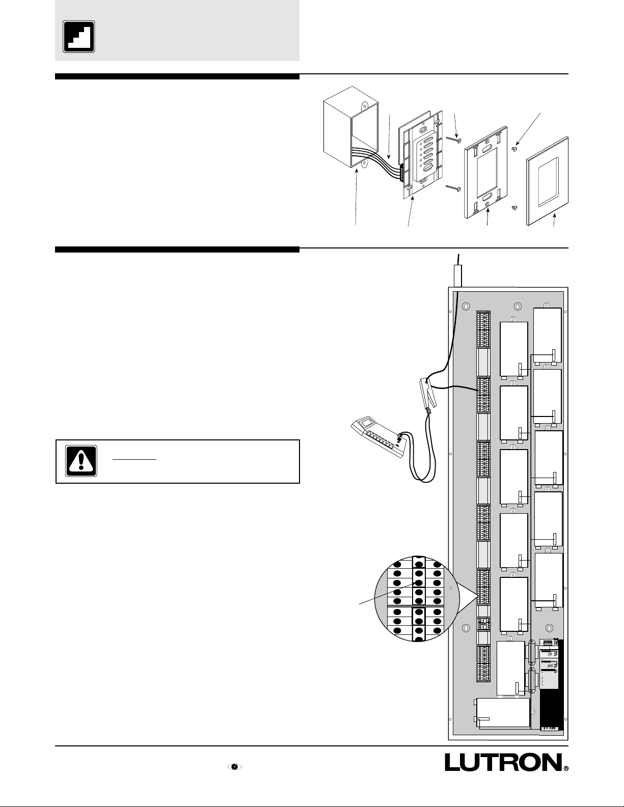
Look Inside an XP
XP Series Switching Panels
The XP Series Switching Panel has 1 to 12 Switching
Modules and a Circuit Selector to set up Zone
Assignments and Load Types.
Each Switching Module has four switching
mechanisms. Each switching mechanism connects
or disconnects 16 Amps max. from Hot to Switched
Hot based on the intensity of its assigned zone of a
GRX-4000 Control Unit.
XP Series Panels are designed to mount between two
studs that are on 16" centers. Each panel may be
mounted in or on a wall.
All XP Series Panels have a Type 1 enclosure, are UL
listed under UL file 42071, and are CSA certified.
TERMINAL BLOCKS FOR
HOT AND SWITCHED HOT
WIRES. THERE ARE 8
TERMINAL BLOCKS PER
SWITCHING MODULE
LOAD WIRING 16A MAX PER
SWITCHING MODULE OUTPUT
NSH
2
4
NH
6
Reference Sheet
SP
XP
1
LED DIAGNOSTIC
1 BLINK/SEC = OK
1 BLINK/7 SEC = NO
3
COMMUNICATION
CONTROL WIRING
PLUG-IN CONNECTOR
(ADDRESSES MODULE)
5
SWITCHING MODULE
(UP TO 12)
DIN RAIL
TERMINAL BLOCKS FOR
A DEDICA TED CONTROL
WIRING FEED
CLASS 2 TRANSFORMER
TO POWER THE
CIRCUIT SELECTOR
AND GRX WIRING
CLASS 2 TRANSFORMER
TO POWER THE MODULES
N
N
H
H
NEUTRAL HOT/LIVE
WIRE WIRE
10
11
12
8
Link Status
S
electCircuit
V
S
S
electValueDisplayed
Load Type
Control and Zone Assigned
Low End Trim(optional)
High End Trim (optional)
Circuit Level
7
9
12345
IEWVALUE
electValue
1 Inc/Mag LV
2 Fluorescent
3 Neon/CC
Using circuit schedule
Using Zone Capture
CONTROL WIRING
HARNESS (CLASS 2)
KEEP POWER WIRES
Power OK (Pins 1,2)
1/4 " AWAY FROM THIS
Data OK (Pins 3,4)
1
HARNESS
2
Circuit
3
4
Value
5
4 Non-dim
5 Elec. LV
_
Unassigned
TM
CIRCUIT SELECTOR
R
LUTRON
R
LUTRON
NORMAL/EMERGENCY
SWITCH TO DEFINE
WHICH PANEL IS
“NORMAL” AND WHICH
IS “EMERGENCY”
20
Reference Sheets for GRAFIK Eye Switching Panel
Page 23

Accessory to Control Unit
to Panel Wiring
Correct Wiring Technique
ACCESSORY
GP
CONTROL
SERIES
PANEL
GRX-4000
Reference Sheet
SERIES
PANEL
1 to 1 Wiring
TO ADDITIONAL
CONTROL UNITS
AND ACCESSORY
CONTROLS
XP
ACCESSORY
CONTROL
ACCESSORY
CONTROL
ACCESSORY
CONTROL
GRX-4000
GRX-4000
TO OTHER PANEL OR GRX-4000 SERIES
CONTROL UNITS OR ACCESSORY
CONTROLS
WIRING MUST BE DAISY-CHAINED, NOT BRANCHED OR HOME RUN.
XP SERIES PANEL
1 2 3 4 5
SHIELD SHIELD
4
3
2
1
ACCESSORY
CONTROL
(16 MAX.)
3
434
OUT
GRX-4000 SERIES CONTROL UNIT
SSARET
IN
(8 MAX.)
Notes:
• Connections are made inside the Accessory
Control’s backbox or in a junction box (provided by
others) located no more than 8 ft. (2.4m) from the
Accessory Control.
• Wiring shown must not be run in the same raceway
as line (mains) voltage wiring.
• Total Control wiring length is not to exceed 2000 ft.
(450m for 220V, 230V or 240V panels).
SSA
2
1
NTGRX-1S
• Panels may be in the middle of a control link.
They do not need to be at an end.
• Shielding must be connected at each junction,
but not earth grounded.
TO ANY NUMBER OF
SINGLE SCENE
ACTIVATORS
Reference Sheets for GRAFIK Eye Switching Panel
21
Page 24

Panel to Panel Wiring
1 to 1 Wiring
TO GRX-4000 SERIES
CONTROL UNITS AND
ACCESSORY CONTROLS
1
Reference Sheet
TO NEXT
XP SERIES PANEL
1
2
SHIELD SHIELD
3
4
1 2 3 4 5
Circuit
Value
4 Non-dim
5 Elec. LV
Power OK (Pins 1,2)
Data OK (Pins 3,4)
1
2
3
4
5
Wire
1
2
3
4
5
Link Status
S
ELECT CIRCUIT
V
IEW VALUE
S
ELECT VALUE
S
ELECT VALUE DISPLAYED
First XP Series Panel
Load Type
1 Inc/Mag LV
2 Fluorescent
Notes:
• The additional #18 AWG (1.0mm2) wire is a ‘sense’
line from terminal 5 of another panel. This sense
line allows an Emergency (Essential) Lighting
Panel to ‘sense’ when Normal (Non-Essential)
power is lost.
If more than one Emergency Lighting Panel needs
to sense off a specific Normal panel, a dedicated
wire may need to be run between each pair of
Normal (Non-Essential) and Emergency (Essential)
panels.
• Shielding must be connected as shown, but do not
connect to Ground (Earth) or Circuit Selector. It is
easiest to connect the bare drain wires and cut off
the outside shield.
Function
Common
24VFW
Mux
Mux
Sense Line
1 2 3 4 5
Circuit
Value
4 Non-dim
5 Elec. LV
Power OK (Pins 1,2)
Data OK (Pins 3,4)
1
2
3
4
5
Link Status
S
ELECT CIRCUIT
V
IEW VALUE
S
ELECT VALUE
S
ELECT VALUE DISPLAYED
Second XP Series Panel
Load Type
1 Inc/Mag LV
2 Fluorescent
2
3
4
5
Reference Sheets for GRAFIK Eye Switching Panel
22
Page 25

Circuit Selector Functions
Circuit Selector Functions
Circuit Selector listens to the GRX-4000 Series
Control Unit(s) and then tells the circuits whether to
be ON or OFF.
It can also be used to select Values for each Circuit:
• Load Type - allows the switch to operate at
specified times:
1,2,3,5 = Do not use for XP series
4 = Non-dim with load turned ON as the GRX
4000 Series Main Unit’s intensity changes
from below 100% to 100% (last ON), and
turned OFF as the intensity goes from
100% to below 100% (first OFF).
6 = Non-dim with load turned ON as the GRX
4000 Series Main Unit’s intensity changes
from 0% to 1% (first ON), and turned OFF
as the intensity goes from 100% to below
100% (first OFF).
– = Unassigned
• Control and Zone Assigned - allows two ways of
assigning a control and zone to a specific circuit.
1) ‘using Circuit Schedule’ see Step 13.
2) ‘
Using Zone Capture TM
Zone to be ‘captured’ by the Circuit Selector by
doing the following:
A. Press and hold buttons 1 and 5 until
lights.
B. Use buttons 1 and 2 to choose the correct
S
ELECT VALUE
circuit to be assigned.
C.Press button 5 repeatedly until
Using Zone CaptureTM
will now flash.
D.Go to the GRX-4000 Series Control Unit to be
assigned to this circuit.
E. Select Scene 1.
F. Identify the zone to be assigned to this circuit.
G.Press the zone button until all zone LEDs
are off.
H.Press the zone button until all zone LEDs
are on.
I. Press the zone button until all zone LED
are off.
(Steps H. and I. must take less than 15 seconds or
the Circuit Selector will not lock on the captured zone.)
J. Go back to the Circuit Selector and the proper
Control and Zone should be displayed.
Repeat this process for any other Circuits.
K. Press and hold buttons 1 and 5 until
VIEW VALUE lights.
• Low and High End Trims - not used.
• Circuit Test Level - See Troubleshooting
Reference section.
’ allows a Control and
lights. The Load
Reference Sheet
‘Power OK’ indicates
whether 24VFW is
present to terminal 2 or
not.
1 2 3 4 5
Link Status
S
ELECT CIRCUIT
V
IEW VALUE
S
ELECT VALUE
S
ELECT VALUE DISPLAYED
Load Type
1 Inc/Mag LV
2 Fluorescent
3 Neon/CC
Control and Zone Assigned
Using circuit schedule
Using Zone Capture
Low End Trim (optional)
High End Trim (optional)
Circuit Level
The Circuit Selector can also provide or receive a ‘sense’
line depending on the location of Switch 6. See Step 16.
‘Data OK’ blinks when
the Circuit Selector is
receiving data from the
GRX-4000 Series Control
Unit(s).
Power OK (Pins 1,2)
Data OK (Pins 3,4)
1
2
Circuit
3
4
Value
5
4 Non-dim
5 Elec. LV
– Unassigned
TM
®
SW6
Reference Sheets for GRAFIK Eye Switching Panel
23
Page 26

Troubleshooting Guide
Troubleshooting Guide
Reference Sheet
Symptom
Normal
Operation as
Reference
All switches
controlled by
1st zone
No control-
Level Frozen
Any accessory
control or
main unit not
responding to
button pushes
LED
Switching
Module
“Heartbeat”
(~1 per sec)
“Heartbeat”
(~1 per sec)
“Light House”
(~1 per 7 sec)
“Light House”
(~1 per 7 sec)
Circuit Selector
‘Power OK’
LED
On
On
On
On
Off
On
On
Off
Link Status
‘Data OK’
LED
Blinking
Blinking
Blinking
Off
Off
Off
Off
Off
Power OK
Data OK
Circuit #
Display
OK
Out
OK
OK
OK
Out
OK
OK
OK
GRX LEDs
OK
OK
OK
OK
OK
Off
Off
OK
Off
Possible Cause/Solutions
• All LEDs show OK, see below for
other suggestions
• Push any button on Circuit Selector
(display turns off in 20 minutes)
• Circuit Selector not Set Up - see
instructions for zone assigning in
Step 13.
• 2 wire link on Control Harness
disconnected at the bottom of the
Circuit Selector
• Invalid Load Type chosen - see step 9
• GRX 4000 control units not addressed
- see instructions in step 10
• Wiring of Terminals 3 and 4 flipped
• GRX connector unplugged at control
unit
• Circuit Selector's Class 2 Transformer
open
• Miswire to control link wires 1,2,3,
and 4
• Miswire to control link wires 3 and 4
• Miswire shorting 24VFW (Terminal 2)
to Common (Terminal 1) or ground
Switching occurs
at the wrong
intensity
Switch stays ON
at all intensities
Out
“Heartbeat”
(~1 per sec)
“Heartbeat”
(~1 per sec)
Off
On
On
On
Off
Blinking
Blinking
Blinking
Out
OK
OK
OK
Off
OK
OK
OK
• Control Feed Breaker Off
• Module Class 2 Transformer open
• Circuit Selector not Set Up for proper
Load Type - see Step 9 and/or Step 1 5
• Relay tack weld - check that load
current is less than 16 Amps. Cycle
relay 10 times from the Circuit
Selector-see next page. If relay
continues to not respond, contact
Lutron for possible replacement.
24
Reference Sheets for GRAFIK Eye Switching Panel
Page 27

Troubleshooting Guide
Troubleshooting Guide (cont.)
After checking LED diagnostics, use this chart:
Reference Sheet
Symptom
Accessory Control will not go into Set Up Mode
Two Control Units have the same Address (usually A1)
Note:
The following voltages should be present on the
GRX wiring:
Terminals 2 to 1 ≈ 22VDC
Terminals 3 to 4 ≈ 3VDC
Terminals 5 to 1 if Switch 6 set for Normal ≈ 22VDC
Other Troubleshooting tools:
The Circuit Selector can be used to view the intensity
information being sent to the switch. Use buttons 1
and 2 on the Circuit Selector to access the circuit
number desired. Press button 5 repeatedly until
Circuit Level lights. Value displayed is now the
present intensity sent from the GRX-4000 Control Unit
controlling that circuit. Value = 0 is OFF, Value = 100
is ON full.
The Circuit Selector can also be used to manually
turn the switch mechanism ON or OFF. Press and
hold buttons 1 and 5 until lights. Use
SELECT VALUE
buttons 1 and 2 to access the circuit desired. Press
button 5 repeatedly until Circuit Level lights.
Buttons 3 and 4 will now control the desired circuit.
Value = 0 is OFF, Value = 100 is ON full, Value = CF
is Circuit Finder - load will cycle ON and OFF.
Note that while in the , Circuit Level
SELECT VALUE
mode, the display will not time out in 20 minutes.
Possible Cause/Solutions
• GRX-4000 Series Control Units are not addressed.
• Terminals 3 and 4 miswired.
• One of the units has wires 3 and 4 crossed or open. Wire terminal 3 to
terminal 3, 4 to 4.
1 2 3 4 5
Circuit
Value
4 Non-dim
5 Elec. LV
– Unassigned
Power OK (Pins 1,2)
Data OK (Pins 3,4)
1
2
3
4
5
TM
®
Link Status
SELECT CIRCUIT
VIEW VALUE
SELECT VALUE
SELECT VALUE DISPLAYED
Load Type
1 Inc/Mag LV
2 Fluorescent
3 Neon/CC
Control and Zone Assigned
Using circuit schedule
Using Zone Capture
Low End Trim (optional)
High End Trim (optional)
Circuit Level
Reference Sheets for GRAFIK Eye Switching Panel
25
Page 28

Circuit Directory
Reference Sheet
Circuit
Location
(Room or
Area)
Customer
Ckt. #
Panel
Ckt. #
C
1
2
3
4
5
6
7
8
9
10
11
12
13
14
15
16
17
18
19
20
21
22
23
24
25
26
27
28
29
30
31
32
33
34
35
36
37
38
39
40
41
42
43
44
45
46
47
48
Circuit
Description
(Fixture Name)
Control Feed-________ Volts
Non-Dim
Load T ype
ON OFF
4 Last First
6 First First
Zone
Assignments
Address Zone
A1-A8 1-8
or G600 Zone #
Actual Load
3 Phase, 4 Wire Shown
Circuit Rating is 16 Amps cont.
1
/3 HP @ 120V, 1/2 HP @ 277V
Phase A
Phase B
Phase C
Reference Sheets for GRAFIK Eye Switching Panel
26
Page 29

Control Directory
Control Directory - GRX-4000 Series Control Units
(8 max/link)
Reference Sheet
Area: Area: Area: Area:
A1
1
A1
2
A1
3
A1
4
A1
5
A1
6
A1
7
A1
8
A5
1
A1
LUTRON
Zone
A2
1
A2
2
A2
3
A2
4
A2
5
A2
6
A2
7
A2
8
Area:Area: Area: Area:
A5
LUTRON
Zone
1
A6
Zone DescriptionZone Description Zone DescriptionZone
LUTRON
Zone DescriptionZone Description Zone DescriptionZone
A2
A6
Zone
A3
A3
A3
A3
A3
A3
A3
A3
Zone
A7
1
2
3
4
5
6
7
8
1
A3 A4
Zone
A4
A4
A4
A4
A4
A4
A4
A4
A7 A8
LUTRON LUTRON
Zone
A8
LUTRONLUTRONLUTRON
Zone Description
1
2
3
4
5
6
7
8
Zone Description
1
A5
A5
A5
A5
A5
A5
A5
2
3
4
5
6
7
8
A6
A6
A6
A6
A6
A6
A6
2
3
4
5
6
7
8
Use this Directory as GRX-4000 Series Control Units
are addressed and zones are assigned. Keep this
Directory for job records and maintenance
information.
A7
A7
A7
A7
A7
A7
A7
2
3
4
5
6
7
8
A8
A8
A8
A8
A8
A8
A8
2
3
4
5
6
7
8
Reference Sheets for GRAFIK Eye Switching Panel
27
Page 30

Maintenance
Maintenance
Reference Sheet
XP Series Panels
Danger - Any liquid entering the panel
may reach internal components, cause
personal injury, damage the equipment,
and void the warranty.
1. If any extra wiring is brought into the panel,
temporarily cover the modules and thoroughly
remove all metal chips, wire strands, insulation,
or other debris before reapplying power.
2. In the unlikely event of damage to switching
equipment, replace bypass jumpers (see step 11).
This will take the switching equipment out of the
circuit and apply full power to fixtures.
3. To take manual control of the On or Off state of any
circuit, use the Circuit Selector (see Troubleshooting
Guide).
4. The exterior of the XP Panel may be painted as
follows:
a. Remove the front cover.
b. Cut a piece of paper slightly smaller than the
cover label (label is 7" x 2.675" with rounded
corners)
c. Tape the cut paper onto the label so that the tape
holds the paper and completely covers the
label. Avoid taping any of the label except the
outside edge.
d. For the cover or painted enclosure, sand the
existing paint to roughen it. For galvanized
enclosure - wipe the outside (do not paint the
inside) surface with a damp, soapy cloth.
e. Paint the cover or enclosure exterior. For
galvanized enclosure, use an acrylic (OVM
recommended) or urethane paint - not an oil
based paint.
Warning - When painting the panel cover,
keep all vent holes open and clear of any
paint pooling.
Danger - Turn power off before working on
any load. Each circuit may have an
individual, external disconnect switch.
Locate and lock the appropriate
disconnect switch (usually a breaker)
before servicing.
Warning - When working on any load
(such as rewiring a load), replace the
bypass jumpers to protect the switching
module until the load is proven.
GRX-4000 Series Control Units and Accessory
Controls
Clean front surface of control with a soft towel
moistened with a mild soap solution (nonammonia- based). Clean approximately every six
months.
Caution - Do not spray cleaning solution
onto control as it may reach internal
components.
Fixtures
It is important that lamps are maintained properly to
prevent what may appear as switching equipment
malfunctions. When lamps begin to fail on a circuit,
Lutron recommends group relamping of the entire
circuit.
28
Reference Sheets for GRAFIK Eye Switching Panel
Page 31

Glossary of Terms
Glossary of Terms
Reference Sheet
e
e
s
s
d
d
o
o
p
p
p
p
t
t
o
o
u
u
s
s
l
l
o
o
s
s
i
i
o
o
k
k
s
s
i
i
l
l
h
h
i
i
t
t
k
k
,
,
e
e
t
t
a
a
o
o
n
n
d
r
o
eit
v
e
i
l
e
B
a
w
on
c
i
s
i
h
T
r
o
eit
v
e
i
l
e
B
a
w
on
c
i
s
i
h
T
r
i
d
the
r
e
d
n
u
a
w
on
c
i
s
i
h
T
r
o
eit
v
e
i
l
e
B
a
w
on
c
i
s
i
h
T
d
r
i
i
c
c
o
t
ti
i
o
o
n
n
eit
a
a
v
r
r
y
y
e
i
!
!
l
e
t
t
M
M
n
n
e
e
r
r
.
.
B
B
N
N
y
y
y
y
b
b
e
e
,
,
B
d
d
J
J
e
e
t
t
u
u
a
a
l
l
y
y
e
e
r
r
6
6
c
c
,
,
s
s
1
1
a
9
9
9
9
w
5
5
.
.
on
c
i
s
i
e
e
s
s
d
d
o
o
p
p
p
p
t
t
o
o
u
u
s
s
l
l
h
o
o
s
s
o
o
i
i
k
k
s
s
i
i
l
l
h
h
i
i
T
t
t
k
k
,
,
e
e
t
t
a
a
o
o
n
n
d
d
r
i
i
c
c
o
t
t
i
io
o
n
n
eit
a
a
v
r
r
y
y
e
i
!
!
l
e
t
t
M
M
n
n
e
e
r
r
.
.
B
B
N
N
y
y
y
y
b
b
e
e
,
,
B
d
d
J
J
e
e
t
t
u
u
a
a
l
l
y
y
e
e
r
r
6
6
c
c
,
,
s
s
1
1
a
9
9
9
9
w
5
5
,
.
on
c
i
s
i
h
.
.
T
T
R
R
k
k
h
h
e
e
o
o
r
r
m
m
e
e
T
D
D
a
a
s
s
f
f
.
.
o
o
n
n
o
o
i
i
t
t
c
c
e
e
r
i
d
the
r
e
d
n
t
t
M
M
n
n
e
e
r
r
.
.
N
N
B
B
y
y
y
y
b
b
e
e
,
,
u
d
d
J
J
e
e
t
t
u
u
a
a
l
l
y
y
e
e
r
r
6
6
c
c
,
,
s
s
1
1
a
9
9
9
9
w
5
5
.
.
on
c
i
s
i
e
e
s
s
d
d
o
o
p
p
p
p
t
t
o
o
u
u
s
s
l
lo
h
o
s
s
i
i
o
o
k
k
s
s
i
i
l
l
h
h
i
i
T
k
k
t
t
,
,
e
e
t
t
a
a
o
o
n
n
d
d
r
i
i
c
c
o
t
ti
i
o
o
n
n
eit
a
a
v
r
r
y
y
e
i
!
!
l
e
t
t
M
M
n
n
e
e
r
r
.
.
N
N
B
B
y
y
y
y
b
b
e
e
,
,
B
d
d
J
J
e
e
t
t
u
u
a
a
l
l
y
y
e
e
r
r
6
6
c
c
,
,
s
s
1
1
a
9
9
9
9
w
5
5
.
.
on
c
i
s
i
h
T
Accessory Control - GRAFIK Eye control wired to a
GRX-4000 (or GRX-3000) Series Control Unit to
select scenes, raise and lower specific zones or
other functions on an attached Control Unit.
Addressing - a way for the controls on a link to
identify each other. Accessory Controls are
addressed from the back, using switches 1 through
4 on the back of each control. Each control needs
a unique address, GRX-4000 Series Control Units
are addressed while in Set-Up Mode from the front
panel’s buttons.
Circuit Selector - the interface between the GRX-
4000 Series Control Units and the Switching
Modules that reside in an XP panel. The Circuit
Selector houses all Circuit Values including Load
Type and Control and Zone assigned.
Control Link - the daisy-chained link of controls
powered by the XP Panel. A maximum of 8 GRX4000’s and 16 Accessory Controls may be wired
together to form a link (any number of NTGRX-1S’s
can be used in the SSA terminal).
Fade - a gradual change in zone intensity in a room
or space.
Fade Time - Selected time interval to change from
one scene to another. A GRX-4000 (and GRX-
3000) Series Control Unit has a customer-settable
fade time that ranges from 0-59 seconds and 1 to
60 minutes.
GRX-4000 Series Control Unit - a control on the
control link that allows zone intensities to be set for
up to 16 scenes. Control Units are available in 2,
3, 4, 6, and 8 Zone varieties.
Job - name of a location where GP, LP or XP Series
Panels and GRX-4000 Series Control Units are
being/have been installed.
LED (Light Emitting Diode) - an illuminated indicator
to help in setting up and diagnosing XP Panel and
GRX-4000 Series Control Unit’s functions.
Load Type - a value in the Circuit Selector that
defines the performance of the circuit to optimally
control the following: 1) Incandescent, 2) Hi-lume
FDB or Eco-10 Dimmable Fluorescent, 3) Neon, 4)
Non-Dim, 5) Electronic Low Voltage, and 6)
Screen Non-Dim. Only Load Types 4) and 6) are
valid in an XP Series Panel.
Non-Dim Load - a source that is not to be dimmed.
Load Type for that circuit is to be set to Load Type
4 or 6 only. In an XP Series Panel, all loads are
Non-Dim loads.
Scene - (or Preset) - Predetermined light intensity for
one or more lights, creating a lighting effect that
can be recalled by pressing a single button. The
GRX-4000 Series Control Unit has Scene 1-4 and
OFF accessible on the front of the control. Some
Accessory Controls can be Set-Up to access
Scenes 5-16.
SM - Switching Module - a group of up to 4 switching
mechanisms in a module which can each switch up
to 16 Amps of various load types.
SSA - Single Scene Activator (model # NTGRX-1S)
alternately toggles the GRX-4000 (or GRX-3000)
Series Control Unit to which it is wired between
Scene 1 and OFF. This control is not counted as
an Accessory Control and multiple SSA controls
can be wired in parallel controlling the same
GRX-4000. Usually used for Entrances.
XP Series Panel - Switching Panel - includes 1 to 12
Switching Modules (SM’s) which will switch 4 16A
loads each.
Zone - a fixture or a group of fixtures controlled
simultaneously. The GRX-4000 Series Control Unit
controls multiple zones (e.g. a GRX-4108 can
control 8 zones). Each zone can be assigned to
one or more Circuits in a XP Panel. Each zone
should only control one Load Type.
Zone Capture TM
- a method of Assigning a Control
and Zone to a circuit without knowing Control
Addresses. See ‘Circuit Selector Functions’ in the
Reference Section.
Reference Sheets for GRAFIK Eye Switching Panel
29
Page 32

Warranty
Warranty
Lutron warrants each new unit, for a period of one
year from the date of shipment, to be free from
defects in materials or workmanship under conditions
of normal use and specified ambient temperature
when installed and operated under Lutron product
specifications and in accordance with the applicable
National Electrical Code and Safety Standards of
Underwriters Laboratories. Lutron shall, at its option,
repair or replace any defective unit which, in its
opinion, has not been improperly installed, wired,
insulated, used or maintained, provided, however,
that Lutron shall not be required to remove, install or
reinstall any defective unit and provided that Lutron
is promptly notified of said defect within the
aforementioned warranty period. The foregoing
warranty and optional remedies are exclusive and,
except for the foregoing warranties, THERE ARE
NO EXPRESS IMPLIED WARRANTIES OF
MERCHANTABILITY NOR OF ANY OTHER TYPE.
In no event shall Lutron or any other seller be liable
for consequential or special damages, nor for any
repair work undertaken without its prior written
consent, nor shall Lutron’s liability on any claim for
damages arising out of or connected with the
manufacture, sale, installation, delivery or use of said
unit ever exceed the price paid therefor.
These products may be covered by one of more
of the following U.S. patents: 4,797,599;4,803,380;
4,825,075; 4,893,062; 4,954,768; 5,030,893; 5,038,081;
5,191,265; 5,309,068; 5,430,356; 5,463,286; DES
308,647; DES 310,349; DES 311,170; DES 311,382;
DES 311,485; DES 311,678; DES 313,738; DES
335,867; DES 344,068; DES 344,264; and
corresponding foreign patents. Other U.S. and
foreign patents may be pending.
Lutron, GRAFIK Eye and Hi-lume are registered
trademarks; Eco-10, Zone Capture , and Architrave
are trademarks of Lutron Electronics Co., Inc.
Technical and Sales Assistance
World Headquarters
Lutron Electronics Co., Inc.
7200 Suter Road
Coopersburg, PA 18036-1299 U.S.A.
TOLL FREE: (800) 523-9466 (U.S.A., Canada, and
the Caribbean)
Tel: (610) 282-3800; International 1610 282-3800
Fax: (610) 282-3090 International 1610 282-3090
European Headquarters
Lutron EA LTD
Lutron House
6 Sovereign Close
Wapping
London, E1 9HW England
FREEPHONE: 0800 282107 (U.K.)
Tel: (0171) 702-0657; International 44171 702-0657
Fax: (0171) 480-6899; International 44171 480-6899
UAE, Dubai Sales Office
Tel/Fax: 04-440-206; International 971-4-440-206
Asian Headquarters
Lutron Asuka Corporation K.K.
3rd Floor
Madre Matsuda Bldg.
4-13, Kioi-cho;
Chiyoda-Ku, Tokyo 102 Japan
TOLL FREE: (0120) 083417 (Japan)
Tel: (03) 3234-1486; International 81 3 3234-1486
Fax: (03) 3234-0167; International 81 3 3234-0167
Hong Kong Sales Office
Tel: 2593-1119; International 852-2-593-1119
Fax: 2593-1197; International 852-2-593-1197
If you have questions concerning the installation or
operation of this product, call the toll-free
Hotline
(800) 523-9466 (U.S.A., Canada, and the Caribbean)
(610) 282-3800 (Other areas)
Our address on the web is http://www.lutron.com
Lutron Electronics Co., Inc., reserves the right to
make improvements or changes in its products
without prior notice. Although every attempt is made
to ensure that this information is accurate and up to
date, please check with Lutron to confirm product
availability, latest specifications and suitability for your
application.
1996 Lutron Electronics Co., Inc.
MADE AND PRINTED IN U.S.A.
30
P/N 032-052 8/96 Rev A
:
Lutron
 Loading...