

Page 1
Installation and Operation Instructions
Occupant Copy
GBO-RS232 Interface Control
Class 2/PELV Device
Description
The GBO-RS232 Interface allows up to 8 GRAFIK Eye Control
Units to be interfaced with your Bang & Olufsen
®
Avant
™
Television. The GBO-RS232 enables your Home Theater to
execute “ON” & “OFF” commands.
Note: Only one GBO-RS232 can be installed on the same
MUX Link.
Features
The GBO-RS232 can send RS232 commands from the Bang
& Olufsen Avant Television to a maximum of 8 GRAFIK Eye
Bang & Olufsen Series Control Units. The following com-
mands are available:
Home Theater “ON”. The Avant Television turns [OFF]
and the projection system turns [ON]. This scene is predefined on the GRAFIK Eye Control Unit as scene 14.
Home Theater “OFF”. The Avant Television turns [ON]
and the projection system turns [OFF]. This scene is predefined on the GRAFIK Eye Control Unit as scene 13.
MUX LINK
1 2 3 4
1 2 3 4 5 6 7 8
LED1 LED2
1
PROGRAMMING INTERFACE
AUXILIARY CONTROL
GBO-RS232
COOPERSBURG, PA 18036
R
GRAFIK Eye 3000 Series
FOR WIRING OF 4000 SERIES, REFER
TO INSTALLATION INSTRUCTIONS
1 2 3 4
MUX LINK
1 2 3 4 5
RS232 LINK
Avant™ TELEVISION
RxD
TxD
COM
HOT/LIVE
SSA
Zone 3
Zone 2
Zone 1
CU WIRE ONLY
Neutral
Class 2
4
3
2
1
PELV (CLASS 2:USA)
R
2345
TO AVANT
TELEVISION
TO GRAFIK
EYE
MUX LINK RS232 LINK
1 2 3 4 5
1 2 3 4
COM
+V
MUX
COM
DATA
IN
DATA
OUT
MUX
N/C
N/C
POWER INPUTS:
MUX LINK 2 (+V): 12 (3000 SERIES)
MUX LINK 2 (+V): 24 (4000 SERIES)
For use with Bang and Olufsen®
systems only.
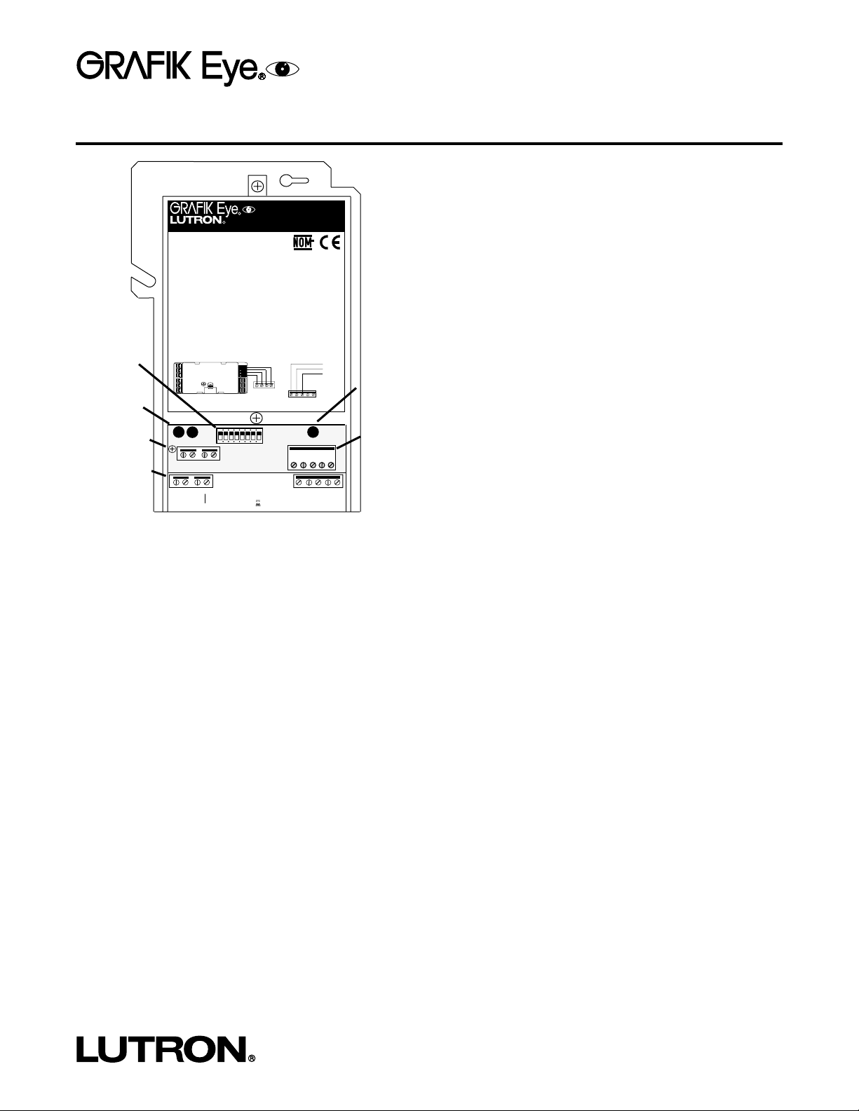
GBO-RS232 (shown with cover removed)
DIP Switches
Output Status
LEDs
Ground Screw
MUX Link to
GRAFIK Eye
Control Units and
Accesory Controls
TX Data LED
(LED 3)
RS232 Link
(to Avant
Television)
Page 2
2
Installation
HOT/LIVE
SSA
Zone 3
Zone 2
Zone 1
CU WIRE ONLY
Neutral
Class 2
4
3
2
1
1 2 3 4 5
GROUND
GREEN
BROWN
1 2 3 4
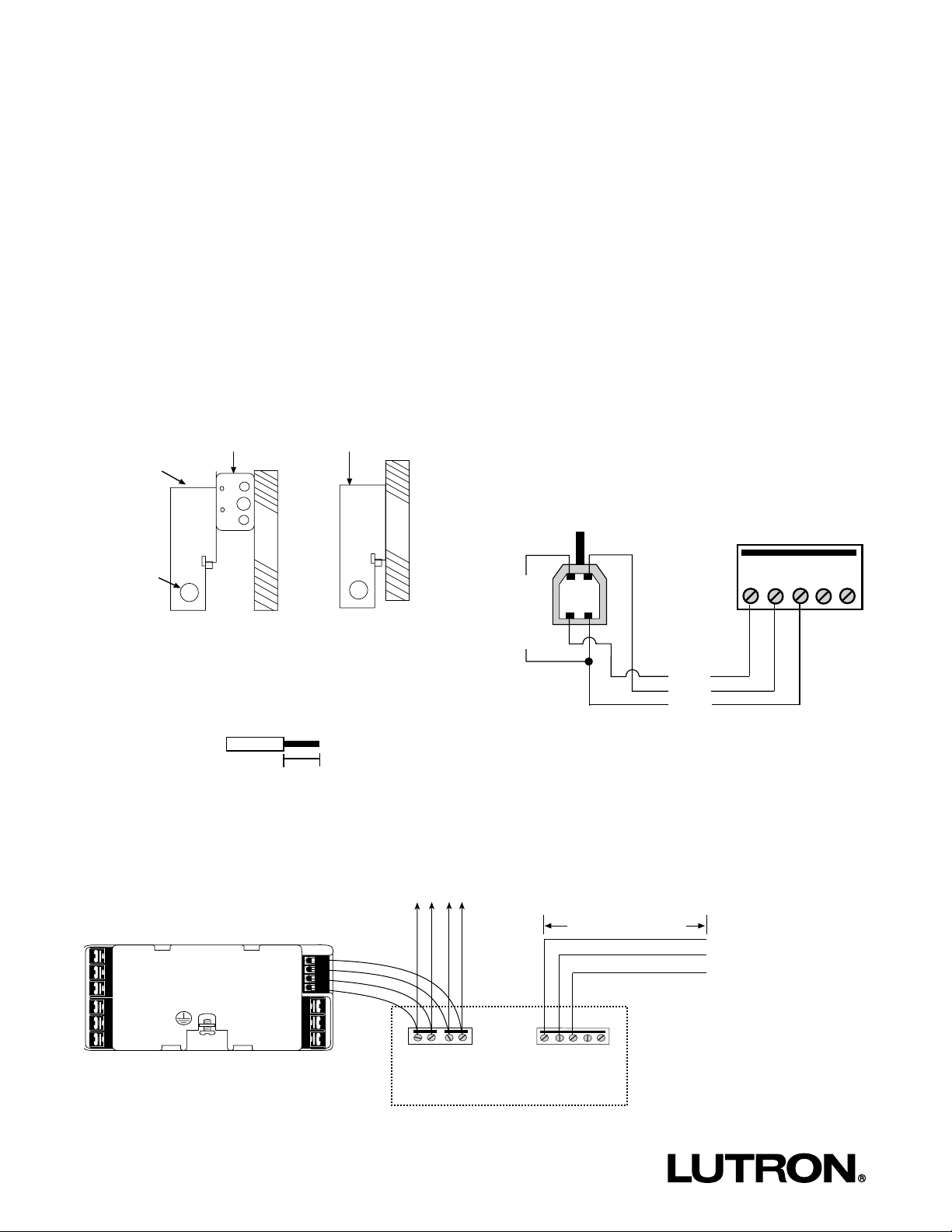
Mounting
1. Mount the GBO-RS232 on a 4"x 4" junction box or directly
on a wall as shown in the Mounting Diagram. If metal conduit is not being used, ensure proper earth/grounding of the
metal casing by connecting an earth/ground wire to the
earth/ground screw. Remove front enclosure cover to expose
terminal blocks, DIP switches, and output status LEDs.
Wiring Diagram
Important Notes
■ Install in accordance with all applicable regulations.
■ Do not connect line voltage/mains power to device. Improper wiring can result in personal injury or damage to the device or to
other equipment.
■ This control can use Class 2/PELV wiring methods. Check with your local electrical inspector for compliance with national and
local codes and wiring practices.
3/8 in. (10 mm)
2. Strip 3/8 in. (10 mm) of insulation from wires. Each terminal
will accept up to two #18 AWG (1.0 mm2) wires.
3. Connect wiring as shown in the Wiring Diagram. LED 1
will be lit when the MUX Link is properly installed.
Wires should be inserted through the circular punchouts in the white metal enclosure so that the enclosure
cover can be replaced after installation.
4. Wiring to your Avant Television. For the RS232
Link, use the cable provided with the Avant Television,
Bang & Olufsen 4-pin USB cable (P/N 6270788). Wire
as shown below.
To up to 7 more GRAFIK Eye Control Units and 15 Wallstations
33 ft. (10 m) Maximum
(B&O 4-Pin USB Cable)
MUX LINK
RS232 LINK
Avant
Television
GBO-RS232 WIRING TERMINALS
Mounting Diagram
GBO-RS232
4” x 4”
Junction Box
GBO-RS232
Insert Wires
Through
Punch-Outs
W
A
L
L
W
A
L
L
5. Addressing GRAFIK Eye Control Units. Control
Units and Wallstations must be uniquely addressed for
use with the GBO-RS232. For addressing, see the
GRAFIK Eye Installer's Guide included with the Control
Units.
GROUND
GREEN
BROWN
Y
E
L
L
O
W
BANG & OLUFSEN
4-PIN USB CABLE
RS232 LINK
1
2
34
1 2345
Page 3

3
DIP Switches
The DIP switches determine which GRAFIK Eye Control Unit(s) the GBO-RS232 will communicate with.
When:
Dip Switch 1 is “ON”- Unit will communicate with the GRAFIK Eye Control Unit addressed “A1”.
Dip Switch 2 is “ON”- Unit will communicate with the GRAFIK Eye Control Unit addressed “A2”.
Dip Switch 3 is “ON”- Unit will communicate with the GRAFIK Eye Control Unit addressed “A3”.
Dip Switch 4 is “ON”- Unit will communicate with the GRAFIK Eye Control Unit addressed “A4”.
Dip Switch 5 is “ON”- Unit will communicate with the GRAFIK Eye Control Unit addressed “A5”.
Dip Switch 6 is “ON”- Unit will communicate with the GRAFIK Eye Control Unit addressed “A6”.
Dip Switch 7 is “ON”- Unit will communicate with the GRAFIK Eye Control Unit addressed “A7”.
Dip Switch 8 is “ON”- Unit will communicate with the GRAFIK Eye Control Unit addressed “A8”.
Note: The GBO-RS232 allows communication with up to 8 Grafik Eye Control Units.
Example:
In this example, DIP switches 1, 3, 4 and 7 are in the [ON] position. DIP switches 2, 5, 6 and 8 are in the [OFF] position. The
GBO-RS232 will communicate with GRAFIK Eye Control Units addressed A1, A3, A4, and A7.
“OFF” Position
“ON” Position
1 2 3 4 5 6 7 8
Page 4

Lutron Electronics Co., Inc.
Made and printed in U.S.A.
P/N 030-685 Rev. A 10/00
LIMITED WARRANTY
Lutron will, at its option, repair or replace any unit that is defective in materials or
manufacture within one year after purchase. For warranty service, return unit to
place of purchase or mail to Lutron at 7200 Suter Rd., Coopersburg, PA 180361299, postage pre-paid.
This warranty is in lieu of all other express
warranties, and the implied warranty of merchantability is
limited to one year from purchase. This warranty does not
cover the cost of installation, removal or reinstallation, or
damage resulting from misuse, abuse, or improper or incorrect repair, or damage from improper wiring or installation.
This warranty does not cover incidental or consequential
damages. Lutron’s liability on any claim for damages arising
out of or in connection with the manufacture, sale, installation, delivery, or use of the unit shall never exceed the purchase price of the unit.
This warranty gives you specific legal rights, and
you may also have other rights which vary from state to state. Some states do not
allow limitations on how long an implied warranty lasts, so the above limitation
may not apply to you. Some states do not allow the exclusion or limitation of
incidental or consequential damages, so the above limitation or exclusion may
not apply to you. This product may be covered by one or more of the following
U.S. patents: 4,797,599; 4,893,062; 5,030,893; 5,191,265; 5,430,356; 5,463,286;
5,530,332; 5,949,200; 5,990,635; DES 311,170; DES 311,371; DES 311,382; DES
311,485; DES 311,678; DES 313,738; DES 335,867; DES 344,068; DES 344,264;
DES 370,663; DES 378,814; DES 387,736; DES 412,315; DES 412,491 and corresponding foreign patents. U.S. and foreign patents pending.
Lutron and GRAFIK Eye are registered trademarks of Lutron Electronics Co., Inc.
Bang & Olufsen is a registered trademark and Avant is a trademark of Bang &
Olufsen Holding A/S.
© 2000 Lutron Electronics Co., Inc.
Internet: www.lutron.com
E-mail: product@lutron.com
WORLD HEADQUARTERS
Lutron Electronics Co., Inc.
TOLL FREE: (800) 523-9466
(U.S.A., Canada, Caribbean)
Tel: (610) 282-3800;
International 1-610-282-3800
Fax: (610) 282-3090;
GREAT BRITAIN
Lutron EA Ltd.,
Tel: (171) 702-0657;
International 44-207-702-0657
Fax: (171) 480-6899; I
nternational 44-207-480-6899
GERMANY
Lutron Electronics GmbH
Tel: (309) 710-4590;
International 49 309 710-4590
Fax: (309) 710-4591;
International 49 309 710-4591
ASIAN HEADQUARTERS
Lutron Asuka Corporation
Tel: (03) 5405-7333;
International 81-3-5405-7333
Fax: (03) 5405-7496;
International 81-3-5405-7496
HONG KONG SALES OFFICE
Lutron GL (Hong Kong)
Tel: 2104-7733;
International 852-2104-7733
Fax: 2104-7633;
International 852-2104-7633
SINGAPORE
Lutron GL (Singapore)
Tel: 65 220 4666; Fax: 65 220 4333
RS232 Operation
The unit will communicate between an Avant Television and a GRAFIK Eye GBO Series Control Unit in a full duplex manner at
9600 baud.
It will understand the following RS232 commands:
:ON<LF> = Command will select scene 13 on the Control Unit addresses that correspond to the DIP switches
that are in the [ON] position.
Note: <LF> = $0A
:OFF<LF> = Command will select scene 14 on the Control Unit addresses that correspond to the
DIP switches that are in the [ON] position.
These comands are then acknowledged on the RS232 link as either ~on<LF> or ~off<LF>.
It also listens to scene selects on the GRX link that come from both control and wallstation units. If it hears a scene select of a
Home Theater scene (scene 13 or 14) that is going to a Control Unit whose address matches an [ON] DIP switch, it will issue a
command out of the RS232 port.
SCENE 13 produces: ON<LF>
SCENE 14 produces: OFF<LF>
The Avant Television has two seconds to send back the appropriate acknowledgement, or the message will be repeated two more
times, each having a two-second acknowledgement period. If there is no acknowledgement after three messages, the unit will give
up. A different message can be sent to the RS232 device before an acknowledgement is received. In this case, the first
message will not require an acknowledgement and will NOT repeat.
 Loading...