

Page 1
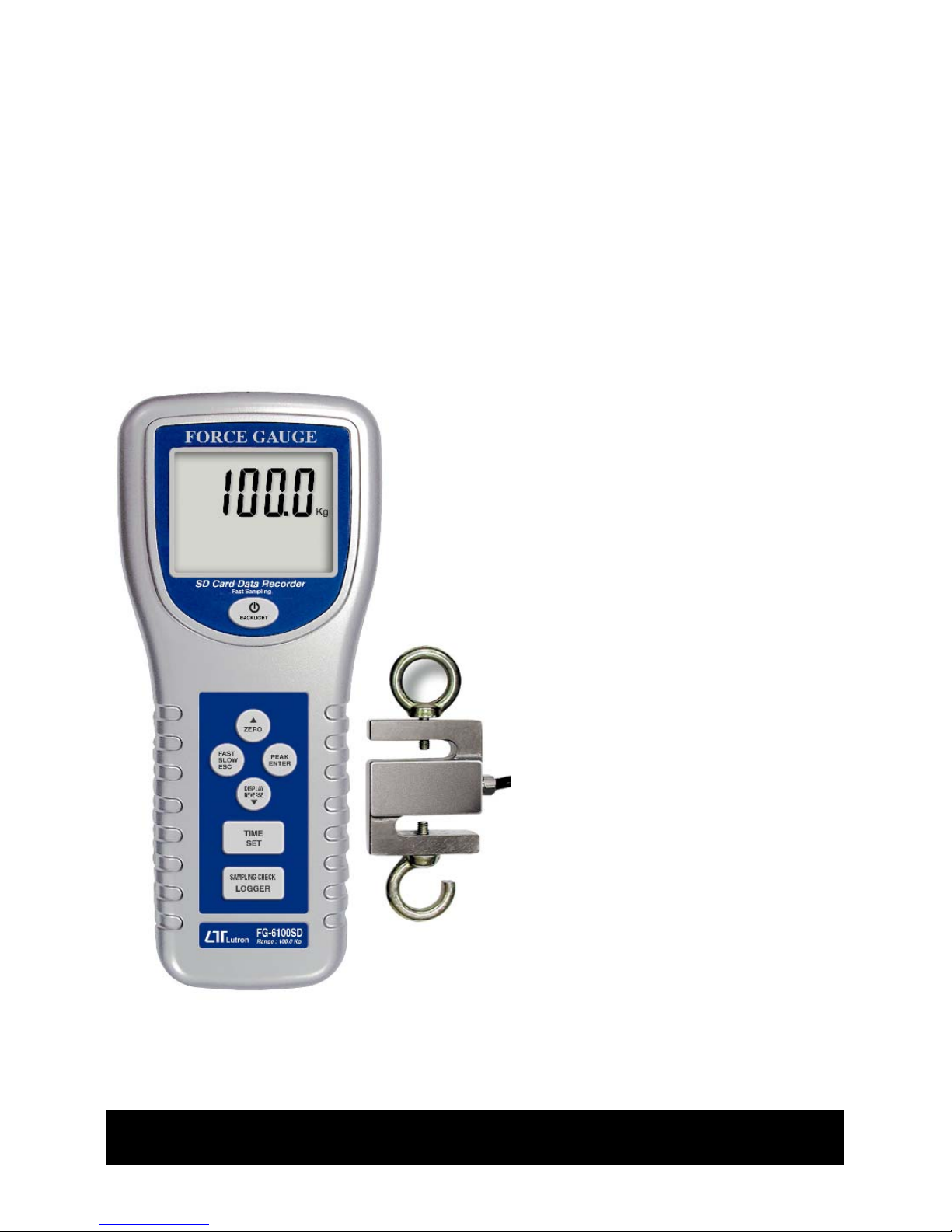
100 Kg
SD Card real time recorder
10 ms sampling time recorder
FORCE GAUGE
Model : FG-6100SD
Your purchase of this
FORCE GAUGE marks a
step forward for you
into the field of precision
measurement. Although
this FORCE GAUGE is a
complex and delicate
instrument, its durable
structure will allow many
years of use if proper
operating techniques are
developed. Please read
the following instructions
carefully and always keep
this manual within easy
reach.
OPERATION MANUAL
Page 2

TABLE OF CONTENTS
1 FEATURES...................................................................1
2 SPECIFICATIONS........................................................
.
2
3 FRONT PANEL DESCRIPTIONS .................................... 6
3-1 Sensor Input socket...............................................6
3-2 LCD Display......................................................... 6
3-3 Power/BACKLIGHT Button......................................6
3-4 /ZERO Button....................................................
.
▲ 6
3-5 FAST/SLOW/ESC Button.........................................6
3-6 PEAK/ENTER Button..............................................
.
6
3-7 DISPLAY REVERSE/ Button.................................
.
▼ 6
3-8 TIME/SET Button...................................................6
3-9 LOGGER/SAMPLING CHECK Button.........................6
3-10 RS-232 output terminal........................................6
3-11 Reset terminal.....................................................6
3-12 DC 9V Power Adapter Input Socket.......................6
3-13 Mounting Holes/fixing Screws...............................6
3-14 Battery Cover/Compartment.................................6
3-15 Sensor Hooks......................................................
.
6
3-16 Sensor ( force sensor ).........................................6
3-17 Sensor plug.........................................................6
3-18 SD card socket....................................................
.
6
4 MEASURING PROCEDURE ........................................... 8
4-1 Pay attention for the measurement........................8
4-2 Normal Measurement ..........................................
.
9
4-3 Peak Hold Measurement ......................................
.
10
4-4 LCD Back light On/Off...........................................11
4-5 Alarm beeper.......................................................
.
11
Page 3

5. DATALOGGER.............................................................11
5-1 Preparation before execute datalogger function.......11
5-2 Normal record mode
Auto Datalogger ( Set sampling time 1 second ).............≧ 12
5-3 Normal record mode
Manual Datalogger ( Set sampling time = 0 second ).........13
5-4 Peak hold record mode
Fast Datalogger...............................................................14
5-5 Check time information..........................................15
5-6 Check sampling time information............................15
5-7 SD Card Data structure..........................................15
6. Saving data from the SD card to the computer.............
.
17
7. ADVANCED SETTING..................................................
.
19
8. POWER SUPPLY from DC ADAPTER..............................25
9. BATTERY REPLACEMENT.............................................25
10. SYSTEM RESET.........................................................25
11. RS232 PC SERIAL INTERFACE....................................26
12. MOUNTING HOLES & OPTIONAL TEST STAND............27
13. APPLICATIONS.........................................................
.
28
Page 4

1. FEATURES
* Data record mode : Normal model or Peak hold mode.
* Normal record mode :
Set sampling time from 1 second to 8 hours.
* Peak hold record mode :
Set sampling time from 10 ms to 500 ms.
* Memory capacity of normal record mode : 1 GB to 16 GB.
* Memory capacity of peak hold record mode :
1000 data no. ( max. )
* Under Peak hold record mode, if execute the " Data
record " function, the memory circuit will store 1000
data no. ( max. ) measuring data into the SD card per
fast speed sampling time ( 10 ms to 500 ms ).
* Under Normal record mode, if execute the " Data record
" function, will save the measuring data along the real
time value ( Year/Month/ Date/Hour/Minute/Second )
into the SD card per normal sampling time ( 1 second
to 8 hours ).
* After save the data into the SD memory card, it can be
down load the data to the Excel directly, extra software
is no need. User can make the further data analysis (
graphic analysis ) by themselves.
* Large LCD display with back light.
* 100 Kg, wide capacity, high resolution, high accuracy,
high repeatability.
* 3 kind display unit : Kg, lb, Newton.
* Tension & compression capability .
* Peak hold ( Max. load ) can be held in display during
make tension or compression measurement.
* Zero button can operate both for normal measuring
& the " peak hold " operation.
* Full capacity zero (tare) control capability.
* Fast/Slow response time push button.
1
Page 5
* Positive or reverse display direction select.
* Hand held & stand mounted gauges are available.
* Low power consumption gives long battery life.
* Build in low battery indicator.
* Microprocessor circuit & exclusive load cell
transducer.
* Over load protection.
* RS-232 computer interface
* Built-in DC 9V power adapter input socket.
* Professional test stand ( optional ).
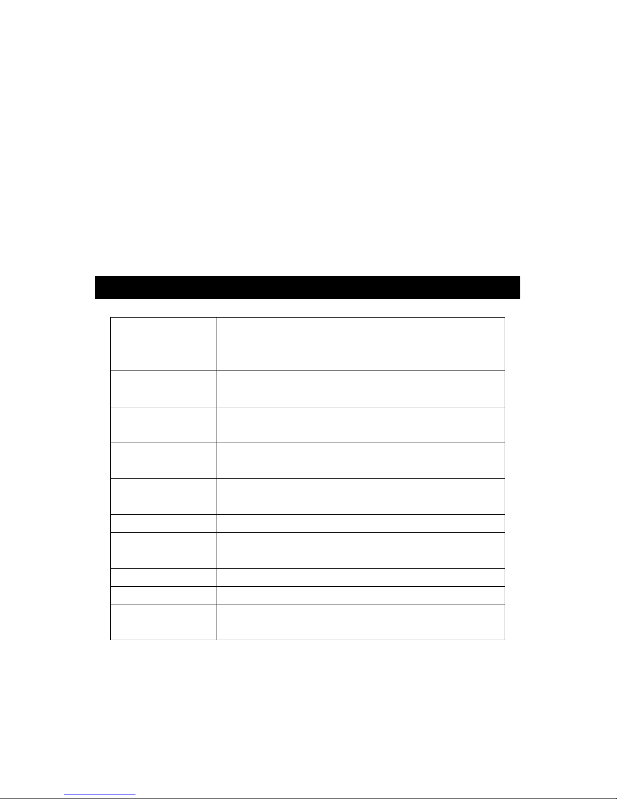
2. SPECIFICATIONS
Display LCD ( Liquid crystal display ).
5 digits, 16 mm ( 0.63" ) digit size.
Back light.
Display Positive or Reverse direction, select by
Direction the push button on the front panel.
Function Tension & Compression (Push & Pull).
Normal force, Peak hold ( Max. load ).
Peak hold Will freeze the display value of the
Peak load ( Max. load ).
Zero Zero button can be operated both for
"normal force" or "peak hold" operation
Unit select Kg, lb, Newton.
Measure 100 Kg/220.5 lb/980.6 Newton.
Capacity
Resolution 0.02 Kg/0.02 lb/0.2 Newton.
Min. Display 0.15 Kg/0.35 lb/1.4 Newton.
Accuracy ± (0.5 % + 0.1 Kg), within 23± 5 .℃
* Under the test weight on 100 Kg & 10 Kg.
2
Page 6
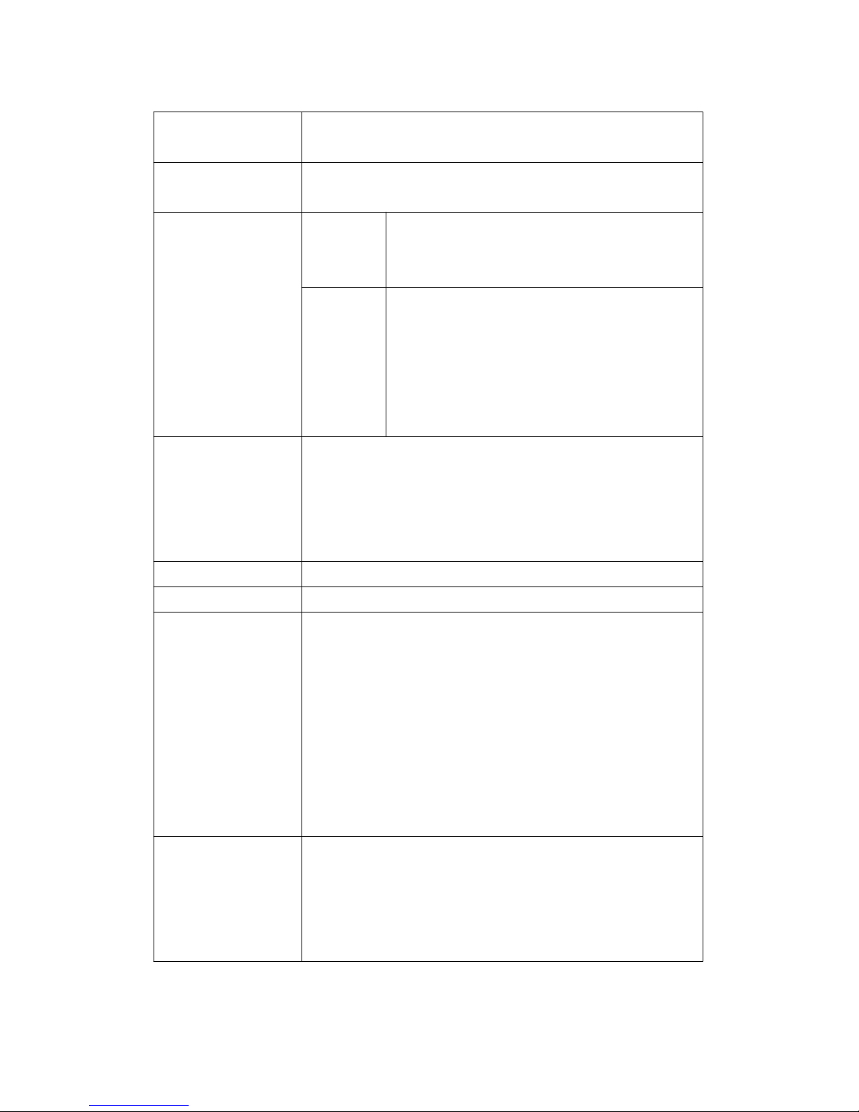
Update time Fast Approx. 0.2 second.
Slow Approx. 0.6 second.
Over range Display show " - - - - " when in over
Indicator range status.
Normal data Auto 1 sec to 8 hour 59 min. 59 sec.
record mode data
@ Sampling time can set to 1 second,
logger
but memory data may loss.
Sampling Time Manual Push the data logger button
Setting range data once will save data one time.
logger
@ Set the sampling time to
0 second.
@ Manual mode, can also select the
1 to 99 position ( Location ) no.
Peak hold 10 mS to 500 mS.
data record
* Each setting step is 10 mS.
mode
* Auto data logger
Sampling Time
* The memory circuit will store 1000
Setting range
data no. ( max. ) measuring data.
Data error no. 0.1% of total saved data max.
Memory Card SD memory card. 1 GB to 16 GB.
Advanced * SD memory card Format
setting * Set clock time ( Year/Month/Date,
Hour/Minute/Second )
* Set sampling time ( normal data record mode )
* Set sampling time ( peak hold data record mode)
* Auto power OFF management
* Unit setting
* Set beep Sound ON/OFF
* Decimal point of SD card setting
Data output RS 232/USB PC computer interface.
* Connect the optional RS232 cable
UPCB-02 will get the RS232 plug.
* Connect the optional USB cable
USB-01 will get the USB plug.
3
Page 7
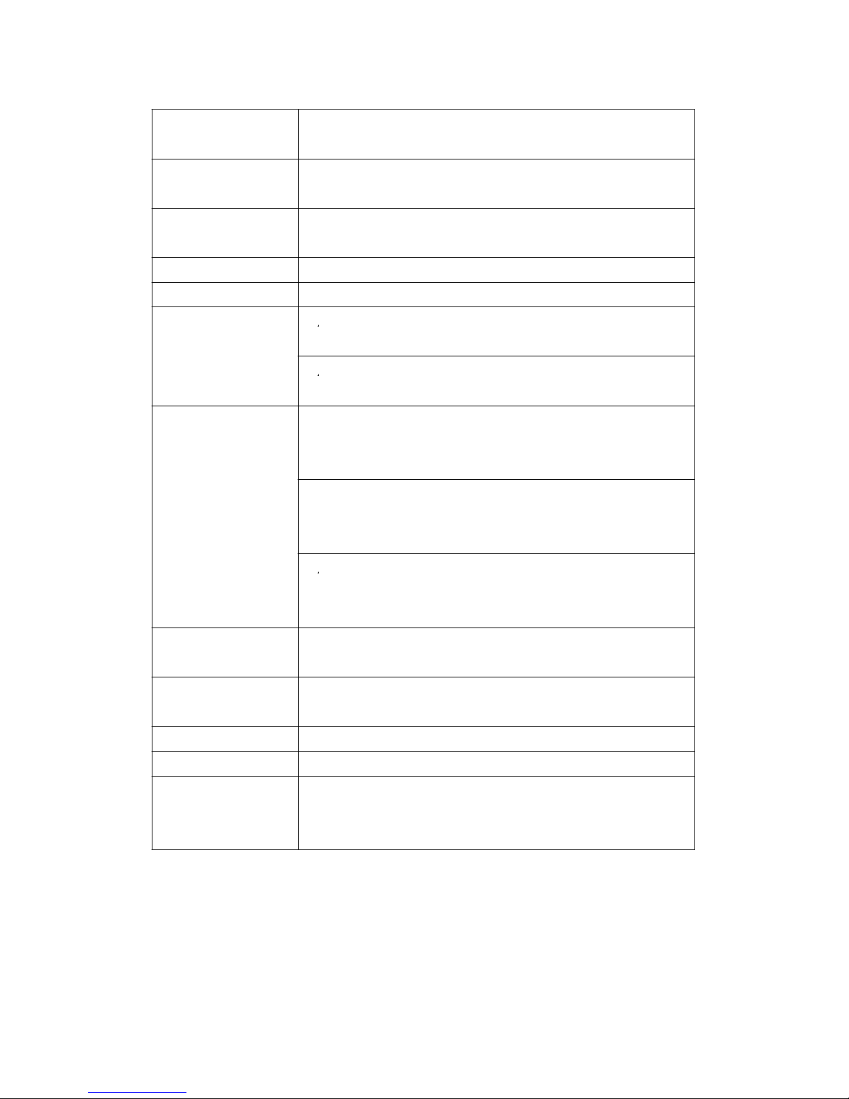
Overload Max. 150 kg.
Capacity
Full Scale Less than 1 mm.
Deflection
Zero/tare Max. full capacity.
Control
Sensor type S type load cell.
Circuit Exclusive microprocessor LSI-circuit.
Power Supply
*
A
Alkaline or heavy duty DC 1.5 V battery
( UM3, AA ) x 6 PCs, or equivalent.
*
A
DC 9V adapter input. ( AC/DC power
adapter is optional ).
Power Current Normal operation ( w/o SD card save
data and LCD Backlight is OFF) :
Approx. DC 7 mA.
When SD card save the data and LCD
Backlight is OFF) :
Approx. DC 38 mA.
* AIf LCD backlight on, the power
consumption will increase approx.
3 mA.
Operating 0 to 50 ( 32 to 122 ).℃℃℉ ℉
Temperature
Operating Less than 80% RH.
Humidity
Dimension 215 x 90 x 45 mm ( 8.5 x 3.5 x 1.8 inch ).
Weight 650 g ( 1.43 LB )/with batteries.
Mounting Main instrument with mounting holes are
Holes provided on the back case, easy stand
mounting.
4
Page 8

Accessories Operating manual ........................1 PC.
Included 100 Kg sensor with 2 hooks and
2 meter cable...............................1 PC.
Carrying case ..............................1 PC.
Optional *
T
SD memory card ( 2 GB )
Accessories * Test stand, Model : FS-1001
* Electrical test stand, Model : FS-1002
* Wedge grip, Model : WG-01
* RS232 cable, Model : UPCB-02.
* USB cable, Model : USB-01
* Software for data logging & data
recorder.
Model : SW-U801-WIN.
5
Page 9
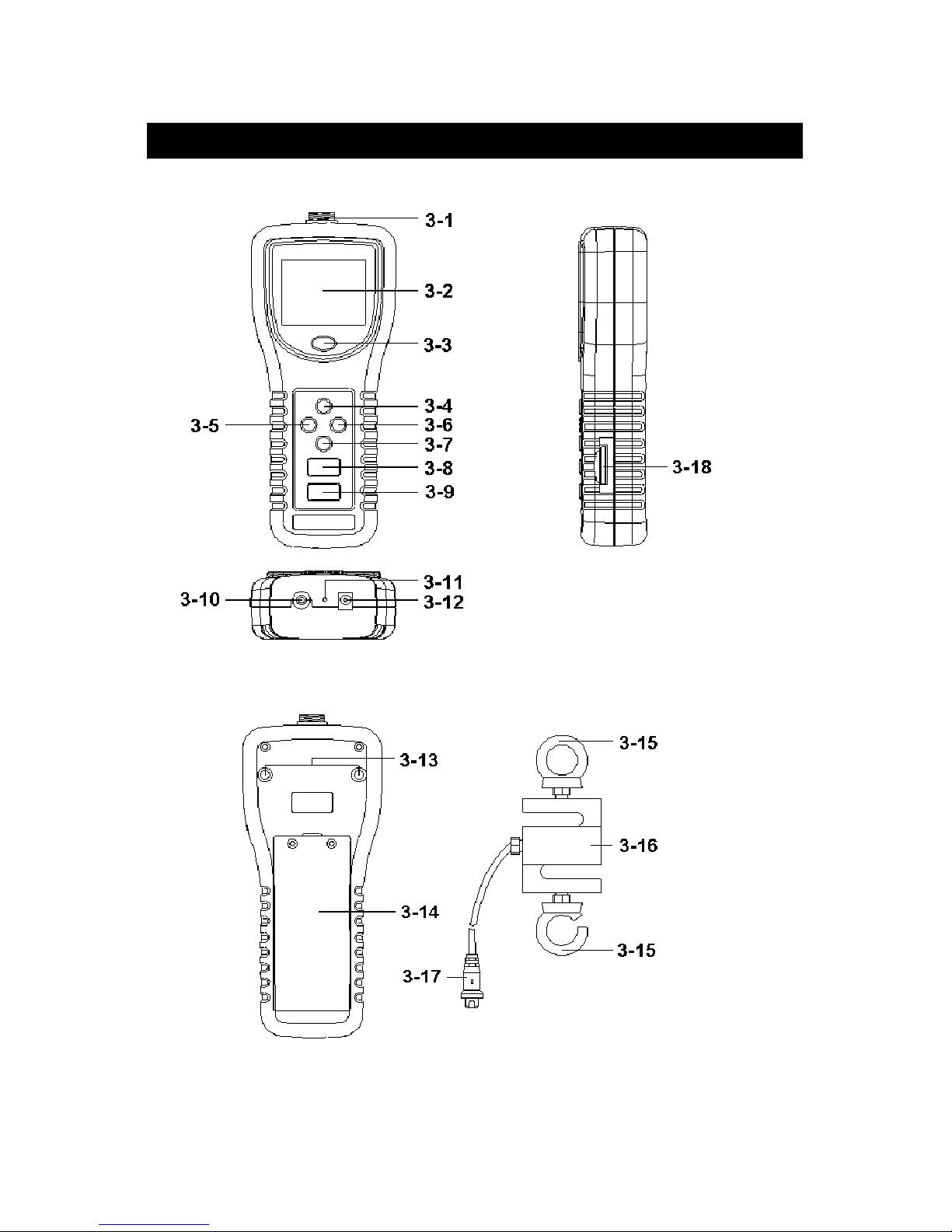
3. FRONT PANEL DESCRIPTIONS
Fig. 1
6
Page 10

3-1 Sensor Input socket
3-2 LCD Display
3-3 Power/BACKLIGHT Button
3-4 /ZERO Button▲
3-5 Fast/SLOW/ESC Button
3-6 PEAK/ENTER Button
3-7 DISPLAY REVERSE/ Button▼
3-8 TIME/SET Button
3-9 LOGGER/SAMPLING CHECK Button
3-10 RS-232 output terminal
3-11 Reset terminal
3-12 DC 9V Power Adapter Input Socket
3-13 Mounting Holes/fixing Screws
3-14 Battery Cover/Compartment
3-15 Sensor Hooks
3-16 Sensor ( force sensor )
3-17 Sensor plug
3-18 SD card socket
7
Page 11

4. MEASURING PROCEDURE
4-1 Pay attention for the measurement
1)Compression measurement, the display will show the
" - " mark automatically.
Tension Compression
2)During the measurement, the SENSING HEAD along
the adapter has to be on a line with measuring object.
( ref. Fig. 2 )
Fig. 2
8
Page 12

3)Rotate the SENSING HEAD is prohibited. Some certain
angles between SENSING HEAD & measuring object
are not allowed.
4-2 Normal Measurement
1)
Power on/off
Power on :
Press " Power Button " ( 3-3, Fig. 1) once.
Power off :
During power on, press " Power Button " ( 3-3 , Fig. 1 )
> 2 seconds. will power off.
2)Determine display unit of Kg, lb or Newton by selecting
the unit at first with default, refer to chapter 7
" ADVANCED SETTING ".
3)* Insert the " Sensor Plug " ( 3-17, Fig. 1 ) to
" Sensor Input socket " ( 3-1, Fig. 1)
* Connect " Sensor " ( 3-16, Fig. 1 ) with the " Measuring
Object " via the " Sensor hook " ( 3-15, Fig. 1 ) in
straight line.
4)" Zero Adjust " by pushing " Zero Button "
( 3-4, Fig. 1 ) before every measurement.
9
Page 13

5)Start measurement by giving force (push or pull), then the
LCD will display the Average reading value.
Note :
*
During the measurement, if intend to change
the display direction, just push the " Reverse
Button " ( 3-7, Fig. 1 ) once.
*There are two kind sampling time of display, FAST
and SLOW. Push the " FAST/SLOW Button " once in
sequence ( 3-5, Fig. 1 ), if the upper left corner of
LCD show " FAST " indicator , then the display
reading is under the operation of fast sampling time
measurement. If the LCD show " SLOW " indicator,
the display reading is under the slow sampling time
measurement.
*
Over range display of tension function, LCD
will show " "
*Over range display of compression function, LCD
will show " "
4-3 Peak Hold Measurement
The meter can measure the peak value of force both of
tension & compression operation. The operation
procedures of Peak Hold Measurement are same as above
" 4-2 Normal Measurement " but should press the
" PEAK Button " ( 3-6, Fig. 1 ) once, the Display will
show the " PEAK " indicator, then during the measurement
the Display will freeze on the Peak hold value.
10
Page 14

4-4 LCD Back Light On/Off
During the measurement, press the " BACKLIGHT Button "
( 3-3, Fig. 1 ) once the LCD Back Light will be ON. During
the LCD Back Light ON, press the " BACKLIGHT Button "
once again, the LCD Back Light will be OFF again.
4-5 Alarm beeper
If the measuring value over the 100.00 Kg, the internal
buzzer will sound for warning.
5. DATALOGGER
5-1 Preparation before execute datalogger function
a. Insert the SD card
* It recommend use memory card 4 GB.≦
Prepare a " SD memory card " ( 1 GB to 16 GB, optional ),
insert the SD card into the " SD card socket " ( 3-18, Fig. 1 ).
* When plug in the SD card, the up side of the SD card
should face against the down case.
b. SD card Format
If SD card just the first time use into the meter, it
recommend to make the " SD card Format " at first. ,
please refer chapter 7-1, page 20.
*It recommend strongly, do not use memory cards that
have been formatted by other meter or by a computer.
Reformat the memory card with your meter.
c. Time setting
If the meter is used at first time, it should to adjust the
clock time exactly, please refer chapter 7-2, page 20.
11
Page 15

d. Decimal format setting
The numerical data structure of SD card is
default used the " . " as the decimal, for
example "20.6" "1000.53" . But in certain
countries ( Europe ...) is used the " , " as the
decimal point, for example " 20, 6 "
"1000,53". Under such situation, it should
change the Decimal character at first, details
of setting the Decimal point, refer to Chapter
7-8, page 24.
5-2 Normal record mode
Auto Datalogger ( Set sampling time 1 second )≧
a. Start the datalogger
Press the " LOGGER Button ( 3-9, Fig. 1 ) > 2 seconds
continuously , the LCD will show the indicator " DATA
RECORD " with flashing, at the same time the measuring
data along the time information will be saved into the
memory circuit.
Remark :
*
How to set the sampling time, refer to Chapter 7-3
page 21.
*
How to set the beeper sound is enable, refer to
Chapter 7-6, page 23.
12
Page 16

b. Pause the datalogger
During execute the Datalogger function , if press the
" Logger Button " ( 3-9, Fig. 1 ) once will pause the
Datalogger function ( stop to save the measuring data
into the memory circuit temporally ). In the same time
the indicator of " DATA RECORD " will stop to flash..
Remark :
If press the " Logger Button " ( 3-9, Fig. 1 ) once again
will execute the Datalogger again, the bottom text of
DATA RECORD " will flashing .
c. Finish the Datalogger
During pause the Datalogger ( or pause the Datalogger ),
Press the " LOGGER Button ( 3-9, Fig. 1 ) > 2 seconds
continuously, the " DATA RECORD " indicator will be
disappeared and finish the Datalogger.
5-3 Normal record mode
Manual Datalogger ( Set sampling time = 0 second )
a. Set sampling time is to 0 second
Press the " LOGGER Button ( 3-9, Fig. 1 ) > 2 seconds
continuously, the LCD will show the indicator " DATA
RECORD " ( not flashing ). Press the " Logger Button "
( 3-9, Fig. 1 ) once, the " DATA RECORD " indicator will
flash once a while and Beeper will sound once, at the
same time the measuring data along the time information
will be saved into the memory circuit. The lower Display
will show the Position ( Location ) no. and saved into the
SD card too.
13
Page 17

Remark :
During execute the Manual Datalogger, press the " ▲
Button " ( 3-4, Fig, 1 ) or " Button " ( 3-7, Fig. 1 ) to▼
set the measuring Location no. ( 1 to 99, for example
room 1 to room 99 ) to identify the measurement location
, the lower Display will show P x ( x = 1 to 99 ).
b. Finish the Datalogger
Press the " LOGGER Button ( 3-9, Fig. 1 ) > 2 seconds
continuously, the " DATA RECORD " indicator will be
disappeared and finish the Datalogger.
5-4 Peak hold record mode
( Fast Datalogger )
1)Recommend the Force gauge install to the Test stand
( such as FS-1001, FS-1002.. ), Power on the meter.
2)Press the " PEAK Button " ( 3-6, Fig. 1 ) once, the Display
will the indicator " PEAK " and " FAST ".
3)Press the " Zero Button " ( 3-4, Fig. 1 ) once, the Display
will set to " ZERO " value.
4)* Press the " LOGGER Button ( 3-9, Fig. 1 ) once , the
LCD will show the indicator " DATA RECORD " at the
same time the sampling time value in ms ( milli
seconds ) will appear a while in the bottom LCD, for
example " 10 ". Now the meter is ready for the " Peak
hold record mode ( Fast Datalogger measurement ) ".
* If apply the force value ( tension/compression ) > 1.00
Kg ( 1% full capacity ), then the measurement value
according the sampling period will save to the internal
memory circuit in sequence.
Remark :
*
How to set the sampling time, refer to Chapter 7-4
page 22.
14
Page 18

* When the peak value is got, the LCD indicator "
DATA RECORD " will be disappeared . The indicator
will show " PEAK " indicator only, in the same time
the peak value will freeze on the Display
* Following the bottom LCD will show the data record
no. and count down to zero, in the same time all the
memory data will save into the SD memory card.
5-5 Check the time information
During the normal measurement screen ( not execute
the Datalogger ),
1)If press " Time Button " ( 3-8, Fig. 1 ) once , the lower
LCD display will present the time information of
Hour/Minute/Second ( h.m.s ) in the lower Display.
2)If press " Time Button " ( 3-8, Fig. 1 ) once again , the
lower LCD display will present the time information of
Year/Month/Date ( yy.mm.dd ) in the lower Display.
3)If press " Time Button " ( 3-8, Fig. 1 ) once again ,
the LCD will return to normal screen.
5-6 Check sampling time information
During the normal measurement screen ( not execute the
Datalogger ), If press " Sampling Button " ( 3-9, Fig. 1 )
once , the lower LCD display will present the Sampling
time information in second unit.
5-7 SD Card Data structure
1)When the first time, the SD card is used into the meter,
the SD card will generate a route :
FGC01
15
Page 19

2)If the first time to execute the Datalogger,
under the route FGC01\, will generate a new
file name FGC01001.XLS.
After exist the Datalogger, then execute again,
the data will save to the FGC01001.XLS until
Data column reach to 30,000 columns, then
will generate a new file, for example FGC01002.XLS
3)Under the folder FGC01\, if the total files more
than 99 files, will generate anew route, such as
FGC02\ ........
4)The file's route structure :
FGC01\
FGC01001.XLS
FGC01002.XLS
.....................
FGC01099.XLS
FGC02\
FGC02001.XLS
FGC02002.XLS
.....................
FGC02099.XLS
FGCXX\
.....................
.....................
Remark :
XX : Max. value is 10.
16
Page 20

6. Saving data from the SD card
to the computer ( EXCEL software )
1)After execute the Data Logger function, take away the
SD card out from the " SD card socket " ( 3-20, Fig. 1 ).
2)Plug in the SD card into the Computer's SD card slot
( if your computer build in this installation ) or
insert the SD card into the " SD card adapter ". then
connect the " SD card adapter " into the computer.
3)Power ON the computer and run the " EXCEL software ".
Down load the saving data file ( for example the file
name : FGC01001.XLS, FGC01002.XLS ) from the SD
card to the computer. The saving data will present into
the EXCEL software screen ( for example as following
EXCEL data screens ) , then user can use those EXCEL
data to make the further Data or Graphic analysis
usefully.
EXCEL data screen
(
for example, normal record mode
)
17
Page 21

EXCEL data screen ( for example, peak hold record mode )
EXCEL graphic screen ( for example, graphic 1 )
18
Page 22

EXCEL graphic screen ( for example, graphic 2
)
7. ADVANCED SETTING
Under do not execute the Datalogger function,
press the " SET Button " ( 3-8, Fig. 1 ) continuously at
least two seconds will enter the " Advanced Setting " mode.
then press the " SET Button " ( 3-8, Fig. 1 ) once a while
in sequence to select the eight main function, the
display will show :
Sd F..... SD memory card Format
dAtE.....
.
Set clock time ( Year/Month/Date, Hour/Minute/
Second )
SP-t......Set sampling time for normal record mode
HSPt.....Set sampling time for peak record mode
PoFF.....Auto power OFF management
bEEP....
.
Set beeper sound ON/OFF
unit......
.
Set the measurement unit
dEC......
.
Set SD card Decimal character
ESC...... Escape from the advanced setting
19
Page 23

Remark :
During execute the " Advanced Setting " function,
if press " ESC Button " ( 3-5, Fig. 1 ) will exit the
" Advanced Setting " function, the LCD will return
to normal screen.
7-1 SD memory card Format
When the lower display show " Sd F "
1)Use the " Button " ( 3-4, Fig. 1 ) or " Button " (▲▼
3-7, Fig. 1 ) to select the upper value to " yES " or
" no ".
yES - Intend to format the SD memory card
no - Not execute the SD memory card format
2)If select the upper to " yES ", press the " Enter Button
" ( 3-6, Fig. 1 ) once again, the Display will show text
" yES Enter " to confirm again, if make sure to do the
SD memory card format, then press " Enter Button "
once will format the SD memory clear all the existing
data that already saving into the SD card.
7-2 Set clock time ( Year/Month/Date,
Hour/Minute/ Second )
When the upper display show " dAtE "
1)Use the " Button " ( 3-4, Fig. 1 ) or " Button " ▲▼
( 3-7, Fig. 1 ) to adjust the value ( Setting start from
Year value ). After the desired value is set, press the
" Enter Button " ( 3-6, Fig. 1 ) once will going to
next value adjustment ( for example, first setting
value is Year then next to adjust Month, Date, Hour,
Minute, Second value ).
Remark : The adjusted value will be flashed.
20
Page 24

2)After set all the time value ( Year, Month, Date, Hour,
Minute, Second ), press the " SET Button " ( 3-8, Fig.
1 ) once will save the time value, then the screen will
jump to Sampling time " setting screen ( Chapter 7-3 ).
Remark :
After the time value is setting, the internal clock will
run precisely even Power off if the battery is under
normal condition ( No low battery power ).
7-3 Set sampling time ( normal record mode )
When the upper display show " SP-t "
1)Use the " Button " ( 3-4, Fig. 1 ) or " Button " ▲▼
( 3-7, Fig. 1 ) to adjust the value ( Setting start from
Hour value ). After the desired value is set, press the
" Enter Button " ( 3-6, Fig. 1 ) once will going to next
value adjustment ( for example, first setting value is
Hour then next to adjust Minute, Second value ).
Remark :
The adjusted value will be flashed.
2)After set all the sampling time value ( Hour, Minute,
Second ), press the " SET Button " ( 3-8, Fig. 1 ) once
will save the sampling value with default then the
screen will jump to " Set sampling time for peak
record mode " setting screen ( Chapter 7-4 ).
21
Page 25

7-4 Set sampling time for peak record mode
When the lower display show " HSPt "
1)Use the " Button " ( 3-4, Fig. 1 ) or " Button " ▲▼
( 3-7, Fig. 1 ) to adjust the value ( adjust unit is milli
seconds, each step is 10 ms, setting start from 10 ms ).
After the desired value is set, press the " Enter Button "
( 3-6, Fig. 1 ) will save the setting value with default.
Remark :
The adjusted value range is from 10 ms to 500 ms,
2)After set the sampling time value, press the " SET
Button " ( 3-6, Fig. 1 ) once the screen will jump to "
Auto power OFF " setting screen ( Chapter 7-5 ).
7-5 Auto power OFF management
When the lower display show " PoFF "
1)Use the " Button " ( 3-4, Fig. 1 ) or " Button " ▲▼
( 3-7, Fig. 1 ) to select the upper value to " yES " or
" no ".
yES - Auto Power Off management will enable.
no - Auto Power Off management will disable.
2)After select the upper text to " yES " or " no ", press the
" Enter Button " ( 3-6, Fig. 1 ) will save the setting
function with default.
22
Page 26

7-6 Set beeper sound ON/OFF
When the lower display show " bEEP "
1)Use the " Button " ( 3-4, Fig. 1 ) or " Button " ▲▼
( 3-7, Fig. 1 ) to select the upper value to " yES " or
" no ".
yES - Meter's beep sound will be ON with default.
no - Meter's beep sound will be OFF with default.
2)After select the upper text to " yES " or " no ", press the
" Enter Button " ( 3-6, Fig. 1 ) will save the setting
function with default.
7-7 Set the measurement unit
When the lower display show " unit "
1)Use the " Button " ( 3-4, Fig. 1 ) or " Button " ▲▼
( 3-7, Fig. 1 ) to select the measurement unit in
" Kg ", " lb ", " N ", in the same time the upper LCD
will show the full scale value for the corresponding
measurement unit.
Remark :
Kg - Killo gram, full scale is 100.00 Kg
lb - Pound, full scale is 220.50 lb
N - Newton , full scale is 980.6 N
2)After select the measurement unit, press the " Enter
Button " ( 3-6, Fig. 1 ) will save the setting function
with default.
23
Page 27

7-8 Decimal point of SD card setting
The numerical data structure of SD card is default used
the " . " as the decimal, for example "20.6" "1000.53" .
But in certain countries ( Europe ...) is used the " , " as
the decimal point, for example " 20,6 " "1000,53".
Under such situation, it should change the Decimal
character at first.
When the lower display show " dEC "
1)Use the " Button " ( 3-4, Fig. 1 ) or " Button " ▲▼
( 3-7, Fig. 1 ) to select the upper text to " bASIC " or
" Euro ".
USA - Use " . " as the Decimal point with default.
Euro - Use " , " as the Decimal point with default.
2)After select the upper text to " USA " or " Euro ",
press the " Enter Button " ( 3-6, Fig. 1 ) will save the
setting function with default.
7-9 ESC
When the display show " ESC "
When the Display show the text " ESC ", then press the
" SET Button " ( 3-8, Fig. 1 ) or " ESC Button " ( 3-5, Fig. 1 )
will finish the Advanced Setting procedures.
Remark :
During execute the " Advanced Setting " function,
if press " ESC Button " ( 3-5, Fig. 1 ) will exit the
" Advanced Setting " function, the LCD will return
to normal screen.
24
Page 28

8. POWER SUPPLY from DC
ADAPTER
The meter also can supply the power supply from the
DC 9V Power Adapter ( optional ). Insert the plug of
Power Adapter into " DC 9V Power Adapter Input Socket
" ( 3-12, Fig. 1 ). The meter will permanent power ON
when use the DC ADAPTER power supply ( The power
Button function is disable ).
9. BATTERY REPLACEMENT
1)When the left corner of LCD display show " ", it
is necessary to replace the battery. However, in-spec.
measurement may still be made for several hours after
low battery indicator appears before the instrument
become inaccurate.
2)Loose the screws of the " Battery Cover " ( 3-14, Fig. 1 )
and take away the " Battery Cover " from the instrument
and remove the battery.
3)Replace with DC 1.5 V battery ( UM3, AA,
Alkaline/heavy duty ) x 6 PCs, and reinstate the cover.
4)Make sure the battery cover is secured after changing batteries.
10. SYSTEM RESET
If the meter happen the troubles such as :
CPU system is hold ( for example, the key button can
not be operated... ).
Then make the system RESET will fix the problem.
The system RESET procedures will be either following
method :
During the power on, use a pin to press the " Reset Button "
( 3-11, Fig. 1 ) once a while will reset the circuit system.
25
Page 29

11. RS232 PC SERIAL INTERFACE
The instrument has RS232 PC serial interface via a 3.5 mm
terminal ( 3-10, Fig. 1 ).
The data output is a 16 digit stream which can be
utilized for user's specific application.
A RS232 lead with the following connection will be
required to link the instrument with the PC serial port.
Meter PC
(9W 'D" Connector)
Center Pin..........................Pin 4
(3.5 mm jack plug)
Ground/shield......................
.
Pin 2
2.2 K
resister
Pin 5
The 16 digits data stream will be displayed in the
following format :
D15 D14 D13 D12 D11 D10 D9 D8 D7 D6 D5 D4 D3 D2 D1 D0
Each digit indicate the following status :
D15 Start Word
D14 4
D13 1
D12 and Anunuciator for Display
D11 g = 57 Newton = 59 oz =58
Kg = 55 LB = 56
26
Page 30

D10 Polarity
0 = Positive 1 = Negative
D9 Decimal Point(DP), position from right to the
left
0 = No DP, 1= 1 DP, 2 = 2 DP, 3 = 3 DP
D8 to D1 Display reading, D1 = LSD, D8 = MSD
For example :
If the display reading is 1234, then D8 to D1 is : 1234
D0 End Word
RS232 FORMAT : 9600, N, 8, 1
Baud rate 9600
Parity No parity
Data bit no. 8 Data bits
Stop bit 1 Stop bit
12. MOUNTING HOLES & OPTIONAL
TEST STAND
FORCE GAUGE is a precise instrument, best results are
obtained when the gauge is fitted to a test stand.
Mounting holes ( 3-13, Fig. 1 ) are provided on the back
of the gauge for easy stand mounting.
Optional Test Stand & accessory :
a.100 Kg capacity
TEST STAND, Model : FS-1001
Test stand, cooperate with Force gauge, whole system
will be become the useful tool for material's tension &
compression analysis.
Size : 630 x 250 x 230 mm. Weight : 7.02 Kg ( 15.4 LB ).
Max. capacity : 100 Kg ( 220 lb ).
27
Page 31

b.150 Kg capacity
ELECTRICAL TEST STAND for Force gauge
Model : FS-1002-110V, FS-1002-220V
* Max. capacity : 150 Kg ( 330 lb.. ).
* Max. tension distance : 450 mm.
* Net weight : 17.6 Kg.
* Size ( WDH ) :
220 mm x 280 mm x 800 mm.
* Buttons :
Up button, Down button, Stop button.
* FS-1002-110V :
Power supply AC 110V, 50/60 Hz.
* FS-1002-220V :
Power supply AC 220V/230V, 50/60 Hz.
13. APPLICATIONS
13-1 Electronics
* Test strength of solder points and spot welds on circuit
boards.
* Test wire wraps on clip connection.
* Test pull strength of modified wire wrap connection on
posts.
* Test spring clip insertion and withdrawal forces.
* Pull test welds in micro-electronic devices.
* Measure torque, timing belt tension, sliding friction, etc.,
on computer peripheral equipment.
* Test P.C. board insertion force.
* Test insertion and withdrawal forces of various circuit
components such as transistors and integrated circuits.
* Test actuating force of snap action switches.
28
Page 32

13-2 Business Equipment
* Measure force required to perforate cards.
* Measure load on slitter knives.
* Measure actuating requirements of typewriter.
* Test clutch release force.
* Measure torque, timing belt tension (by deflection),
sliding friction, etc., on computer peripheral equipment.
* Test adhesion strength of labels and stickers.
* Test load on paper thickness gages.
* Measure tension of pencils.
* Test actuating requirements on push buttons and flip
switches.
13-3 Chemical & Plastics
* Test film bond strengths.
* Tensile test rubber, fibers and filaments.
* Measure firmness of polyurethane foam.
* Test crush strength of pills (medicine)
* Test peel strength of adhesives.
* measure compression of ceramic compounds.
* Test vacuum take-down pressure on process machines.
13-4 Machinery & Manufacturing
* Test load on wire feel
* Test force to open cabinet doors.
* Test sprocket chain tension.
* Test pull-out forced of drive shaft.
* Rate testing of springs in systems.
* Calibrate a cantilever beam-type Apparatus to obtain a
force/deflection relationship.
29
Page 33

13-5 Automotive
* Measure force of seat belt retractors.
* Measure arm pressure of windshield wipers.
* Measure flip force in mechanical snap action switches.
* Test effort to operate hand tool.
* Test forces required to move linkages and tension cables.
* Measure force of odometer pull.
* Test peel strength of vinyl insert bonded to body side
moldings
* Evaluate physical efforts (door, look, hood, glove
compartment, brake pedal, etc.).
13-6 Other Industries
* Measure pedal depression force in aircraft.
* Test hardness of gypsum wallboard.
* Test keyboard and pedal contact force of organs and
pianos.
* Test force to remove cover tops of aerosol cans.
* Measure trigger pulling forces on firearms, hand tools etc.
* Test firmness of sausages in casings.
* Test integrity of seals on blister packages and plastic bags.
* Test pressure of surgical instruments (forceps, scissors).
* Test fruit removal force and fruit firmness.
* Measure force on spindles of photographic equipment
30
1101-FG6100SD
 Loading...