

Page 1

System Programming User Guide
For Hub Firmware Version: 1.14
INSTALL
P/N 041571j
MAINTAIN
Page 2

P/N 041571j
Table of Contents
What is a Vive system? .....................................................................................................................................................4
Components ........................................................................................................................................................................4
Installation / Wiring ...............................................................................................................................................................4
Lutron Vive App ....................................................................................................................................................................5
Initial Configuration ...........................................................................................................................................................6
Connect to the Hub (via browser) ....................................................................................................................................... 6
Set Up Wi-Fi Connection (via browser) .............................................................................................................................. 6
Create a Password for the Hub .....................................................................................................................................8
Commissioning ....................................................................................................................................................................9
Create an Area .....................................................................................................................................................................9
Add Devices .......................................................................................................................................................................10
Add a Pico Remote Control and Assign Devices ................................................................................................................ 10
Add a Sensor and Assign Devices .................................................................................................................................... 14
Add Devices Directly to the Hub ....................................................................................................................................... 16
Find Devices not Showing up in Discovery ............................................................................................................ 18
Device Too Far Away ......................................................................................................................................................... 18
Unsupported Device .........................................................................................................................................................18
Devices Set Up Without the Hub ......................................................................................................................................18
Rename Devices ................................................................................................................................................................19
Troubleshoot Devices ...................................................................................................................................................... 19
Programming ......................................................................................................................................................................20
Occupancy / Vacancy Sensor Settings .............................................................................................................................20
Status ............................................................................................................................................................................20
Sensitivity ..................................................................................................................................................................20
Timeout .....................................................................................................................................................................20
Occupanc y Settings / Prog ramming ..................................................................................................................................20
Occupa ncy / Vacancy Be havior ........................................................................................................................................20
Occupied / Unoccupied Levels .........................................................................................................................................21
All Occupancy Sensors Work Together .............................................................................................................................22
Occupancy Grouping ...................................................................................................................................................................... 23
Control Receptacles / CCO Modules Using Occupancy Grouping ................................................................................................ 23
Occupancy Dependency ................................................................................................................................................................. 25
Tuni ng ..................................................................................................................................................................................... 26
High-en d / Low-end Trim ...................................................................................................................................................26
Minimum Light Level ........................................................................................................................................................27
Maximum Light Level ......................................................................................................................................................28
Daylighting ...........................................................................................................................................................................29
Best Practices....................................................................................................................................................................29
Individual Fixture Sensors ................................................................................................................................................29
Radio Powr Savr Daylight Sensors ................................................................................................................................... 30
Multi-row Daylighting ......................................................................................................................................................30
Schedules .............................................................................................................................................................................32
Create Schedule ................................................................................................................................................................32
Modify and Test Schedules ..............................................................................................................................................36
Continued on next page...
2
Page 3

P/N 041571j
Table of Contents (continued)
Alerts ......................................................................................................................................................................................37
Load Shed ............................................................................................................................................................................38
OpenADR ..............................................................................................................................................................................40
Emergency ...........................................................................................................................................................................43
Cloud Backup .....................................................................................................................................................................43
BACnet ...................................................................................................................................................................................44
Settings ..............................................................................................................................................................................44
API Integrations .................................................................................................................................................................47
Instructions to Integrate ....................................................................................................................................................47
Scenes ...................................................................................................................................................................................49
Create a Scene ..................................................................................................................................................................49
Control and Monitor .........................................................................................................................................................52
Runtime Status ..................................................................................................................................................................55
Fixture Sensor Gets Connected .......................................................................................................................................55
Configure the Hub ............................................................................................................................................................57
Firmware Update ...............................................................................................................................................................57
Ethernet Settings ...............................................................................................................................................................58
Wi-Fi Settings ....................................................................................................................................................................59
Time & Date / Location .......................................................................................................................................................60
Accessing Other Hubs on the Wired Network .................................................................................................................60
Hub Support File ................................................................................................................................................................61
Reset Passwords and Settings .........................................................................................................................................62
Security Log ........................................................................................................................................................................63
Security Certificates ........................................................................................................................................................64
Vive Vue .................................................................................................................................................................................65
Lutron Contact Numbers ...............................................................................................................................................66
3
Page 4

What is a Vive system?
The Lutron Vive system is a simple and scalable wireless lighting control solution for new and existing commercial buildings.
Some of the many benefits of a Vive system are:
• Flexibility needed to design a building
• Wireless technology simplifies installation and reduces callbacks
• Maximize productivity and building performance
• Dependability and confidence that the system will work from the start and will keep working
• Visible and traceable energy savings control and monitoring
Components
Vive wireless hubLutron Vive app Fixture mountCeiling mount
Emergency
PowPak controller
P/N 041571j
Radio Powr Savr
occupancy / vacancy sensor
Radio Powr Savr
daylight sensor
Pico remote
control
Wallbox mount
Maestro Wireless
dimme r / switch
Integral fixture control
PowPak controller
with J-box
Maestro Wireless dimmer/
switch with sensor
PowPak wireless
fixture controller with
fixture sensor
Wireless receptacle
PowPak
fixture sensor
Dimming module
Installation / Wiring
For directions on how to install Vive devices, refer to the installation instructions included with the product. This guide is based on
the premise that all devices are already properly installed and wired.
4
Page 5

Lutron Vive App
The Lutron Vive app is available for download on iOSR and AndroidT
devices. The app is compatible with Vive hub software version 1.5
and newer. Older versions of hub software must be upgraded before
using the Vive app.
1. Download the app from the App Store or the Google PlayT store.
2. Launch the app and follow the instructions to create a myLutron
account. If you already have a myLutron account, enter the account
credentials into the app.
3. Verify your email address and login to your account.
4. Create a project in the app and add Vive hubs to the project. The
app provides a consolidated view of all projects and every hub
within a project. The app allows an installer to activate the extended
warranty and “hand off” a project to the customer.
Install
P/N 041571j
When a project is handed off to the customer, an e-mail that
contains the project details will be sent to the customer. The
customer will be able to access the project, view the hubs, and see
other details related to the project.
5
Page 6

Initial Configuration
The Vive software is used to program the Vive wireless hub (known
as “hub” hereafter). A hub can be accessed via Lutron Vive app
or a web browser (Google ChromeT browser or Safari application
program recommended).
If the Vive app is used, follow the instructions in the app to create a
project and add hubs to it. Multiple users can be invited to a project
and can access and collaborate on a project from different devices.
Note: The hub can be programmed by connecting a smart device
(e.g., phone, tablet, or laptop) to the built-in Wi-FiR chip of the hub.
There is no requirement to connect to external or building Wi-Fi
networks.
Connect to the Hub (via browser)
1. Enable the Wi-Fi connection on the smart device.
Install
P/N 041571j
2. Navigate to the list of available networks. When in range of the hub,
you should see a network name similar to “Vive-017d20b9”. The text
that follows “Vive” in the network name is the serial number of the
hub. Connect to this network.
Set Up Wi-Fi Connection (via browser)
1. Open a web browser and type “vive.lutron.com” into the address
bar. An image of the hub will appear and the antenna on the hub
that you are connected to will flash white. If this is not the correct
hub, return to the list of Wi-Fi networks and choose a different
network. Once you have found the correct hub, tap “Yes, setup this
hub”.
Note: If you want to set up the hub via the app, follow instructions in
the app to set up a project and add hubs.
2. Tap the current name of the hub and rename it (e.g., Vive_floorOne).
This will be the Wi-Fi network name of this hub. A good descriptive
name will help you and others identify this hub later.
3. Tap “Next”.
Continued on next page...
6
Page 7

Initial Configuration (continued)
4. Type in a secure password for the Wi-Fi network and tap “Done”.
A strong password is required to keep the account secure.
A password must:
a. be at “Medium” strength or higher.
b. contain at least 8 characters.
c. NOT contain these characters:
Follow the guidelines below to create a secure password.
• Increase the length of the password.
• Include both uppercase and lowercase letters.
• Add numbers or special characters.
Note: Tap “Show” or “Hide” to view or hide the password you are
typing.
‘x’ “x”
Install
P/N 041571j
5. Record the password in a secure location.
6. The hub will apply these settings and will disconnect from the
smart device. Go back to the Wi-Fi settings screen on the smart
device and connect to the hub network using the Wi-Fi name and
password you just created.
7. Return to the web browser and tap “Vive”. You will be presented with
a short tutorial on the Vive software. After reviewing the screens, tap
“Get Started”.
8. You will be directed to the main dashboard of the Vive software.
You can start creating the system by following the steps in the
Commissioning section of this guide.
7
Page 8

Create a Password for the Hub
Optional: Lutron recommends creating an additional password
for the hub. This increases security and is required to access the
application over a wired network.
1. From the main dashboard in the Vive software, tap “ ” and then
tap “Set Hub Sign In Password”.
Install
P/N 041571j
2. Enter a secure password for the hub and tap “Save”.
A strong password is required to keep the account secure.
A password must:
a. be at “Medium” strength or higher.
b. contain at least 8 characters.
c. NOT contain these characters:
Follow the guidelines below to create a secure password.
• Increase the length of the password.
• Include both uppercase and lowercase letters.
• Add numbers or special characters.
Note: Tap “Show” or “Hide” to view or hide the password you are
typing.
3. Record the password in a secure location.
‘x’ “x”
8
Page 9

Commissioning
The Vive system uses wireless signal strength measurements to
make adding fixtures to an area as quick and efficient as possible.
To take advantage of this technology, ensure that you are physically
in the room to be programed when performing these steps.
Create an Area
An area is a room or space in the building (e.g., conference room,
office, or hallway).
1. From the main dashboard in the Vive software,
tap “Rooms/Areas”.
Install
P/N 041571j
2. Select “Add a room or area” and name the area.
Continued on next page...
9
Page 10
Commissioning (continued)
Add Devices
Add a Pico Remote Control and Assign Devices
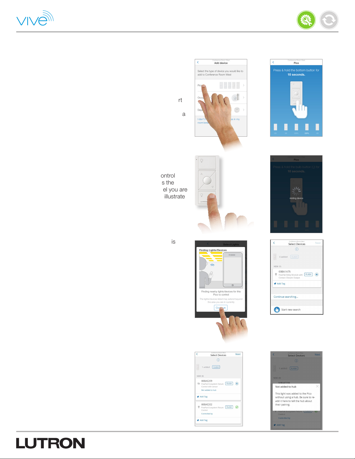
1. Select “Pico” as the type of device you want to add.
Note: You may choose to start with any device. You can even start
with a device that is not shown by selecting “I don’t have any of
these devices in my area”. The following steps are based on using a
Pico remote control.
2. Press and hold the bottom button on a Pico remote control for
10seconds until the screen says “Adding device”.
Note: You do not need to select the correct Pico remote control
model number before pressing the button. When you press the
button, the software will automatically recognize what model you are
using. The images in the software are a guide and may not illustrate
the exact model you are using.
Install
P/N 041571j
3. Tap “Continue” on the “Finding Lights / Devices” illustration. This
illustration will appear when adding the first device.
The software will find lights / devices nearby. You will be presented
with a list of devices that is ordered based on the strength of the
wireless signal. The devices closest to the Pico remote control will
appear at the top of the list. The serial number is the default name
for that device. The name can be changed later.
Note: Any lights / devices manually assigned (button press method)
to this Pico remote control will appear in the list as “Not added to
hub” and will need to be added. If the lights / devices are controlled
by any other controlling device (e.g., sensors), then they will need to
be reassigned to those devices via the hubvacancyva.
Note: The “Continue searching...” button can be used to reveal more
loads that may be farther away from the Pico remote control. Tap
this button if the devices do not appear in the list.
Note: In very large rooms (e.g., open office) you may need to move
around the space and tap “Start new search” several times to
capture all of the devices.
Continued on next page...
10
Page 11
Commissioning (continued)
Add Devices (continued)
Add a Pico Remote Control and Assign Devices
(continued)
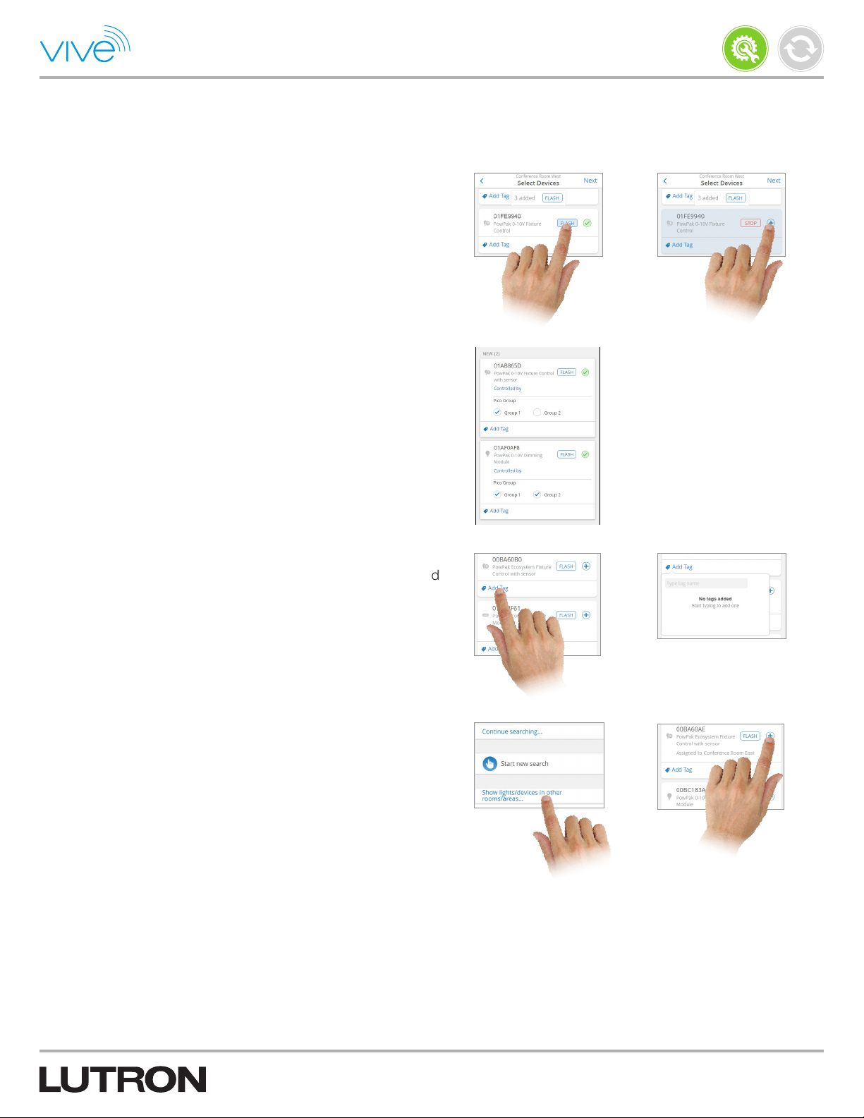
4. Tap “FLASH” and the load will flash to identify the device. If this is
the desired device, tap “+”. Repeat this step for each device that you
want to add to the area.
Note: PowPak receptacle controllers and CCO controllers will not
cycle on and off when you tap “FLASH”. Instead, these devices will
rapidly flash the LEDs on the front of the PowPak controller.
Note: If you are adding a 4-button 2-group Pico, you can add lights/
devices to one or both groups. These lights/devices will be then be
controlled by the Pico group button presses.
Install
P/N 041571j
5. Press “Add Tag” to tag a device, light, or control for future reference.
When adding controlling devices, these tags will be displayed and
the devices will not need to be flashed again for identification.
Tags are flexible and can be used in any way desired. They can be
used to name new areas. Examples of tags are “Sales Area”, “Front
Row”, and “Conference Room”.
6. A Pico remote control can control devices in multiple areas. To
add a device from another area, tap “Show lights / devices in other
rooms / areas...”. Select the desired area and tap “+”.
Note: The Pico wireless control must be located within 30ft (9m)
through walls or 60ft (18m) line-of-sight of all devices that it
is controlling.
Continued on next page...
11
Page 12
Commissioning (continued)
Add Devices (continued)
Add a Pico Remote Control and Assign Devices
(continued)
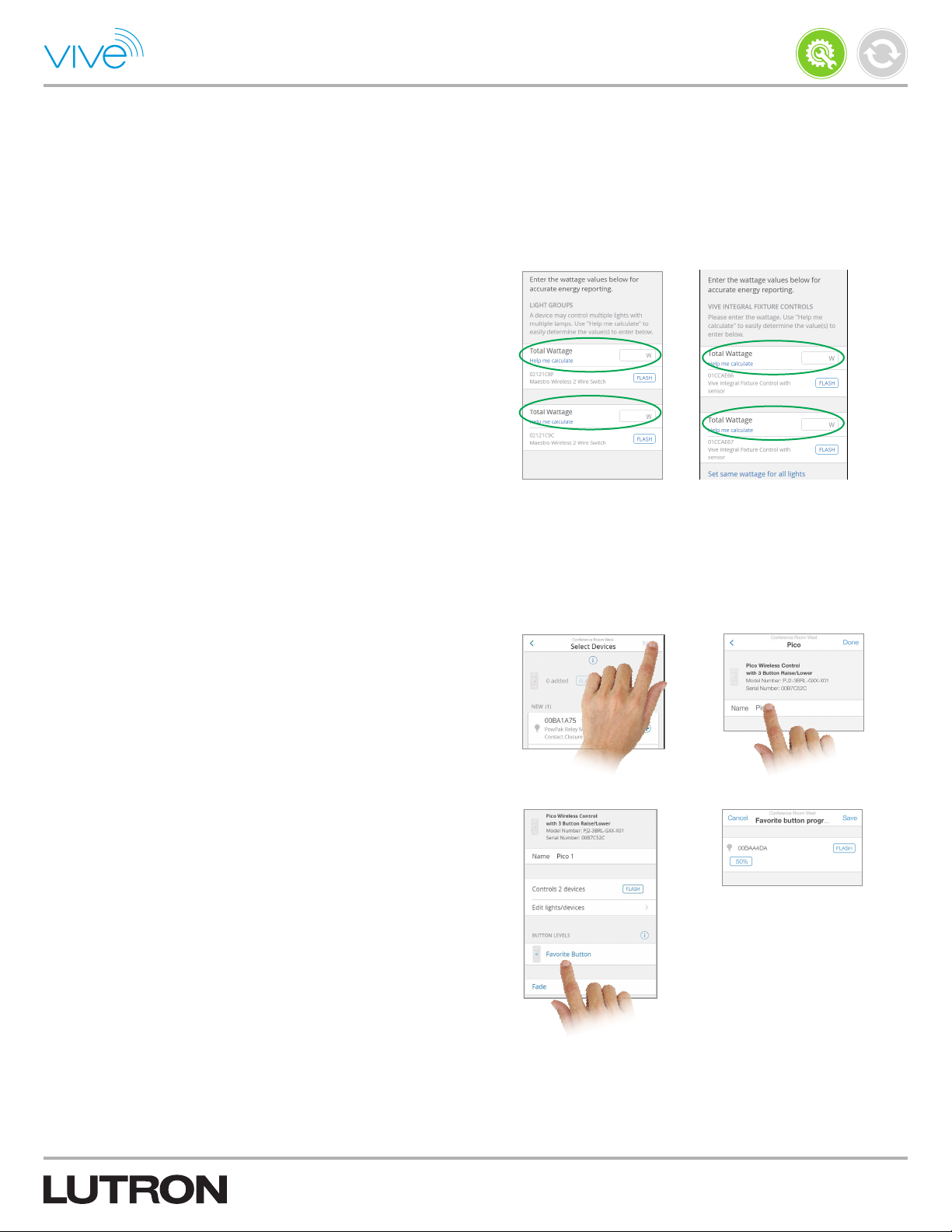
7. For each device added, enter the total wattage of the load(s) in the
appropriate “Wattage (W)” field. This is required to obtain the most
accurate energy reporting via the Vive software or BACnet.
Note: The Vive software will automatically report energy usage
for fixtures with a PowPak fixture controller. Vive Integral Fixture
Controls may also report energy usage automatically. Check the
Vive Integral Fixture Control product specification for more details.
Note: The wattage for PowPak receptacle controllers cannot be
entered since the wattage can change over time based on what is
plugged into the receptacle.
Note: The energy savings reported is instantaneous only. If
historical energy reporting is needed, a premium hub with BACnet
should be configured to work with a BMS. The BMS will store and
report historical energy savings data.
Install
P/N 041571j
Note: In the case that Vive Integral Fixture Controls were added, it
is possible to a enter common wattage for each device. It is also
possible to enter the wattage of each device individually by tapping
“Set different wattage for each light.”
8. Tap “Next” and rename the Pico remote control.
9. If using a 3BRL Pico remote control, tap “Favorite button
programming” to reprogram the favorite button to the desired level.
You can set all of the loads to the same level or individual levels.
The “Preview” button allows you to see the programming live
without making any changes.
Note: On 2B, 2BRL, 3B, and 3BRL Pico remote controls, the top
and bottom buttons will turn all assigned loads to 100% and 0%
respectively. On a 4B Pico remote control, the bottom button turns
all assigned loads to 0%. The middle button on a 3B and 3BRL
and the top three buttons on a 4B can all be programed to desired
preset levels.
Note: The PowPak CCO controller (RMJS-CCO1-24-B) can be
programmed like other relay devices (open / close). For PowPak
controllers that have both line voltage relays and contact closure
outputs (CCOs), the CCO will always mimic the relay and can not
be programmed separately.
Continued on next page...
12
Page 13
Commissioning (continued)
Add Devices (continued)
Add a Pico Remote Control and Assign Devices
(continued)
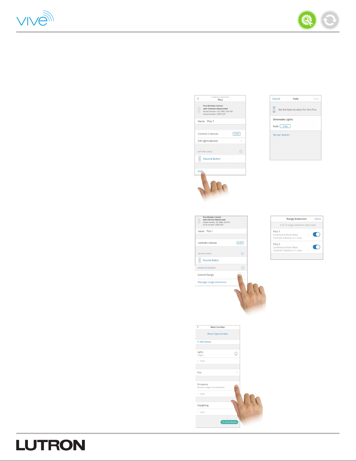
10. To set the fade duration for the Pico remote control, tap “Fade”.
This time specifies the length of the transition between the original
and target light levels of the dimmable lights assigned to the Pico
remote control.
Install
P/N 041571j
11. Extend the wireless range of a Pico wireless control if it is
controlling devices in multiple rooms or lights / devices beyond the
normal range. This ensures that far away lights / devices responds
to the Pico wireless control.
Note: This feature extends the wireless range of a Pico wireless
control to the full range of the hub that it is assigned to. It cannot be
used to control devices beyond the range of the hub.
Note: A hub will automatically extend the range of Pico wireless
controls if they fall under a recommended category; however, you
may choose to disable the range extension feature.
Note: A maximum of 15 Pico wireless controls can have their range
extended.
12. In a new room, if you have added multiple fixtures with sensors
to the Pico control, or a wireless daylight sensor, then you will be
given the option to enable all occupancy sensors to work together.
When working together, if any of the sensors detect occupancy,
then all lights associated with all of the sensors will turn on.
The option can be changed by tapping on the room, where
occupancy settings may be changed.
Continued on next page...
13
Page 14
Commissioning (continued)
Add Devices (continued)
Add a Sensor and Assign Devices
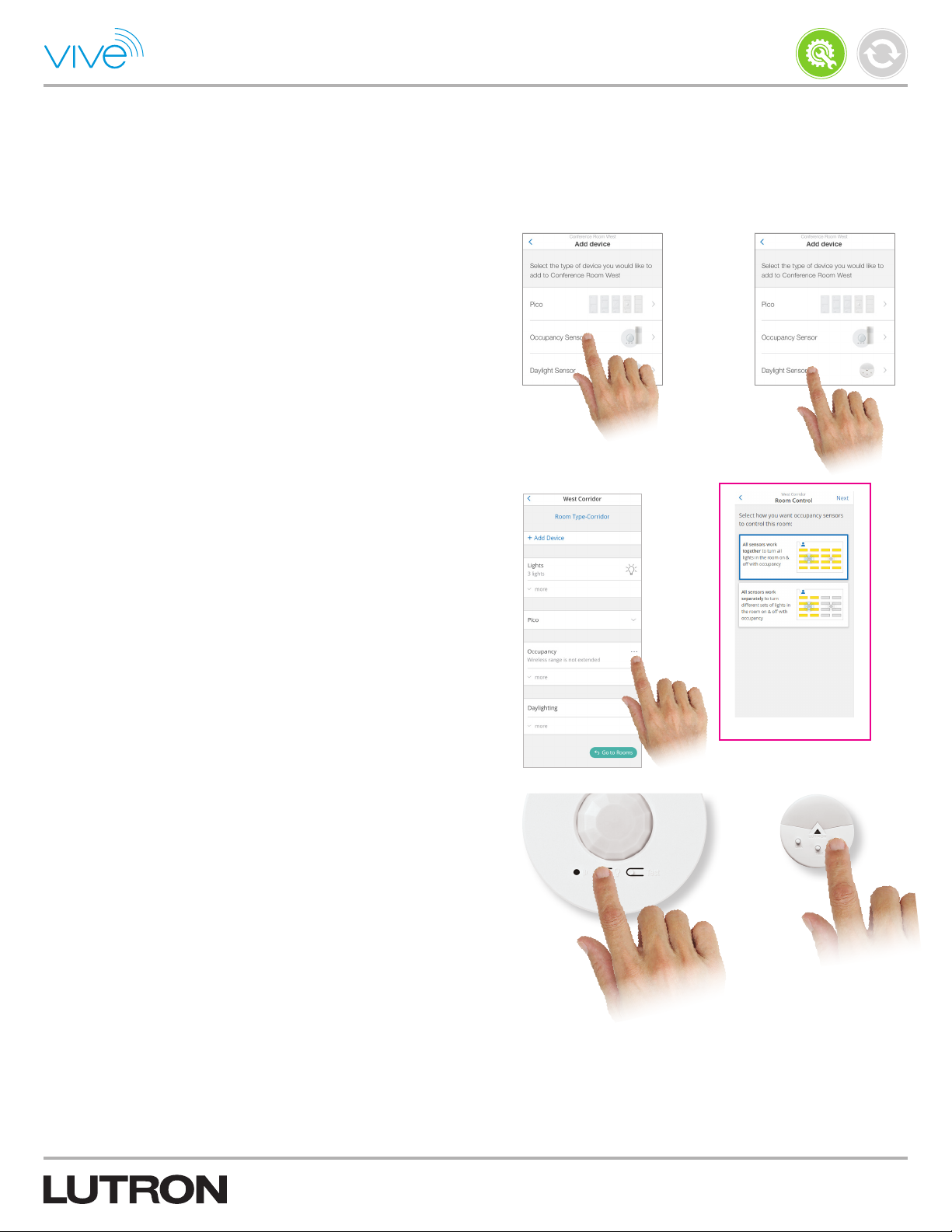
1. From the “Add device” screen, select the desired sensor type.
2. In a room with an existing wireless occupancy sensor, if you add an
additional wireless sensor, then you will be given the option to enable
all occupancy sensors to work together. When working together, if
any of the sensors detect occupancy, then all lights associated with
all the sensors will turn on.
Install
P/N 041571j
or
The option can be changed by tapping on the room, where
occupancy settings may be changed.
3. Press and hold the indicated button on the sensor for 10 seconds.
The system will perform another wireless signal measurement like it
did with the Pico remote control in the previous section.
or
Continued on next page...
14
Page 15

Commissioning (continued)
Add Devices (continued)
Add a Sensor and Assign Devices (continued)
4. Once the list appears, tap “FLASH” to identify the load and tap “+”
to add it.
Any loads already programmed to a Pico remote control are labeled
as such. This allows you to quickly identify which devices are
already part of the area.
Note: For wireless daylight sensors, the lights can be added
to different rows. There can be a different target brightness for
different rows of lights.
Note: For safety reasons, PowPak receptacle controllers and
PowPak CCO controllers will not flash their relay output when you
tap “FLASH”. Instead, these devices will rapidly flash the LEDs on
the front of the PowPak controller.
Install
P/N 041571j
Note: PowPak receptacle controllers cannot be assigned to a
daylight sensor.
Note: If there are many devices in the area, it may be easier to
rename them first before adding additional sensors. This allows the
fixtures to be identified easier when assigning them to sensors.
5. Enter the total wattage of each load in the appropriate “Wattage
(W)” field for each device. This is required to get accurate energy
data.
Note: In the case that Vive Integral Fixture Controls were added
that do not automatically report energy usage, it is possible to enter
a common wattage for them. It is also possible to enter the wattage
of each device individually by tapping “Set different wattages for
each light.”
6. Tap “Next” and rename the sensor. Tap “Done.”
15
Page 16

Commissioning (continued)
Add Devices (continued)
Add Devices Directly to the Hub
1. Tap “Add Device” at the room’s device screen.
2. Tap “I don’t have any of these devices in my room / area” and then
select the desired device.
Install
P/N 041571j
3. Press and hold the indicated button for 10 seconds. The screen will
show which button to press.
Continued on next page...
16
Page 17

Commissioning (continued)
Add Devices (continued)
Add Devices Directly to the Hub (continued)
Note: While adding an In-Wall Dimmer/Switch with sensor in the
room, additional lights/devices can be assigned to the sensor. The
occupancy of lights/devices added to the sensor will be controlled
by the sensor; however, the dimmer/switch will not control these
additional lights. It will only control its wired lights.
Install
P/N 041571j
4. Rename the device and enter the total wattage of each load in the
appropriate “Total Wattage (W)” field for each device. This is required
to get accurate energy data.
Note: The Vive software will automatically report energy usage
for fixtures with a PowPak fixture controller. Nothing needs to be
entered for these fixtures. If power for the fixture is not wired
through the PowPak fixture controller, the software will report 0 W
for that fixture.
Note: If additional devices are added to the sensor of an In-Wall
Dimmer/Switch with sensor, then an additional section with that
information will display on the device detail screen.
5. Tap “Done”.
17
Page 18

Find Devices not Showing up in
Discovery
Device Too Far Away
Sometimes a device cannot be found during the “Finding
Lights / Devices” step. Follow the steps below if you are having
difficulty finding a device that you would like to add to an area via a
Pico remote control or sensor.
1. On the “Select Lights” screen, tap “Start new search”.
2. Move a Pico remote control or sensor close to the device that you
are trying to add.
Note: Devices can be wired to multiple loads in an area. Move the
Pico remote control or sensor near the device, not the load.
Note: The Pico wireless control must be located within 30ft (9m)
through walls or 60ft (18m) line-of-sight of all devices that it
is controlling.
Install
P/N 041571j
3. Press and hold the indicated button on the Pico remote control or
sensor for 10 seconds. The system will perform a wireless signal
measurement and the device should be listed.
If you still cannot find the device, check the following:
• Verify that the device has power.
• Ensure that the device is properly wired.
• Sometimes large metal objects can decrease the signal strength of
a device making it appear further away. Move to the other side of
the room as that may make the device appear closer.
Unsupported Device
If the hub software does not support a specific device, you will get
an “Unsupported device” error message when trying to add that
device. Follow the steps in the Firmware Update section to update
the hub software. Once the hub software has been updated, add
the device to the hub.
Devices Set Up Without the Hub
If a light / device was manually assigned (button press method) to a
different device (e.g., Pico remote control, sensor), the light / device
will be shown in the discovered list but cannot be added until it
is restored to factory defaults. To do this, follow the steps on the
screen or in the installation instructions (provided with thedevice).
or
18
Page 19

Rename Devices
1. Tap “Rooms & Areas”, and select the area that contains the device.
2. For lighting controls, expand “Lights” and select the desired device.
For PowPak receptacle controllers and CCO controllers, expand
“Receptacles and CCO Modules” and select the desired device.
Install
P/N 041571j
3. Rename the device and tap outside of the “Name” field to save the
changes. A “Saved” confirmation note will be displayed.
Troubleshoot Devices
If a light / device is not behaving as expected, then try the
troubleshooting steps mentioned at the device detail screen.
Follow the steps below to navigate to the device detail screen:
1. Tap “Rooms/Areas”, select the area that contains the device.
2. Expand “Lights” and select the desired device.
3. Tap “Troubleshoot” to open screen with troubleshoot instructions.
4. Follow the instructions.
19
Page 20

Programming
Occupancy / Vacancy Sensor Settings
1. Navigate to the area that contains the sensor to be adjusted. Go to
“Occupancy” section of the screen and tap “...” and select “Sensor
Settings”.
In this menu, there are multiple settings that can be changed. See
below for details about these settings.
Status
Use the slider to enable or disable the occupancy / vacancy sensors
in that area.
Install
P/N 041571j
Sensitivity
Tap “Sensitivity” to adjust the sensitivity of the occupancy / vacancy
sensors. These settings will only appear if there is a PowPak fixture
controller with a fixture sensor in the area. Sensitivity for a Radio
Powr Savr sensor must be set locally on the sensor. Instructions on
how to do this will be shown on the software screen.
Note: Sensitivity should be increased if the sensors are not detecting
motion (e.g., lights turn off when people are in the room). Sensitivity
should be decreased if the sensors are detecting too much motion
(e.g., lights do not turn off after the timeout period).
Timeout
Tap “Timeout” to change the occupancy timeout for fixture sensors.
These settings will only appear if there is a PowPak fixture controller
with a fixture sensor in the area. Radio Powr Savr sensor timeouts
must be changed locally on the sensor. Instructions on how to do
this will be shown on the software screen.
2. Once the desired settings are changed, tap “Save” on the
respective screen.
Continued on next page...
20
Page 21
Programming (continued)
Occupancy / Vacancy Sensor Settings
(continued)
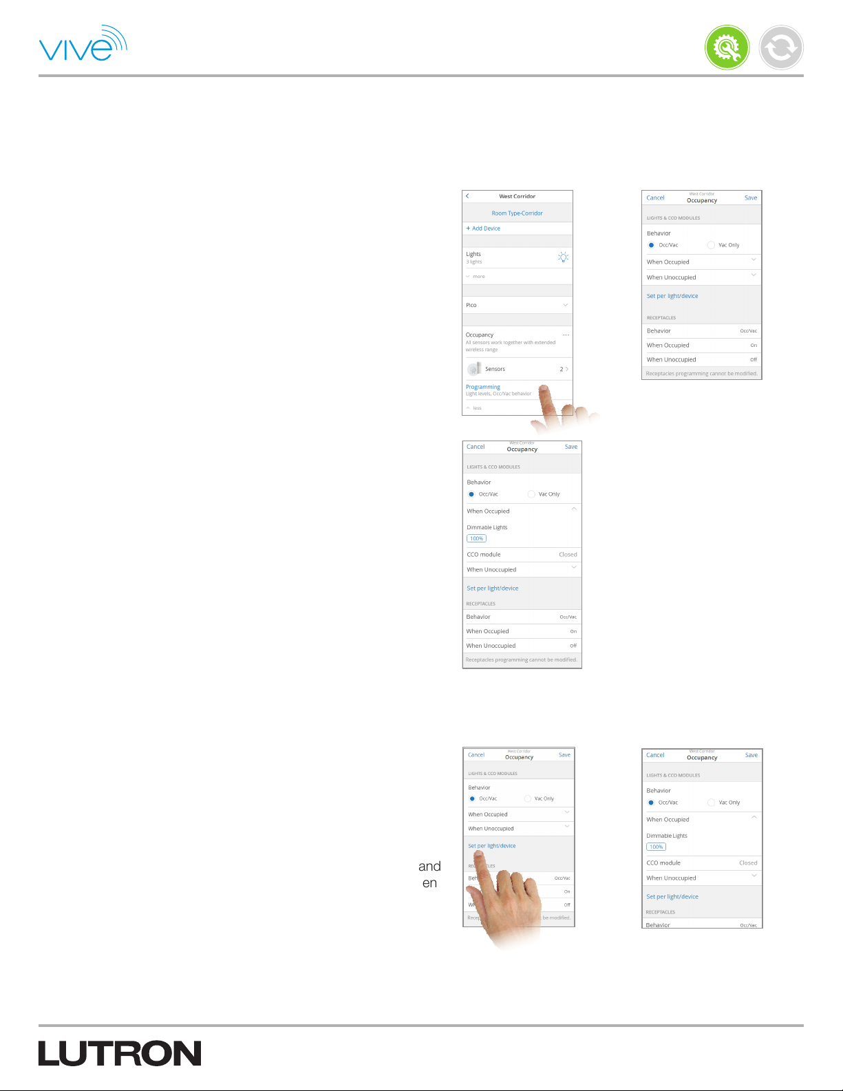
Occupancy Settings / Programming
• Navigate to the area that contains the sensor to be adjusted. Go to
“Occupancy” and select “Programming”.
• Refer to “Lights & CCO Modules” to adjust occupancy / vacancy
behavior, occupied / unoccupied levels, and other settings for lights
and CCO modules.
• Refer to “Receptacles” to view occupancy / vacancy behavior and
occupied / unoccupied settings for receptacles.
Note: The occupancy settings for a device type will only
display if there are corresponding devices being controlled
by an occupancy / vacancy sensor in that area. For example,
“Receptacles” will only be displayed if receptacles are being
controlled by an occupancy / vacancy sensor in that area.
Install
P/N 041571j
Occupancy / Vacancy Behavior
Set the “Occ / Vac” or “Vac Only” behavior in the area as desired.
This can be set the same for all the lights / devices in the area or it
can be set individually for each light / device.
• Occ / Vac = auto on; auto off
• Vac Only = manual on; auto off
Note: The RMJS-20R PowPak receptacle controller cannot be set
to “Vac Only”. It will always operate as “Occ / Vac” and the occupied
and unoccupied settings will always be “On” and “Off” respectively.
Note: The only two methods to enable / disable occupancy in a Vive
system are through this screen and via BACnet protocol.
Occupied / Unoccupied Levels
Adjust the occupied and unoccupied levels as desired for the
dimmable lights in the area. This can be same level for all dimmable
lights in the area or different levels for each dimmable light.
Note: Switched lights will always be set as “On” when occupied and
“Off” when unoccupied. CCOs will always be set as “Closed” when
occupied and “Open” when unoccupied.
Continued on next page...
21
Page 22
Programming (continued)
Occupancy / Vacancy Sensor Settings
(continued)
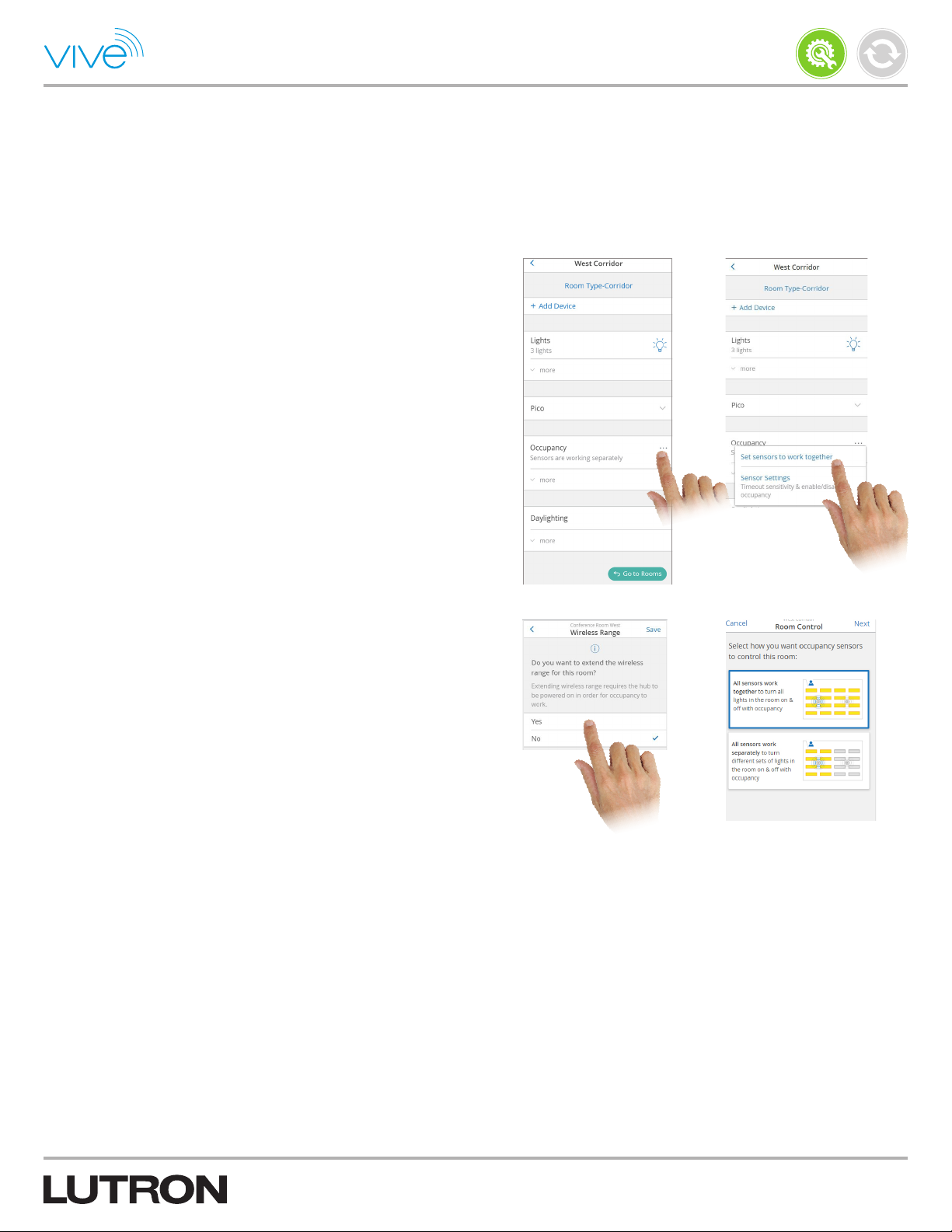
All Occupancy Sensors Work Together
Enable this setting for the room if you want all occupancy-controlled
lights/devices to turn on and off together when any occupancy
sensor in the room detects a change. Occupancy sensors added
later will also automatically control these lights/devices.
Tap “Set sensors to work together” and then “All sensors work
together” to enable this setting.
Install
P/N 041571j
In large or oddly shaped rooms, such as long hallways and open
offices, lights/devices may be outside the range of the occupancy
sensors. You can extend the wireless range so that all occupancy
sensors in the room can control any light/device in that room,
regardless of distance between these sensors and the device. You
can extend the wireless range of occupancy sensors for up to 14
rooms per Vive hub. Tap “Yes” on the Wireless Range screen to
enable this setting and select the room type.
22
Page 23
Programming (continued)
Occupancy / Vacancy Sensor Settings
(continued)
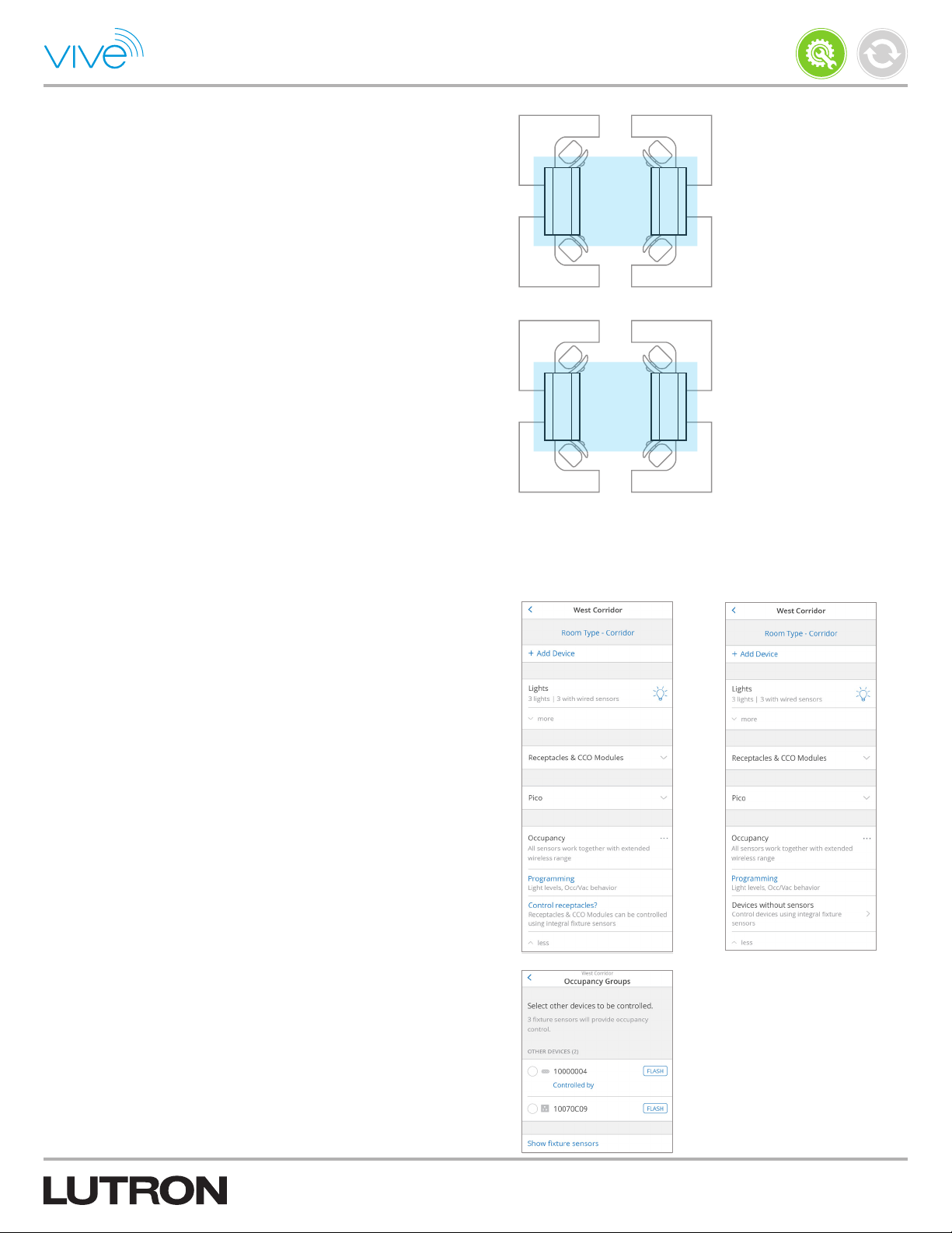
Occupancy Grouping
Below are two main applications of occupancy grouping with
fixture sensors.
Note: Occupancy grouping is not used with Radio Powr Savr
occupancy / vacancy sensors because devices are assigned to the
sensors directly. Also, devices can be assigned to more than one
sensor at a time for rooms with multiple sensors.
Install
P/N 041571j
Group 1
• Group fixture sensors together to form larger occupancy groups
(e.g., open office). When fixture sensors are grouped, all the lights
will turn on and off together. If one sensor sees movement, all the
lights will turn on. Conversely, all the sensors in the group must be in
the unoccupied state before the lights turn off.
• Allow control of devices other than fixture controls via fixture sensor
(e.g., private office where a fixture sensor controls both the fixture
and the PowPak receptacle controller).
To the right is an example of occupancy grouping. The four fixtures
are grouped into two separate occupancy groups based on the
furniture layout. Each group operates independently with the
corresponding fixture sensors and all four fixtures are part of the
same area.
Control Receptacles / CCO Modules Using
Occupancy Grouping
Note: If the fixture occupancy sensors are set to work together,
then they will all work as one occupancy group in the room.
In this case, expand the Occupancy section to find the “Control
Receptacles / CCO Modules” to open a screen to add devices (like
receptacles) to the occupancy group. Tap “Show fixture sensors” to
list fixture sensors which are working together in the room.
Group 2
Note: “Control Receptacles / CCO Modules” link on the screen will
not display if a few devices without sensors (receptacles, CCO
Modules ) are already being controlled by fixture sensors. Instead,
the “Devices without sensors” row will display in place of it.
23
Page 24
Programming (continued)
Occupancy / Vacancy Sensor Settings
(continued)
Control Receptacles / CCO Modules Using
Occupancy Grouping (continued)
Follow the steps below to create multiple different occupancy groups
using fixture sensors.
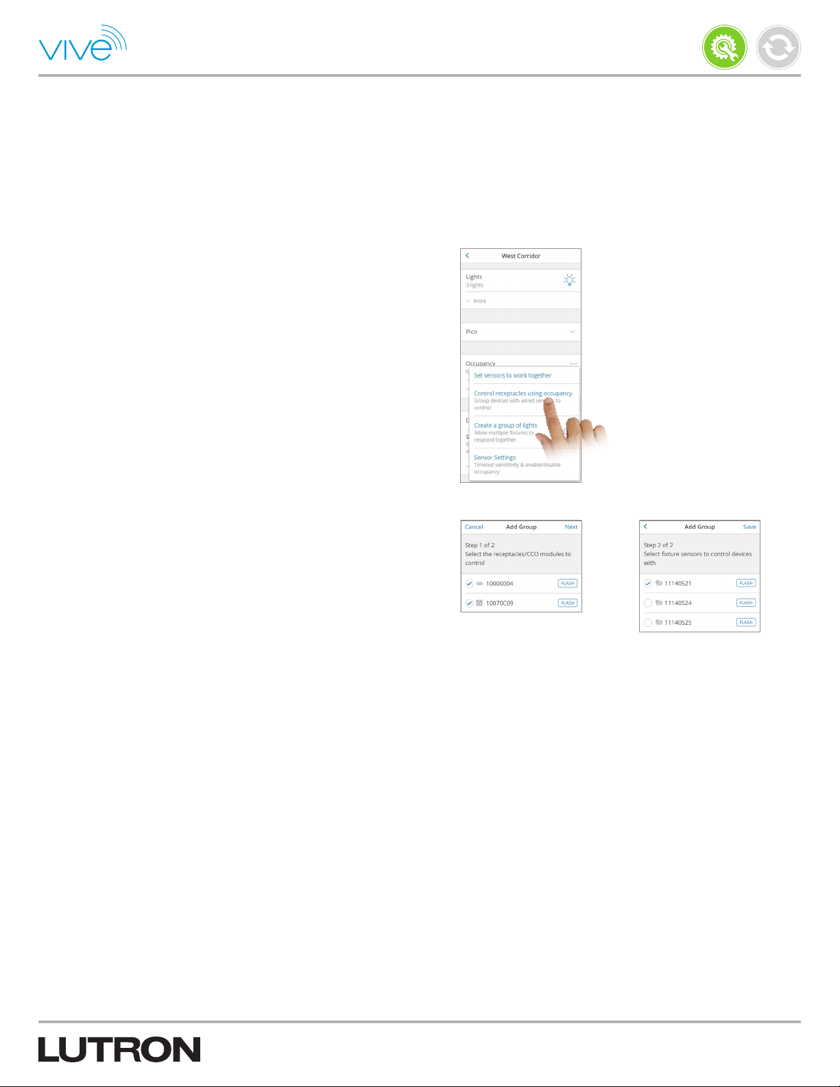
1. To create multiple occupancy groups using one or more fixture
sensors, first set sensors to work separately and then select “Control
receptacles using occupancy” if receptacles or CCO modules are
required to be grouped or “Create a group of lights” if only lights need
to be grouped with the fixture sensors.
2. To create an individual fixture sensor’s occupancy group when there
are wireless occupancy sensors working together in the room, first
set the sensors to work separately. If you want other devices to be
controlled by occupancy, then add them to any occupancy sensor.
Install
P/N 041571j
3. Follow the steps to select devices and fixture sensors to group. Now
all the fixture sensors in the group will work together to control the
grouped devices.
Note: In order to create an occupancy group, at least two
lights / devices and at least one fixture sensor must be added.
24
Page 25
Programming (continued)
Occupancy / Vacancy Sensor Settings
(continued)
Occupancy Dependency
When adding an occupancy sensor to a room / area, you select which
devices that sensor will control. You can also select devices in other
room / areas to be controlled by that same sensor. These devices will
now become dependent on the occupancy status of this sensor. For
example, users working in private offices may want the lights to stay
ON in an adjacent hallway.
When an occupancy sensor in one room controls lights in another
room, each room still has its own occupancy programming
(occupied / unoccupied levels, occ-vac / vac-only) and sensor settings
(enable/disable, sensitivity, timeout). For instance, if a sensor in one
room is programmed to affect lights in a second room, the sensor will
have no effect on the second room if Occupancy is disabled in the
second room.
Install
P/N 041571j
Follow these steps while adding an Occupancy sensor to a room, to
make that sensor control lights in another room:
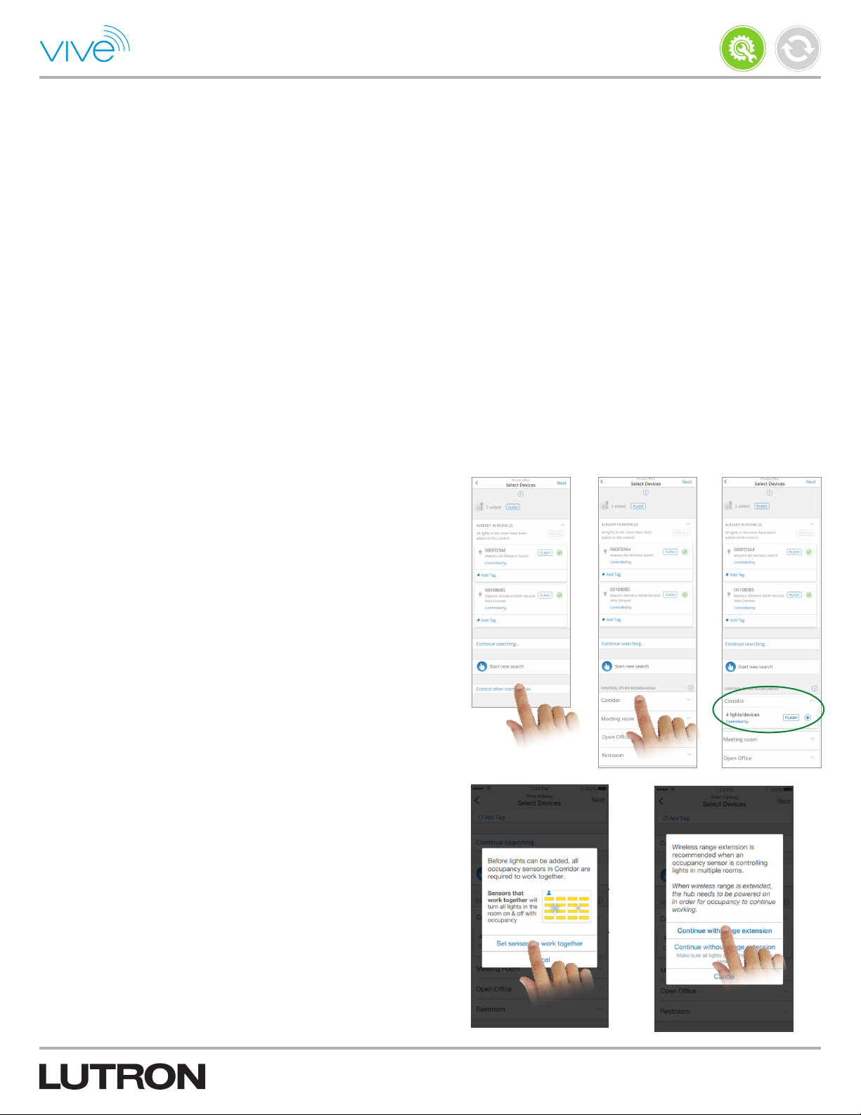
1. On the Select Devices screen, tap “Control other rooms/areas”.
Note: The “Control other rooms/area” option will be presented only
if other rooms already exist. If you add another room later, you can
come back to this screen and add it to this sensor.
2. Expand the room you wish to control and tap “+”.
Note: Depending on room configuration, your experience may vary.
3. If sensors are not already set to work together, you will be asked
whether to proceed, in which case you should tap “Set sensors to
work together”.
Note: Once occupancy sensors are set to work together, if any
sensor in that room detects motion, then all lights associated with
those sensors will turn on.
4. If occupancy range is not already extended in the room, you will be
asked how to proceed. Tap “Continue with range extension”, or make
sure that all lights in the room are within 98.5 ft (30 m) range before
tapping “Continue without range extension”.
Note: You may not use a sensor in one room to control lights in
a second room if that second room includes fixtures with wired
sensors or integral fixture controls (and they are enabled).
Note: You can make this sensor control more rooms later by editing
which devices are affected by this occupancy sensor.
Note: You can go to a room Occupancy section to see all sensors
(including from other rooms) which control that room.
25
Page 26

Tuning
High-end / Low-end Trim
1. Tap “Rooms & Areas” and select the desired area.
2. Expand “Lights”.
Install
P/N 041571j
3. Tap “Low-End trim” to adjust the low-end trim of the device. The
device will not go below this level. This can be set the same for all
devices or each device individually.
Note: Low-end trim is different than the minimum light level.
Low-end trim is the lowest level the load will dim down to before
turning off. The minimum light level is the level the load goes to
when commanded to turn off.
26
Page 27

Minimum Light Level
This setting should be used if you want the load to go to a specific
level when “turned off” but never actually turn off. This is primarily
used in paths of egress (e.g., corridors and hallways).
1. Tap “Rooms & Areas”, and select the desired area.
Install
P/N 041571j
2. Expand “Lights” and select the desired device.
3. Tap “This light should not turn off” and select the minimum light level
that the load should not dim below. Tap “Save”.
Note: The minimum light level is different than low-end trim. The
minimum light level is the level the load goes to when commanded
to turn off. Low-end trim is the lowest level the load will go before
turning off.
27
Page 28

Maximum Light Level
From the Vive software, you can set the maximum light levels for
lights, which will cap light levels to reduce brightness in the space
and save energy. The devices will not go above this maximum level.
Follow the below steps to set maximum light levels.
1. Tap the “More” menu on the main dashboard of the Vive software.
Install
P/N 041571j
2. Tap “Maximum Light level” to set the levels.
3. Set the maximum light levels for all dimmable lights. To set devices
to different levels by area, tap “Set per room / area”.
4. To set devices to different maximum levels by device in an area, tap
“Set per light” in that area.
28
Page 29

Daylighting
Daylight harvesting reduces the use of artificial lighting when daylight
is available in order to reduce energy consumption. This applies to
all operations, including all Pico button presses. Daylight calibration
is either done automatically (fixture sensor) or manually through
button presses (Radio Powr Savr daylight sensor). Details on
daylight sensor calibration are covered below.
Best Practices
1. Calibrate space first for best results.
• Perform calibration when the space is receiving adequate, indirect
sunlight. Do not calibrate when there is direct sunlight entering the
space or when there is low sunlight.
• Perform calibration after all of the furniture or equipment has been
moved into the space and after all painting has been completed.
• If a customer has specific requirements for illumination,
measurements using a light meter may be required to adjust the
light levels to match these requirements. After noting the required
level, take lux measurements with a light meter at work surface
height [typically 91.4 cm (3 ft) above finished floor] and directly
under the row of fixtures being tuned.
Install
P/N 041571j
or
2. If the brightness still does not meet expectations after calibration,
set the target brightness level to fine tune the light level in the
space.
Individual Fixture Sensors
• Fixture sensors will automatically perform daylight calibration the first
time the sensor goes to the unoccupied state. The fixture sensor is
both an occupancy and daylight sensor.
• A fixture sensor will only control the PowPak fixture controller that
it is attached to. Daylight information cannot be shared from one
individual fixture sensor to other devices.
• If a Radio Powr Savr daylight sensor is assigned to a PowPak
fixture controller, the daylight sensor function of the fixture sensor
will be disabled.
Continued on next page...
29
Page 30

Daylighting (continued)
Radio Powr Savr Daylight Sensors
Radio Powr Savr daylight sensors must be calibrated manually.
Refer to these sections of the Radio Powr Savr daylight sensor
installation instructions: Calibration, Testing the Daylight Sensor, and
Tuning the System.
Note: You do not need to press a button on PowPak devices
because they will automatically enter calibration mode.
Instead of pressing and holding the “Cal” button on the sensor, you
can shine a green laser (available at hardware or office supply stores)
on the sensor two times to put it in calibration mode. This is the
same procedure used for association.
WARNING! Eye Injury and/or Blindness Hazard. May
!
Result in Serious Injury or Death. Avoid direct eye
exposure to laser beam.
• Use of laser pointer is NOT recommended for use with Lutron
products located near reflective surfaces.
• Do NOT aim or shine laser pointers at any person, pet, vehicle,
or aircraft directly, or through reflection by mirrors or other shiny
surfaces. Do NOT view the laser beam through binoculars,
magnifying glass, or other optical devices.
• Do NOT allow children to use laser pointers.
• Read and follow the laser pointer manufacturer’s instructions
on safe use. In the event of injury, get medical attention immediately.
Install
P/N 041571j
Multi-row Daylighting
To the right is an example of multi-row daylighting using a Radio Powr
Savr sensor. To complete a similar setup, follow the steps below.
1. In the Vive software, assign all fixtures to the daylight sensor.
2. Manually adjust the devices for all rows to achieve the desired
foot-candle(fc) level.
Note: It may be a challenge to physically find where the PowPak
devices are located and manually adjust them to reach the desired
foot-candle level. To alleviate this challenge, you can assign a
2BRL Pico remote control to each PowPak device participating in
daylighting so that you can adjust the level remotely. After daylighting
has been calibrated, you can remove the 2BRL Pico remote controls
from the Vive system database.
Continued on next page...
Row 1 Row 2
Window
30
Page 31

Daylighting (continued)
Multi-row Daylighting (continued)
3. To adjust the daylighting settings, navigate to the area dashboard
that contains the daylight sensor. Expand “Daylighting” section and
select “Settings”.
4. Tap the daylight sensor to be calibrated and read “Getting started”.
Tap “Next” and follow the instructions to perform calibration.
Note: Check out “Best Practices” in the beginning of
this section for tips on calibrating the sensors.
Install
P/N 041571j
5. If brightness still not does meet expectations after calibration, tap
“Target Brightness” to adjust the target brightness of the room.
These changes are live so that you can view the changes and fine
tune until your space is at your desired level. If the daylight in the
space is at a high level during adjustment, changes may not be
perceivable. You can adjust and save target brightness of all lights or
lights connected to a specific sensor.
Note: This option only displays if a wireless daylight
sensor has been added to the room.
6. Use the slider to Enable or Disable daylighting in that area.
7. Tap “Allow daylighting to turn off dimmable lights” to allow or
prevent dimmable lights to turn off due to daylighting. If “Yes” is
selected, the lights may turn off if enough daylighting is present
in the room. If “No” is selected, daylighting will not turn off the
dimmable lights, but it will still dim lights to the low-end trim level.
This setting will not affect switches and CCOs added in the room.
Note: The low-end trim level can be adjusted in Tuning.
Note: The dimmable lights which were turned OFF when the daylight
setting was changed, will only take effect when daylight in the space
is insufficient. These changes are not made in real time.
31
Page 32
Schedules
The hub contains a built-in timeclock that can schedule an event by
time of day or astronomic time.
Note: Create and program all of the individual areas before creating
timeclock schedules.
Create Schedule
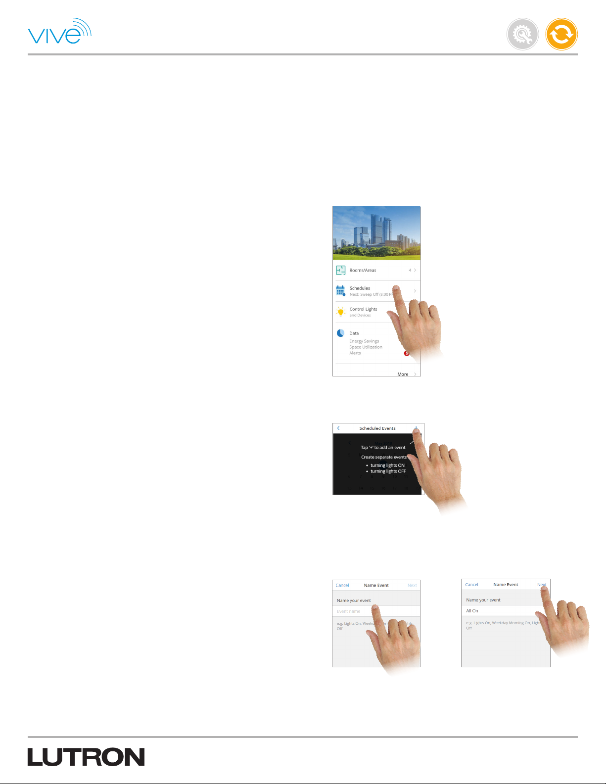
1. Open the “Schedules” menu on the main dashboard of the
Vivesoftware.
Maintain
P/N 041571j
2. Tap “+” to add a schedule. You can create many separate timeclock
schedules and each one is uniquely programmed.
3. Name the schedule so that it describes the intended programming
(e.g., AllOn - Morning).
Continued on next page...
32
Page 33
Schedules (continued)
Create Schedule (continued)
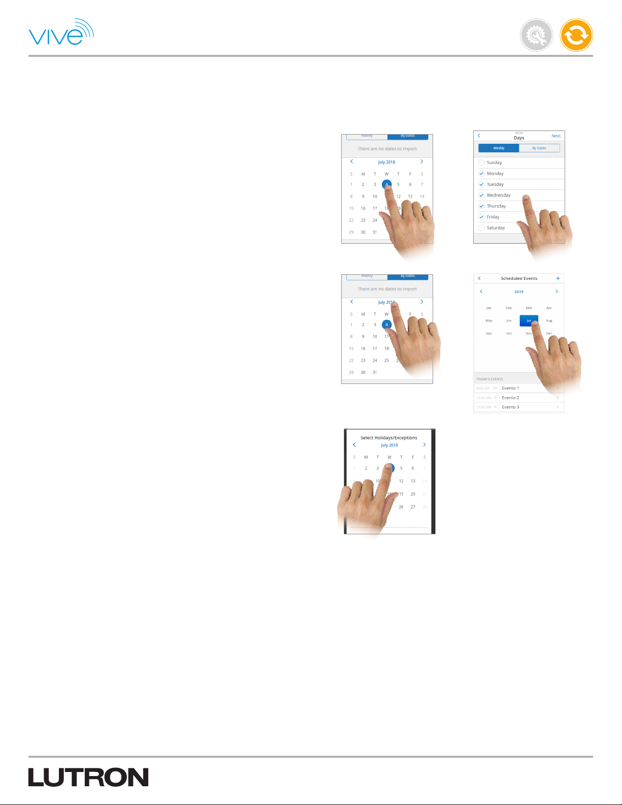
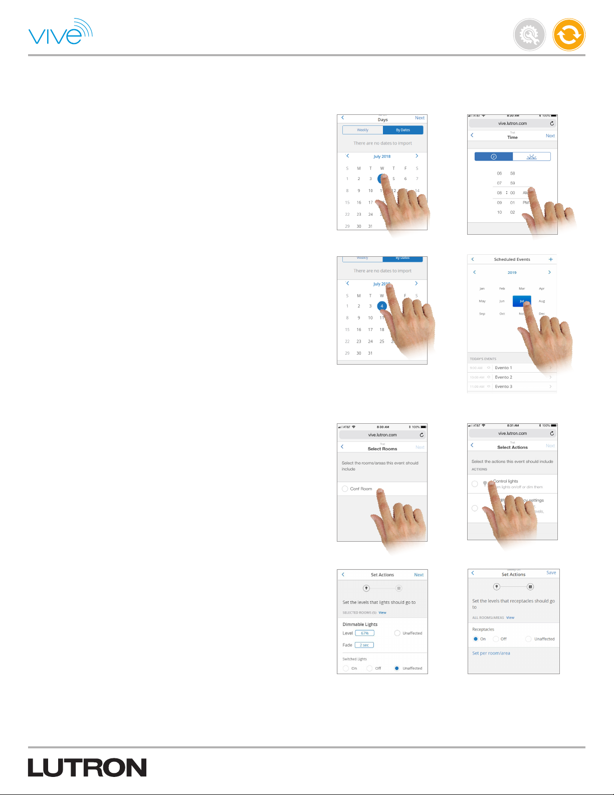
Note: You can create “Weekly” events which will run on selected
weekdays or “By Dates” events which will run only on the selected
dates.
4. If you are creating a Weekly event then adjust weekdays, select start
date, end date & Holidays/Exception dates and tap “Next”. Any day
of the week can be selected.
5. Click on the Month or Year to quickly jump forward to a date in the
future.
Maintain
P/N 041571j
6. Events will not run on the selected Holidays/Exceptions.
Note: On the Select “Holiday/Exception” screen, you can import
Exception dates from other events. Grayed out dates on calendar
represents that the event will not run on these dates.
Schedules (continued)
Create Schedule (continued)
Continued on next page...
33
Page 34
Schedules (continued)
Create Schedule (continued)
7. If you are creating a “By Dates” event, then select dates on which
you want to run the event and tap “Next”. Select the time you wish
the event to start.
8. Click on the Month or Year to quickly jump forward to a date in
the future.
Maintain
P/N 041571j
9. Select the rooms/areas that the event should include.
10. Select the actions this event should include.
11. Indicate the levels that the lights, receptacles, and CCO modules
should go to when this event occurs.
Note: You may also choose to change the fade duration for this
event. This time specifies the length of the transition between the
original and target light levels of the dimmable lights in the event.
Continued on next page...
34
Page 35
Schedules (continued)
Create Schedule (continued)
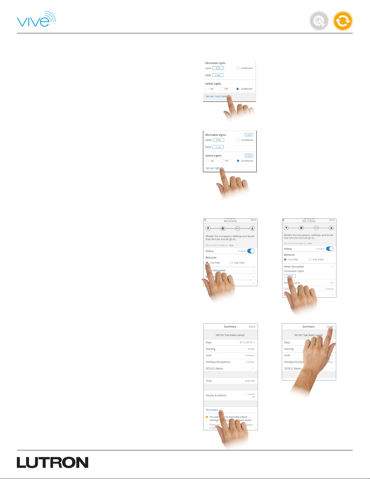
12. To set devices to different levels by area, tap “Set per room/area”.
13. To set devices to different levels by device in an area, tap “Set per
light” in that area.
Maintain
P/N 041571j
14. Set the occupancy settings and levels for this event and tap “Save”.
Note: Once an event is triggered, it will modify the occupancy
settings of individual areas.
15. If desired, tap “Test event” to test the schedule. Tap “Done” to save
the schedule.
Note: The “Test event” will test the light level transitions. Changes
made to Occupancy Settings will not be shown in the test event.
35
Page 36
Schedules (continued)
Modify and Test Schedules
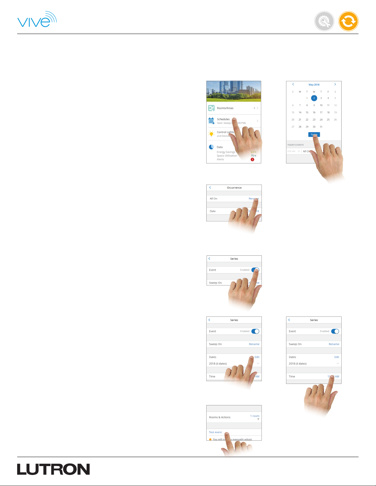
1. After creating a schedule, navigate to the “Schedules” screen. You
will see the list of scheduled event(s) in the calendar view. You can
select a different date to see scheduled events for a date. Tap the
desired schedule to modify or view its details.
Note: A recurring icon will display against events which are
scheduled for multiple days/dates. Tapping on recurring events
will ask you to open “This occurrence” or “Entire series.” “This
Occurrence” will open event details of a particular date and “Entire
series” will open the details of complete series including start date,
end date and exceptions. Modifying an Occurrence will modify
event for an Occurrence only.
Maintain
P/N 041571j
2. You can do any of the following:
a. Enable or disable the entire event series by moving the “Status”
slider. This enables or disables the schedule on all programmed
days, not just one specific day.
Note: Delete Occurrence if you do not want to run an event on a
date.
b. Modify the name, day, dates, time, Holidays/Exceptions and
Rooms & Actions affected by the schedule on this screen.
Note: If it is a “Weekly” event then click on “Edit” dates to modify
weekdays, start & end date, and exceptions. If it is a “By Date”
events, then tap on “Edit” dates.
c. Tap “Test event” to test the programmed schedule. This will
activate the schedule so you can see what the space will look like
when the event occurs.
36
Page 37
Alerts
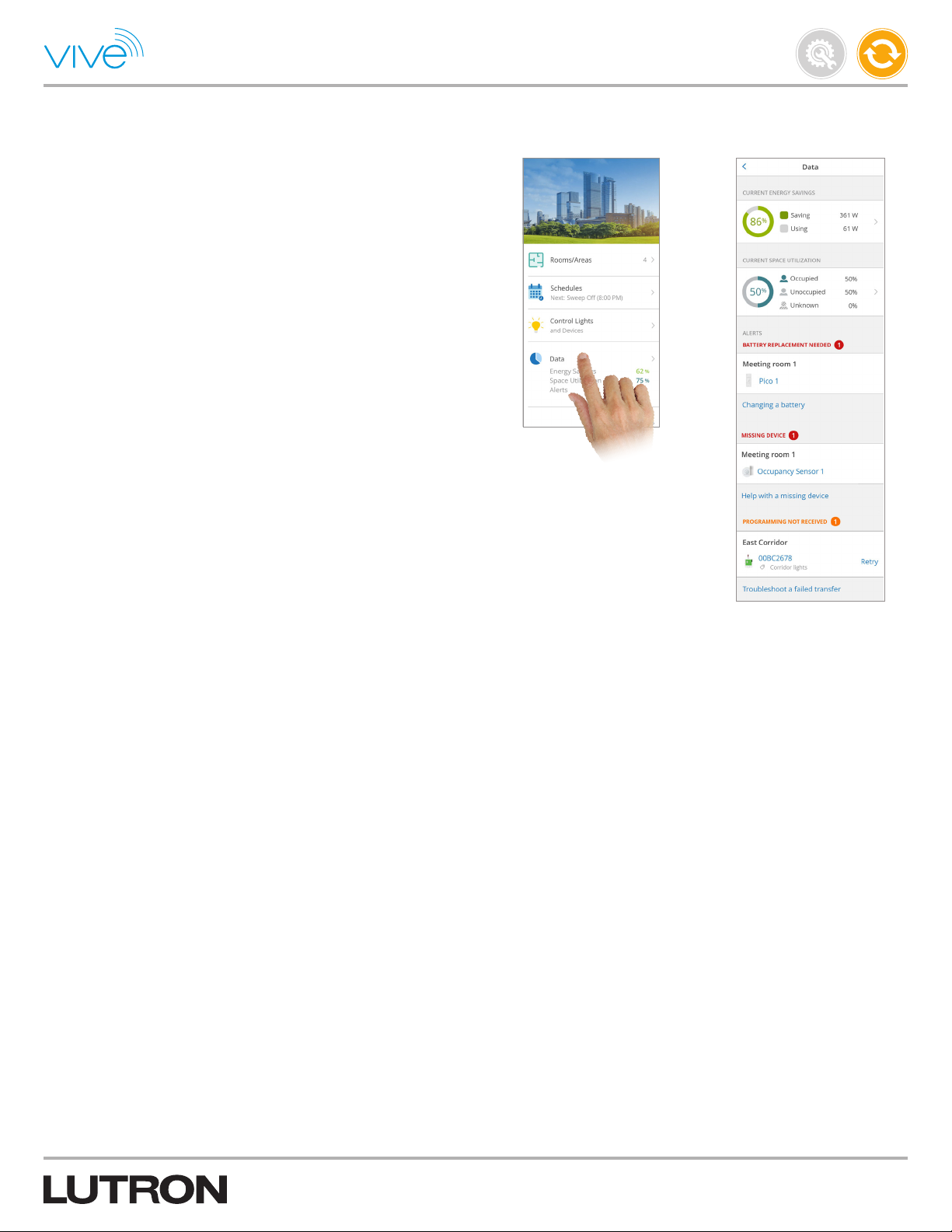
Alerts displays run-time issues which may prevent devices from
operating as expected.
View Alerts
Tap “Data” on the main dashboard of the Vive software to open the
screen with details on current energy savings, space utilization and
alerts.
Fixing Alerts
If you need help resolving an alert, tap on the provided links in each
section to get step-by-step guidance.
Alert Types
• Battery Replacement Needed: The device either has low a battery
or the battery has died.
• Missing Device: The hub cannot communicate with the device.
• Programming Not Received: The hub had attempted to send
programming to the device but was unsuccessful. Retry or perform
troubleshooting steps and then retry.
Maintain
P/N 041571j
37
Page 38
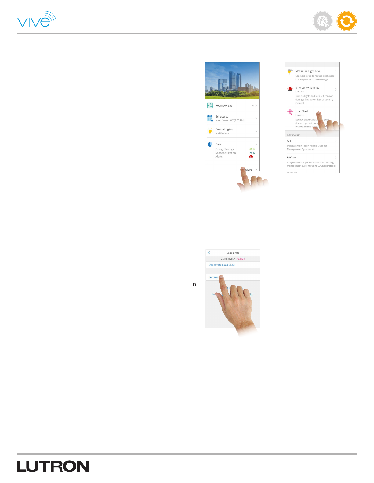
Load Shed
Load shed is a feature that reduces the overall lighting load in a
system in response to an external signal (typically from a
utility company).
Note: Add all devices to the system before configuring the load
shed settings. If a device is added to an area after the load shed is
configured, the device will need to be set up with the load shed.
1. Tap the “More” menu on the main dashboard of the Vive software.
2. Tap the “Load Shed” menu on the main dashboard of the
Vive software.
Maintain
P/N 041571j
2. Tap “Settings” to modify the settings for load shed events.
Note: Load shed can be manually activated from the “Settings”
screen, automatically activated through the contact closure input on
the back of the hub, or automatically activated via BACnet.
Note: There is only one profile available for load shed. The settings
that are modified will apply each time load shed is activated.
Continued on next page...
38
Page 39
Load Shed (continued)
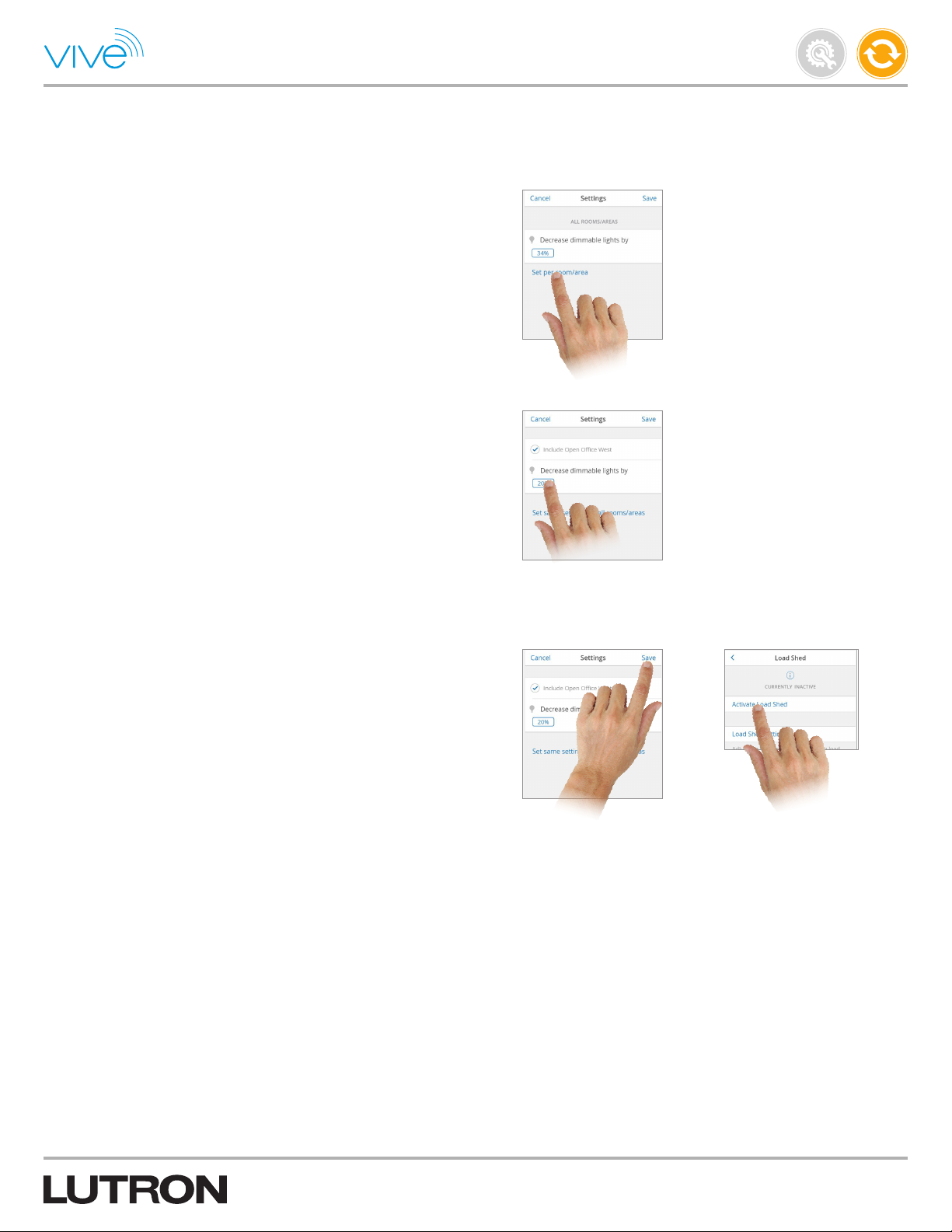
3. There are two options that can be modified for the load shed profile:
a. By default, all areas will participate in a load shed event. Tap “Set
per room / area” to select which specific areas participate in the
event.
b. For each area that participates in the load shed event, you can
set the percentage that dimmed loads decrease. Also, you can
set whether switched loads turn off or remain unaffected by a
load shed.
Note: After a switched load is turned off by load shed, the user
can override the load shed by manually turning the switched
loads on. The switched loads will not react to load shed until load
shed is deactivated and activated again.
Maintain
P/N 041571j
4. Tap “Save” and tap “Activate load shed”.
Note: When load shed is activated, it creates a scaled cap on the
maximum light level of all dimmed loads. Regardless of what light
level the dimmed load is currently at, it will be reduced when load
shed is activated. For example, if a dimmed load is at 50% when a
load shed profile of 20% is activated, the dimmed load will dim to
40%. The user can brighten the dimmed load to a maximum of 80%
while load shed is active.
39
Page 40
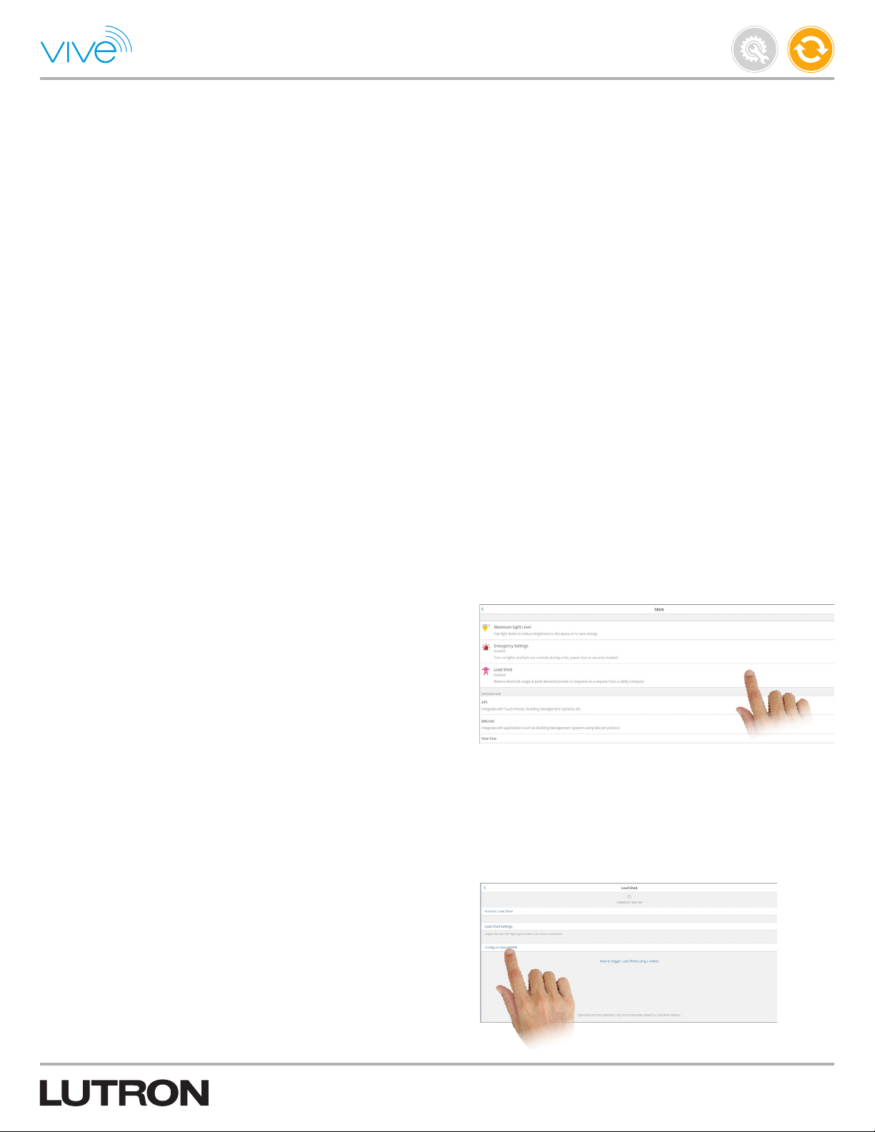
OpenADR
OpenADR is an energy code compliance feature that enables you to
opt-in to automatic triggers of load shedding events from your utility
company during peak hours.
To configure OpenADR, please note the prerequisites required for
each hub:
1. Ensure each hub has an internet connection and an Ethernet cable
is plugged into the hub.
2. Ensure your utility company is OpenADR 2.0b certified.
3. Contact your utility company to gather the following information:
a. OpenADR 2.0b Endpoint URL
b. Process to acquire OpenADR security certificates for your hub(s)
Your utility company might optionally provide a:
c. Virtual Top Node (VTN) ID
Maintain
P/N 041571j
d. Virtual End Node (VEN) ID
e. Market Context
f. VEN Name
g. Registration ID
Once prerequisites are met, follow the steps below to configure
OpenADR for each hub:
1. On the main dashboard in the Vive software, tap “More” and then
“Load Shed”.
2. Select “Configure OpenADR” to initiate setup.
40
Page 41
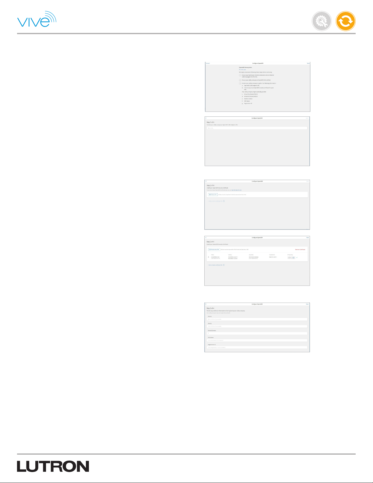
OpenADR (continued)
3. After confirming that the prerequisites are met, input the URL given
by your utility company.
4. Upload the OpenADR Security Certificate and private key you
acquired by following the process given to you by your utility
com p a ny.
Maintain
P/N 041571j
5. Enter any additional information that your utility company has
provided to you. Some or all of these fields may not be used
depending on your utility company.
41
Page 42

OpenADR (continued)
6. Confirm that all the information provided by your utility company has
been captured accurately and then click “Register”.
a. If your Registration has been successful, you will receive a
confirmation that includes the hub’s VEN ID. Your utility company
may require that you provide this to them.
b. If your Registration has failed, an error message will appear with
additional information on why registration had failed.
Maintain
P/N 041571j
To make changes to the OpenADR settings, return to the “Load
Shed” menu of the Vive software, select “OpenADR settings” and
then select “Edit settings”.
42
Page 43

Emergency
Emergency settings allow you to configure the level that lights will go
to in the event of an emergency. These lights, while in emergency
mode, will not respond to sensors or button presses from Pico
remote controls and will remain at their emergency levels. While in
normal operation, the lights will respond normally to commands
from Pico remote controls and sensors.
Follow the steps below to program emergency settings:
1. From the main dashboard in the Vive software, tap “More” and then
“Emergency Settings”.
Note: “Emergency Settings” will only display if there are Emergency
lights added to your hub.
2. Tap “Emergency Settings” to set emergency settings.
3. All Emergency lights (red PowPak modules) will automatically follow
default settings, which can be modified from the Emergency setting
screen.
Maintain
P/N 041571j
Cloud Backup
Cloud backup is available only on the Lutron Vive app. If user has
allowed cloud storage while creating a Vive project, then the hub’s
programming is automatically backed up and stored on the cloud.
It helps to restore your system in an event that the hub needs to be
replaced.
Follow the steps below to view Cloud Backup:
1. From the main dashboard in the Vive software, tap and then tap
“Cloud Backup”.
Note: To restore the backup on the Vive Hub, please contact Lutron
Customer Assistance.
43
Page 44

BACnet
BACnet is used for integration into a Building Management System
(BMS). For a list of control points available through BACnet and
details related to implementation of this standard in Vive systems,
refer to the Protocol Implementation Conformance Statement (PICS).
The PICS can be found at www.lutron.com/vive and is available
in the hub via BACnet ID Report. BACnet is only available with
premium hubs (HJS-2 models). Integration is only allowed via wired
Ethernet.
Note: The hub uses BACnet/IP protocol to communicate. There are
other forms of BACnet communication (e.g., BACnet MSTP) but the
hub will not directly communicate to these other protocols. There
are third party devices that can convert one protocol to another.
Note: Before modifying any of the BACnet settings, coordinate
with the BMS integrator to ensure settings are applied that allow
integration into the BMS BACnet network.
Refer to the API integration section in this document to use API for
your building management system.
Maintain
P/N 041571j
Settings
1. From the main dashboard in the Vive software, tap “More” and
then “BACnet”.
2. Enable or disable BACnet as desired. BACnet is disabled by default.
Note: The hub is a BACnet virtual router because it relays
commands between the physical network that the hub is connected
to and the virtual network of all the areas in the Vive system. Each
area in the Vive system is a virtual BACnet device.
Continued on next page...
44
Page 45

BACnet (continued)
Settings (continued)
3. “Network number” field
This is the virtual network number and can be modified as desired.
The hub will automatically take the network number of the physical
network it is connected to. The physical and virtual network
numbers must be different.
Note: There can be multiple BACnet hubs on the same network. By
default, the hubs will all have their virtual network numbers set to “1”
which will cause conflicts on the network. Set the virtual network
number of each hub to a unique number. The allowable range is
1 – 65534.
4. “Device Instance” field
This is the BACnet ID that the BMS will use to communicate with
the hub. All of the areas created via the hub will have IDs that are
generated sequentially after the “Device Instance”. The allowable
range is 0 – 4194302.
Maintain
P/N 041571j
Note: Each device must have a unique instance ID on a BACnet
network. A single hub can have hundreds of unique IDs (e.g.,
areas). It is critical to coordinate the IDs between the hubs and
any third party BACnet devices that may be on the same network.
Coordination with the BMS integrator is critical. Unless specific IDs
are supplied by the integrator, it is recommended to offset the base
“Device Instance” by 1000 for each hub on the network. This will
ensure there are no repeat IDs.
5. Tap “Edit room BACnet IDs” to change the area IDs. Use the “Device
Instance” ID as a base address. The allowable range is 0 – 4194302.
Continued on next page...
45
Page 46

BACnet (continued)
Settings (continued)
6. Tap “Advanced Options” to modify additional BACnet settings.
a. “Port” field
This is used for inbound and outbound UDP communication on
the network. By default it is 47808 but can be changed if desired.
b. “BBMD IP Address” field
This is the IP address of the BACnet Broadcast Management
Device (BBMD). There are several BACnet commands that are
sent as broadcast messages and those are typically blocked by
equipment on IT networks. BBMDs are used to route broadcast
traffic from one BACnet network to another. The hub supports the
ability to register as a foreign device with a BBMD by entering the
IP address of the BBMD into this field.
Maintain
P/N 041571j
c. “BBMD Time to live (secs)” field
This is the amount of time (in seconds) that a command routed by
a BBMD will live on a network before it is deleted.
7. Tap “BACnet ID Report” to generate a report that contains the
BACnet IDs for all of the BACnet devices in the Vive system. This will
generate two PDF documents:
a. A list of the specific BACnet IDs with the Areas / Rooms they are
assigned to.
b. The PICS statement which covers the types of information that
can be shared and the commands that can be sent to those
areas.
These documents should be sent to the BMS integrator.
Note: Each area in the Vive system is a virtual BACnet device.
46
Page 47

API Integration
The API enables you to integrate the hub with other applications,
such as a Touch Panel or a Building Management System. API is
only available with premium hubs (HJS-2 models). Integration is only
available via a wired Ethernet connection.
In the RESTful protocol supported by this API, each object in the hub
is referred to as a “Resource”, which may be controlled or monitored.
Examples of Resources include rooms, devices and zones.
Instructions to Integrate
Follow the steps below to program emergency settings:
1. From the main dashboard in the Vive software, tap “More”.
Maintain
P/N 041571j
2. Tap “API” to add an integration on this hub.
3. Tap “Add” for each unique Touch Panel and Software API integration
on this hub.
4. If a Touch Panel is selected, select the rooms which it would control.
Continued on next page...
47
Page 48
API Integration (continued)
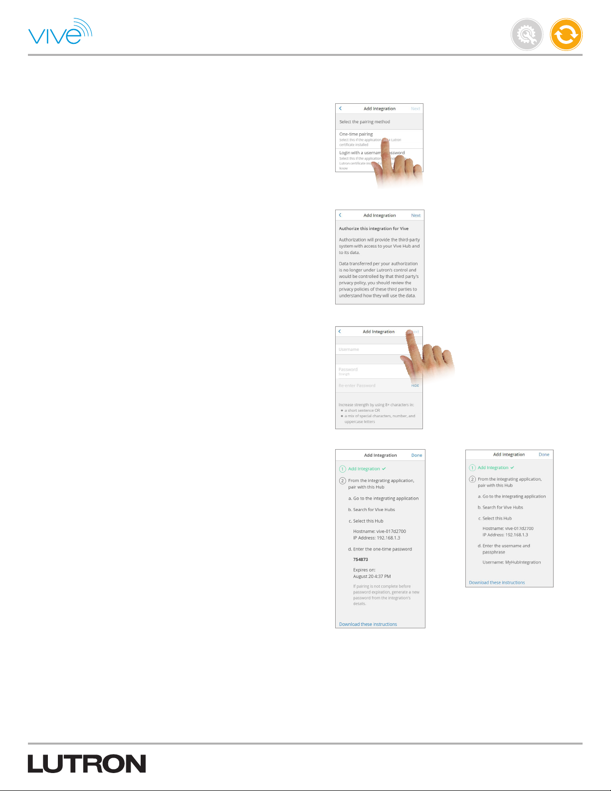
5. Choose the pairing method for the integration.
Note: “One-time pairing” should be selected if the integrating
device is partnered with Lutron and has a Lutron certificate installed
on it. “Login with a username / password” should be selected if the
integrating device or application does not have a Lutron certificate
installed. If you are not sure which to select, reach out to the
company of the integrating device.
6. Authorize integration for the Vive hub by selecting “Next”.
7. Set username and password if the selected pairing method was
“Login with a username / password” and tap “Next”.
Maintain
P/N 041571j
8. Follow the instructions on the screen to pair the integrating
application with the hub. The pairing instructions differ depending
upon if “One-time pairing” or “Login with a username / password”
method was selected.
Note the one-time password for “One-time pairing” method
integration. You can also download these instructions to use while
integrating the application.
Continued on next page...
48
Page 49
API Integration (continued)
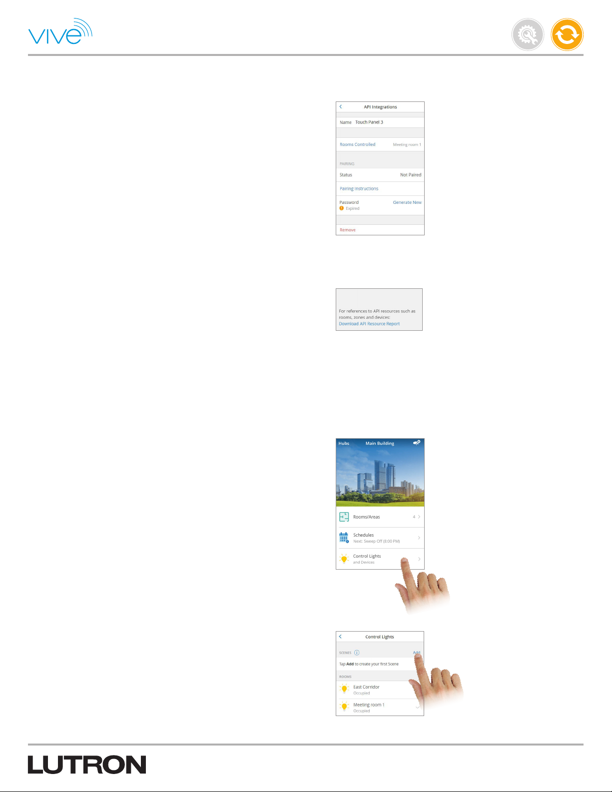
9. From the integrating application, pair the hub. When prompted, enter
the password details.
Note that for “One-time pairing” intgeration, one-time passwords
may only be used once and within 48 hours of generation. If it has
expired, return to the integration on the hub and generate a new
password.
10. Configure the integrating application. To configure the integrating
application offline (when not connected to the hub), tap “Download
API Resource Report” on the API integration screen.
Maintain
P/N 041571j
Scenes
From the Vive software, you can control lights and devices in a single
room or multiple rooms using scenes.
Create a Scene
1. Tap the “Control Lights” menu on the main dashboard of the
Vive software.
2. Tap “Add” to add a Scene.
Continued on next page...
49
Page 50
Scenes (continued)
Create a Scene (continued)
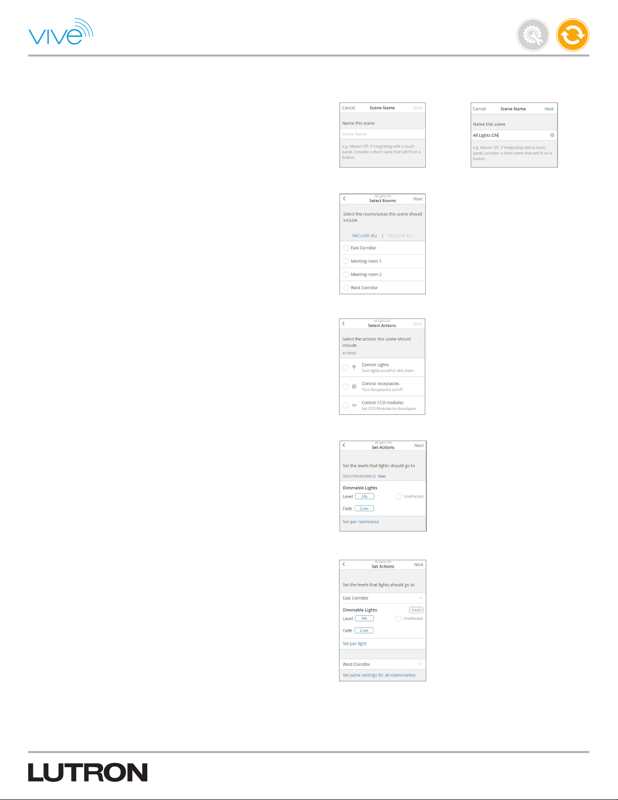
3. Name the scene so that it describes the intended programming
(e.g., All Lights ON).
4. Select the rooms / areas that the scene should include.
5. Select the actions this scene should include.
Maintain
P/N 041571j
6. Indicate the levels that the lights, receptacles, and CCO modules
should go to when this scene activates.
Note: You may also choose to change the fade duration for this
scene. This specifies the length of time for the transition between the
original and target light levels of the dimmable lights for this scene.
7. To set devices to different levels by area, tap “Set per room / area”.
8. To set devices to different levels by device in an area, tap “Set per
light” in that area.
Continued on next page...
50
Page 51
Scenes (continued)
Create a Scene (continued)
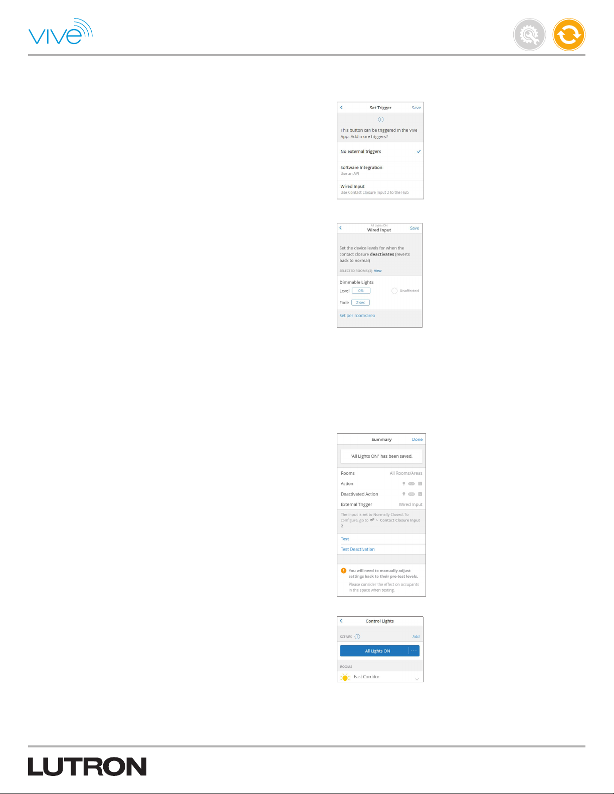
9. Once created, the scene can be triggered using a button in the Vive
software. If required, select an external trigger to activate this scene.
a. Select “Software Integration” if API intgeration will be used to
activate the scene.
b. Select “Wired Input” if the hub’s second contact closure input
(CCI 2) will be used to activate the scene.
10. If “Wired input” (CCI 2) is selected, then set the device levels for
when the contact closure input deactivates.
Maintain
P/N 041571j
11. Tap “Save” to save the scene.
12. If desired, tap “Test” to test the scene. For the “Wired Input”,
deactivation settings can also be tested using “Test Deactivation”.
Tap “Done” to continue.
13. Once created, press the button for that scene to activate
the sequence.
51
Page 52
Control and Monitor
From the Vive software, you can control and monitor many aspects
of the system. Lights and devices for individual rooms can be
controlled using the virtual control buttons for lights and devices.
“Scenes” can be used to control lights and devices across multiple
rooms.
The Vive software can also be used to monitor current energy
savings, space utilization and alerts for any missing or low battery
devices in the system.
Please see the following section for more details.
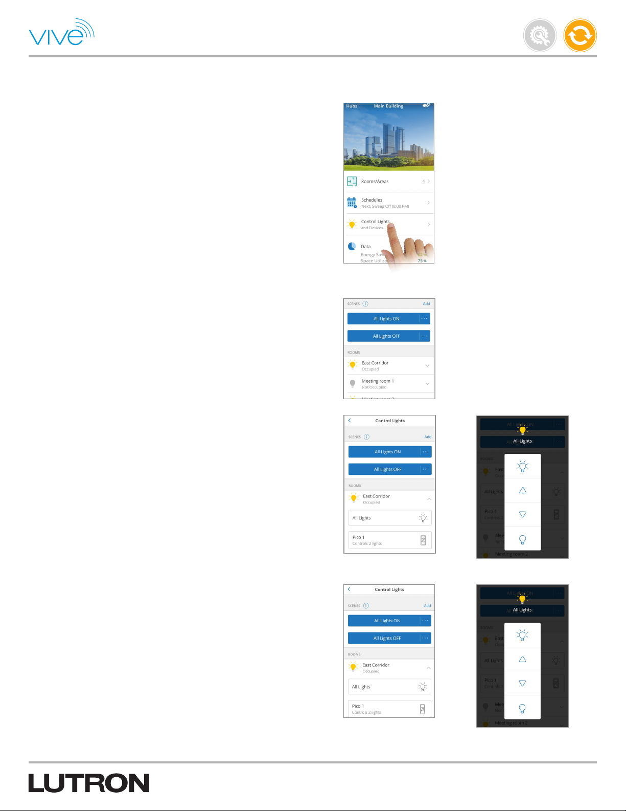
Control Lights & Devices
Tap the “Control Lights” menu on the main dashboard of the Vive
software. On the next screen you can do several things.
a. Control Scenes - Press the desired scene to manually activate
or deactivate.
Maintain
P/N 041571j
b. Control Lights - Control all lights in a desired room via the virtual
light control for an area.
c. Manually control specific lights by simulating button presses on
the programmed virtual Pico remote controls.
Continued on next page...
52
Page 53
Control and Monitor (continued)
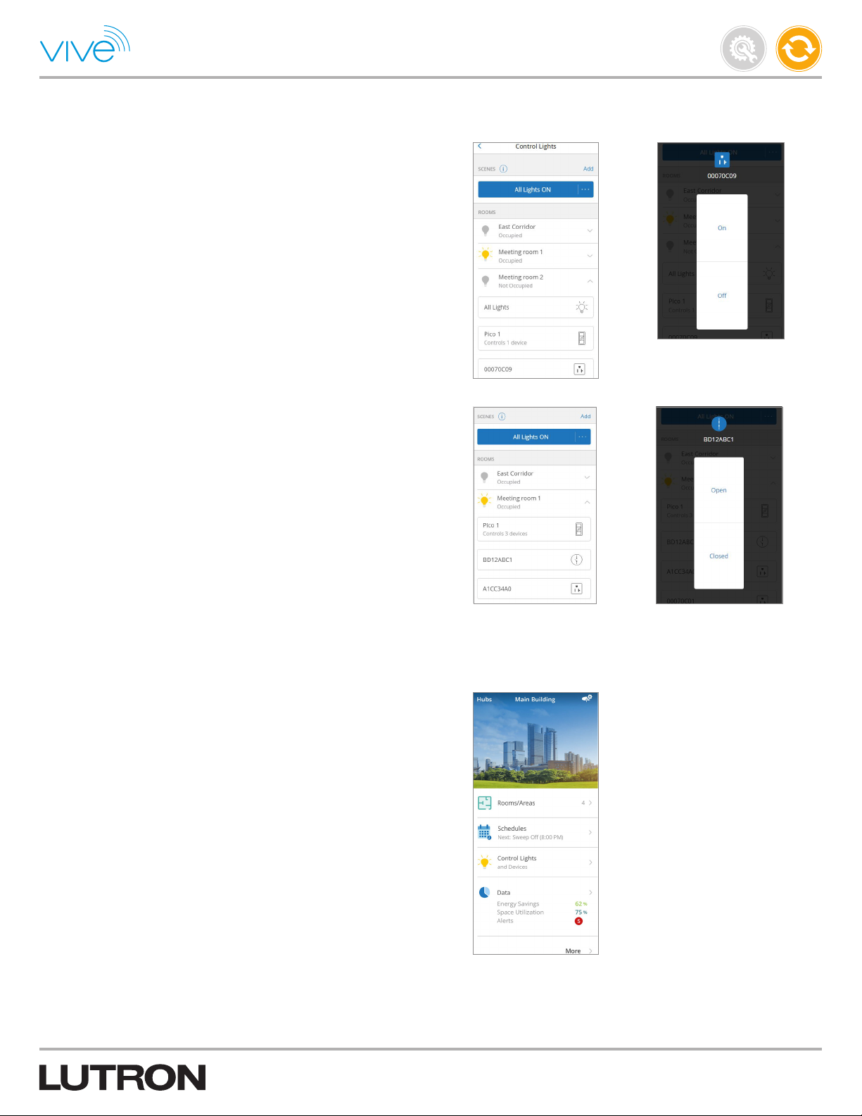
Control Lights & Devices (continue d)
d. Control Receptacles - Control individual receptacles via the virtual
control in a room.
e. Control CCO Modules - Control individual CCO modules via the
virtual control in a room.
Maintain
P/N 041571j
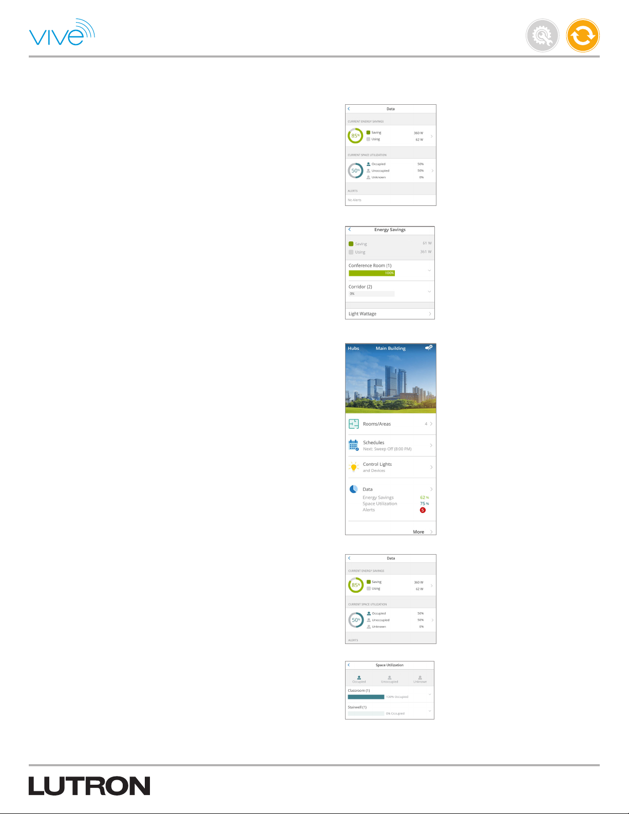
Current Energy Savings
Follow the steps below to monitor the current energy savings.
1. Tap the “Data” menu on the main dashboard of the Vive software
to monitor the current energy savings & space utilization for the hub.
Continued on next page...
53
Page 54
Control and Monitor (continued)
Current Energy Savings (continued)
2. Tap “Current Energy Savings” to view current energy savings per
room type.
3. Expand a room type row to view current energy savings for
individual rooms.
This is more accurate if fixture wattage is entered into the system for
each device. A warning will display if wattage information has not
been entered for some of the fixtures. Enter the wattage of fixtures
by tapping “Light Wattage” on the energy savings screen.
Maintain
P/N 041571j
Current Space Utilization
Current Space Utilization displays run-time occupancy status of
different rooms. Follow the steps below to monitor the current
space utilization.
1. Tap the “Data” menu on the main dashboard of the Vive software to
monitor the current space utilization for the hub.
2. Tap “Current Space Utilization” to view current space utilization per
room type.
3. Expand a room type row to view current occupancy information for
the individual rooms.
Unknown status covers rooms for whom status is not available
(e.g., sensors are not responsive because of low battery etc.).
54
Page 55
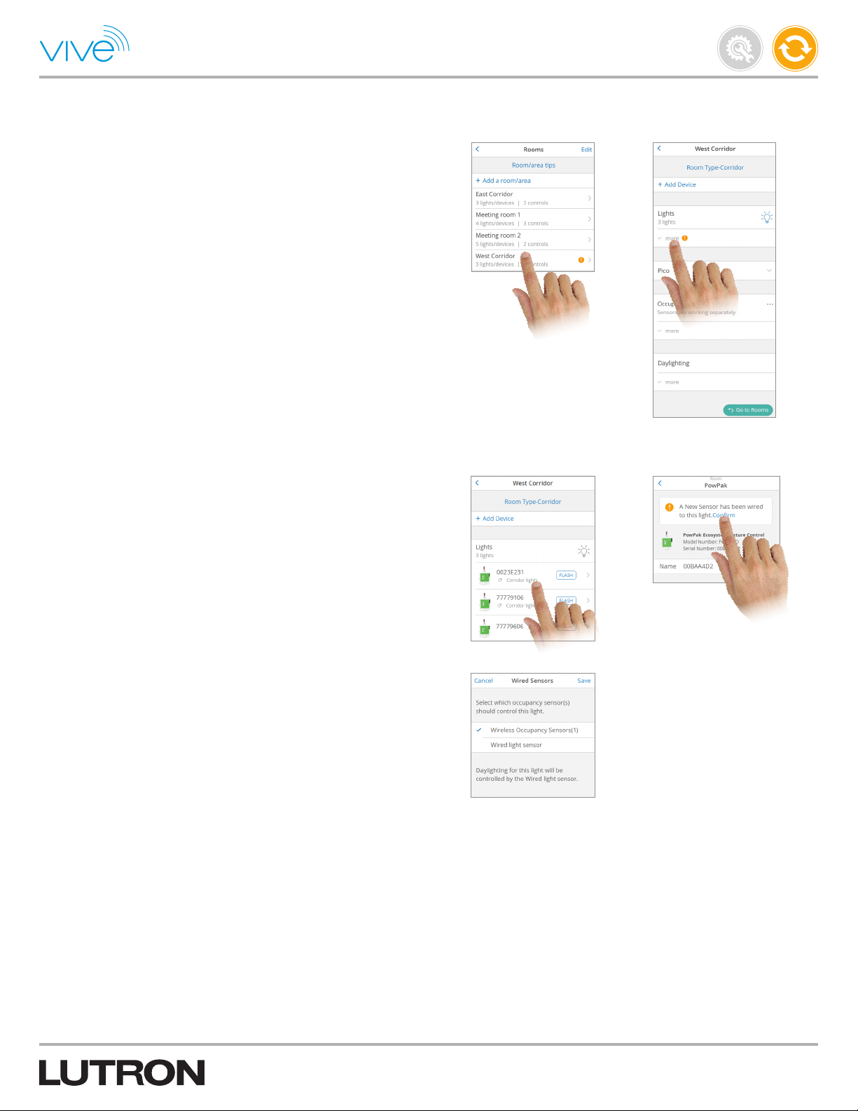
Runtime Status
Fixture Sensor Gets Connected
If a fixture sensor is connected to a device that is already added to a
hub, you will see a notification in the software.
To add this newly connected fixture sensor to the hub:
1. From the “Rooms” list screen, tap the area row and then
expand “Lights”.
Maintain
P/N 041571j
2. Select the device that is attached to the new fixture sensor.
Tap“Confirm” to add this sensor.
3. If the device is assigned to a Radio Powr Savr sensor, you will be
asked to pick which sensor (wireless or wired) should control this
device. Select the appropriate option.
Continued on next page...
55
Page 56
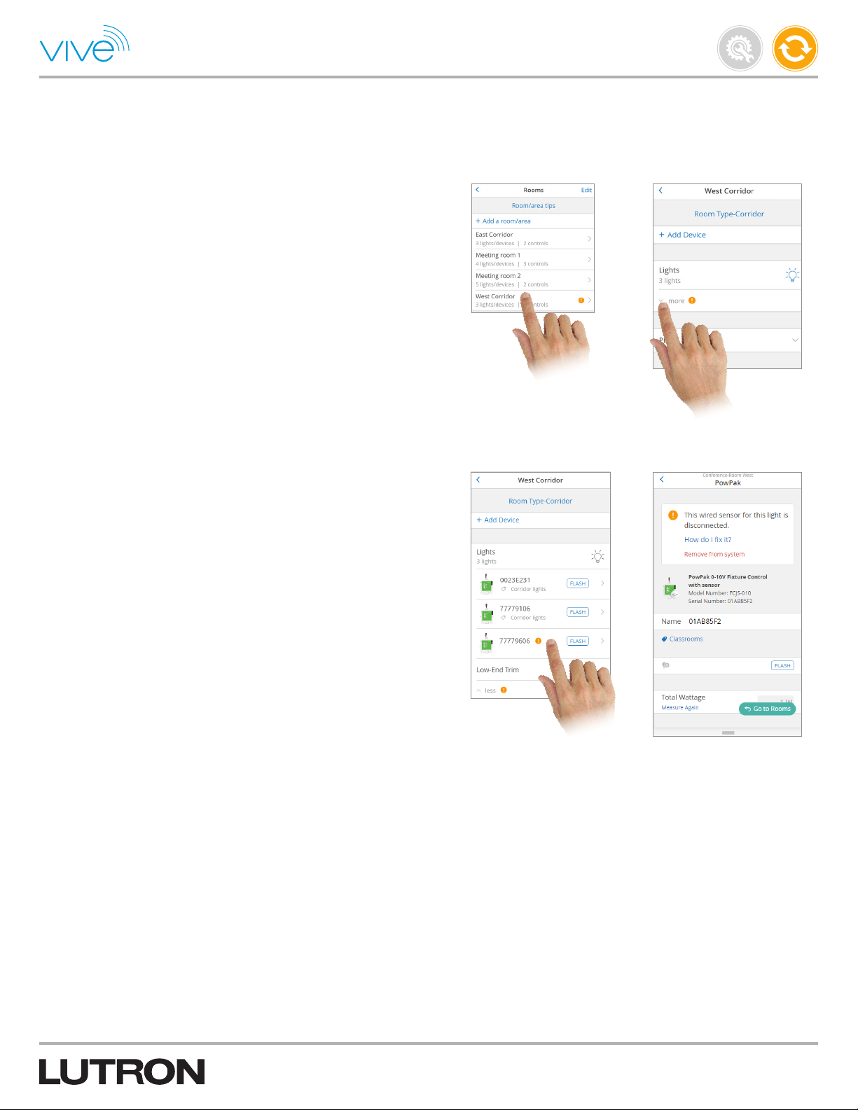
Runtime Status (continued)
Fixture Sensor Gets Connected (continued)
If a fixture sensor gets disconnected from a device that is added to a
hub, you will see a notification in the software.
To remove this fixture sensor from the hub:
1. From the “Rooms” list screen, tap the area row and then
expand “Lights”.
Maintain
P/N 041571j
2. Select the device that had the fixture sensor disconnected.
Tap “Remove from system” to remove the fixture sensor.
Note: If this fixture sensor is the only sensor in an occupancy group,
you will be notified that the occupancy group will be deleted.
Note: If you did not intentionally disconnect the fixture sensor or if
you see the fixture sensor connection / disconnection notification
frequently, verify that the fixture sensor is properly wired to the
device.
56
Page 57
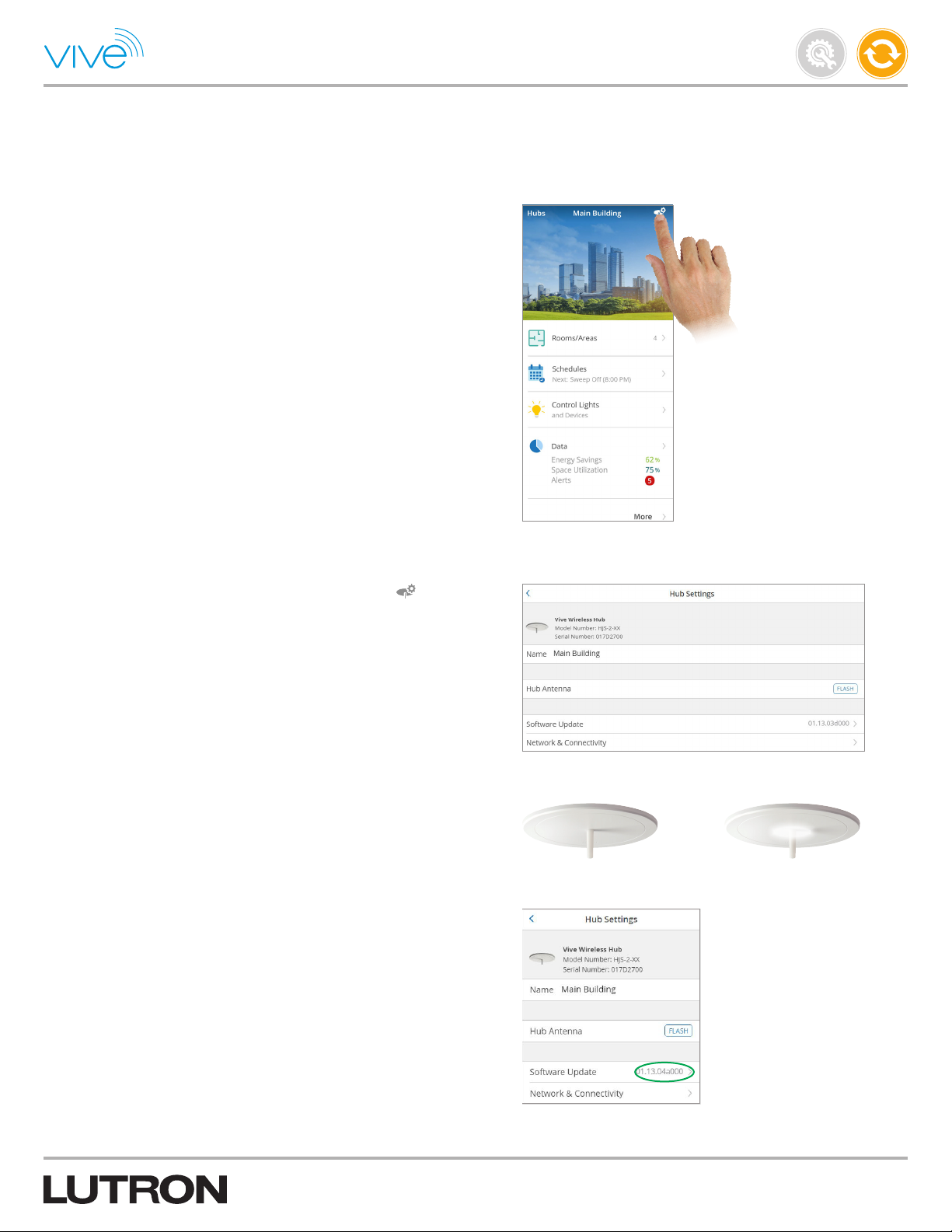
Configure the Hub
Firmware Update
Follow these steps to complete a firmware update.
1. Connect to the hub via a Wi-Fi network or Ethernet.
Note: It can take up to 1 minute to connect to a laptop or desktop
the first time. To speed up the connection, disconnect from any VPN
before proceeding.
Maintain
P/N 041571j
2. From the main dashboard in the Vive software, click and then
click “Software Update”.
3. During the update process, the antenna on the hub will blink
blue and white alternately. The process will take approximately
10minutes. The hub will reboot after the update is complete.
4. Navigate to “Hub Settings” screen again and verify the new software
version of the hub.
Continued on next page...
57
Page 58

Configure the Hub (continued)
Ethernet Settings
By default, the Ethernet is set up to use DHCP. As a result, the hub
will be expecting a DHCP server on the network to assign it an IP
address. Usually, an IT department will want to assign IP addresses
to the devices on the network. In this case, you will have to set a
static IP address on the hub. Follow the steps below.
1. Connect an Ethernet cable between the hub and a laptop or
desktop computer.
2. Connect the smart device to the Wi-Fi network of the hub.
Maintain
P/N 041571j
3. From the main dashboard in the Vive software, tap and then tap
“Network & Connectivity”.
4. Tap “Ethernet” and modify the Ethernet settings as needed. To set a
static IP address, use the “DHCP” slider to disable DHCP. Enter the
settings provided to you by your IT department. If no settings were
supplied, use the following:
a. IP Address: 192.168.4.1
c. Gateway: 0.0.0.0
b. Subnet Mask: 255.255.255.0
d. DNS Server 1: 8.8.8.8
Continued on next page...
58
Page 59

Configure the Hub (continued)
Ethernet Settings (continued)
5. Disconnect from the Wi-Fi network and type the IP address of
the hub (e.g., http://192.168.4.1) into a web browser on a laptop
or desktop computer. The first time you do this, you will get a
warning saying that the connection is not safe / private. There is no
security concern because the hub uses a self-signed certificate. Tap
“Proceed to the website” and enter the hub password.
Note: If the hub password is entered incorrectly 10 times in a row,
the hub will lock. To unlock the hub, either wait 1 hour or cycle
power to the hub.
Note: When connecting to the hub via Ethernet, type the IPaddress
of the hub into the web browser (vive.lutron.com will not work). If the
IT department has set up a DNS server, you may be able to type in a
more descriptive name instead of the IP address.
Note: If you want to turn off the Wi-Fi network or hide the SSID
broadcast, proceed to the Wi-Fi Settings section.
Maintain
P/N 041571j
6. From the main dashboard in the Vive software, tap “Hubs” to
access the different hubs. If multiple hubs are connected to the
same network and Ethernet is enabled and configured on all hubs,
you will be able to access the Vive software on all of the hubs when
connected to the wired network.
Wi-Fi Settings
After initial setup of the hub, it may be necessary to change the
Wi-Fi name or password, hide the SSID broadcast, or disable Wi-Fi.
Follow the steps below to change the Wi-Fi settings.
1. From the main dashboard in the Vive software, tap and then tap
“Network & Connectivity”.
2. Tap “Vive Wi-Fi” and modify the desired items appropriately.
Note: The default Wi-Fi IP address of the hub is 192.168.3.1
Note: Before disabling Wi-Fi on a hub, you must set up a hub
password so that you can access the hub through the wired
Ethernet. Failure to do so will require you to reset the Wi-Fi settings.
See Reset Passwords and Settings section if you need to reset
the Wi-Fi settings.
Continued on next page...
59
Page 60

Configure the Hub (continued)
Time & Date / Location
Time, date, and location settings are primarily used to determine the
sunrise and sunset times for astronomic timeclock events.
If you have allowed the Vive software to access your location, when
a new hub is added, the location and time will be automatically
selected and saved to the hub.
If you haven’t allowed location access, the location will not be set
and you will have to enter the location manually.
Follow the instructions below to modify or enter the location
manually.
1. From the main dashboard in the Vive software, tap .
Maintain
P/N 041571j
2. Tap “Advanced” and then select “Location & Time” to view or modify
the hub location, date & time.
Accessing Other Hubs on the Wired Network
You can access other hubs via the building Wi-Fi / wired network or
by connecting directly to the network via Ethernet using a laptop or
desktop computer.
1. Connect the hubs by wiring them together via Ethernet. This allows
you to easily access them without connecting to each hub Wi-Fi
network. Up to 64hubs can be connected.
2. Configure each hub for wired access by connecting it to the
Ethernet network and setting up the Ethernet connection (see
Ethernet Settings section).
3. Connect to the building Wi-Fi network and navigate to the hub using
the IP address or name set by the IT department.
Continued on next page...
Building
Building Wi-Fi
network
Hub Hub
Maximum 330 ft (100 m) each
Link segment
Management
System (BMS)
60
Page 61

Configure the Hub (continued)
Hub Support File
The hub support file is used for troubleshooting and contains
information about the programmed devices and the hub settings.
1. From the main dashboard in the Vive software, tap .
2. Tap “Help”.
Maintain
P/N 041571j
3. Tap “Generate Support File”.
a. If using a laptop, desktop, or AndroidT device, save the file to the
desired location and e-mail to systemsupport@lutron.com
b. If using an iPhone mobile device, tap “ ” to share the file
via e-mail. Select the desired mail application and e-mail to
systemsupport@lutron.com
Continued on next page...
61
Page 62

Configure the Hub (continued)
Reset Passwords and Settings
In the event that the Wi-Fi or hub password is lost or forgotten, both
passwords can be reset without restoring the hub to factory default.
Follow the steps below to clear the hub password and reset the
Wi-Fi settings.
1. Press and hold the button on the back of the hub for 30 seconds
until the antenna on the hub starts to blink rapidly.
2. The hub will go in access recovery mode for 30 minutes. The Wi-Fi
name will change to “Vive Access Recovery xxxxxx” and password
protection will be removed.
Maintain
P/N 041571j
3. Connect to the Wi-Fi network of the hub and follow the instructions
to reset hub access details.
4. Reconnect to the hub using the new password.
62
Page 63

Security Log
You can generate a log of key security events in the system.
1. From the main dashboard in the Vive software, tap and then tap
“Advanced”.
2. Click “Generate Security Log” to generate and download the log to
your device.
Maintain
P/N 041571j
63
Page 64
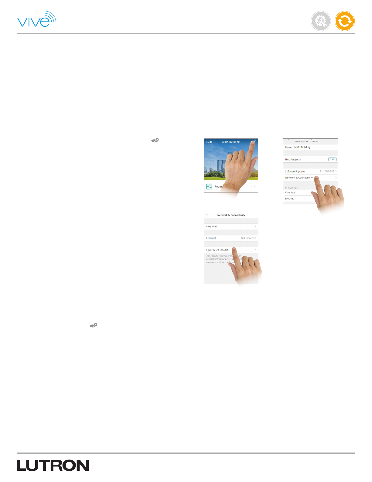
Security Certificates
The Vive hub uses its default security certificates; however, you can
install your own custom security certificate on a Vive hub to enable
browsers to identify the hub during secure access (HTTPS).
Note: Please use a laptop or desktop computer to install a
certificate. The certificate and private key must be imported in PEM
format. The secure certificate private key should be between
RSA 2048 – RSA 4096.
Follow the steps below to update or install a new security
cer tificates:
1. From the main dashboard in the Vive software, tap and then tap
“Network & Connectivity”.
Maintain
P/N 041571j
2. Click “Security Certificates” and follow the instructions to install the
certificate.
Note: Tap on “What is a security certificate?” to know more details
about security certificates.
3. Verify the installation by opening a new browser window and
reconnecting to the hub using an HTTPS connection over Ethernet.
Note: If the certificate is invalid then you will not be able to connect
to the hub. You can recover access to the hub by following
instructions:
a. Connect to the hub’s Wi-Fi and access Vive to bypass the failed
connection.
b. Navigate to Hub settings and then tap “Advanced”.
c. Click “Security Certificate” and then uninstall the invalid certificate
and install a new certificate.
If you do not have access to the hub’s Wi-Fi, then follow following
steps:
a. Press and hold the black button on the back of your hub for
30 seconds until the antenna on the hub starts to blink rapidly.
b. The hub will go into access recovery mode and become open for
reconnection. The hub password will clear and the Wi-Fi name will
change to “Vive Access Recovery xxxxxxxx”.
c. Connect to the hub’s Wi-Fi and follow the instructions to set a new
Wi-Fi name and password.
64
Page 65
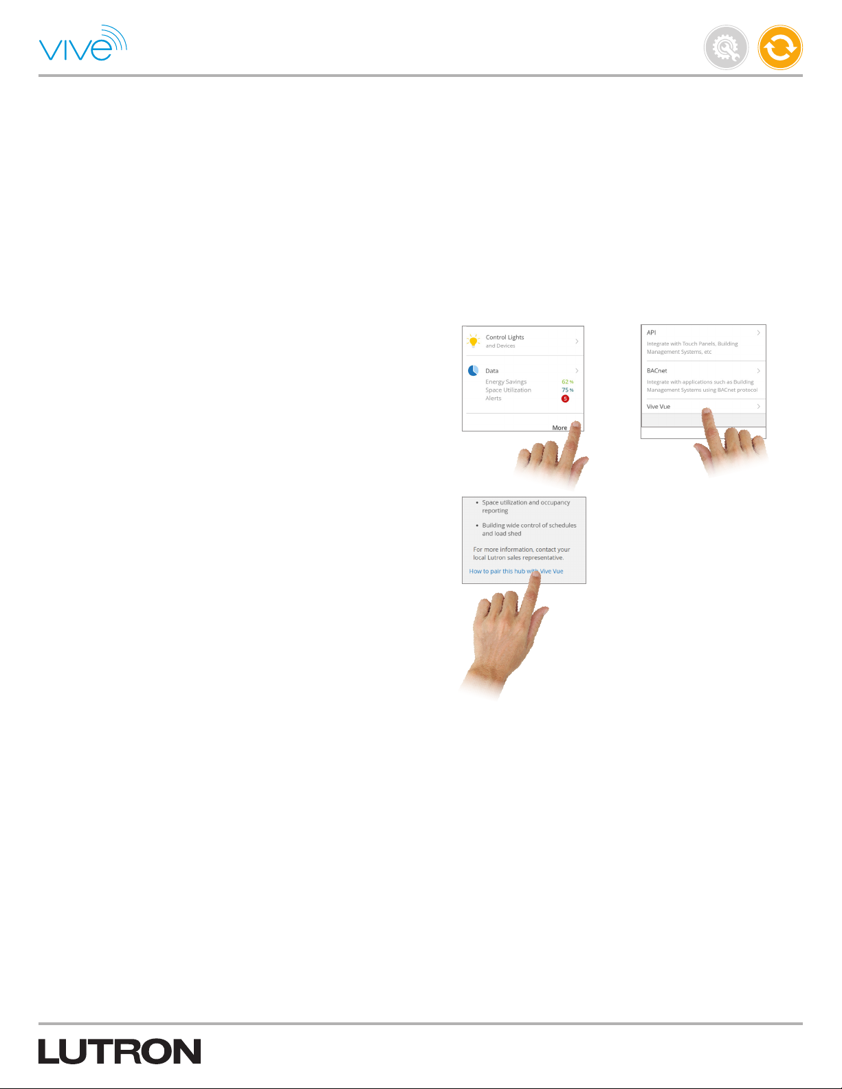
Vive Vue
Vive Vue is a server installed locally at your premises to centrally
manage multiple hubs, it works as a single dashboard for all your
hubs. It provides:
1. Graphical floorplan view for control and navigation
2. Centralized energy logging & historical reports
3. Space utilization and occupancy reporting
4. Building-wide control of schedules and load shed
Follow the steps below to view Vive Vue details:
1. From the main dashboard in the Vive software, tap “More” and then
tap “Vive Vue”.
Maintain
P/N 041571j
2. To pair a hub with a Vive Vue server, please select “How to pair this
hub with Vive Vue” link.
3. Check the hub readiness report to make sure that the hub is ready
to be paired.
4. To setup the Vive Vue server, contact Lutron to schedule a field
service engineer.
Once a hub is paired with the Vive Vue server you can manage
its load shed and events using a Vive Vue server dashboard. You
can also see occupancy and energy reports on the dashboard. If
required, a Hub can be unpaired later from Vive Vue server.
65
Page 66

Visit www.lutron.com/vive for a wide range of tutorials, videos, FAQs, and forums.
P/N 041571j
Lutron, Pico, PowPak, Vive, , Radio Powr Savr, and Maestro are trademarks or registered trademarks of Lutron Electronics Co., Inc. in the US and/or
other countries.
Safari, iPhone, and App Store are trademarks of Apple Inc., registered in the U.S. and other countries.
All other product names, logos, and brands are property of their respective owners.
Lutron Contact Numbers
WORLD HEADQUARTERS
U.S.A.
Lutron Electronics Co., Inc.
7200 Suter Road
Coopersburg, PA 18036-1299
TEL: +1.610.282.3800
FAX: +1.610.282.1243
support@lutron.com
www.lutron.com/support
North & South America
Customer Assistance
U.S.A., Canada, Caribbean:
1.844.LUTRON1 (1.844.588.7661)
Mexico:
+1.888.235.2910
Central/South America:
+1.610.282.6701
UK AND EUROPE:
Lutron EA Limited
125 Finsbury Pavement
4th floor, London EC2A 1NQ
United Kingdom
TEL: +44.(0)20.7702.0657
FAX: +44.(0)20.7480.6899
FREEPHONE (UK): 0800.282.107
Technical Support: +44.(0)20.7680.4481
lutronlondon@lutron.com
ASIA:
Lutron GL Ltd.
390 Havelock Road
#07-04 King’s Centre
Singapore 169662
TEL: +65.6220.4666
FAX: +65.6220.4333
Technical Support: 800.120.4491
lutronsea@lutron.com
Asia Technical Hotlines
Northern China: 10.800.712.1536
Southern China: 10.800.120.1536
Hong Kong: 800.901.849
Indonesia: 001.803.011.3994
Japan: +81.3.5575.8411
Macau: 0800.401
Taiwan: 00.801.137.737
Thailand: 001.800.120.665853
Other Countries: +65.6220.4666
P/N 041571 Rev. J
03/2021
 Loading...