

Page 1

®
Vive PowPak Relay Module with Softswitch Wireless Lighting Control
1
369908h 1 06.08.20
Vive PowPak Relay Module with Softswitch
The PowPak Relay Module with Softswitch is a radio-frequency
(RF) device that uses Lutron patented Softswitch technology to
control general-purpose loads based on input from Pico remote
controls and Radio Powr Savr occupancy and daylight sensors.
An optional, low-voltage dry contact closure output (CCO) is
available to communicate occupancy status to 3rd-party
systems such as HVAC controllers.
Communication with RF input devices, such as Pico remote
controls and Radio Powr Savr sensors, is accomplished using
Lutron Clear Connect RF Technology.
These products are also compatible with the Vive hub which
enables a simple setup process using a standard web browser
on any Wi-Fi enabled phone, tablet or computer. It also enables
control and monitoring of all Vive devices. The Vive hub can be
added at any time. System reprogramming will be required. For
a complete list of features supported with the Vive hub, see
specification submittal 369902 at www.lutron.com
Note for Replacement: RMJS / URMJS - the “S” model can
replace the non-”S” model.
RMJS-16RCCO1DV-B model shown
Features
• Softswitch: Lutron patented technology prevents arcing of relay
contacts, extending product lifetime
• Various operating voltages available—refer to model number
chart on next page for details on voltage requirements
• Capable of switching general-purpose loads
• New model available for use with emergency lighting
1
• Optional low-voltage dry contact closure output provides
integration to building management systems, HVAC, VAV, etc.
• Receives wireless inputs from up to 10 Pico remote controls,
10 Radio Powr Savr occupancy / vacancy sensors, and
1 Radio Powr Savr daylight sensor
• Utilizes Lutron Clear Connect RF Technology—refer to model
number chart on next page for frequency band data
• Mounts to the exterior of a U.S. style junction box through a
standard size knockout
1
For systems with backup emergency generators only.
SPECIFICATION SUBMITTAL Page
Job Name:
Job Number:
Model Numbers:
Page 2

®
Vive PowPak Relay Module with Softswitch Wireless Lighting Control
2
Model Numbers
369908h 2 06.08.20
Description Model Number Region Operating
Voltage
PowPak Relay
Module with
Softswitch
RMJS-16R-DV-B U.S.A., Canada, Mexico 120/277 V~
Israel, Hong Kong 220–240 V~
RMJS-5R-DV-B U.S.A., Canada, Mexico 120/277 V~
Israel, Hong Kong 220–240 V~
URMJS-16R-DVB U.S.A. (BAA Compliant) 120/277 V~
RMJS-16R-DV-B-EM U.S.A., Canada, Mexico 120/277 V~
PowPak Relay
Module with
Softswitch and
Occupancy-Status
CCO
RMJS-16RCCO1DV-B U.S.A., Canada, Mexico 120/277 V~
Israel, Hong Kong 220–240 V~
RMJS-5RCCO1-DV-B U.S.A., Canada, Mexico 120/277 V~
Israel, Hong Kong 220–240 V~
URMJS-16RCCO1DVB U.S.A. (BAA Compliant) 120/277 V~ 431.0 –437.0 M Hz
NOTE: Contact Lutron for frequency band compatibility for your geographic region if it is not indicated above.
Frequency Band
431.0 –437.0 M Hz
433.05–434.79 MHz
431.0 –437.0 M Hz
433.05–434.79 MHz
431.0 –437.0 M Hz
431.0 –437.0 M Hz
431.0 –437.0 M Hz
433.05–434.79 MHz
431.0 –437.0 M Hz
433.05–434.79 MHz
SPECIFICATION SUBMITTAL Page
Job Name:
Job Number:
Model Numbers:
Page 3

®
Vive PowPak Relay Module with Softswitch Wireless Lighting Control
3
Specifications
Regulatory Approvals
• UL® Listed (U.S.A.)
• UL 924 Listed (RMJS-16R-DV-B-EM only)
• FCC approved. Complies with the limits for a Class B
device, pursuant to Part 15 of the FCC rules. (U.S.A.)
• Complies with requirements for use in other spaces
used for environmental air (plenums) per
NEC® 2014 300.22(C)(3)
• Classified in accordance with CAN / ULC-S142
as discrete product certified for installation in an
air-handling space.
• CSA or cUL and IC (Canada) (RMJS- only)
• COFETEL (Mexico) (RMJS- only)
• NOM (Mexico) (RMJS- only)
Power
• Operating voltage: 120 / 277 V~ 50 / 60 Hz
• Standby Power Consumption (all models): < 1.0 W
System Communication
• Operates using Clear Connect RF Technology for reliable
wireless communication; refer to model number chart on
page 2 for band frequency details
• RF range is 30 ft (9 m)
• Wireless sensors and controls must be located within
60ft (18 m) line of sight, or 30 ft (9 m), through walls, of
the associated control module. The 60 ft (18 m) range is
not reduced by a ceiling tile obstruction.
• Contact Lutron first for applications using foil-backed or
metallic ceiling tiles.
Environment
• Ambient operating temperature: 32 °F to 131 °F
(0 °C to 55 °C)
• 0% to 90% humidity, non-condensing
• For indoor use only
• All drivers and ballasts used with Vive wireless controls
must comply with the limits for a Class A device
pursuant to Part 15 of the FCC Rules
369908h 3 06.08.20
Mounting
• This device can be installed on a junction box
or marshalling box using the conduit nut or with
mounting screws. The device must NOT be mounted
inside a metallic enclosure – only on the exterior of a
junction box, or marshalling box. Improper installation
can result in degraded wireless communications and
intermittent or sustained communications failures and
will not be covered under warranty. For applications
(in U.S.A.) where code requires the PowPak control to
be installed inside an additional junction box, please
see Lutron Application Note #423 (P/N 048423) at
www.lutron.com for how to perform this installation.
For all other installations, refer to the installation
instructions and consult local and national electric
codes for proper installation. The PowPak control
needs to be accessible for some programming steps.
Record where it is mounted of that it can be easily
located later.
Load
• -16R models: 16 A; -5R models: 5 A;
RMJS-16R models: No minimum load requirements.
• Load types include (but are not limited to):
Incandescent, MLV, ELV, Resistive, Inductive,
Magnetic fluorescent, Electronic fluorescent
• Motor rating:
RMJS-16R- and URMJS-16R- models:
1/2 HP (120 V~), 11⁄2 HP (277 V~)
RMJS-5R- and URMJS-5R- models: 1/6 HP (120 V~),
1/3 HP (277 V~)
Softswitch
• Patented Softswitch circuit eliminates relay arcing at
mechanical contacts
• Extends relay life to an average of 1 million cycles
• Output is non-latching
Key Design Features
• LED status indicator shows current load status and
provides programming feedback
• Power failure memory: If power is interrupted, connected
loads will return to the previous level prior to interruption
SPECIFICATION SUBMITTAL Page
Job Name:
Job Number:
Model Numbers:
(continued on next page . . .)
Page 4

®
Vive PowPak Relay Module with Softswitch Wireless Lighting Control
Switching
Voltage
0-24 V-
0-24 V~
Resistive
Load
1.0 A
0.5 A
R
4
369908h 4 06.08.20
Specifications (continued)
Contact Closure Output (CCO version only)
Emergency Model Sequence of Operation
With a Vive hub:
• Normal mode: The RMJS-16R-DV-B-EM can switch
loads as normal and respond to local button presses,
Pico wireless controls, and occupancy / daylight sensors.
• If the emergency PowPak loses power for greater than
250 mS, it will automatically go into emergency mode
(full output, relay closed), when emergency power is
restored to the PowPak, for as long as the Vive hub
has no power. All local buttons, Pico wireless controls
and occupancy / daylight sensors will not respond. The
emergency light level of the emergency PowPak can be
configured using the Vive hub.
• When normal power is restored to the Vive hub and
emergency PowPak, the emergency PowPak will return
to the previous light level in most cases within 3 minutes,
but guaranteed within 10 minutes of normal power being
restored. It will again accept local button control, input
from Pico wireless controls, and occupancy / daylight
sensors.
Without a Vive hub:
• Normal mode: The RMJS-16R-DV-B-EM can switch
loads as normal and respond to local button presses,
Pico wireless controls, and occupancy / daylight sensors.
• If the emergency PowPak loses power for greater than
250 mS, it will automatically go into emergency mode (full
output, relay closed) for 90 minutes, when emergency
power is restored to the PowPak. All local buttons, Pico
wireless controls and occupancy / daylight sensors will
not respond for 90 minutes.
• When normal power is restored, the emergency PowPak
will remain in emergency mode for 90 minutes (full
output, relay closed). It will then return to the previous
light level and accept local button control, inputs from
Pico wireless controls, and occupancy / daylight sensors.
• Provides occupancy status to 3rd-party equipment
such as building management systems, HVAC, and
VAV controllers
• Provides both normally open (NO) and normally
closed (NC) dry contacts
• Maintained output type
• CCO terminals accept
20 AWG to 16 AWG
(0.5 mm2 to 1.5 mm2)
solid or stranded wire
Switching
Voltage
0-24 V0-24 V~
Resistive
Load
R
1.0 A
0.5 A
• Output is latching
• Not for voltages greater than 24 V-
• The CCO is not rated to control unclamped, inductive
loads. Inductive loads include, but are not limited
to: relays, solenoids, and motors. To control these
types of equipment, a flyback diode must be used
(DC voltages only). See diagram below. For more
information, please see Application Note #434
(P/N 048434 at www.lutron.com).
Warranty
• 1 year limited warranty. The customer can register
Flyback
Diode
(required for
inductive
loads)
NO
CCO
Output
NC
COM
Inductive
Load
24 V-
max.
+
-
the product to increase the warranty period from
1 year to 5 years. Please visit www.lutron.com/
TechnicalDocumentLibrary/369-119_Wallbox_
Warranty.pdf for warranty details.
Job Name:
Job Number:
SPECIFICATION SUBMITTAL Page
Model Numbers:
Page 5

®
Vive PowPak Relay Module with Softswitch Wireless Lighting Control
5
369908h 5 06.08.20
Dimensions
Dimensions are shown as: in (mm)
3.94
(100)
3.42
(87)
1/2 in or 21 mm trade size
knockout opening
Range Diagrams
PowPak
Relay Module
Install in center of room to
maximize RF coverage.
Radio Powr Savr
Occupancy Sensor
30 ft (9 m)
Maximum
Pico
Remote
Control
40 ft (12 m)
2.82
(72)
Test
1.25
(32)
30 ft (9 m)
• Contact Lutron first for applications using foil-backed or metallic ceiling tiles.
NOTE: Wireless sensors and controls must be located within 60 ft (18 m) line of sight, or 30 ft (9 m), through walls, of the
associated control module. The 60 ft (18 m) range is not reduced by a ceiling tile obstruction.
SPECIFICATION SUBMITTAL Page
Job Name:
Job Number:
Model Numbers:
Page 6

®
Vive PowPak Relay Module with Softswitch Wireless Lighting Control
6
369908h 6 06.08.20
System Diagram
To power source
and load
Pico Remote Control (up to 10)
To 3rd-Party
Radio Powr Savr Occupancy Sensor (up to 10)
Radio Powr Savr Daylight Sensor (up to 1)
Equipment
Note: CCO models only
Default Operation
Transmitting Device Transmitted Command Softswitch
Pico
Remote Control
Radio Powr Savr
Occupancy Sensor
Radio Powr Savr
Vacancy Sensor
Radio Powr Savr
Daylight Sensor
NOTES:
1
CCO models only.
On Close No Action
Off Open No Action
Raise Close No Action
Lower No Action No Action
Preset Close No Action
Occupied Close NO = Close, NC = Open
Unoccupied Open NO = Open, NC = Close
Occupied No Action NO = Close, NC = Open
Unoccupied Open NO = Open, NC = Close
Ambient Light Below
Close No Action
Target Level
Ambient Light Above
Open No Action
Target Level
Relay Default Action
CCO Default Action
1
SPECIFICATION SUBMITTAL Page
Job Name:
Job Number:
Model Numbers:
Page 7

®
Vive PowPak Relay Module with Softswitch Wireless Lighting Control
7
369908h 7 06.08.20
Wiring Diagram (RMJS- and URMJS- models)
Line / Hot (L)
Neutral (N)
Junction Box*
NC
NO
COM
Switched Line / Hot
To
third-party
equipment
Load
* NOTE: The control module mounts to the exterior of a U.S.-style junction box.
SPECIFICATION SUBMITTAL Page
Job Name:
Model Numbers:
Job Number:
Page 8
®
Vive PowPak Relay Module with Softswitch Wireless Lighting Control
8
369908h 8 06.08.20
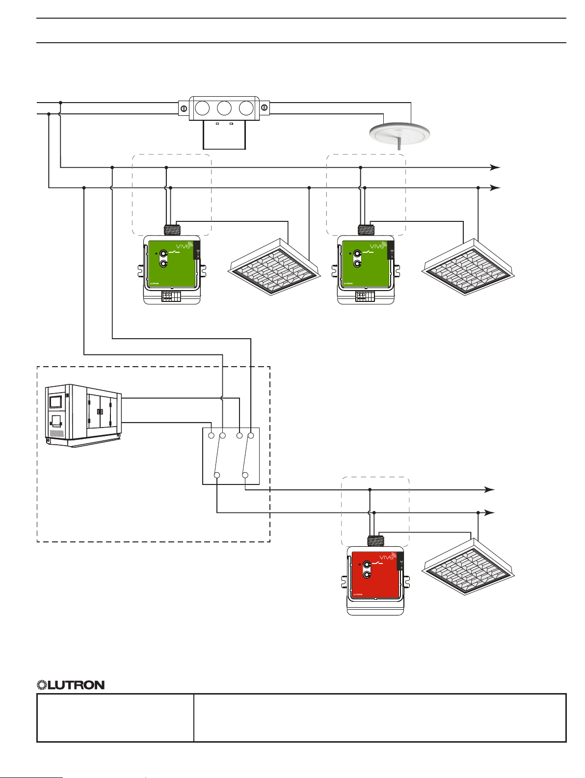
System Wiring Diagram (Vive Hub with Emergency PowPak)
120 / 277 V~ Normal Feed
Neutral (N)
Line / Hot (L)
Neutral (N)
120 / 277 V~ Normal Feed
Neutral (N)
24 VCommon
Junction Box Junction Box
Switched Line / Hot
PowPak
120 / 277 V~
ADV
lutron.com
Normal Load
RMJS-16R-DV-B
(Normal)
120 / 277 V~ Generator /
Emergency Feed
Neutral (N)
Switched Line / Hot
PowPak
120 / 277 V~
ADV
lutron.com
RMJS-16R-DV-B
Normal Load
(Normal)
NOTE: Solution is not applicable for an
*
Uninterruptable Power Supply (UPS)
backup system. RMJS-16R-DV-B-EM
must see a complete change-over of
power from normal to emergency for
the unit to go into emergency mode.
To additional
RMJS-16R-DV-B
PowPak units
Emergency
Backup Generator *
Automatic
Transfer
Switch
120 / 277 V~
Emergency Feed
Junction Box
Neutral (N)
Switched Line / Hot
Not Provided by Lutron
PowPak
120 / 277 V~
ADV
lutron.com
Normal Emergency
Load
RMJS-16R-DV-B-EM
(Emergency)
The Lutron logo, Lutron, Pico, PowPak, Softswitch, Vive, Radio Powr Savr, and Clear Connect are trademarks or registered trademarks of
Lutron Electronics Co., Inc. in the US and/or other countries.
SPECIFICATION SUBMITTAL Page
Job Name:
Model Numbers:
To additional
RMJS-16R-DV-B-EM
PowPak units
Job Number:
 Loading...