

Page 1
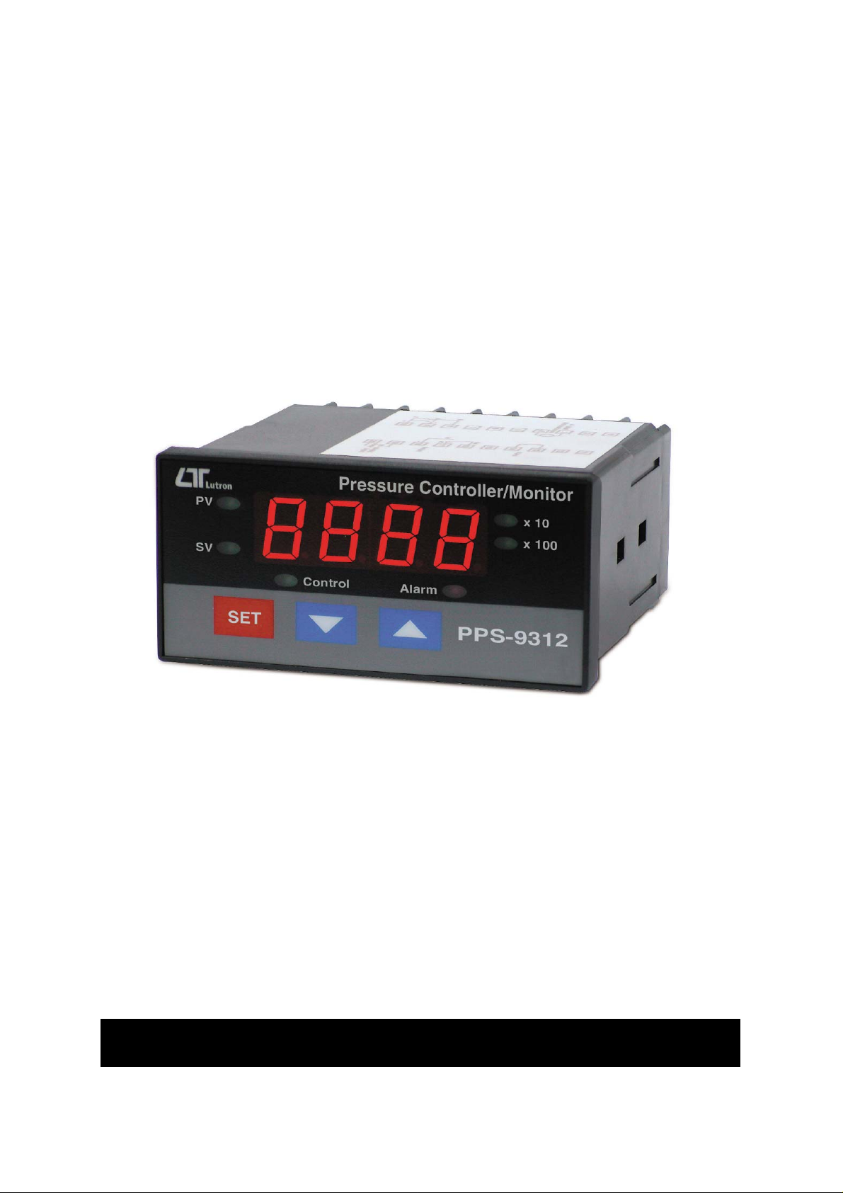
PRESSURE
Y
CONTROLLER/MONITOR
Model : PPS-9312
our purchase of this PRESSURE
CONTROLLER/MONITOR marks a step forward for you
into the field of precision measurement. Although this
PRESSURE controller is a complex and delicate instrument,
its durable structure developed. Please read the following
instructions carefully and always keep this manual within
easy reach.
OPERATION MANUAL
Page 2
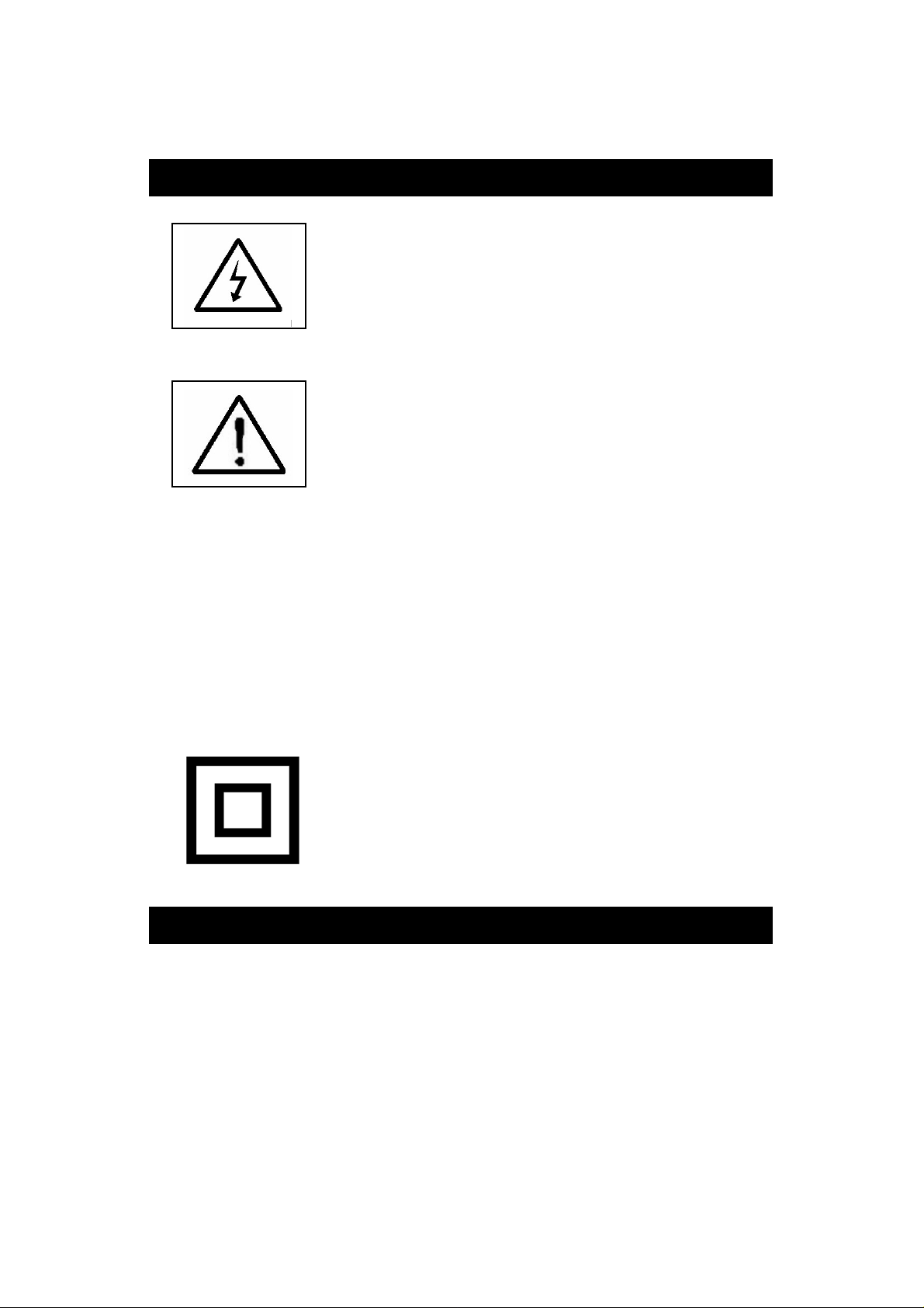
Caution Symbol
current > 0.5 Amp.
Caution :
* Risk of electric shock !
Caution :
* Do not use fingers or any tool
to touch the Wire Terminals.
* Do not apply the relay contact load
* The instrument contains no user
serviceable parts and should not
be opened by the user.
* Repair or after service should be
done by a qualified technician only.
* Power supply should apply the
correct ACV power voltage
* Cleaning - Only use the dry cloth to
clean the plastic case !
* Equipment protected throughout
by Double Insulation or Reinforced
Insulation.
Environmental Condition
* Comply with EN61010.
Transient over voltage at Mains Supply 2500V.
* Pollution Degree 2.
* Altitude up to 2000 meters.
* Indoor use.
* Relative humidity 80% max.
Page 3

TABLE OF CONTENTS
.
.
.
.
1.FEATURES..................................................................1
2.SPECIFICATIONS........................................................ 2
3. FRONT PANEL DESCRIPTION.......................................5
3-1 Display................................................................. 5
3-2 PV ( process value ) indicator.................................5
3-3 SV ( set value ) indicator.......................................
3-4 Set Button............................................................ 5
3-5 Button.............................................................
▼ 5
3-6 Button.............................................................▲ 5
3-7 Control relay indicator........................................... 5
3-8 Alarm relay indicator............................................ 5
3-9 X10 indicator........................................................ 5
3-10 X100 indicator................................................... 5
3-11 Wire terminals.................................................... 5
3-12 Case holder ....................................................... 5
3-13 RS232 terminal................................................... 5
5
4.MEASURING PROCEDURE............................................6
4-1 Terminal connection..............................................6
4-2 Pressure measurement..........................................6
4-3 1st layer setting procedures...................................7
4-4 2nd layer setting procedures..................................9
5. RS232 PC SERIAL INTERFACE.....................................
6. SYSTEM RESET..........................................................
7. OPTIONAL PRESSURE SENSORS
( Optional 2 wires pressure transmitters ) ....................16
8.THE ADDRESS OF AFTER SERVICE CENTER..................17
14
16
Page 4

1. FEATURES
* Meter connects with 2, 5, 10, 20, 50, 100, 200, 400 bar
sensor, no calibration procedures are necessary typically
when change a new sensor .
* Unit select : Bar, PSI, Kg/cm^2, inch Hg, mm Hg,
inch H2O, meter H2O, Atmosphere, hPa, KPa.
* Large red LED display, high brightness and easy to read.
* Control setting, Hi/Lo alarm setting.
* Control relay output, alarm relay output.
* Alarm Relay will make action when the reading value
reach to high/low alarm value.
* Control Relay will make action when the reading value
reach to control value.
* Hysteresis value setting for control and alarm function.
* Microprocessor circuit ensures high accuracy and
provides special functions and features.
* Power : 90 ACV to 260 ACV, 50/60 Hz.
* Cooperate the 4-20 mA pressure input, sensor can
install in the faraway position.
* DC 24V output, used for the power of pressure sensor.
* RS-232/USB computer interface.
* DIN size : 96 x 48 mm. Depth : 110 mm.
* Optional pressure sensor, TR-PS2W-xxBAR, PS93MA-xxBAR.
* Optional USB cable, USB-01.
* Optional data acquisition software.
* Optional GSM controller.
1
Page 5
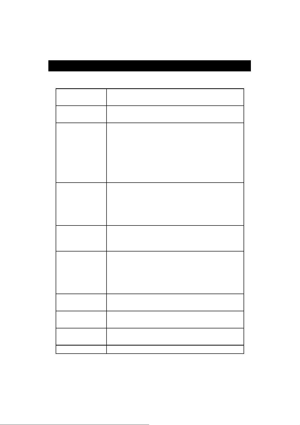
2. SPECIFICATIONS
2-1 General Specifications
Display 4 digits red LED, digit size : 14 mm.
x 10, x100 indicator
Circuit Custom chip of microprocessor LSI
circuit.
Sensor type Can cooperate with optional 2, 5, 10, 20,
50, 100, 200, 400 bar two wires 4 to 20
mA pressure sensor, new calibration are
not necessary typically when change the
new sensor .
* Sensor type can make the internal
setting with default
Display units Bar, Psi, Kg/cm^2, mm Hg, inch Hg,
meter H2O, inch H2O, Atmosphere,
hPa, KPa.
* Unit can make the internal setting with
default
Accuracy ± ( 0.5% + 2 d )
* Meter only.
* Within 23 ± 5 ℃℃
Pressure Cooperate the optional two wires ( or
sensor four wires ) 4 to 20 mA pressure
* optional
Offset adjust It can make the internal Offset setting
Gain adjust It can make the internal Gain setting
Input signal
from sensor
Sampling Time Approx. 1 second.
sensors ( transmitters ).
* two wires sensor : TR-PS2W-xxBAR
* Four wires sensor : PS93MA-xxBAR
with default.
with default
* Input 4 mA = 0 pressure
* Input 20 mA = full scale pressure
2
Page 6
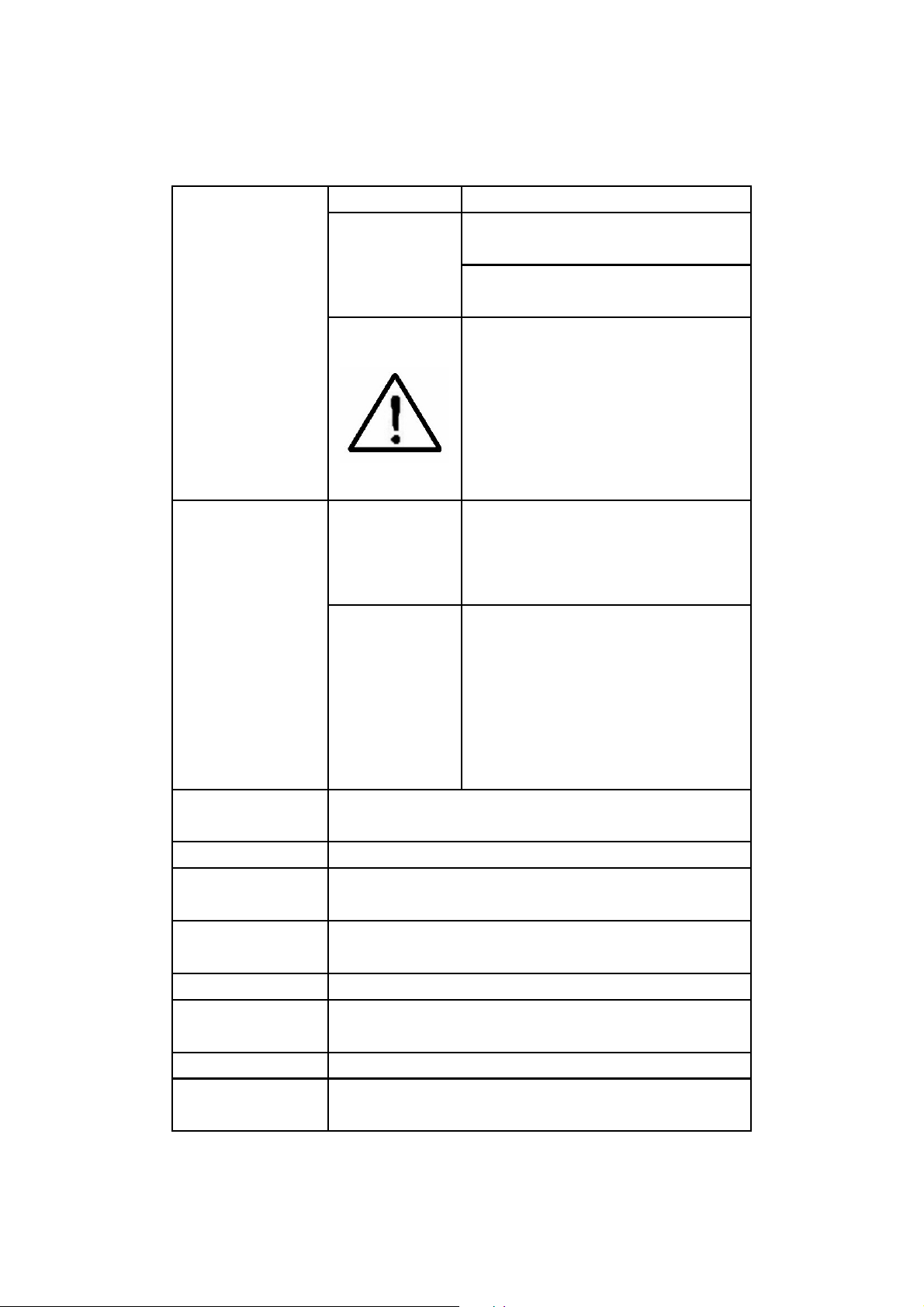
Relay Output Number 2 relays
*
y
e
permanently without
Function
Relay 1 :
Control relay.
Relay 2 :
High/Low alarm relay.
Max load 0.5 ACA/250 ACV
0.5 DCA/24 DCV
Do not apply the rela
contact load current
> 0.5 A, otherwise th
relay may be damaged
warranty.
Setting
Function
External DC 24 V, 50 mA max.
Power Supply
Data Output RS 232 PC serial interface.
Operating 0 to 50 .℃
Temperature
Operating Less than 80% R.H.
Humidity
Power Supply 90 to 260 ACV, 50/60 Hz.
Power Approx. 7.3 VA/AC 110V.
Consumption Approx. 11 VA/AC 220V.
Weight 258 g/0.57 LB.
Dimension DIN size : 96 x 48 mm.
1st layer
setting
procedures
Second layer
setting
procedures
CtLo ( Control low limit )
CtHi ( Control high limit )
ALLo ( Alarm low limit )
ALHi ( Alarm high limit )
tyPE ( Sensor type )
FiLt ( Digital filter )
CtHy ( Control hysteresis set )
ALHy ( Alarm hysteresis set )
oFSt ( Offset adjustment )
GAin ( Gain adjustment )
Unit ( Unit set )
Depth : 110 mm.
3
Page 7
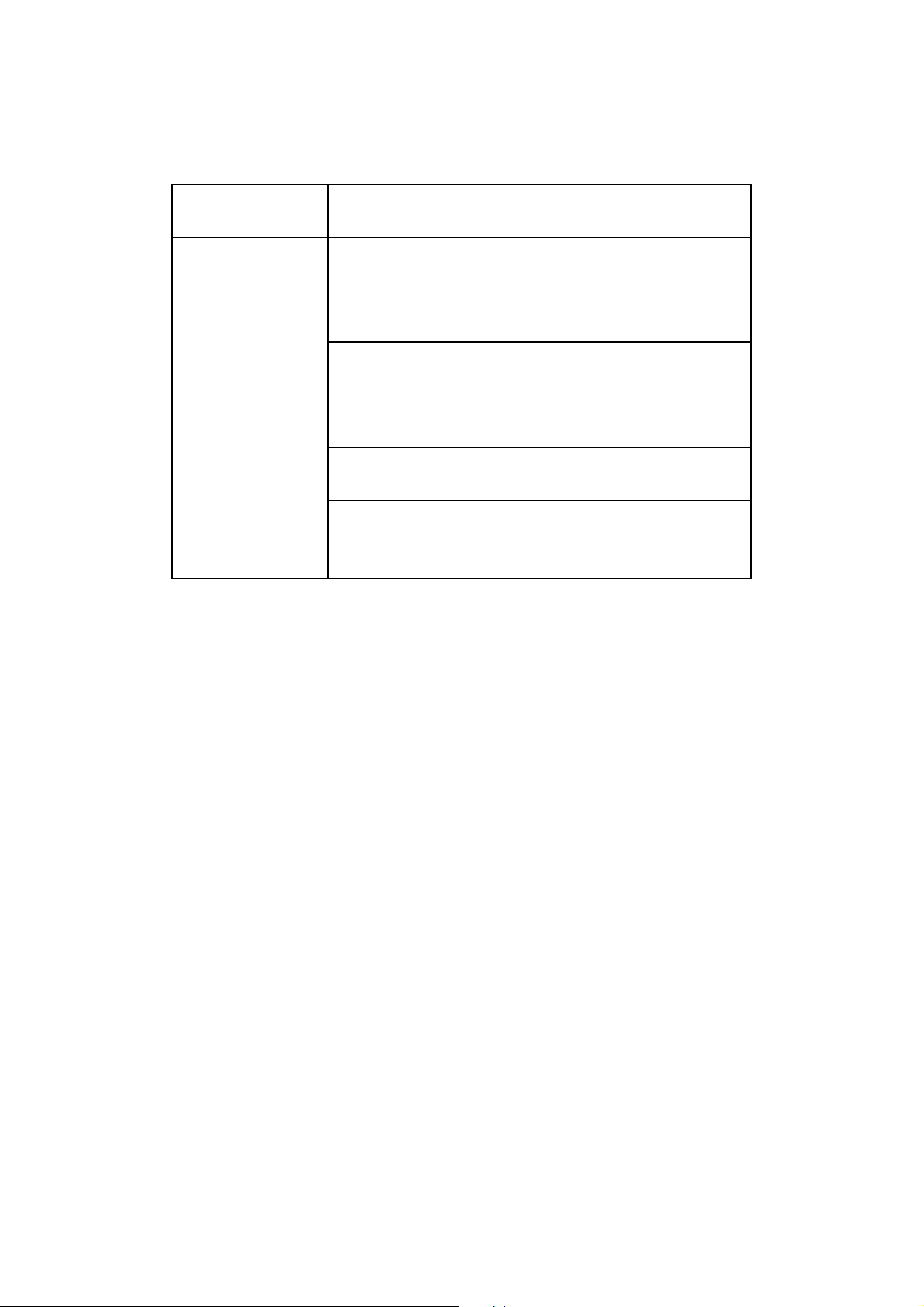
Accessories Instruction manual....................... 1 PC
Included Case holder with screw.................2 PCs
Optional Two wires pressure transmitters,
Accessories Model : TR-PS2W-xx BAR
* Range : 2, 5, 10, 20, 50, 100
400 BAR.
* Data Acquisition software,
SW-U801-WIN.
* RS232 cable, UPCB-02.
* USB cable, USB-01.
* Real time SD card datalogger
DL-9602SD
* GSM controller, GSM-889.
* Interface cable ( cable between meter
to GSM-889 ), GMCB-89.
4
Page 8
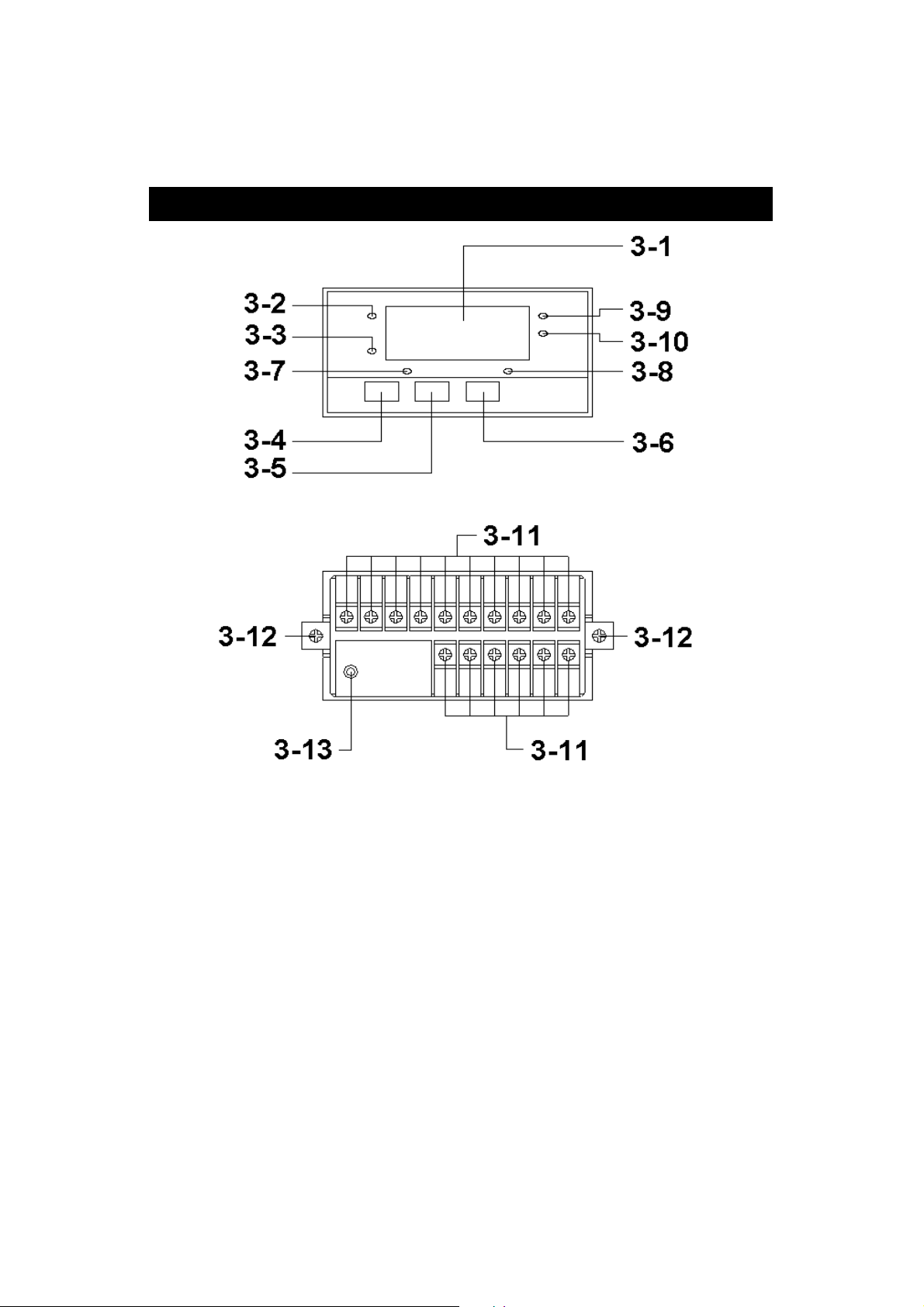
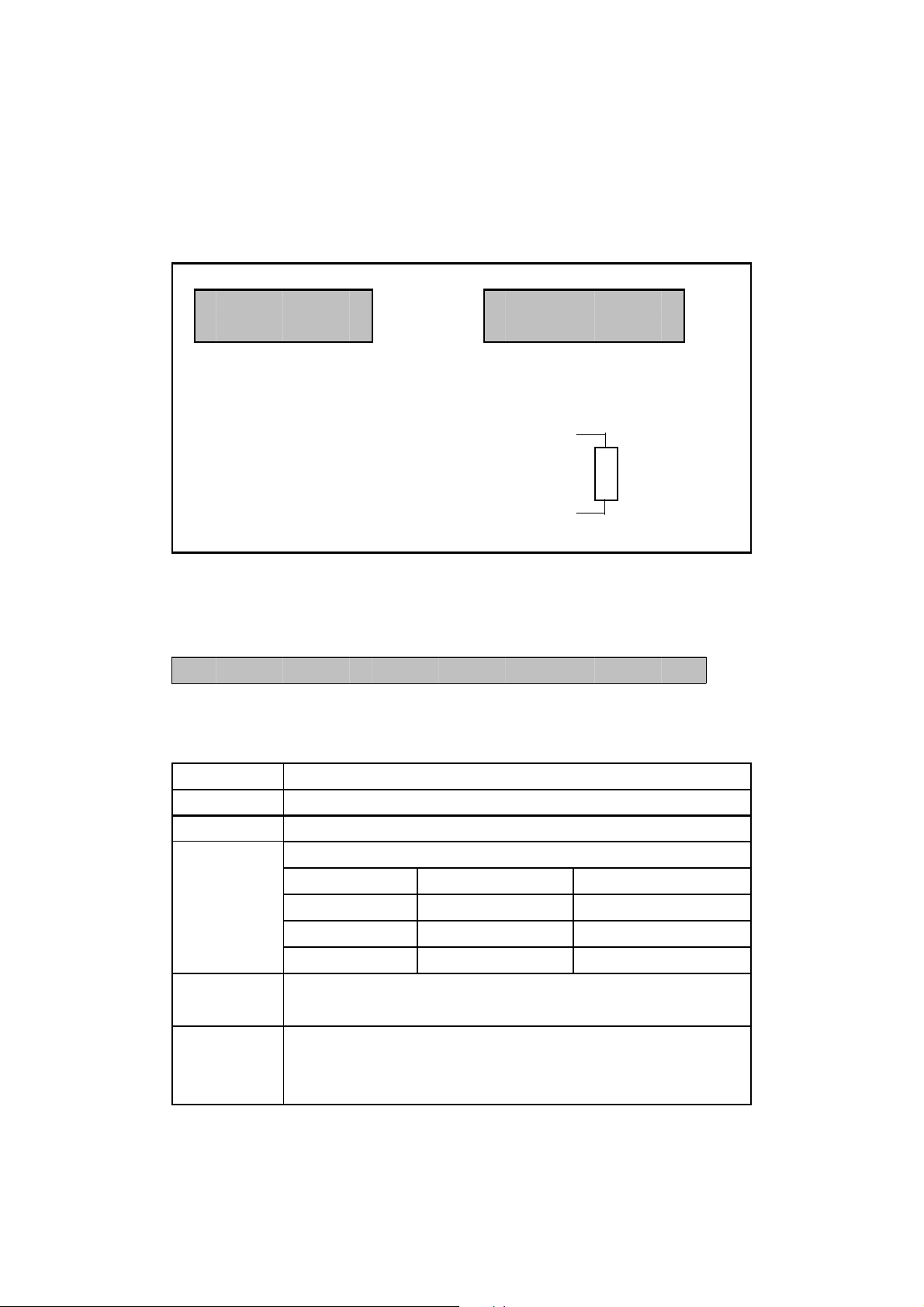
3. FRONT PANEL DESCRIPTION
Fig. 1
3-1 Display
3-2 PV ( process value ) indicator
3-3 SV ( set value ) indicator
3-4 Set Button
3-5 Button▼
3-6 Button▲
3-7 Control relay indicator
3-8 Alarm relay indicator
3-9 X10 indicator
3-10 X100 indicator
3-11 Wire terminals
3-12 Case holder
3-13 RS232 terminal
5
Page 9
4. MEASURING PROCEDURE
4-1 Terminal connection
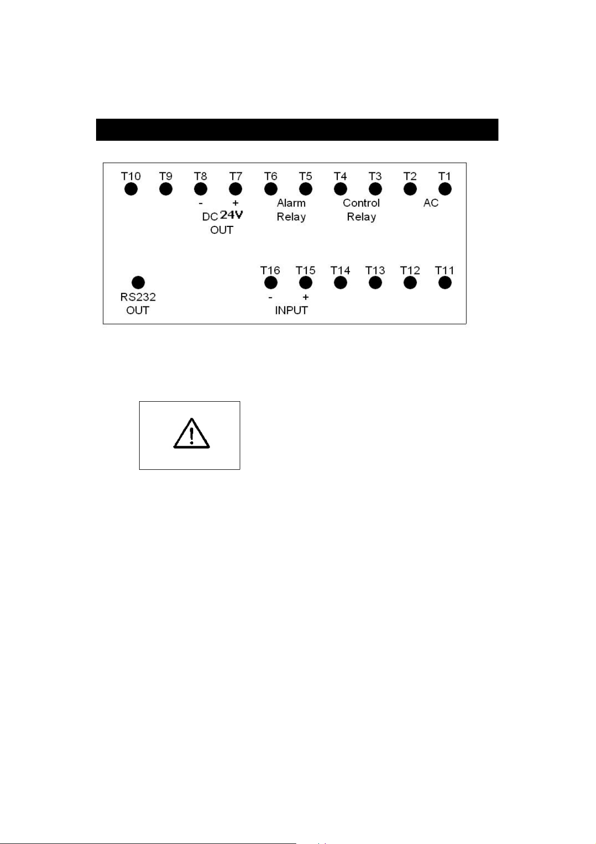
1)Input the ACV power ( 90 to 260 ACV ) to T1, T2.
Do not input the
over voltage to the
AC input terminals.
2)Connect the " Control Relay " output from T3, T4.
Connect the " Alarm Relay " output from T5, T6.
4-2 Pressure measurement
1)Prepare the optional two wires pressure sensors
( transmitters ), TR-PS2W-xxBAR.
or
the optional four wires pressure sensors ( transmitters ),
PS93MA--xxBAR.
6
Page 10
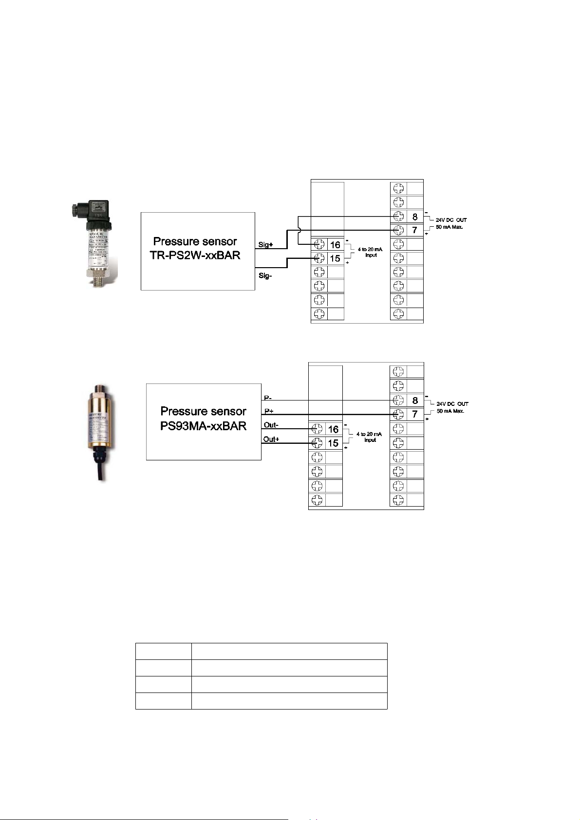
2)Make the wires installation as following :
3)Select the sensor type, please refer Chapter 4-2, page 10.
Select the sensor unit, please refer Chapter 4-2, page 14.
4-3 1st layer setting procedures
CtLo Control low value setting
CtHi Control high value setting
ALLo Alarm low value setting
ALHi Alarm high value setting
7
Page 11
Control low value setting
1)Press the " Set Button " ( 3-4, Fig. 1 ) once, the
" Display " will show " CtLo ", now the meter is ready
for the " Control low value " setting.
2)Use the " Button " ( 3-5, Fig. 1 ) and the " ▼▲
Button " ( 3-6, Fig. 1 ) to adjust the desiring " Control
low value ".
Remark :
* When adjust the value, the " SV indicator " ( 3-3, Fig. 1 )
will light.
Control high value setting
1)After set the " Control low value ", press the " Set
Button " ( 3-4, Fig. 1 ) twice, the " Display " will show
" CtHi ", now the meter is ready for " Control high value "
setting.
2)Use the " " Button " ( 3-5, Fig. 1 ) and the " ▼▲
Button " ( 3-6, Fig. 1 ) to adjust the desiring " Control
high value ".
Remark :
* When adjust the value, the " SV indicator " ( 3-3, Fig. 1 )
will light.
Alarm low Value Setting
1)After set the " Control high value ", press the " Set
Button " ( 3-4, Fig. 1 ) twice, the " Display " will show
" ALLo ", now the meter is ready for " Alarm low value "
setting.
8
Page 12
2)Use the " Button " ( 3-5, Fig. 1 ) and the " ▼▲
Button " ( 3-6, Fig. 1 ) to adjust the desiring " Alarm
low value ".
Remark :
* When adjust the value, the " SV indicator " ( 3-3, Fig. 1 )
will light.
Alarm high Value Setting
1)After set the " Alarm low value ", press the " Set
Button " ( 3-4, Fig. 1 ) twice, the " Display " will show
" ALHi ", now the meter is ready for " Alarm high value "
setting.
2)Use the " Button " ( 3-5, Fig. 1 ) and the " ▼▲
Button " ( 3-6, Fig. 1 ) to adjust the desiring " Alarm
high value ".
Remark :
* When adjust the value, the " SV indicator " ( 3-3, Fig. 1 )
will light.
4-4 2nd layer setting procedures
tyPE Sensor type
FiLt Digital filter
CtHy Control hysteresis set
ALHy Alarm hysteresis set
oFSt Offset adjustment
GAin Gain adjustment
Unit Unit set
9
Page 13
Sensor type setting
1)Press the " Set Button " ( 3-4, Fig. 1 ) continuously at
least two seconds, the " Display " will show " tyPE ",
now the meter is ready for the " Sensor type " setting.
2)Use the " Button " ( 3-5, Fig. 1 ) and the " Button "▼▲
( 3-6, Fig. 1 ) to adjust the desiring " Sensor type ".
Remark :
* The sensor type can select 8 types of pressure sensor :
2.000 Bar, 5.000 Bar, 10.00 Bar, 20.00 Bar,
50.00 Bar, 100.0 Bar, 200.0 Bar, 400.0 Bar
* The sensor type setting should correspond to the
optional pressure sensor that is used ( TR-PS2W-xxBAR ).
* When adjust the value, the " SV indicator " ( 3-3, Fig. 1 )
will light.
3)After finish the " Sensor type " setting, press the " Set
Button " ( 3-4, Fig. 1 ) once will save the sensor type
into the internal memory with default.
Digital filter setting
1)After finish the " Sensor type setting ", press the " Set
Button " ( 3-4, Fig. 1 ) once, the " Display " will show " FiLt "
, now the meter is ready for the " Digital filter " setting.
2)Use the " Button " ( 3-5, Fig. 1 ) and the " ▼▲
Button " ( 3-6, Fig. 1 ) to adjust the desiring
" Digital filter " value from 1 to 100.
* The more " Digital filter " value, will get more stable
value.
3)After finish the " Digital filter " setting,
Press the " Set Button " ( 3-4, Fig. 1 ) once will save the
Digital filter into the internal memory with default.
10
Page 14
Control Hysteresis value setting
1)After finish the " Digital filter setting ", press the " Set
Button " ( 3-4, Fig. 1 ) once, the " Display " will show
CtHy ", now the meter is ready for the " Control
Hysteresis value " setting.
2)Use the " Button " ( 3-5, Fig. 1 ) and the " Button "▼▲
( 3-6, Fig. 1 ) to adjust the desiring " Control
Hysteresis value ".
Remark :
* When adjust the " Control Hysteresis value " , the " SV indicator "
( 3-3, Fig. 1 ) will light.
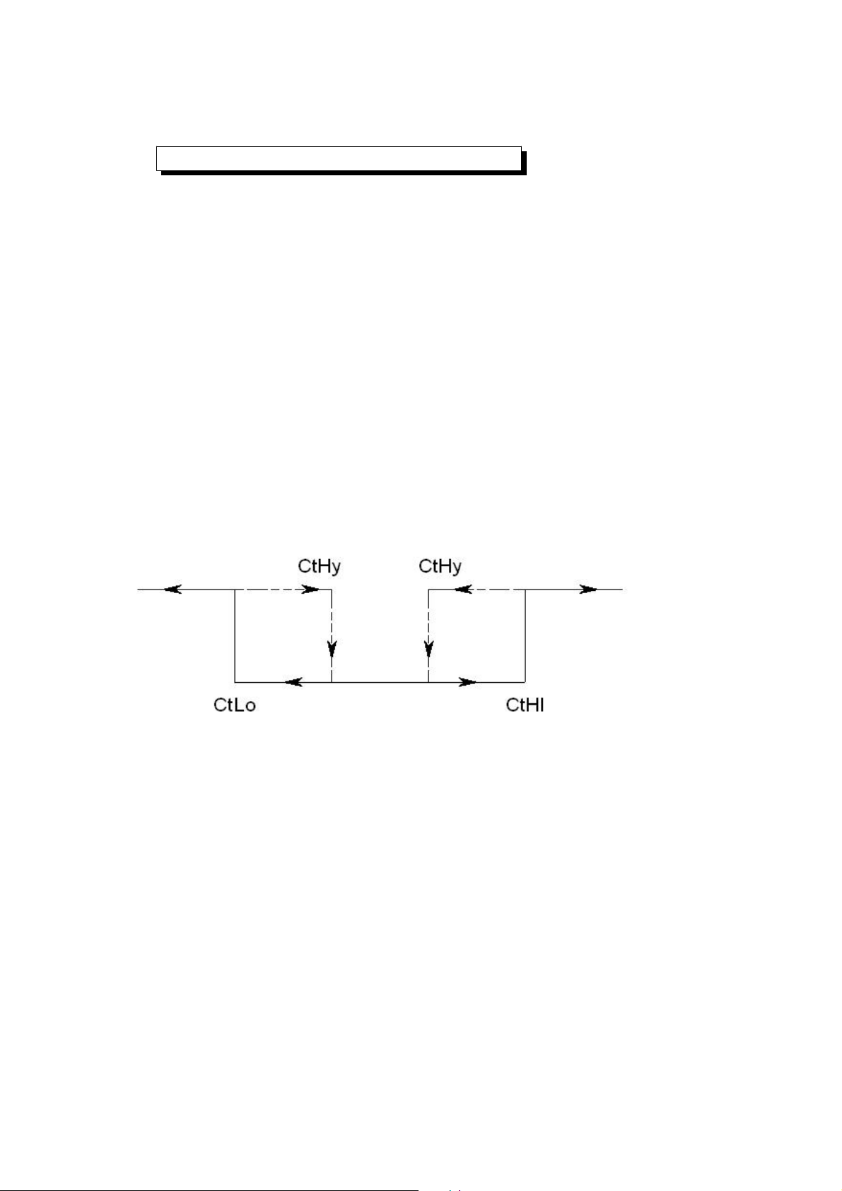
* The function of " Control Hysteresis value " setting, refer to
page 11, Fig. 3.
* For example : Fig. 3
Control High limit value ( CtHi ) : 500
Control Low limit value ( CtLo ) : 100
Control Hysteresis value ( CtHy ) : 5
a.The control relay will On when measuring value up
to 500. The control relay will Off again when
measuring value down to 495.
b.The control relay will On when measuring value
down to 100. The control relay will Off when
measuring value up to 105.
c. When the measuring value equal 0, control relay will Off.
11
Page 15
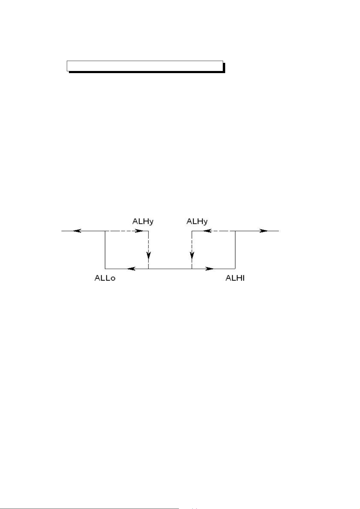
Alarm Hysteresis value setting
pag
1)After select the " Control Hysteresis value " , press the
" Set Button " ( 3-4, Fig. 1 ) twice, the " Display "
will show " ALHy ", now the meter is ready for the
the " Alarm Hysteresis value " setting.
2)Use the " Button " ( 3-5, Fig. 1 ) and the " Button "▼▲
( 3-6, Fig. 1 ) to adjust the desiring " Alarm Hysteresis
value " .
Remark :
* When adjust the " Alarm Hysteresis value " , the " SV indicator "
( 3-3, Fig. 1 ) will light.
* The function of " Alarm Hysteresis value " setting, refer to
e 12, Fig. 4.
* For example : Fig. 4
Alarm High limit value ( ALHi ) : 100
Alarm Low limit value ( ALlo ) : 20
* Alarm Hysteresis value ( ALHy ) : 5
a.The alarm relay will On when measuring value up
to 100. If the reading value > 100, the Display will
flashing. The alarm relay will Off again when
measuring value down to 95.
b.The alarm relay will On when measuring value down
to 20. If the reading value < 20, the Display will
flashing. The alarm relay will Off when measuring
value up to 25.
c. When the measuring value equal 0, alarm relay
will Off and the Display will flashing.
12
Page 16
Offset value adjustment
1)After finish the " Alarm hysteresis value setting " , press
the " Set Button " ( 3-4, Fig. 1 ) twice, the " Display "
will show " oFSt ", now the meter is ready for the "
Offset value adjustment " setting.
2)Use the " Button " ( 3-5, Fig. 1 ) and the " ▼▲
Button " ( 3-6, Fig. 1 ) to adjust the desiring
" Offset value ", press the " Set Button " ( 3-4, Fig. 1 )
to save the setting value.
Remark :
* During adjust the value, the " SV indicator " ( 3-3, Fig. 1 )
will light.
Gain value setting
1)After finish the " Offset value setting " , press the " Set
Button " ( 3-4, Fig. 1 ) once, the " Display " will show "
Gain ", now the meter is ready for the the " Gain value
adjustment " setting.
2)Use the " Button " ( 3-5, Fig. 1 ) and the " Button "▼▲
( 3-6, Fig. 1 ) to adjust the desiring " Gain value ",
press the " Set Button " ( 3-4, Fig. 1 ) to save the setting
value.
Remark :
* During adjust the value, the " SV indicator " ( 3-3, Fig. 1 )
will light.
* The Gain value setting range is 0.001 to 9.999, the default value
is 1.000.
13
Page 17
Unit setting
P
1)After finish the " Gain value setting " , press the " Set
Button " ( 3-4, Fig. 1 ) once, the " Display " will show "
Unit ", now the meter is ready for the the " Unit setting "
2)Use the " Button " ( 3-5, Fig. 1 ) and the " Button "▼▲
( 3-6, Fig. 1 ) to adjust the desiring " Unit no. " ( 0 to 9 ),
press the " Set Button " ( 3-4, Fig. 1 ) to save the
setting value.
Remark :
* The Unit no. setting is from 0 to 9, total 10 kind units can be selected.
0 : Bar 5 : PSI
1 : Kg/cm^2 6 : inch Hg
2 : mm Hg 7 : inch H20
3 : Meter H20 8 : hPa
4 : AT
( Atomsphere ) 9 : KPa
5. RS232 PC SERIAL INTERFACE
The instrument has RS232 PC serial interface via a 3.5
mm terminal ( 3-13, Fig. 1 ).
The data output is a 16 digit stream which can be
utilized for user's specific application.
14
Page 18
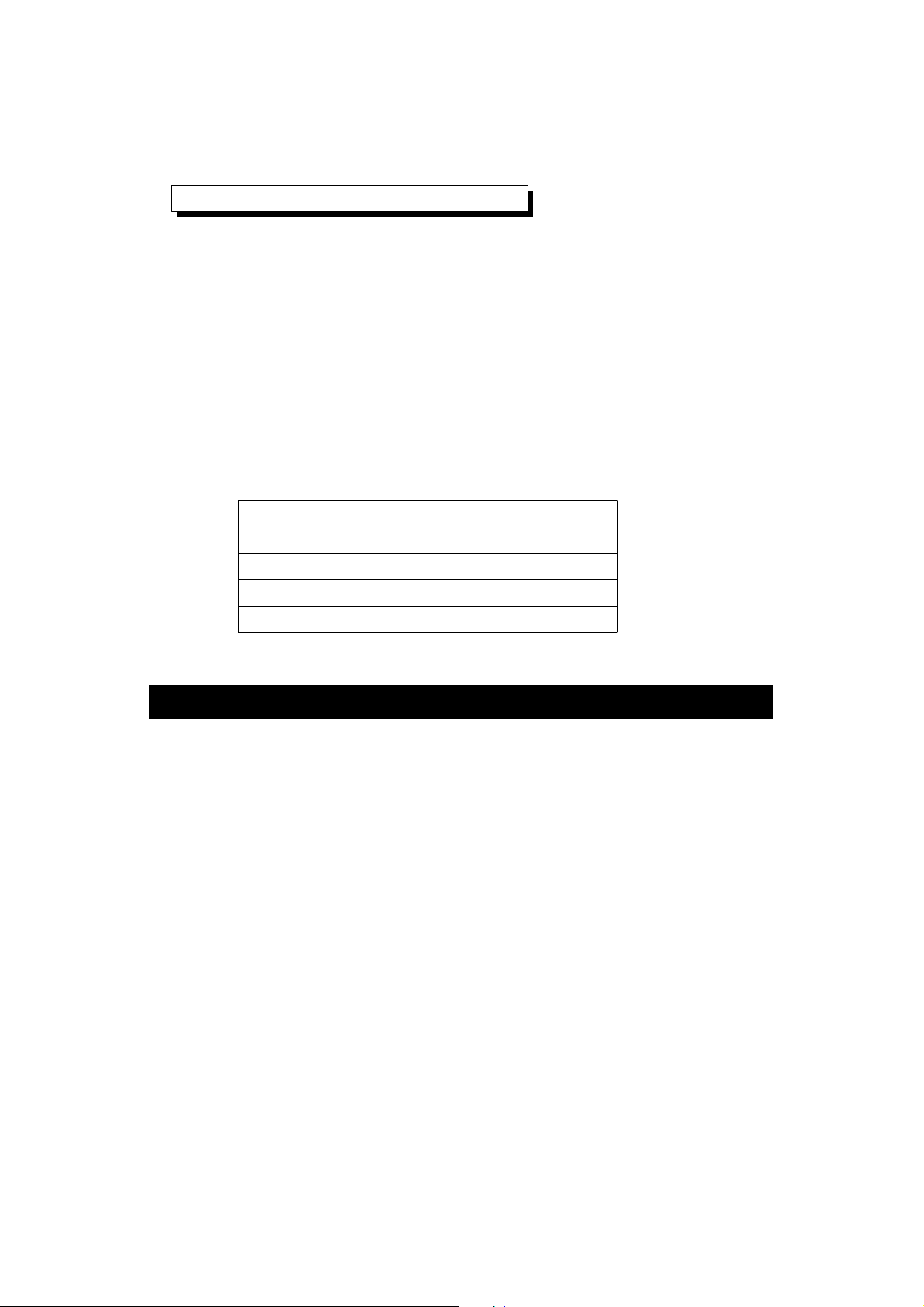
A RS232 lead with the following connection will be
required to link the instrument with the PC serial port.
Meter PC
(3.5 mm jack plug) (9W 'D" Connector)
Center Pin................................ Pin 4
Ground/shield..........................Pin 2
Pin 5
The 16 digits data stream will be displayed in the
following format :
D15 D14 D13 D12 D11 D10 D9 D8 D7 D6 D5 D4 D3 D2 D1 D0
Each digit indicates the following status :
D15 Start Word
D14 4
D13 1
D12 & D11 Annunciator for Display
Bar = 22 mm Hg = 78 inch H20 = 25
Psi = 23 inch Hg = 80 ATP = 26
hPa = 91 KPa = 88
Kg/cm^2 = 77 meter H20 = 79
D10 Polarity
0 = Positive 1 = Negative
D9 Decimal Point(DP), position from right to the
left
0 = No DP, 1= 1 DP, 2 = 2 DP, 3 = 3 DP
15
Page 19
D8 to D1 Display reading, D8 = MSD, D1 = LSD.
For example :
If the display reading is 1234, then D8 to
D1 is : 00001234
D0 End Word
RS232 setting
Baud rate 9600
Parity No parity
Data bit no. 8 Data bits
Stop bit 1 Stop bit
6. SYSTEM RESET
Power on the meter, use the two fingers to press " Set
Button " ( 3-4, Fig. 1 ) and " Button " ( 3-5,▼
Fig. 1 ) continuously more than 5 seconds until the
Display show the text " rSt ", release the buttons. After
" rSt " text flashing 2 times will return to the normal
screen. The meter system will be reset, all the
calibration data will be cleared, the meter's internal
function will return the default value.
7. OPTIONAL PRESSSURE SENSORS
( Optional 2 wires pressure
transmitters )
2 WIRES PRESSURE TRANSMITTER
Model : TR-PS2W-xxBAR
*Range : 2, 5, 10, 20, 50, 100, 400 BAR.
*Output : 4 to 20 mA DC.
4 mA = 0 pressure, 20 mA = full scale pressure
*2 wires, both for signal and power supply.
*Power : DC 9V to 30V.
16
Page 20
*Precision ceramic type pressure sensor.
*External zero and span adjustment.
*Output with socket, easy replacement.
*Allow high cable load resistance, transmitter
can install far away from the controller/indicator.
*Protection for the reverse wires connecting.
*TR-PS2W can cooperate the " Pressure
controller/monitor, PPS-9312 or the " 4-20 mA
Controller/Alarm/Indicator CT-2012 ".
8. THE ADDRESS OF AFTER SERVICE
CENTER
17
1304-PPS9312
 Loading...