

Page 1
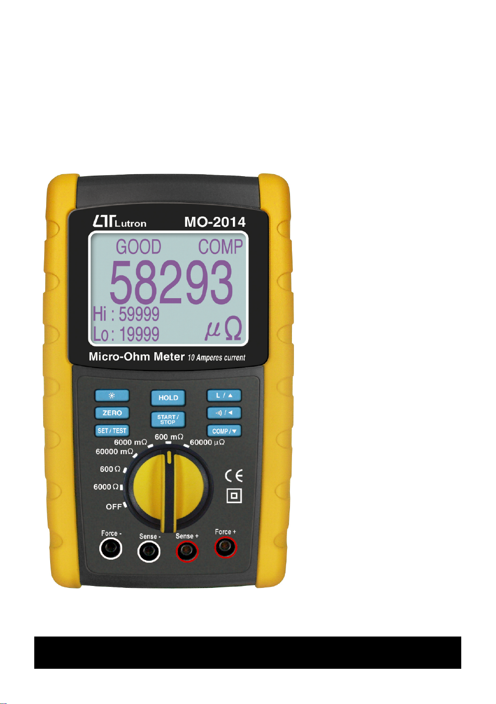
10 Amperes max. test current
r
Y
f
f
A
f
Micro-Ohm Mete
Model : MO-2014
our purchase o
this Micro-Ohm
METER marks a
step forward for
you into the field o
precision
measurement.
lthough this
Micro-Ohm METER
is a complex and
delicate instrument,
its durable structure
will allow many
years of use i
proper operating
techniques are
developed. Please
read the following
instructions
carefully and always
keep this manual
within easy reach.
OPERATION MANUAL
Page 2

TABLE OF CONTENTS
.
.
.
.
1. FEATURES...............................................................1
2. SPECIFICATIONS.....................................................1
2-1 General Specifications........................................
2-2 Electrical Specifications.......................................2
3. FRONT / REAR PANEL DESCRIPTION........................ 3
4. BASIC 4 WIRES MEASURING PRINCIPLE................... 4
5. PRECAUTION & PREPARATIONS FOR
MEASUREMENT.......................................................5
6. MEASURING PROCEDURES......................................
6-1 Buttons instructions ....................................... 5
6-2 Symbols & units of display.................................. 6
6-3 Resistance Measurement.................................... 6
7. HI / LO WARNING SETUP........................................
8. CALCULATE CABLE / WIRE LENGTH.........................
1
5
7
9
9. RS232 PC SERIAL INTERFACE.................................. 10
10. BATTERY REPLACEMENT........................................11
Page 3
1. FEATURES
j
s
*
4 terminal devices for accurate measurement of very
low resistance.
*
Ideal for measuring the resistance of components
precisely.
*
Ideal for testing protective conductors, lightning
conductors and welded points.
*
Maximum test current is 10A ( 60000 uΩ range only ).
*
Have two working mode , Resistive and Inductive mode,
Normal is resistive mode.
*
Good / Fail set-function for input quality control.
*
Built-in in buzzer sound (GOOD STATUS) to assist the Q.C.
udgment.
*
Especial "CALCULATE" function to measure cable /
wire length.
Wide measuring range, 5 u Ω - 6K Ω , 6 ranges.
*
*
Large size and back-light LCM display, easy read-out.
*
LSI circuit provides high accuracy, reliability and
durability.
*
Built-in over input protection.
*
Durable bench type housing plastic case stand.
2. SPECIFICATIONS
2-1 General Specification
Test Range 60000 uΩ ( 10 A DC )
(Test Current) 600 m Ω ( 1 A DC )
6000 mΩ ( 100 mA DC )
60000 mΩ ( 10 mA DC )
600 Ω ( 1 mA DC )
6000 Ω ( 100 uA DC )
Warning Setup * Warning LCD Indicator
* Buzzer
Operating Temp. 0 to 50 ( 32 to 122 ).℃℉
Operating HumidityLess than 80 % R.H..
Power Supply DC 1.5 V , AA (UM-3)Battery X 8 PCs .
AC to DC 9V Power adapter .
1
Page 4
Fuse protect * 10 A / 250 V
* Size : 6.3 X 32 mm dia..
Dimension 225 x 125 x 64 mm
( 8.86 x 4.92 x 2.52 inch)
Weight Approx. 790 g ( 1.74 LB ).
Standard 4 wire with 2 Kelvin clips........1 pair
Accessories Instruction Manual.................1 PC
AC/DC 9V power adapter........... 1 set
Optional * USB cable, USB-01.
Accessories * RS232 cable, UPCB-02.
* Data Acquisition software,
SW-U801-WIN., SW-E802.
* SD card data recorder, DL-9602SD
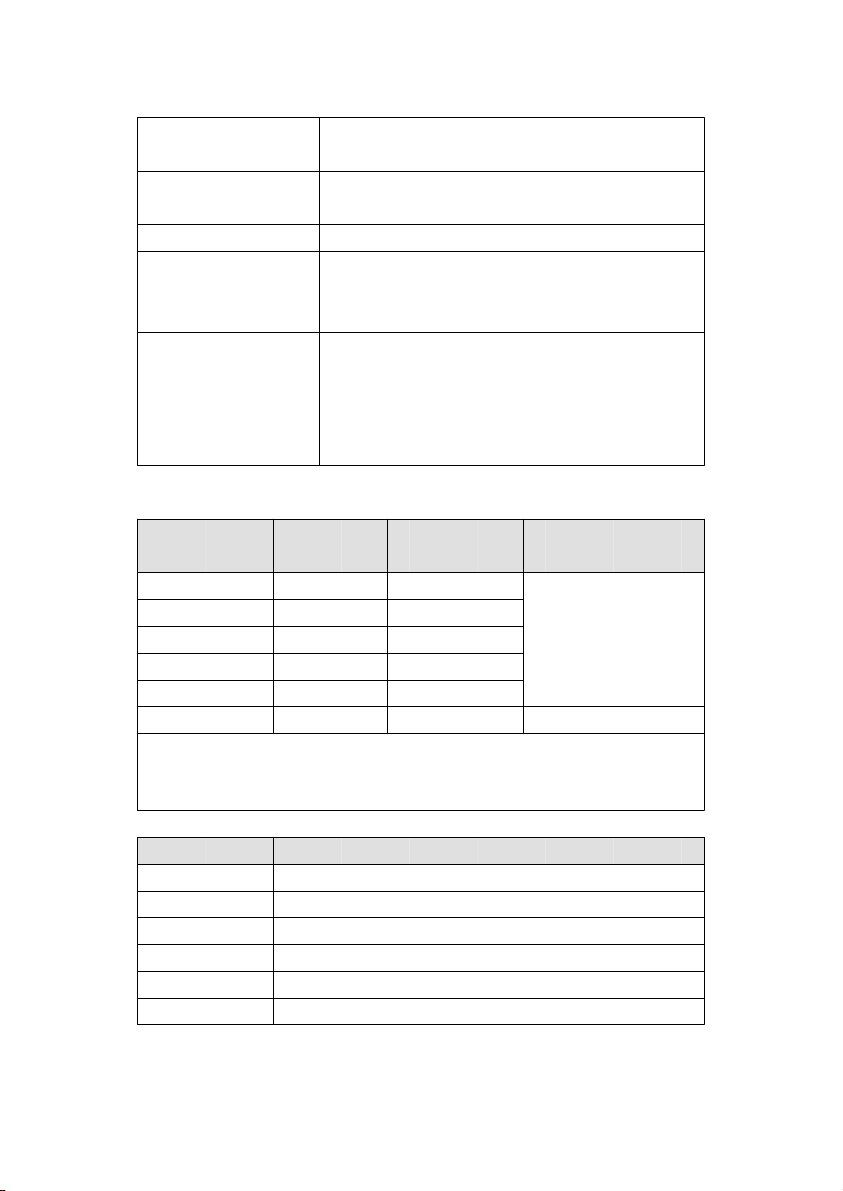
2-2 Electrical Specifications ( 23± 5 )℃
Range Resolution Test current Accuracy
60000 u Ω 1 u Ω 10 A
600 m Ω 10 u Ω 1 A
6000 mΩ 100 u Ω 100 mA ± ( 0.25 % + 25 d )
60000 mΩ 1000 u Ω 10 mA
600 Ω 10 mΩ 1 mA
6000 Ω 100 mΩ 100 uA ± ( 0.75 % + 3 d )
@ The above accuracy is based on the reading value.
@ Spec. tested under the environment RF Field Strength less
than 3 V/M & frequency less than the 30 MHz only.
Range Open Circuit Voltage
60000 u Ω Approx. DC 4.33 V
600 m Ω Approx. DC 4.33 V
6000 mΩ Approx. DC 4.33 V
60000 mΩ Approx. DC 4.33 V
600 Ω Approx. DC 4.33 V
6000 Ω Approx. DC 4.33 V
2
Page 5
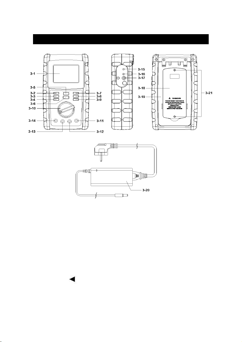
3. FRONT/REAR PANEL DESCRIPTION
3-9 COMP / key button▼
3-1 Display 3-11 Force Terminal "+"
3-2 Backlight key button 3-12 Sense Terminal "+"
3-3 Zero key button 3-13 Sense Terminal "-"
3-4 SET / TEST key button 3-14 Force Terminal "-"
3-5 HOLD key button 3-15 RS232 socket
3-6 START / STOP key button 3-16 Reset button
3-7 L / key button▲ 3-17 DC 9V power adapter socket
3-8 Beep / key button 3-18 Battery Cover / Battery
3-10 Power / Range rotary 3-19 Stand
switch 3-20 AC/DC 9V power adapter
Fig. 1
compartment
3-21 Battery cover screws
3
Page 6
4. BASIC 4 WIRES MEASURING
T
T
PRINCIPLE
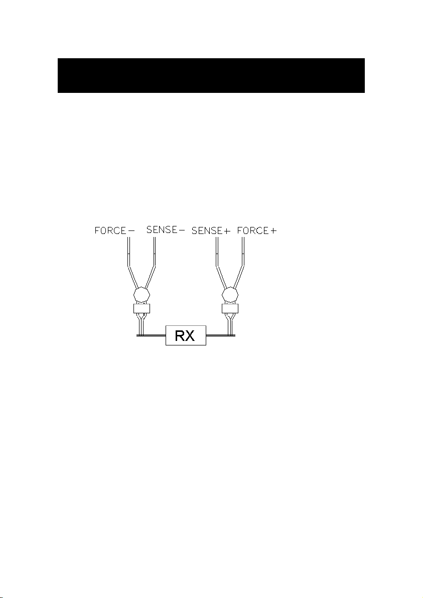
The DIGITAL MICRO-OHM METER is a precise,
wide range, small resistance and high resolution
measuring instrument. As for preventing any measuring
errors, especially to avoid the influence of "LEAD STRAY
RESISTANCE" or "TEST WIRE'S RESISTANCE", the
meter is designed according to the following "4 WIRES
MEASURING PRINCIPAL" to maintain the meter in
high accuracy.
Fig. 2
Please refer to 2-2 Electrical Specification ( page 2 ),
*
each range exists fixed test current ( from 6000 Ω to
60000 uΩ .
he fixed current flow through the unknown resistor Rx.
*
From the terminal " Sense + " and " Sense - " can measure
*
a voltage Vx = Is x Rx.
According the Vx value, then meter can get the unknown
*
resistance (Rx) values from following formula :
Rx = Vx / Is
he measured resistance value between "Sense +" and
*
"Sense -"is not affected by any stray resistance of test wire.
4
Page 7
5. PRECAUTION & PREPARATIONS FOR
n
BEEP/ Press this key to open / close buzzer
Button function.
MEASUREMENT
Please check carefully the meter's power supply is DC
*
9V power adapter before operating at 60000 uΩ range .
It's prohibited to input voltage to the 4 wire input
*
terminal ( Force +, Sense +, Sense -, Force - ) to
prevent any internal circuit damage.
6. MEASURING PROCEDURES
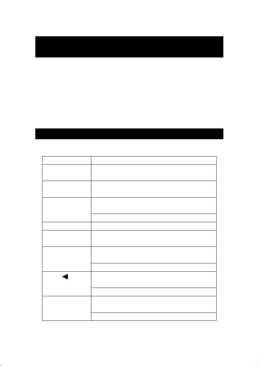
6 -1 Buttons instructions
Buttons
Backlight Press this key to turn backlight on and
Button off.
ZERO Button When the display indicate few reading
SET/TEST Press this key to do HI / LO limit
Button setup.
HOLD Button Press this key to do data hold .
START/STOP Press this key to starting measurement
Button or stop.
L/ Button▲
Functio
before measure .
Press this key return to TEST status.
Press this key to setting work mode
(Resistive or Inductive).
Press this key to adjust up value.
COMP / ▼
Button status judgment.
Press this key to select digit unit.
Press this key to start "GOOD , FAIL "
Press this key to adjust down value.
5
Page 8
6 -2 Symbols & units of display
n
:
f
e
D
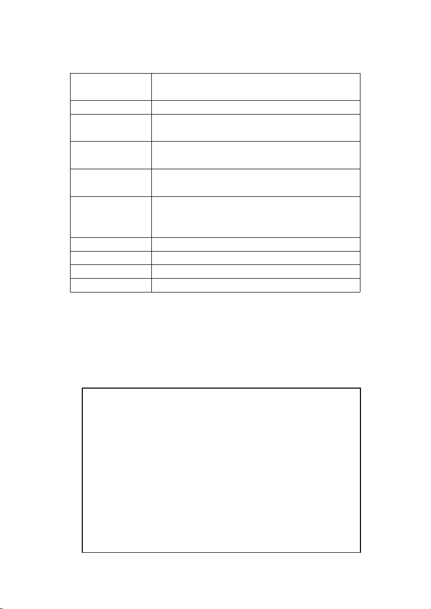
Symbol &
Functio
Unit
uΩ ,mΩ ,Ω
.)))
HOLD
GOOD
FAIL
COMP
L
H I
LO
Ohm unit
Appears on the "BEEP" function have
started.
Appears on the"HOLD" function have
started.
It is pass Q.C. Appears on finished
compare operate.
It is higher or lower than maximum or
minimum acceptance value . Appears
on finished compare operate.
Appears on the"COMPARE" function.
Appears on the"INDUCTIVE" mode.
Appears to showing H I limit.
Appears to showing LO limit.
6 -3 Resistance Measurement
Power on the instrument by rotate the "Power /
1)
Range rotary switch" ( 3-10, Fig. 1 ) to exit the " OFF "
position and then select measuring range from 60000 uΩ
to 6000 Ω according to your requirement.
Note
Always select the highest range ( 6000 Ω
*
) if you don't know the resistance value o
the resistor and then select lower rang
in sequence.
At 60000 uΩ ( 10A )must use DC 9V
*
adapter from socket ( 3-17, Fig. 1 ).
Over range LCD shows " ----- ".
*
Can't measure the resistance value, LC
*
will show 0.0000, 0.000 or 0.00.
6
Page 9

Connect the
T
2)
* Red cable ( with white O ring marker ) to " Force + "
terminal ( 3-11, Fig. 1 )
* Red cable ( no white O ring marker ) to " Sense + "
terminal ( 3-12, Fig. 1 )
* Black cable ( with white O ring marker ) to " Force - "
terminal ( 3-13, Fig. 1 )
* Black cable ( no white O ring marker ) to " Sense - "
terminal ( 3-14, Fig. 1 )
3)Connect the 2 Kelvin clips as following Fig. 3 to measure
the unknown resistance.
4)Press the "START / STOP" key ( 3-6, Fig. 1 ) will start
measure the unknown device.
Press once again will stop measure function and
froze the result at LCM.
5)When your tested material has inductive, you can press
" L/ " key ( 3-7, Fig. 1 ) for change to inductor mode▲
( at 600 mΩ and 60000 uΩ range) , Display will showing
" L " mark. normal is resistor mode.
7. HI/LO WARNING SETUP
This instrument has Hi, Lo warning value setup function
and a buzzer which are specially designed for quality
control.
Primary to press the " SET / TEST " ( 3-4, FIG. 1 )
button enter setting mode.
1) Hi warning value setup
he last digit should flash at " H i warning value " on
the display . Then press " L / " buttons ( 3-7, Fig.▲
1 ) to increase or " COMP / " buttons ( 3-9, Fig. 1 )▼
to decrease digit that you want to alter large value,
7
Page 10
press the " BEEP / " buttons (3-8 , Fig. 1) set
warning value , When user to move 1st digit unit to
T
T
Press " BEEP / " ( 3-8, Fig 1) button once
will start buzzer, press once again to disable
next digit unit (10th, 100th. 1000th).
* Hypothesize display be set at 180.00 .
2) LO warning value setup
Finished (1) procedure then press the " SET / TEST "
button ( 3-4, Fig. 1 ) again, The last digit should flash
at " LO warning value " on the display . Other
operate way same above explain.
* Hypothesize display be set at 179.00 .
Finished (1)(2) procedure then press the " SET /
3)
EST " button ( 3-4, Fig. 1 ) once . The function
should return to TEST MODE and indicate measure
value when clipping the resistor.
When measuring period press " COMP / " ( 3-9 ,▼
4)
Fig. 1) button once, The display will show " GOOD "
or " FAIL " symbol to inform be measure results.
For example
he value was readout 179.50 , The display
a.
should show " GOOD " symbol and buzzer sounds.(
If buzzer function have been press on status, The
buzzer sounds can to assist Q.C judgment ) The
resistance value within the accuracy Pass the Q.C.
*
" BEEP " function.
b.The value was readout 180.10 or 178.60, The
display should show " FAIL " symbol, The
resistance value out of the accuracy.
8
Page 11

8. CALCULATE CABLE/WIRE LENGTH
Before calculate cable length . You should sampling one
unit length (meter or feet).
1)Primary to take one sample from a lot of cable or
wire then to to measure 1 m or 1 feet length - unit.
2)Measue the unknown cable . wait a moment unitl the
reading have been stable . Stop the measure action
and hold the range.
3)Press " HOLD " button ( 3-5, Fig. 1 ) to release HOLD
status.
4)Press " SET / TEST " button ( 3-4 , Fig.1) more than
three secoends into sample unit mode.
5)Then press " L / " button ( 3-7 , Fig.1) or " COMP /▲
" button( 3-9 , Fig.1) to select unit (meter or feet).▼
6)Press " START / STOP " button ( 3-6 , Fig.1) to
sampling unit value.
7)Press " SET / TEST " button ( 3-4 , Fig.1) to save the
value and showing the cable length .
Now is already measurement unknown cable length.
8)Once press "SET / TEST" button ( 3-4 , Fig.1) more
than 3 secend . Will return to measure mode .
9
Page 12
9. RS232 PC SERIAL INTERFACE
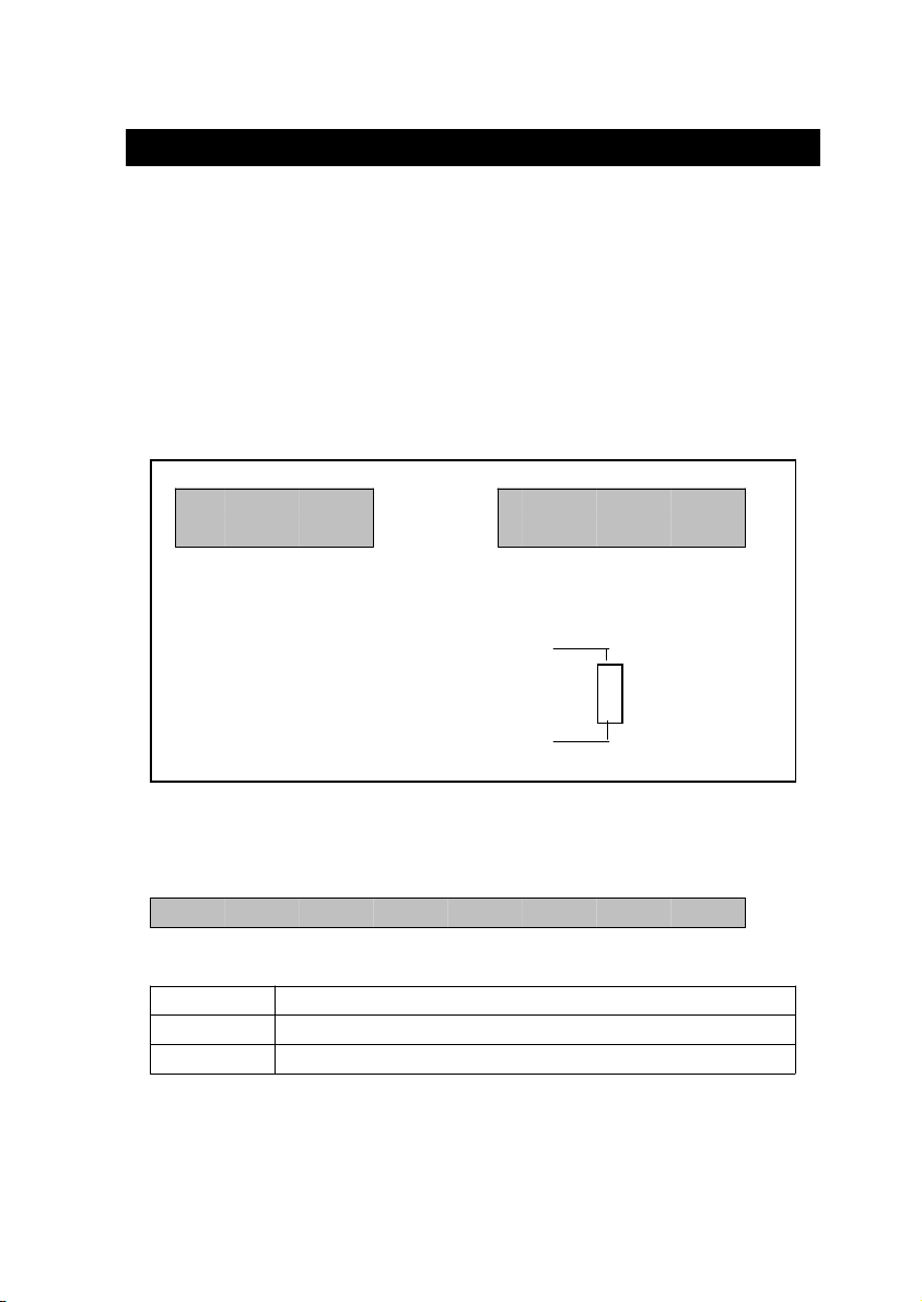
The instrument has RS232 PC serial interface via a 3.5
mm terminal ( 3-15, Fig. 1 ).
The data output is a 16 digit stream which can be
utilized for user's specific application.
A RS232 lead with the following connection will be
required to link the instrument with the PC serial port.
Meter PC
( 9W " D" Connector)
Center Pin..........................Pin 4
(3.5 mm jack plug)
Ground/shield.......................Pin 2
2.2 K
resistor
Pin 5
The 16 digits data stream will be displayed in the
following format :
D15 D14 D13 D12 D11 D10 D9 D8 D7 D6 D5 D4 D3 D2 D1 D0
Each digit indicates the following status :
D15 Start Word, 02
D14 4
D13 1
10
Page 13
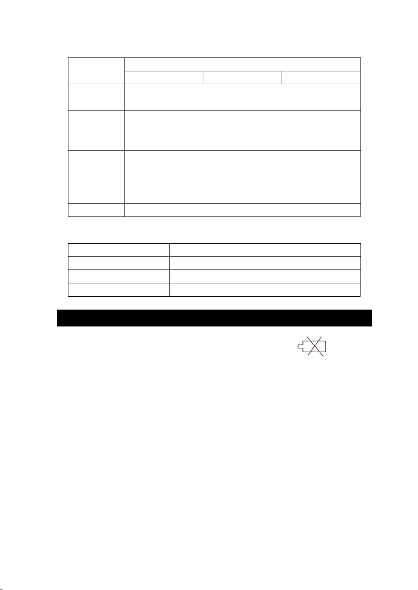
D12, D11 Annunciator for Display
T
When the left corner of LCD display show " ", it
is necessary to replace the battery. However, in-spec.
Ω = 38 mΩ = B1 uΩ = F5
D10 Polarity
0 = Positive 1 = Negative
D9 Decimal Point(DP), position from right to the
left
0 = No DP, 1= 1 DP, 2 = 2 DP, 3 = 3 DP
D8 to D1 Display reading, D1 = LSD, D8 = MSD
For example :
If the display reading is 1234, then D8 to
D1 is : 00001234
D0 End Word, 0D
RS232 FORMAT : 9600, N, 8, 1
Baud rate 9600
Parity No parity
Data bit no. 8 Data bits
Stop bit 1 Stop bit
10. BATTERY REPLACEMEN
1)
measurement may still be made for several hours after
low battery indicator appears before the instrument
become inaccurate.
2)Loose the " Battery Cover Screws " ( 3-21, Fig. 1 )
and take away the " Battery Cover " ( 3-18, Fig. 1 )
from the instrument and remove the battery.
3)Replace with DC 1.5 V battery ( UM3, AA,
Alkaline/heavy duty ) x 8 PCs, and reinstate the cover.
4)Make sure the battery cover is secured after changing
the batteries
11
1403-MO2014
 Loading...