

Page 1

HomeWorks QS Palladiom
Thermostat Configuration Guide
P/N 032498h
P/N 032498h
Page 2

P/N 032498h
Table of Contents
Description.............................................................................................................................................................................4
Step 1: Identify the HVAC Equipment and Confirm Device Installation .......................................................5
Identify the HVAC Equipment .............................................................................................................................................5
Confirm Device Installation .................................................................................................................................................5
Programming Menu Overview .......................................................................................................................................7
Step 2: Equipment Configuration Mode .................................................................................................................... 7
Step 3: Select the HVAC Controller .............................................................................................................................8
Step 4: Set the SMC55-HWQS Basic Parameters for System Compatibility ............................................9
(01b): System Type .............................................................................................................................................................11
(02b): Heat Stages .............................................................................................................................................................11
(03b): Run Auxiliary Heat (Aux/W2) With Other Heat Stages .......................................................................................... 12
(04b): Auxiliary Heat (Aux/W2) Upstage Delay .................................................................................................................12
(05b): Cool Stages .............................................................................................................................................................13
(06b): Heat Fan Control .....................................................................................................................................................13
(07b): Changeover / Revers ing Valve (O / B) Type..............................................................................................................13
(08b): Valve / Element Type ................................................................................................................................................ 14
(09b): Fan Type ...................................................................................................................................................................14
(10b): 2-Pipe Mode .............................................................................................................................................................15
(11b): Underfloor Heating Control ..................................................................................................................................... 16
Saving and Exiting Basic Configuration ........................................................................................................................... 17
Step 5: Set the SMC55-HWQS Advanced Parameters to Modify the Functionality of the HVAC System ...18
Parameters Applicable to All types of HVAC Equipment ................................................................................................22
(01A) Function Type ...................................................................................................................................................... 22
(02A) Temperature Sensor Type ....................................................................................................................................22
(06A) Minimum Fan On Time .........................................................................................................................................22
(07A) Extended Cool Fan Time (OCFT) ...........................................................................................................................22
(08A) Extended Heat Fan Time (OHFT) ..........................................................................................................................22
(11A) Cool Fan On Delay (CFOD)....................................................................................................................................22
(12A) Heat Fan On Delay (HFOD) ...................................................................................................................................22
(18A) Standalone Temperature Operation Mode .............................................................................................................22
(19A) Standalone Temperature Fan Mode.......................................................................................................................22
(30A) Cannot Reach Setpoint Timeout ...........................................................................................................................23
(31A) Cannot Reach Setpoint Action ..............................................................................................................................23
Parameters Applicable to Conventional and Heat Pump Systems ................................................................................23
(70A) Minimum Compressor Run Time (MCRT) ..............................................................................................................23
(71A) Minimum Compressor Off Time (MCOT) ................................................................................................................ 23
(74A) Heat Stage 1-On Delta .........................................................................................................................................24
(75A) Heat Stage 1-Off Delta .........................................................................................................................................24
(76A) Heat Stage 2 (Y2/W2/Aux)-On Delta .......................................................................................................................24
(77A) Heat Stage 2-Off Delta ......................................................................................................................................... 24
(78A) Heat Stage 3 (Aux)-On Delta ................................................................................................................................24
(79A) Heat Stage 3 (Aux)-Off Delta ................................................................................................................................24
(80A) Cool Stage 1-On Delta ......................................................................................................................................... 24
(81A) Cool Stage 1-Off Delta .........................................................................................................................................24
(82A) Cool Stage 2-On Delta .........................................................................................................................................24
(83A) Cool Stage 2-Off Delta.........................................................................................................................................25
(84A) Compressor Cool Stage 2 Upstage Delay (CC2SUD) ..............................................................................................25
(85A) Compressor Heat Stage 2 Upstage Delay (CH2SUD) ..............................................................................................25
(88A) Reversing Valve Delay (RVD) .................................................................................................................................25
Continued on next page...
2
Page 3

P/N 032498h
Table of Contents (continued)
Parameters Applicable for Radiant Underfloor Heating System ....................................................................................26
Radiant Underfloor Heating Control Summary ............................................................................................................26
Pulse Width Modulation (PWM) Temperature Control (for relay signals only) ...................................................................26
0–10 V- Control (for 0–10 V- signal only) .....................................................................................................................26
Duty Cycle Sample Adaptation (for both relay and 0–10 V- signals) ..............................................................................26
Parameter details ...........................................................................................................................................................27
(54A) Minimum Pulse Width ..........................................................................................................................................27
(90A) Slab Maximum .................................................................................................................................................... 27
(91A) Slab Minimum .....................................................................................................................................................27
(92A) Slab Setpoint ......................................................................................................................................................27
(93A) Floor 100% Differential ........................................................................................................................................27
(94A) Floor 0% Differential ............................................................................................................................................ 27
(95A) Cycles Per Hour (CPH) .........................................................................................................................................27
Parameters Applicable for 0–10 V- Fan Coil Units ........................................................................................................27
(50A) Proportional Fan Minimum ...................................................................................................................................27
(51A) Proportional Fan Low Speed ................................................................................................................................27
(52A) Proportional Fan Medium Speed ..........................................................................................................................27
(53A) Proportional Fan High Speed ...............................................................................................................................27
(54A) Minimum Valve Percent Open ...............................................................................................................................27
(55A) Valve Fully Open Differential ................................................................................................................................. 27
(56A) Non-proportional Analog Output ..........................................................................................................................27
Parameters Applicable for 2-pipe Fan Coil Units ............................................................................................................28
(40A) Change Over to Heat for Pipe Temperature ............................................................................................................28
(41A) Change Over to Cool for Pipe Temperature ............................................................................................................28
(42A) Enable Purge Function .........................................................................................................................................28
(43A) Purge Valve On-Time ...........................................................................................................................................28
(44A) Purge Valve Off-Time ...........................................................................................................................................28
Parameters Applicable to a FCU with Multi Speed Fan ..................................................................................................28
05A) Fan High Differential .............................................................................................................................................28
(09A) Kick-Start Fan .....................................................................................................................................................28
Step 6: Verification ...........................................................................................................................................................29
Troubleshooting .................................................................................................................................................................30
Appendix A ...........................................................................................................................................................................31
1. Heat Stage Relays .........................................................................................................................................................31
2. Cool Stage Relays .........................................................................................................................................................31
3. Control Diagrams for Turning On / Off Different Heat and Cool Stages .....................................................................32
Appendix B: Installation Worksheet ..........................................................................................................................35
Appendix C: User Interface for the Thermostat...................................................................................................39
Appendix D: Reenter Configuration Menus ...........................................................................................................40
Appendix E: Determine Firmware Version (optional) .........................................................................................40
3
Page 4

P/N 032498h
Description
This programming guide provides information on how to configure the HomeWorks QS Palladiom Thermostat and
HomeWorks QS Palladiom HVAC controller (SMC55-HWQS, SMC55-RESI). All the references made to SMC55-HWQS
throughout the document will apply to SMC55-RESI as well.
The HomeWorks QS Palladiom thermostat and SMC55-HWQS are a two-piece solution offered by Lutron to control HVAC
equipment. The thermostat provides the user interface and the SMC55-HWQS sends signals to control the HVAC equipment.
The SMC55-HWQS must be configured correctly to control the HVAC equipment. The thermostat can also connect to third-party
HVAC controllers, or be used as a Companion Thermostat, which is described in later sections.
WARNING
This guide illustrates multiple steps for configuring the Palladiom thermostat and HVAC controller.
Step 1 illustrates how to identify the HVAC equipment and confirm system compatibility.
Step 2 covers the equipment configuration mode.
Step 3 explains the controller selection menu.
Step 4 details the basic parameters required to configure the SMC55-HWQS for compatibility.
Step 5 covers the details of the advanced parameters for the SMC55-HWQS which are used to modify the functionality of the
HVAC equipment. Advanced parameters are set to a default value and should only be changed if the system needs further
configuration.
After configuring both the basic and the advanced parameters, refer to Step 6 to verify the basic system functionality based
on the configuration of the SMC55-HWQS.
Appendix A includes control diagrams to explain the On/Off deltas for heating and cooling stages.
Appendix B provides a worksheet which should be kept and used by the installer during installation. Before configuring the
SMC55-HWQS, write the necessary values for the basic and advanced parameters in the allotted space.
Appendix C gives more details about the functionality of different buttons and user interface on the thermostat.
Shock Hazard - Improper configuration can cause property damage, personal injury, or death. Installation and
service must be performed by a licensed professional HVAC installer (or equivalent) or service agency.
4
Page 5

P/N 032498h
Step 1: Identify the HVAC Equipment and Confirm Device Installation
Identify the HVAC Equipment
First, identify the type of HVAC equipment that is installed. Check the installation manual or label on the HVAC equipment.
The Palladiom Thermostat solution is compatible with most residential HVAC systems, including:
1. Conventional forced air systems using gas, electric, or oil heat as well as compressor-based, cooling-only as split systems or
packaged units.
2. Fan Coil Units (FCUs)
3. Heat-pump systems
4. Hydronic or electric underfloor/radiant heating systems 1
5. Specific VRF/VRV systems. See the HomeWorks QS Palladiom Thermostat specification (Lutron P/N 3691033) at
www.lutron.com for further information.
Confirm Device Installation
Confirm the Palladiom Thermostat is installed. For hardware installation and wiring details, refer to the HomeWorks QS
Thermostat Installation Guide at www.lutron.com/TechnicalDocumentLibrary/043495.pdf. If connecting a third-party HVAC
controller to the thermostat, refer to the controller’s installation guides to confirm installation of the controller. Connecting the
Palladiom thermostat to third-party controllers is explained in the following Lutron app notes:
Daikin® VRV Systems and Other VRF Systems
Requires one of these hardware options:
• HomeWorks QS Palladiom thermostat and CoolAutomationTM CoolPlug interface. 2 See Application Note #660 (048660) at
www.lutron.com
• HomeWorks QS Palladiom thermostat with HomeWorks QS processor and CoolAutomationTM interface.
See Application Note #650 (048650) at www.lutron.com
Mitsubishi® VRF Systems
Requires one of these hardware options:
• HomeWorks QS Palladiom thermostat and Mitsubishi® Procon A1M interface. 2 See Application Note #661 (048661) at
www.lutron.com
• HomeWorks QS Palladiom thermostat with HomeWorks QS processor and CoolAutomationTM interface. 2
See Application Note #650 (048650) at www.lutron.com
• HomeWorks QS Palladiom thermostat with HomeWorks QS Palladiom HVAC controller and Mitsubishi® thermostat controller
inter face. 2 See Application Note #585 (048585) at www.lutron.com
LG® VRF Systems
Requires one of these hardware options:
• HomeWorks QS Palladiom thermostat and LG® PDRYCB500 interface. 2 See Application Note #662 (048662) at www.lutron.com
• HomeWorks QS Palladiom thermostat with HomeWorks QS processor and CoolAutomationTM interface. 2
See Application Note #650 (048650) at www.lutron.com
• HomeWorks QS Palladiom thermostat with HomeWorks QS Palladiom HVAC controller and LG® thermostat controller interface. 2
See Application Note #627 (048627) at www.lutron.com
Underfloor Heating Systems with Heatmiser Interface
Requires:
• HomeWorks QS Palladiom thermostat with HomeWorks QS processor and Heatmiser interface.
Integration with HomeWorks QS document.
1
Included with SMC55-HWQS version 7420 or newer, SMC55-RESI version 7302 or newer and HomeWorks Palladiom Thermostat version 1.10 or newer.
2
Provided by others.
3
For information about additional CoolAutomation interfaces, see www.coolautomation.com
Continued on next page...
1
2,3
2
See Heatmiser HVAC
5
Page 6
P/N 032498h
Step 1: Identify the HVAC Equipment and Confirm Device Installation
(continued)
Confirm Device Installation
(continued)
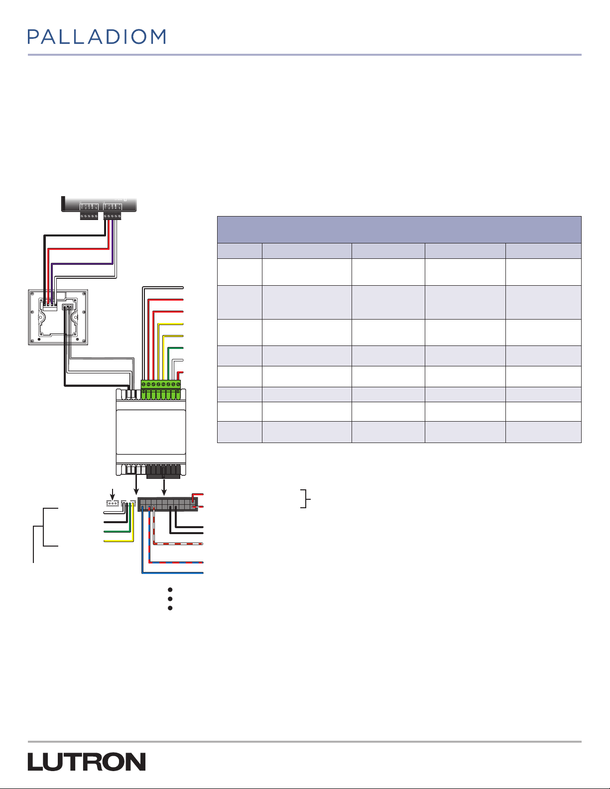
If connecting the Palladiom Thermostat to the SMC55-HWQS, they must be connected over the HVAC controller communication
link. Refer to Figure 1 for the wiring required to install the SMC55-HWQS with the thermostat. For hardware installation and
wiring details refer to the HomeWorks QS Thermostat Installation Guide (P/N 043495) at www.lutron.com.
Figure 1: SMC55-HWQS Setup for Configuration Using a Thermostat
HomeWorks QS
processor
Relay Terminals
SPST(NO) 1 A 24 V~ maximum relays
Terminal Conventional Heat Pump
#5 Heat stage 1 (W1)
Heating stage1
#6
transformer (RH)
Cooling / compressor
#7
transformer (R
)
C
#8 Compressor stage1 (Y
Compressor stage2
#9
1
(Y
)
2
Changeover heat
pump valve (O/B)
Heating
transformer(RH)
Cooling
transformer(RC)
Compressor
)
1
stage 1(Y1)
Compressor
stage 1(Y2)
1
Fan Coil Unit Radiant Floor
Hot valve (H
Heat valve
transformer(RH) or
Valve transformer(R)
Fan transformer (R
) Heat stage 1 (W1)
VALVE
Heat stage 1
transformer (R1)
) –
FAN
Fan high (G3) –
Fan medium (G2) –
#10 Fan (G) Fan (G) Fan low (G1) –
#11 Heat stage 2 (W
#12
Heating stage2
transformer (R
1
)
2
1
)
H2
Auxiliary heat (AUX) Cold valve (C
Auxiliary heat
transformer(R
AUX
)
Cold valve
transformer (RC)
) –
VALVE
2
–
43
21
Common
V+
MUX
_
HomeWorks
QS Palladiom
thermostat
Gray (G) Com
White (+) MUX
Black (−) _
QS Link
Power and
communication
#5
#6
#7
#8
#9
#10
#11
#12
HomeWorks QS
Palladiom HVAC
Controller
Not used
HVAC Controller Power (from HVAC system transformers)
24 V~ IEC / SELV / PELV / NECR Class 2
White (heat)
Black (common)
Green (fan)
Yellow (cool)
43G5
Red (R
AO
) Heat transformer
H
Gray /Red (C) Common
Black
Black
Orange / White (connect to black common wire for additional HVAC controllers only. This connection will set
the Modbus address to 02)
Wire harness for 0–10Vvalves and fan controls
Blue / Red (FCU changeover sensor or radiant floor slab sensor)
Blue (remote temperature sensor)
Optional signal wires
1
Included with SMC55-RESI version 7302 or newer and HomeWorks Palladiom Thermostat version 1.10 or newer.
2
Included with SMC55-HWQS version 7420 or newer and HomeWorks Palladiom Thermostat version 1.10 or newer.
6
Page 7
P/N 032498h
Programming Menu Overview
1. Equipment configuration mode: Indicates if 1 or 2 HVAC equipment types are used and what equipment is connected.
2. HVAC controller selection mode: Indicates what type of HVAC controller is being used and sets the address for it (if needed).
3. Basic configuration mode: Configures the HVAC controller according to the type of HVAC system.
Note: Depending on the options selected, certain programming modes may be skipped. It may be necessary to enter certain
programming modes twice if there are two equipment types. The thermostat will only display menus that are relevant to the
configurations selected.
4. Advanced configuration mode (Optional)
Step 2: Equipment Configuration Mode
Included with thermostat version 3.0 or later
WARNING
1. Enter equipment configuration mode. When a thermostat receives power, it will automatically enter equipment configuration
mode if equipment configuration has not been previously completed.
If no HVAC controller is going to be connected directly to the thermostat, skip this section. This is known as a companion thermostat
and configuration will be completed by a certified Lutron dealer via the HomeWorks QS designer software.
2. Select value for equipment configuration: Select the configuration option which describes the HVAC equipment
connected to the thermostat. Using the table below, press or to select the correct equipment configuration being used
and press and hold to save the configuration. The thermostat will then enter HVAC controller selection mode for the first zone.
Shock Hazard. Improper configuration can cause property damage, personal injury, or death. Installation and
service must be performed by a licensed professional HVAC installer (or the equivalent) or service agency.
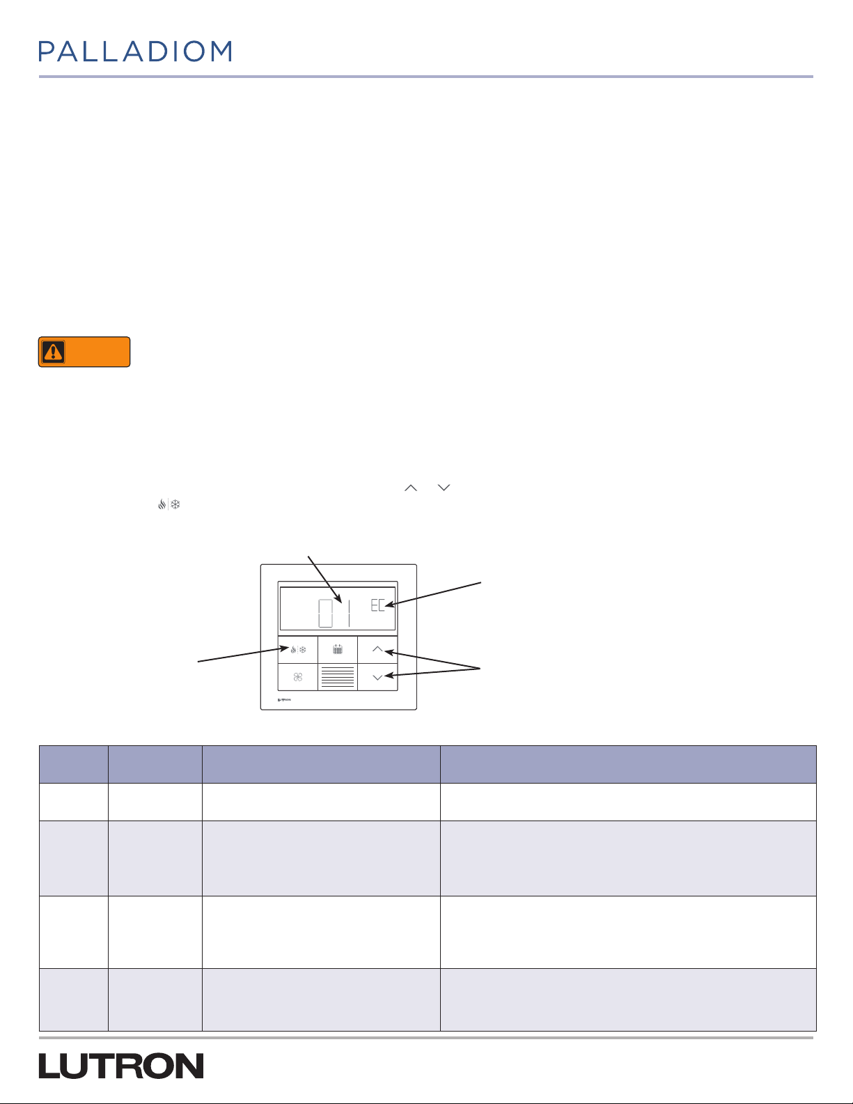
Figure 2: Display on Thermostat in Equipment Configuration Mode
Parameter value
Set
Hold 3 seconds to save and
exit configuration mode.
Table 1: Options for Equipment Configuration
Parameter
Value
01 1
02
03
Equipment
Typ e
2 – both heating
and cooling
equipment
connected to the
thermostat
2 – only heating
equipment
connected to the
thermostat
Description System Example
There is a single piece of equipment attached
to the HVAC controller communication link.
The thermostat controls two dif ferent HVAC
equipment types. Both pieces of HVAC
equipment are connected to the HVAC
controller communication link.
The thermostat controls two dif ferent HVAC
equipment types. Only heating equipment is
physically connected to the HVAC controller
communication link.
EC = Equipment configuration mode
Press to change parameter value
The thermostat is connected to an SMC55-HWQS which handles both
heating and cooling of the HVAC zone.
The thermostat is connected to an SMC55-HWQS used for underfloor
heating of the HVAC zone. There is also a Cool Automation CoolPlug
interface connected to the same thermostat used to cool the space. Both
pieces of equipment are in the same HVAC zone and the thermostat can
be used to heat or cool the zone.
The thermostat is connected to an SMC55-HWQS used for underfloor
heating of the HVAC zone. There is also 3rd party HVAC equipment
connected to the HomeWorks QS processor via integration, which is used
to cool the same zone. The thermostat can be used to heat or cool the
zone.
04
2 – only cooling
equipment
connected to the
thermostat
The thermostat controls two dif ferent HVAC
equipment types. Only cooling equipment is
physically connected to the HVAC controller
communication link.
The thermostat is connected to a Cool Automation CoolPlug interface to
handle cooling the HVAC zone. There is also 3rd party HVAC equipment
connected to the HomeWorks QS processor via integration, which is used to
heat the same zone. The thermostat can be used to heat or cool the zone.
7
Page 8
P/N 032498h
Step 3: Select the HVAC Controller
1
This section explains configuring the thermostat for the type of controller connected to it. Configuration is required when a new
thermostat is added.
WARNING
Shock Hazard. Improper configuration can cause property damage, personal injury, or death. Installation and
service must be performed by a licensed professional HVAC installer (or the equivalent) or service agency.
1. Enter HVAC controller selection mode. The thermostat will automatically enter HVAC controller selection mode if an HVAC
controller has not previously been selected.
If no HVAC controller is going to be connected directly to the thermostat, skip this section. This is known as a companion thermostat
and configuration will be completed by a certified Lutron dealer via the HomeWorks QS Designer software.
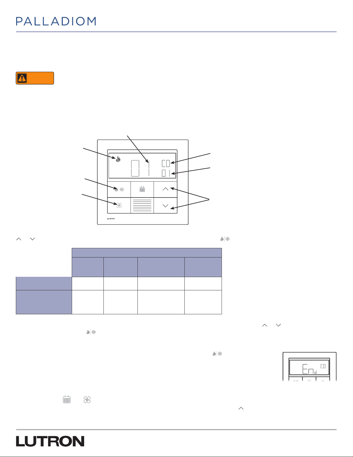
Figure 3: Display on Thermostat in HVAC Controller selection mode
Parameter value
Equipment type configuration
(if two equipment types).
Set
Press to select current value
and proceed to next parameter.
Press to go back to previous
step.
CO = HVAC controller
selection mode
Parameter ID
Press to change parameter value
2. Select value for parameter ID “01”: Select the HVAC controller connected to the thermostat. Using the table below, press
or to select the correct option for the HVAC controller being used and press .
Values based on HVAC controller
Parameter ID 01:
HVAC controller option
Parameter ID 02:
Modbus address
SMC55-RESI
01 02 03 04
01-02*
Mitsubishi
A1M
01-31
(set by DIP
switches
1-5 )*
Cool Automation
CoolPlug
99*
LG
PDRYCB500
01-08
(set by DIP
switches 1-4)*
3. Select value for parameter ID “02”: Select the Modbus address.* Using the table above, press or to select the desired
Modbus address and press .
* For information see instructions included with the controller.
4. Exit HVAC controller selection mode. When “End” is shown, press and hold until the backlight
flashes (3seconds).
Note: “E1” will show on the display if the thermostat is not able to communicate with the HVAC controller.
See the Troubleshooting section on page 30.
Note: If a new HVAC controller is connected to the thermostat, the HVAC controller selection mode will
need to be re-entered. To re-enter the controller selection menu follow the steps below.
a. Press and hold
b. For controller selection mode - Release the buttons and immediately press and hold
and until the backlight flashes (3 seconds).
until the backlight stops flashing and
“CO” is shown (3 seconds).
1
Included with HomeWorks Palladiom Thermostat version 1.10 or newer.
8
Page 9
P/N 032498h
Step 4: Set the SMC55-HWQS Basic Parameters for System Compatibility
This section explains the basic configuration parameters for the SMC55-HWQS. Basic parameters are the critical parameters
which must be configured to control the HVAC equipment. The thermostat will not begin normal operation until these parameters
are configured.
WARNING
If a thermostat is connected to an SMC55-HWQS that has not yet been configured, the thermostat will automatically enter Basic
Configuration Mode. If it is desired to enter Basic Configuration Mode manually, follow the steps below.
1. Cycle power to the thermostat. The remaining 2 steps need to be completed within 15 minutes. If not, repeat Step 1.
2. Press and hold and for 3 seconds until the button backlight is lit and the display flashes.
3. Release the buttons and immediately (with in 15 seconds) press and hold for 3 seconds until the button backlight stops
flashing.
The display on the thermostat will be as shown in Figure 4:
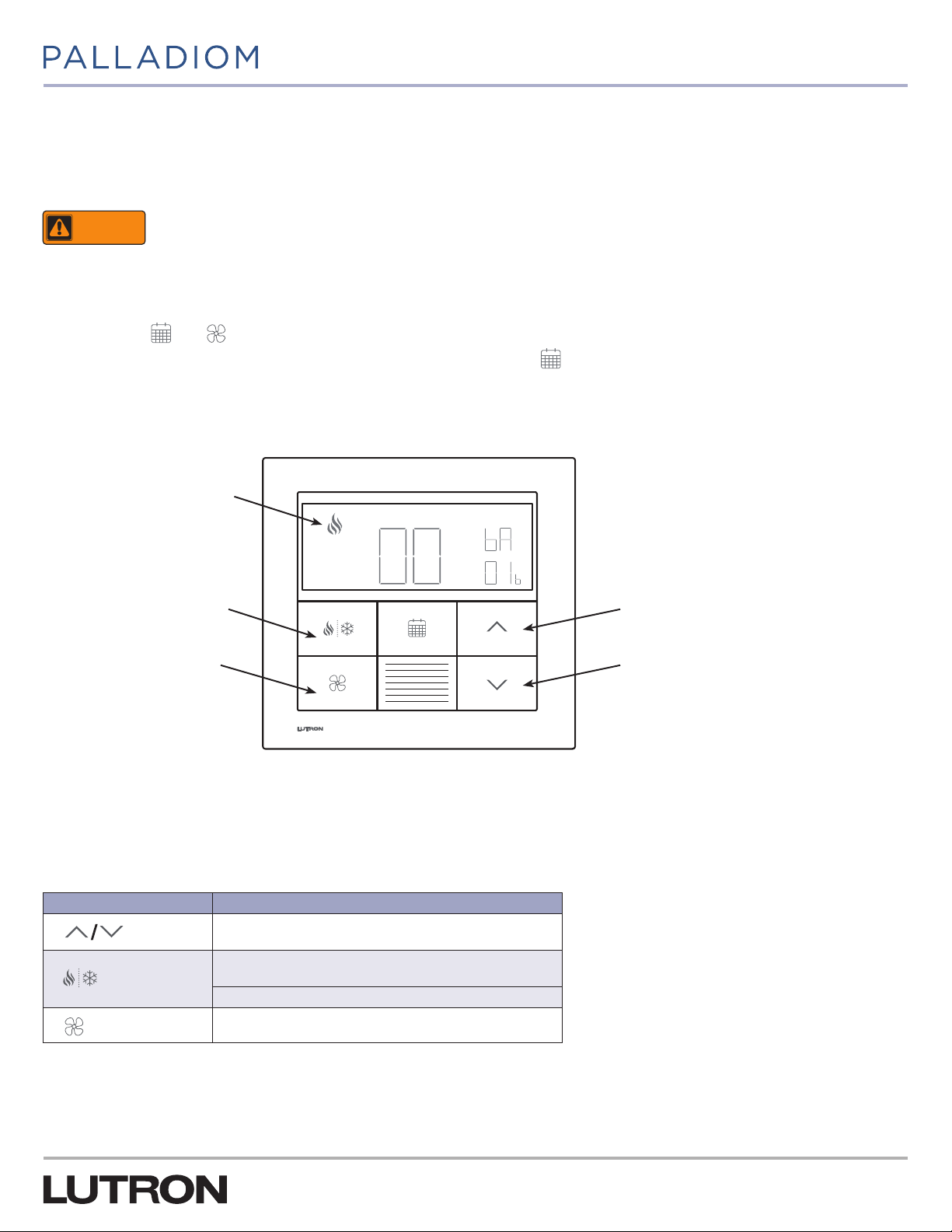
Figure 4: Display on Thermostat in Basic Configuration Mode
Equipment type configuration
(if two equipment types).
Shock Hazard. Improper configuration can cause property damage, personal injury, or death. Installation and
service must be performed by a licensed professional HVAC installer (or the equivalent) or service agency.
Set
Save current parameter value
and go to next parameter
Return to previous parmeter
Increase current parameter value
Decrease current parameter value
In Figure 4, ‘01b’ represents the basic configuration parameter for SMC55-HWQS. ‘00’ represents the value of this parameter
and ‘bA’ indicates that this is a basic parameter.
The following table describes the buttons that are used to select a value of the basic configuration parameter for configuring the
SMC55-HWQS.
Table 2: Buttons Used for Configuring Basic Configuration Parameters
Thermostat Buttons Action
Press to increase/decrease the value of the basic
configuration parameter being displayed on the thermostat.
Press to save the value and go to the next applicable basic
configuration parameter.
Press and hold to exit the ‘End’ screen
Continued on next page...
Press to go back to the previous parameter.
9
Page 10
P/N 032498h
Step 4: Set the SMC55-HWQS Basic Parameters for System
Compatibility (continued)
Verify the wiring connections between the thermostat, the SMC55-HWQS, and HVAC equipment as shown in Figure 1 before
starting to configure the SMC55-HWQS. Table 3 below lists the details of all the basic configuration parameters - applicable
systems, basic configuration parameter index, description, default value, and the range of values for each parameter. For the
HVAC system to function properly these parameters must be configured correctly.
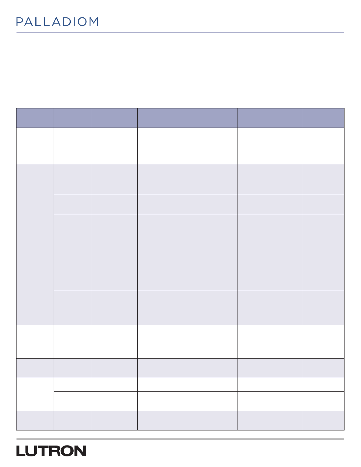
Table 3: Basic Configuration Parameters
Applicable
Systems
All 01b Sys tem Ty pe
Heat
Pump and
Conventional
Basic
Configuration
Parameter
02b Heat Stages
03b
04b
Name Description Default Value Range
Run Auxiliary Heat
) with
(Aux/W
2
other heat stages
Auxiliary Heat
) upstage
(Aux/W
2
delay
00: Conventional system
01: Heat pump
02: 2-Pipe FCU
03: 4-Pipe FCU
04: Underfloor radiant heat
05: Underfloor electric heat
00: None (No Heat Stage)
01: 1 Stage ( W
02: 2 Stage: 1 Compressor and 1 Auxiliar y
03: 2 Stage: 2 Compressor, No Auxiliary
04: 3 Stage: 2 Compressor and 1 Auxiliar y
00: No
01: Ye s
Skipped if no Aux/W
00: 0 minutes
01: 1 minute
02: 2 minutes
03: 5 minutes
04: 10 minutes
05: 20 minutes
06: 30 minutes
07: 1 hour
08: 2 hours
09: 4 hours
10: 8 hours
11- 24 : 11- 24 hour s
Skipped if no Aux/W
)
1
2
2
00: Conventional system 00–05
01: 1 Stage ( W1) 00–04
01: Yes 00–01
05: 20 minutes 00 –24
05b Cool Stages
Conventional 06b Heat Fan Control
Heat Pump 07b
Fan Coil Units
and Radiant
Floor
Fan Coil Units
Radiant Floor 11b Floor Control Type
08b
09b Fa n Type
10b 2-pipe Mode
Change over /
Reversing Valve
(O/B)
Valve / Eleme nt
Type
Continued on next page...
00: None (no cool stage)
01: 1 Cool stage ( Y1)
02: 2 Cool stages (Y1, Y2)
00: Equipment controls fan
01: Thermostat controls fan
00: On for cooling (O)
01: On for heating (B)
00: Relay
01: 0–10 V02: Floating point (Fan coil units only)
00: Relay (G1, G2, G3)
01: 0–10 V-
01: Heat only
02: Cool only
03: Changeover
01: Indoor air only
02: Indoor air and floor limiting
03: Floor temperature only
10
01: 1 Cool stage (Y1) 00–02
01: Thermostat controls fan
00–01
00: On for cooling (O)
00: Relay 00–01
00: Relay (G1, G2, G3) 00–01
03: Changeover 01–03
01: Indoor air only 01–03
Page 11

P/N 032498h
Step 4: Set the SMC55-HWQS Basic Parameters for System
Compatibility (continued)
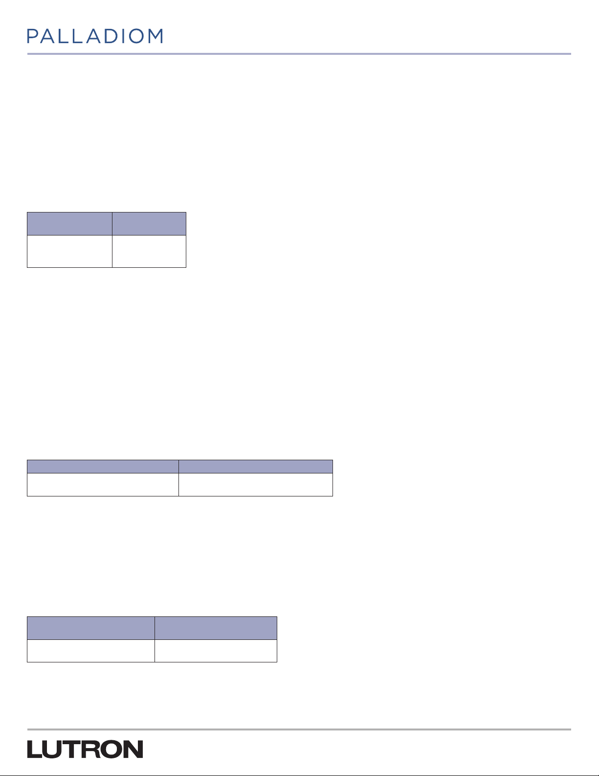
The different basic configuration parameters and the values available for each of these parameters are listed below:
(01b): System Type
Use this parameter to select the HVAC system type. Refer to the HVAC equipment manual or label to identify the type of HVAC
equipment. The different options available for this parameter are listed in the table below:
Table 4: Values for Different Types of HVAC Equipment
Available Options Default Value
00: Conventional
01: Heat pump
02: 2-pipe FCU
03: 4-pipe FCU
04: Hydronic underfloor heating
05: Electric underfloor heating
(02b): Heat Stages
Applicable systems: Conventional and Heat Pump.
Use this parameter to set the number of supported heat stages. This parameter will be skipped if you select an option anything
other than ‘00: Conventional’ or ‘01: Heat Pump’ for the previous parameter (01b). Refer to the HVAC equipment installation
manual or label for the number of supported heat stages. The different options available for this parameter are listed in the table
below:
00: Conventional
Table 5: Values for Different Heat Stages Based on System Type
System type (01b) Values for heat Stages (02b) Default Value
00: Conventional
01: Heat pump
00: No heat stage
01: 1 heat stage ( W
02: 1 primary source and 1 auxiliary source (W2)
00: No heat stage
01: 1 stage (W
02: 2 stage (1 compressor and 1 auxiliary)
03: 2 stage (2 compressors and no auxiliary)
04: 3 stage (2 compressors and 1 auxiliary
)
1
)
1
01: 1 heat stage ( W1)
02: 2 stage (1 compressor
and 1 auxiliary)
Continued on next page...
11
Page 12

P/N 032498h
Step 4: Set the SMC55-HWQS Basic Parameters for System
Compatibility (continued)
(03b): Run Auxiliary Heat (Aux / W2) With Other Heat Stages 1
Applicable Systems: Conventional and Heat Pump only if auxiliary heat stage is supported by the system.
Use this parameter to select whether or not the auxiliary heating stage can be allowed to run along with the other heat stages.
This parameter will be skipped if you select an option anything other than ‘02: 2 stages’ (1 Compressor and
1 Auxiliary/1 Primary source and 1 Auxiliary source [W2]) or ‘04: 3 stage’ (2 Compressor and 1 Auxiliary) for the previous
parameter (02b).
Note for Heat Pump: If auxiliary heat stage runs on gas/oil then it is recommended to choose a value 00: Do not run auxiliary
with other heat stages. Refer to the HVAC equipment manual to determine which value to select.
The different options available for this parameter are listed in the table below:
Table 6: Values for Running Auxiliary Heat With Other Heat Stages
Run Aux/W2 With Other Heat Stages (03b) Default Value of 03b
00: do not run auxiliary with other heat stages
01: Run auxiliary with other heat stages
(04b): Auxiliary Heat (Aux/W2) Upstage Delay 1
01: Run auxiliary with other heat
stages
Applicable systems: Conventional and Heat Pump only if an auxiliary heat stage is supported.
Use this parameter to select the delay between starting the first heat stage and starting the auxiliary heating stage. This
parameter will be skipped if you select a system without auxiliary heat
The different options available for this parameter are listed in the table below:
Table 7: Values for Upstage Auxiliary Delay
Auxiliary Heat (Aux/W2)
Upstage Delay (04b)
00: 0 minutes
01: 1 minute
02: 2 minutes
03: 5 minutes
04: 10 minutes
05: 20 minutes
06: 30 minutes
07: 1 hour
08: 2 hours
09: 4 hours
10: 8 hours
11- 24 : 11- 24 hour s
Default Value
of 04b
05: 20 minutes
1
Included with SMC55-HWQS version 7420 or newer, SMC55-RESI version 7302 or newer and HomeWorks Palladiom Thermostat version 1.10 or newer.
Continued on next page...
12
Page 13
P/N 032498h
Step 4: Set the SMC55-HWQS Basic Parameters for System
Compatibility (continued)
(05b): Cool Stages
Applicable Systems: Conventional and Heat Pump.
Use this parameter to select the number of cool stages. This parameter will be skipped in the menu if you select any option other
than ‘00: Conventional’ or ‘01: Heat Pump’ for the previous parameter (01b). Refer to your HVAC equipment installation manual or
label for the number of supported cool stages. The different options available for this parameter are listed in the table below:
Table 8: Values for Cooling Stages
Values for Cooling
Stages in 05b
00: None
01: 1 stage
02: 2 stage
Refer to Table 21 in Appendix A for the details about the different relays that get energized in the different cool stages for Heat
Pump and Conventional systems.
(06b): Heat Fan Control
Applicable System: Conventional systems with at least one heat stage.
Default Value
01: 1 stage
Use this parameter to specify if the SMC55-HWQS should turn on the fan when turning on the heat. For some HVAC system
types, a control signal for the fan is not needed from the SMC55-HWQS because the equipment automatically turns the fan
on when there is a call for heat. In such cases ensure that AUTO is enabled in the available Fan Modes in the HomeWorks QS
designer software.
This parameter will be skipped and will default to have the fan turn on with the heating if you select a system type that is not
conventional or has no heating stages. Refer to your HVAC equipment manual and HVAC equipment label to identify the type of
conventional system. The different options available for this parameter are listed in the table below:
Table 9: Values for Heat Fan Type
Values for 07b Default Value
00: Equipment controls the fan relay
01: Thermostat controls the fan relay
01: Thermostat controls the fan relay
(07b): Changeover/Reversing Valve (O/B) Type 1
Applicable System: Heat Pump.
Use this parameter to select the type of reversing valve: energize for heating or energize for cooling. This parameter will be
skipped in the menu if you select any option other than ‘01: Heat Pump’ for the previous parameter (01b). Refer to your HVAC
equipment manual to identify the type of reversing valve (O/B). The different options available for this parameter are listed in the
table below:
Table 10: Values for Different Types of Reversing Valves
Changeover/Reversing Valve
(O/B) Type (07b)
00: Energize for cooling (O)
01: Energize for heating (B)
Default Value
00: Energize for cooling (O)
1
Included with SMC55-HWQS version 7420 or newer, SMC55-RESI version 7302 or newer and HomeWorks Palladiom Thermostat version 1.10 or newer.
Continued on next page...
13
Page 14

P/N 032498h
Step 4: Set the SMC55-HWQS Basic Parameters for System
Compatibility (continued)
(08b): Valve / Element Type
Applicable Systems: Fan Coil Units and Radiant Underfloor heating.
Use this parameter to select the type of valve control for heating and cooling. The heating and cooling valves can either have a
relay control (two position On / Off) or a proportional control (0–10 V-). This parameter will be skipped in the menu if you select
any option other than ‘02: 2-pipe FCU’, ‘03: 4-pipe FCU’ or ‘04: Radiant Underfloor Heating’ for the previous parameter (01b).
Refer to your HVAC equipment manual to identify the type of valve control supported by your HVAC equipment. The different
options available for this parameter are listed in the table below:
Table 11: Values for Type of Valve Control
Valve / Eleme nt Type (08b) Default Value
00: Relay
01: 0–10 V02: Floating point (FCUs only)
(09b): Fan Type
Applicable System: Fan Coil Units.
Use this parameter to select the type of control for fan. The fan can have either a relay control (3-speed fan control) or a
proportional control (0–10 V-).
1
00: Relay
Note: Some of the Fan Coil Units can have a two-pole contact closure with a 2-speed fan (medium and high) or a single speed
fan (low). Refer to the wiring diagram in thermostat installation guide to install the SMC55-HWQS with Fan Coil Units with a
2-speed or single-speed fan.
This parameter will be skipped in the menu if you select any option other than ‘02: 2-pipe FCU’ or ‘03: 4-pipe FCU’ for the
previous parameter (01b). Refer to HVAC equipment manual to identify the type of fan control supported by your HVAC
equipment. The different options available for this parameter are listed in the table below:
Table 12: Values for Type of Fan Control
Fan Type (09b) Default Value
00: Relay 3-speed fan
01: 0–10 V- continuous speed
00: Relay 3-speed fan
1
For floating point control, see Application Note #630. Basic Configuration set for the valve type is overridden when selecting Floating Point.
Continued on next page...
14
Page 15

P/N 032498h
Step 4: Set the SMC55-HWQS Basic Parameters for System
Compatibility (continued)
(10b): 2-Pipe Mode
Applicable System: 2-pipe Fan Coil Units.
Use this parameter to select the type of 2-pipe mode. Heat only mode is used only for heating, Cool only mode is used only
for cooling. Changeover mode is used to either heat or cool depending on the temperature of the water in the pipes. In the
changeover mode, a changeover sensor must be connected to the SMC55-HWQS. Refer to the Thermostat installation guide to
install the changeover sensor.
When the water temperature is above the value selected for the advanced parameter ‘ChangeOverToHeatTemperature’,
the SMC55-HWQS switches to the heating mode. It stays in the heating mode until the water temperature falls below the
value selected for the advanced parameter ‘ChangeOverToCoolTemperature’. When the water temperature is below the
value selected for the advanced parameter ‘ChangeOverToCoolTemperature’, the SMC55-HWQS changes over to cooling
mode. It stays in the cooling mode until the water temperature rises above the value selected for the advanced parameter
‘ChangeOverToHeatTemperature’.
If the water temperature is between the two changeover points immediately after power up, the operating mode starts in the
previous mode as per the value in the advanced parameter ‘2PipePreviousOperatingMode’. The water temperature is measured
at 30 second intervals and the operating mode is updated accordingly.
This parameter will be skipped in the menu if you select any option other than 02: 2-Pipe for the previous parameter (01b). Refer
to HVAC equipment manual to identify the type of 2-pipe FCU. The different options available for this parameter are listed in the
table below:
Table 13: Values for 2-pipe Mode
2-Pipe Mode (10b) Default Value
01: Heat only
02: Cool only
03: Changeover
03: Changeover
Continued on next page...
15
Page 16

P/N 032498h
Step 4: Set the SMC55-HWQS Basic Parameters for System
Compatibility (continued)
(11b): Underfloor Heating Control 1
Applicable Systems: Radiant Underfloor heating.
Use this parameter to select the type of control for radiant underfloor heating systems. Radiant underfloor heating systems can
be controlled in three ways:
1. Based on indoor air temperature – This type of control is used to control the temperature depending on the room air
temperature.
2. Based on floor temperature sensor – This type of control is used to control the temperature depending on the temperature
measured by the floor temperature sensor.
3. Based on indoor air and floor limiting – This control type is similar to option ‘01: Indoor air temperature’. The air temperature is
controlled with the added feature to always maintain the temperature of the floor between the Slab Minimum and Slab Maximum
temperatures. This parameter will be skipped if you select any option other than ‘04: Radiant Underfloor Heating’ for the previous
parameter (01b). The different options available for this parameter are listed in the table below:
Table 14: Values for Underfloor Control
Underfloor Heating Control (11b) Default Value
01: Indoor air temperature
02: Indoor air and floor limiting
03: Floor temperature sensor only
01: Indoor air
temperature
Note: Refer to the installation manual of the underfloor heating equipment to install the floor sensor if the control type selected is
‘02: Indoor Air and Floor Limiting’ or ‘03: Floor Temperature Sensor’ only.
1
Included with SMC55-HWQS version 7420 or newer and HomeWorks Palladiom Thermostat version 1.10 or newer.
Continued on next page...
16
Page 17

Step 4: Set the SMC55-HWQS Basic Parameters for System
Compatibility (continued)
Saving and Exiting Basic Configuration
Once the values for all the applicable basic configuration parameters are entered, the following will be displayed on the
thermostat.
Figure 5: End Screen for Basic Configuration Parmeters
Press and hold to save all
parameters to SMC55-HWQS
and exit to normal operation
Return to previous parameter
P/N 032498h
The display in Figure 5 indicates that all the parameters specific to the HVAC system type are selected. At this stage, it is
recommended to verify the values selected for each parameter. To verify the values selected for each parameter press the
button. Keep pressing the button until the values of all the parameters is verified. Once all the values are verified, press the
button till you enter the ‘End’ screen.
When in the ‘End’ screen, press and hold the button until the button backlights flash and the display shows the current
room temperature (3 seconds) or the HVAC controller selection mode for the second zone (depending on the equipment
configuration). This is the normal operating mode and the thermostat and the SMC55-HWQS will start controlling the HVAC
equipment. Refer to Figure 6 for an example of the display in normal operating mode.
Figure 6: Normal Operating Mode of the Thermostat
On
AUTO
Auto
Set
Set
17
Page 18

P/N 032498h
Step 5: Set the SMC55-HWQS Advanced Parameters to Modify the
Functionality of the HVAC System
Use the Advanced Configuration Mode if any advanced configuration parameters must change from their default value.
To change / modify the advanced parameters, follow the steps below.
1. Press and hold and for 3 seconds until the buttons backlight and the display flashes.
2. Release the buttons and immediately (with in 15 seconds) press and hold for 3 seconds until the button backlights stop
flashing. Advanced configuration parameter ‘01A’ will be shown.
The display on the thermostat will be as shown in Figure 7.
Figure 7: Advanced Configuration Mode
Flashes while editing the value
of the selected parameter
Flashes while selecting the
Set
Tap to save parameter value
Hold to save all settings and
exit mode
parameter ID to edit
Increase current parameter value
Returns to selecting the
parameters without saving
the current value
Decrease current parameter value
In Figure 7, 01A represents the advanced configuration parameter for SMC55-HWQS. ‘00’ represents the value of this parameter
and ‘Ad’ indicates that this is an advanced configuration parameter. The following table describes the buttons that are used to
select a value for the advanced configuration parameter to configure the SMC55-HWQS.
Table 15: Buttons Used to Select Advanced Configuration Parameters
Thermostat Buttons Action
Press to select the advanced parameter or the value of the advanced
configuration parameter. Either the advanced parameter or value of the
advanced parameter will flash on pressing the button.
Press and hold to exit the Advanced Configuration Mode.
Press to increase / decrease the advanced parameter or value of the
advanced parameter, whichever is flashing in the menu.
Press to go back to previous parameter.
Continued on next page...
18
Page 19

P/N 032498h
Step 5: Set the SMC55-HWQS Advanced Parameters to Modify the
Functionality of the HVAC System (continued)
Table 16 lists out the details of all the advanced configuration parameters. Some of the advanced parameters are applicable to
all types of HVAC equipment while some are applicable to a specific type of HVAC equipment. The table below also categorizes
these parameters based on the type of applicable systems.
Table 16: Advanced Configuration Parameters for the SMC55-HWQS
Applicable
Systems
All
All
(except
for radiant
underfloor
heat)
All
FCUs with
multi-speed
fan
Advanced
Configuration
Parameter
01A Function Type
02A
03A Deadband Inactive range above and below the Setpoint 1 °F 0.1 °F – 10 °F
06A
07A
08A
11A Cool Fan on Delay
12A Heat Fan on Delay
18A
19A
20A
26A
27A
05A
09A
Name Description Default Value Range
2: Not Configured
(sets itself to 0
automatically when
connected to a
thermostat and basic
configuration is entered)
1: Thermostat sensor 0 – 1
0 seconds 0 – 99
0 seconds 0 – 99
3: Auto 0 – 3
4: Au to 0 – 5
0° F -5.0 – +5.0
30 minutes 0.5 – 99.5
0: Alarm and keep trying 0 – 1
1.5 °F 0.1 – 10.0
0: Off 0 – 1
0 – 2
0 – 99.9
(minutes)
0 – 99.9
(minutes)
Temperature
Se n s or Ty p e
Minimum Fan
On Time
Overrun Cool
Fan Time
Overrun Heat Fan
Time
Standalone
Temperature
Operation Mode
Standalone Fan
Mode
(not applicable to
radiant floors)
Remote Sensor
Temperature
Offset
Cannot Reach
Setpoint Timeout
Cannot Reach
Setpoint Action
Fan High
Differential
Kick-Star t Fan
(multi-speed
fan only)
0: Operate with thermostat
1: Standalone
2: Not Configured
0: Flush mounted sensor connected to
HVAC controller
1: Thermostat sensor
Minimum time fan is on in auto mode (minutes) 2 minutes 0 – 99
Minutes the fan runs after cooling relay opens 0 minutes
Minutes the fan runs after heating relay opens 0.1 minutes
Time to delay start of fan after cooling star ts.
Only used with Fan Auto Speed when fan was
las t of f.
Time to delay start of fan after heating starts.
Only used with Fan Auto Speed when fan was
las t of f.
0: Off
1: Heat Only
2: Cool Only
3: Auto
0: Off
1: L ow
2: Medium
3: High
4: Au to
5: Single Speed On
Temperature offset for remote temperature
sensor. This allows for compensation based
on the installation location of the probe.
Cannot reach setpoint alarm time threshold
(minutes)
0: Alarm and keep trying
1: Alarm and enter failsafe
Auto fan mode temperature difference in
degrees to switch from medium to high fan
speed
0: Off
1: Set fan high for 1 second when turning on
Continued on next page...
19
Page 20

Step 5: Set the SMC55-HWQS Advanced Parameters to Modify the
Functionality of the HVAC System (continued)
Table 16: Advanced Configuration Parameters for the SMC55-HWQS (continued)
1
Advanced
Configuration
Parameter
40A
41A
42A
43A
44A
50A
51A
52A
53A
54A
55A
56A
60A
61A
70A
71A
72A
74A
75A
76A
77A
Name Description Default Value Range
Pipe Temperature
for Changeover to
Heat Mode
Pipe Temperature
for Changeover to
Cool Mode
Enable Purge
Function
Purge Valve
On-Time
Purge Valve
Off-T ime
Proportional Fan
Minimum
Proportional Fan
Low Speed
Proportional Fan
Medium Speed
Proportional Fan
High Speed
Minimum Valve
Percent Open
Valve Fully Open
Differential
Non-proportional
Analog output
Enable Floating
Point
Actuator Running
Time
Minimum
Compressor Run
Time (MCRT)
Minimum
Compressor Off
Time (MCOT)
Heat stage 1 delay
(WOD)
Heat Stage 1
) On
(Y
1/W1
Heat Stage 1
(Y1 / W1) Off
Heat Compressor
Stage 2 (Y2) On
Heat Compressor
Stage 2 (Y2) Off
Pipe temperature that designates heating
mode when using a 2-pipe system with a
changeover sensor on the pipe.
Pipe temperature that designates heating
mode when using a 2-pipe system with a
changeover sensor on the pipe.
Turns the valve on if left dormant to refresh
pipe temperature; 0: Disabled; 1: Enabled
Number of minutes to leave the valve on during
a purge. 0: Disabled
Hours to leave the valve off between purges
0: Disabled
The lowest percent output to apply for fan
speed. This determines the low end-point of
the fan being on. If at any time the fan output is
0% (Off), the valves will also close at 0%.
The % output to apply when the manual fanspeed is set to Medium.
The % output to apply when the manual fanspeed is set to Medium.
The % output to apply when the manual fanspeed is set to High.
The lowest % output to apply for valve
opening. This determines the low end-point of
the straight-line curve for valve opening.
The temperature offset from deadband at
which the valve is fully open (100% opening).
Enable 0–10 V- outputs for non-proportional
fan and valves.
0: Disabled, 1: Enabled (overrides basic valve
configuration)
Actuator Running Time for Floating Point
control.
Minimum run time for compressor. 0 minutes 0 – 99 minutes
Minimum off time for compressor. 5 minutes 0 – 99 minutes
Minimum off time for W1 (conventional heat
stage 1)
°F below setpoint to turn stage on. 1 °F
°F above setpoint to turn stage off. 1 °F
°F below setpoint to turn stage on. 2 °F
°F above setpoint to turn stage off. 0 °F
82 °F 75 – 99
60 °F 32 – 70
1: Enabled 0 – 1
2 minutes 0 – 60
2 hours
10% 0 – 100
20% 0 – 100
60% 0 – 100
100% 0 – 100
10% 0 – 100
1 °F .1 – 10.0
True (1)
0: Disabled 0 – 1
150 seconds 1 – 999
3 minutes 0 – 99 minutes
0.5 – 99.5
(hours)
0: disabled
1: enabled
1 °F – 10 °F
1 °F – 10 °F
1 °F – 10 °F
1 °F – 10 °F
Applicable
Systems
2-pi pe FCU
0–10 V- FCU
Floating Point
Valves
Heat
1
and
Pump
Conventional
Heat Pump
P/N 032498h
1
Included with SMC55-HWQS version 7420 or newer, SMC55-RESI version 7302 or newer and HomeWorks Palladiom Thermostat version 1.10 or newer.
Continued on next page...
20
Page 21

Step 5: Set the SMC55-HWQS Advanced Parameters to Modify the
Functionality of the HVAC System (continued)
Table 16: Advanced Configuration Parameters for the SMC55-HWQS (continued)
Applicable
Systems
Heat
1
and
Pump
Conventional
Heat
1
Pump
Radiant
1
Floor
Advanced
Configuration
Parameter
78A Aux / W2 On
79A Aux / W2 Off
80A
81A
82A
83A
84A
85A
88A
90A Slab Maximum
91A Slab Minimum
92A
93A
94A
Name Description Default Value Range
Cool Stage 1 On
Cool Stage 1 Off
Cool Stage 2 On
Cool Stage 2 Off
Compressor
Cool Stage 2
Upstage Delay
Compressor
Heat Stage 2
Upstage Delay
Reversing
Valve Delay
(RVD)
Floor 100%
Differential
Temperature
Floor 0%
Differential
Temperature
Cycles Per Hour
°F below setpoint to turn stage on. If auxiliary is stage 2, this
differential is used to turn on.
°F above setpoint to turn stage off. If auxiliary is stage 2, this
differential is used to turn off.
°F above setpoint to turn stage on. 1 °F
°F below setpoint to turn stage off. 1 °F
°F above setpoint to turn stage on. 2 °F
°F below setpoint to turn stage off. 0 °F
Stage 2 cooling will not turn on until the first stage has run
for the chosen duration.
0: 0 minutes, 1: 1 minute, 2: 2 minutes, 3: 5 minutes,
4: 10 minutes, 5: 20 minutes, 6: 30 minutes, 7: 1 hour,
8: 2 hours, 9: 4 hours, 10: 8 hours, 11–99: 11–99 hours
Stage 2 compressor heating will not turn on until the first
stage has run for the chosen duration.
0: 0 minutes, 1: 1 minute, 2: 2 minutes, 3: 5 minutes,
4: 10 minutes, 5: 20 minutes, 6: 30 minutes, 7: 1 hour,
8: 2 hours, 9: 4 hours, 10: 8 hours, 11–99: 11–99 hours
Delay to wait for reversing valve to change over. When changing
between heat and cool, the thermostat will turn off the
compressor, then wait for MCOT. The thermostat will then change
the state of the O/B signal, and wait for the reversing valve delay
(RVD) before turning the compressor and fan back on.
If slab temperature rises above this maximum, must turn off
regardless of air temperature.
If slab temperature falls below this minimum, must turn on
regardless of air temperature.
°F below the setpoint to turn on system to 100%. 2.0 °F 0 – 20 °F
°F above the setpoint to turn on system to 0%. 2.0 °F 0 – 20 °F
Cycles per hour (CPH).
3 °F
0 °F
0 minutes
0 minutes, however
thermostat will default
based on stages
1 second
85 °F 0 – 120 °F
60 °F 0 – 120 °F
3 (20 minute signal period)
P/N 032498h
1 °F – 10 °F
1 °F – 10 °F
1 °F – 10 °F
1 °F – 10 °F
1 °F – 10 °F
1 °F – 10 °F
0 – 99
minutes
0 – 99
minutes
0 – 99
seconds
1-20 CPH
1
Included with SMC55-HWQS version 7420 or newer and HomeWorks Palladiom Thermostat version 1.10 or newer.
Continued on next page...
21
Page 22

P/N 032498h
Step 5: Set the SMC55-HWQS Advanced Parameters to Modify the
Functionality of the HVAC System (continued)
Parameters Applicable to All Types of HVAC Equipment
Some of the advanced configuration parameters are applicable to all types of HVAC equipment. This sections lists out the details
about these parameters.
(01A) Function Type
Use this parameter to define if the SMC55-HWQS is configured to work with the thermostat or configured to work as a
standalone device without the thermostat. The SMC55-HWQS can work as a standalone HVAC controller if a remote air sensor
is connected to the SMC55-HWQS. The default value for this parameter is set as ‘02: Not Configured’. Saving and exiting the
basic configurations mode will automatically set this parameter to ‘00: Operate with Thermostat’ by default.
This parameter can be set to ‘01’ to still function without the thermostat connected. Once the thermostat is connected, you must
change the value of this parameter back to ‘00’ so that the SMC55-HWQS should work with the thermostat.
Note: Standalone mode (‘01’) requires connecting a wired remote air temperature sensor to the SMC55-HWQS. See the
SMC55-HWQS instruction sheet included in the box with the remote air temperature sensor. Set the parameter ‘02A’ to ‘00:
Remote Temperature Sensor’ so that SMC55-HWQS can work with the remote sensor.
(02A) Temperature Sensor Type
Use this parameter to identify the temperature sensor used to measure the room temperature. Set this parameter to ‘01’ if using
the sensor inside the thermostat to measure the room temperature. Set this parameter to ‘00’ if using the remote temperature
sensor to measure the room temperature.
(06A) Minimum Fan On Time
Use this parameter to identify the minimum time the fan will run once it has turned on irrespective of whether or not the system is
running. This minimum run time is used to avoid short cycling the fan motor.
(07A) Extended Cool Fan Time (OCFT)
Use this parameter to identify the extended amount of time which the fan runs after the system stops cooling. This is used to
purge the cool air out of the vents.
(08A) Extended Heat Fan Time (OHFT)
Use this parameter to identify the extended amount of time which the fan runs after the system stops heating. This is used to
purge the hot air out of the vents.
(11A) Cool Fan On Delay (CFOD)
Use this parameter to identify the time delay before the fan turns on after the system starts cooling. This is used so that
uncomfortably hot air is not blown out of the vents.
(12A) Heat Fan On Delay (HFOD)
Use this parameter to identify the time delay before the fan turns on after the system starts heating. This is used so that
uncomfortably cold air is not blown out of the vents.
(18A) Standalone Temperature Operation Mode
Use this parameter to identify the operating mode when the SMC55-RESI is set up to work in a standalone mode without the
thermostat.
(19A) Standalone Temperature Fan Mode
Use this parameter to identify the fan mode when the SMC55-RESI is set up to work in a standalone mode without the thermostat.
Continued on next page...
22
Page 23

P/N 032498h
Step 5: Set the SMC55-HWQS Advanced Parameters to Modify the
Functionality of the HVAC System (continued)
Parameters Applicable to All Types of HVAC Equipment (continued)
(26A) Cannot Reach Setpoint Timeout
Use this parameter to identify the maximum time it should take to reach the desired setpoint. If the desired setpoint is not
reached within this time then an alarm is triggered to notify the user.
(27A) Cannot Reach Setpoint Action
Use this parameter to identify whether or not the system should continue heating or cooling after the alarm for ‘Cannot Reach
Setpoint’ is triggered.
Set this parameter to ‘00’ if the system should continue heating/cooling. Set this parameter to ‘01’ if the system should stop
heating or cooling when ‘Cannot Reach Setpoint’ alarm is triggered.
Parameters Applicable to Conventional and Heat Pump Systems
This section lists out the details of the advanced configuration parameters applicable to Conventional and Heat Pump systems.
(70A) Minimum Compressor Run Time (MCRT)
Use this parameter to identify the minimum time the compressor must run to ensure proper lubrication. Refer to Figure 8 b elow.
Even though the desired temperature setpoint is met the compressor will run for an additional amount of time till the minimum
compressor run time expires.
Figure 8: Compressor Runs Until Minimum Compressor Time Expires
Min Compressor Run Time
Call Input for Compressor
Y
- Compressor
1
signal out
Call for no
compressor
MCRT = 1 minute MCRT = 1 minute
MCRT Starts MCRT Starts
Time
Call for no
compressor
(71A) Minimum Compressor Off Time (MCOT)
Use this parameter to identify the minimum time for which the compressor must remain Off before it can start. This delay is
intended to reduce compressor restart stress. Fan will stay off in Auto mode during this delay. Refer to the Figure 9 below, the
compressor will start only after MCOT has expired.
Figure 9: Minimum Time for Which The Compressor Must Remain Off Before It Can Start
Min Compressor Off Time
Call Input for Compressor
Y1 - Compressor
signal out
Call for no compressor,
MCOT Start
MCOT = 5 minute MCOT = 5 minute
Call for no compressor,
MCOT Start
G - Fan output signal
Continued on next page...
Time
23
Page 24

P/N 032498h
Step 5: Set the SMC55-HWQS Advanced Parameters to Modify the
Functionality of the HVAC System (continued)
Parameters Applicable to Conventional and Heat Pump Systems (continued)
(74A) Heat Stage 1 – On Del ta 1
Use this parameter to identify the temperature below the heat setpoint when Heat Stage 1 should turn on. Refer to the control
diagrams in Appendix A. These diagrams graphically represent the Heat Stage 1-On Delta for Conventional and Heat Pump
systems.
(75A) Heat Stage 1 – Off Delta 1
Use this parameter to identify the temperature above the heat setpoint when Heat Stage 1 should turn off. Refer to the control
diagrams in Appendix A. These diagrams graphically represent the Heat Stage 1-Off Delta for Conventional and Heat Pump
systems.
(76A) Heat Stage 2 (Y2/W2/Aux) – On Delta 1
Use this parameter to identify the temperature below the heat setpoint when Heat Stage 2 should turn on. Refer to the control
diagrams in Appendix A. These diagrams graphically represent the Heat Stage 2-On Delta for Conventional and Heat Pump
systems.
(77A) Heat Stage 2 – Off Delta 1
Use this parameter to identify the temperature above the heat setpoint when Heat Stage 2 should turn off. Refer to the control
diagrams in Appendix A. These diagrams graphically represent the Heat Stage 2-Off Delta for Conventional and Heat Pump
systems.
(78A) Heat Stage 3 (Aux) – On Del ta 1
Use this parameter to identify the temperature below the heat setpoint when Heat Stage 3 (Aux) should turn on. Refer to the
control diagrams in Appendix A. These diagrams graphically represent the Heat Stage 3-On Delta for Conventional and Heat
Pump systems.
(79A) Heat Stage 3 (Aux) – Off Delta 1
Use this parameter to identify the temperature above the heat setpoint when Heat Stage 3 (Aux) should turn off. Refer to the
control diagrams in Appendix A. These diagrams graphically represent the Heat Stage 3-Off Delta for Conventional and Heat
Pump systems.
(80A) Cool Stage 1 – On Delta 1
Use this parameter to identify the temperature above the cool setpoint when Cool Stage 1 should turn on. Refer to the control
diagrams in Appendix A. These diagrams graphically represent the Cool Stage 1-On Delta for Conventional and Heat Pump
systems.
(81A) Cool Stage 1 – Off Delta 1
Use this parameter to identify the temperature below the cool setpoint when Cool Stage 1 should turn off. Refer to the control
diagrams in Appendix A. These diagrams graphically represent the Cool Stage 1-Off Delta for Conventional and Heat Pump
systems.
(82A) Cool Stage 2 – On Del ta 1
Use this parameter to identify the temperature above the cool setpoint when Cool Stage 2 should turn on. Refer to the control
diagrams in Appendix A. These diagrams graphically represent the Cool Stage 2-On Delta for Conventional and Heat Pump
systems.
1
Included with SMC55-HWQS version 7420 or newer, SMC55-RESI version 7302 or newer and HomeWorks Palladiom Thermostat version 1.10 or newer.
Continued on next page...
24
Page 25

P/N 032498h
Step 5: Set the SMC55-HWQS Advanced Parameters to Modify the
Functionality of the HVAC System (continued)
Parameters Applicable to Conventional and Heat Pump Systems (continued)
(83A) Cool Stage 2 – Off Delta 1
Use this parameter to identify the temperature below the cool setpoint when Cool Stage 2 should turn off. Refer to the control
diagrams in Appendix A. These diagrams graphically represent the Cool Stage 2-Off Delta for Conventional and Heat Pump
systems.
(84A) Compressor Cool Stage 2 Upstage Delay (CC2SUD) 1
Use this parameter to identify the time delay after the first stage of cooling has started before the Stage 2 for cooling starts. Refer to
Figure 10 below for the upstage delay before the Stage 2 of cooling is turned on.
Figure 10: Upstage Delay Before Starting Cooling Stage 2
Energizing O/B valve - Enable
cooling
Call Input for Compressor
- Compressor
Y
1
signal out
- Compressor
Y
2
signal out
G - Fan On
Cooling energized
Call for Stage 2 cooling
Upstage 2nd cool
stage delay = 2 min.
FODC
OCFT
FODC
OCFT
(85A) Compressor Heat Stage 2 Upstage Delay (CH2SUD) 1
Use this parameter to identify the time delay after the first stage of heating has started before the Stage 2 of heating starts.
(88A) Reversing Valve Delay (RVD) 1
Applicable System: Heat pump only.
Use this parameter to identify the time delay required for energizing the reversing valve. RVD is used to ensure that the reversing
valve is fully energized before turning on the compressor. This delay is used in the following scenarios:
a. Turning on the SMC55-HWQS.
b. Transitioning from heating to cooling and from cooling to heating (after MCOT expires).
c. Transitioning from operating mode ‘Off’ to operating mode ‘Heating’, ‘Cooling’, or ‘Auto’ (after MCOT expires).
Refer to Figure 11 below, the system will start after both MCOT and RVD have expired.
Figure 11: The Heat Pump Starts Heating/Cooling Only After Reversing Valve Delay Expires
Reversing Valve Delay
Call input for reversing valve
Call input for compressor
MCOT started
O/B - Reversing valve signal out
- Compressor signal out
Y
1
1
Included with SMC55-HWQS version 7420 or newer, SMC55-RESI version 7302 or newer and HomeWorks Palladiom Thermostat version 1.10 or newer.
MCOT (5 min.)
Call for compressor
RVD started
Reversing
Valve Delay
MCOT started
Call for compressor
MCOT (5 min.)
Continued on next page...
25
Page 26

Step 5: Set the SMC55-HWQS Advanced Parameters to Modify the
Functionality of the HVAC System (continued)
P/N 032498h
Parameters Applicable for Radiant Underfloor Heating System
1
Radiant Underfloor Heating Control Summary
Pulse Width Modulation (PWM) Temperature Control (for relay signals only)
Both indoor air temperature control and floor temperature control uses a PWM control algorithm when using relays. PWM works
by turning the heat on during a calculated percentage of the cycles per hour (parameter 94A).
For example, if the controller is configured to have 3 cycles per hour, there will be three 20-minute time periods in an hour. Every
time period will have the heat on for a calculated percentage of the period, known as a “duty cycle”. The duty cycle is calculated
mostly by the temperature difference from the setpoint.
• The duty cycle equals 100% of the time period when the temperature is at or below the setpoint minus the floor 100%
differential (parameter 92A).
Example: If the setpoint equals 70 °F, the duty cycle is 100% when the temperature is at or below 68°F (70 °F − 2 °F).
• The duty cycle equals 0% of the time period when the temperature is at or above the setpoint plus the floor 0% differential
(parameter 93A)
Example: If the setpoint equals 70 °F, the duty cycle is 0% (off) when the temperature is at or above 72 °F (70 °F + 2 °F).
Figure 12: Simplified Graph of the Duty Cycle Calculation
100
90
80
70
60
50
40
30
Duty Cycle On %
20
10
0
60 61 62 63 64 65 66 67 68 69 70 71 72 73 74 75 76 77 78 79 80
Temperature (°F)
Short Cycle Prevention: To prevent the controller from cycling too quickly, duty cycle rounding is used if the cycle is almost fully
on or off. If the duty cycle value is 95% or higher, the duty cycle is rounded to 100%. If the duty cycle value is below the minimum
pulse width (Parameter 54A), the duty cycle is rounded to 0%.
0–10 V- Control (for 0–10 V- signal only)
If the valve control is set to 0–10 V-, the controller provides a continuous voltage output to the valve actuator. Similar to PWM
with relay control, the duty cycle calculated determines the output, but now in a voltage instead of an on / off interval. For
example, a duty cycle of 30% is similar to a 3.0 V output signal to the valve actuator.
Duty Cycle Sample Adaptation (for both relay and 0–10 V- signals)
The radiant floor control algorithm also uses a duty cycle sample adaptation. The purpose of the adaptation is to dynamically
change the duty cycle according to the newly sampled temperature.
1
Included with SMC55-HWQS version 7420 or newer and HomeWorks Palladiom Thermostat version 1.10 or newer.
Continued on next page...
26
Page 27

Step 5: Set the SMC55-HWQS Advanced Parameters to Modify the
Functionality of the HVAC System (continued)
P/N 032498h
Parameters Applicable for Radiant Underfloor Heating System
1
(continued)
Parameter details
(54A) Minimum Pulse Width
The lowest valve on-time allowed. This determines the low-end point of the straight-line curve for valve duty cycle.
(90A) Slab Maximum
This parameter indicates the maximum temperature in Fahrenheit of the radiant floor after which the underfloor heating system
stops heating irrespective of the indoor air temperature.
(91A) Slab Minimum
This parameter indicates the minimum temperature in Fahrenheit of the radiant floor below which the underfloor heating system
starts heating irrespective of the indoor air temperature.
(92A) Floor 100% Differential Temperature
Use this parameter to indicate the temperature in Fahrenheit below the heat setpoint when the underfloor heating system is at
maximum capacity.
(93A) Floor 0% Differential Temperature
Use this parameter to indicate the temperature in Fahrenheit above the heat setpoint when the underfloor heating system is at
minimum capacity.
(94A) Cycles Per Hour (CPH)
Use this parameter to indicate the total number of heating / cooling cycles per hour. For example, setting this parameter to
3cycles per hour indicates a 20 minute cycle.
Parameters Applicable for 0–10 V- Fan Coil Units
This section lists out the details of the advanced configuration parameters applicable to 0–10 V- Fan Coil Units.
(50A) Proportional Fan Minimum
This parameter indicates the minimum percentage output for the fan to turn on. Below this value the fan will remain off.
(51A) Proportional Fan Low Speed
This parameter indicates the percentage output required to set the manual fan speed to ‘Low’.
(52A) Proportional Fan Medium Speed
This parameter indicates the percentage output required to set the manual fan speed to ‘Medium’.
(53A) Proportional Fan High Speed
This parameter indicates the percentage output required to set the manual fan speed to ‘High’.
(54A) Minimum Valve Percent Open
This parameter indicates the minimum percentage of output required to open the valves.
(55A) Valve Fully Open Differential
This parameter indicates the temperature offset from the deadband in Fahrenheit at which the valves are completely open.
(56A) Non-proportional Analog Output
This parameter indicates whether or not the valves follow non-proportional 0–10 V- output. Set this parameter to ‘01’ if enabling
non-proportional analog output for valves. When enabled, only two analog output values are used, 0 V- and 10 V-.
1
Included with SMC55-HWQS version 7420 or newer and HomeWorks Palladiom Thermostat version 1.10 or newer.
Continued on next page...
27
Page 28

P/N 032498h
Step 5: Set the SMC55-HWQS Advanced Parameters to Modify the
Functionality of the HVAC System (continued)
Parameters Applicable for 2-pipe Fan Coil Units
This section lists out the details of the advanced configuration parameters applicable to 2-Pipe Fan Coil Units.
(40A) Change Over to Heat for Pipe Temperature
Use this parameter to indicate the temperature at which the operating mode of a 2-pipe FCU changes to heating. This is
applicable only if a value of ‘03: Changeover’ is selected for a basic configuration parameter (10b) is used.
(41A) Change Over to Cool for Pipe Temperature
Use this parameter to indicate the temperature at which the operating mode of a 2-pipe FCU changes to cooling. This is
applicable only if a value of ‘03: Changeover’ is selected for a basic configuration parameter (10b).
(42A) Enable Purge Function
Use this parameter to indicate whether or not to turn the valves on to refresh the temperature of the pipes when left dormant. Set
this parameter to ‘00’ to disable. Set this parameter to ‘01’ to enable the purge functionality.
(43A) Purge Valve On-Time
Use this parameter to indicate the number of minutes for which the valve should be left open during the purge. Set this to ‘00’ if
the purge functionality is disabled in (42A).
(44A) Purge Valve Off-Time
Use this parameter to indicate the number of minutes to leave the valve closed in between the purges. Set this to ‘00’ if the
purge functionality is disabled in (42A).
Parameters Applicable to a FCU with Multi-Speed Fan
This section lists out the details of the advanced configuration parameters applicable to a FCU with multi-speed fan.
(05A) Fan High Differential
Use this parameter to indicate the difference between the measured room temperature and the setpoint temperature when the
fan speed switches from ‘Medium’ to ‘High’ in Auto mode.
(09A) Kick-Start Fan
Use this parameter to indicate whether or not the fan should turn on at ‘High’ speed when turning on for the first time. Set this
parameter to ‘00’ to disable. Set this parameter to ‘01’ to enable the fan to turn on at high speed for 1 second.
Once all the advanced parameters are configured, verify the values selected for each advanced parameter. To exit the Advanced
Configuration Mode once all of the values are verified, hold the button until the button backlights flash and the display shows
the current room temperature (3 seconds). The thermostat will enter normal operating mode as shown in the example in Figur e 14.
Figure 13: Normal Operating Mode of the Thermostat
On
AUTO
Auto
Set
Set
28
Page 29

P/N 032498h
Step 6: Verification
Follow the steps below to verify the system functionality.
1. Press the button to enter Auto operating mode. Confirm that ‘Auto’ is displayed
2. Press the button to cycle through the different supported fan modes and verify the fan is operational.
3. Verify heating:
a. Press the button to increase the heat setpoint at least five degrees above the room temperature
b. If , ‘Heat’ and ‘On’ are flashing on the display, this indicates a recovery state, due to equipment protection delays. Heating
will start once these delays expire. See the Advanced Configuration section for more details.
c. If the
4. Verify Cooling:
a. Press the
b. If
will start once these delays expire. See the Advanced Configuration section for more details.
c. If the animates and words ‘Cool’ and ‘On’ are displayed - This indicates that the system has started cooling.
animates and the words ‘Heat’ and ‘On’ are displayed, this indicates that the system has started heating.
button to set the cool setpoint at least 5 ˚F below the room temperature.
, ‘Cool’ and ‘On’ are flashing on the display, this indicates a recovery state, due to equipment protection delays. Cooling
29
Page 30

Troubleshooting
Symptom Possible Cause Solution
Display is blank The thermostat does not have power.
E0 shown on the master thermostat
E0 shown on the companion thermostat
E1 shown on the master thermostat
E1 shown on the companion thermostat
E2 shown on the display
E3 shown on the display
E4 shown on the display
E5 shown on the display Incorrect HVAC controller or thermostat model.
E6 shown on the display
System is not heating / cooling.
System is not heating / cooling as expected
The thermostat temperature sensor is not functioning
pr op erl y.
A companion thermostat will show E0 if the
temperature sensor for that zone is missing.
Wiring issue between the thermostat and the HVAC
controller or HVAC controller does not have power.
The incorrect HVAC controller or Modbus address was
selected.
Wiring issue between the processor and HVAC
controller (if HVAC controller is connected to the
processor).
The master thermostat (connected to the HVAC
controller) is disconnected from the processor.
Remote temperature sensor is malfunctioning or
misconfigured.
Changeover sensor malfunctioning or misconfigured
(applicable only for 2-pipe systems).
QS link wiring error or the thermostat did not get a
temperature reading from the system.
Slab temperature sensor for underfloor heating is
missing, malfunctioning, or misconfigured.
The HVAC controller or HVAC equipment may not
have power.
Mounting location of the thermostat is incorrect.
Wiring issue between the HVAC controller and the
HVAC syste m.
The HVAC system may not have power. Ensure that the HVAC system has power.
Check the wiring to confirm that Common
(Black) and V+ (Red) are connected to a
24– 36 V- power supply.
Contact Customer Assistance.
Check the error code on the master thermostat.
Ensure that the HVAC controller communication
link is wired correctly and isolated from all other
connections and that the HVAC controller has
po wer.
Enter HVAC controller selection mode and
select the correct HVAC controller and Modbus
address.
Check the wiring between the processor and
HVAC controller.
Ensure that the QS link between the master
thermostat and the processor is wired correctly.
Check the wiring between the sensor and the
HVAC controller and confirm configuration.
Check the wiring between the sensor and the
HVAC controller and confirm configuration.
Contact Customer Assistance
Ensure that SMC55-RESI and HQWT-T-HW are
being used.
Check the wiring between the slab sensor and
the HVAC controller and confirm configuration.
Ensure that the HVAC controller and HVAC
equipment have power and are correctly wired.
Consult an HVAC professional if the issue
persists.
Refer to Mounting section of the thermostat
installation guide.
Check the Wiring section in the thermostat
installation guide.
P/N 032498h
30
Page 31

P/N 032498h
Appendix A
1. Heat Stage Relays
This table indicates the relays that will be energized for each heat stage based on the system type.
Table 17:
System Heat Stages Auxiliary Heat 1st Heat Stage 2nd Heat Stage 3rd Heat Stage Auxiliary Only
1 None Y1 and G
2 None Y
Heat Pump
1
2 Electric Y
2 Gas / Oil Y
3 Electric Y1 and G Y1, Y2, and G Y1, Y2, W2, and G W2 and G
3 Gas / Oil Y
Conventional, thermostat
controlled heating fan
Conventional, equipment
controlled heating fan
1 None W
2 None W
1 None W
2 None W
2. Cool Stage Relays
This table indicates the relays that will be energized for each cool stage based on the system type.
and G Y1, Y2, and G
1
and G Y1, W2, and G W2 and G
1
and G W2 and G W2 and G
1
and G Y1, Y2, and G W2 and G W2 and G
1
and G
1
and G W1, W2, and G
1
1
1
W1 and W
2
Table 18:
System Heat Stages Auxiliary Heat 1st Heat Stage
Heat Pump
Conventional
1
1 Y1, G, and O
2 Y
, G, and O Y1, Y2, G, and O
1
1 Y1 and G
2 Y
and G Y1, Y2, and G
1
1
Included with SMC55-HWQS version 7420 or newer, SMC55-RESI version 7302 or newer and HomeWorks Palladiom Thermostat version 1.10 or newer.
Continued on next page...
31
Page 32

Appendix A (continued)
3. Control Diagrams For Turning On / Off Different Heat and Cool Stages
The control diagrams below graphically represent the on / off deltas for different heating and cooling stages.
Table 19: Default Values for Heat and Cool Stages
Heat & Cool Stage
Advanced
Parameter
H1N: Heat Stage 1 on Delta ( 74 A ) 1
H1F: Heat Stage 1 Off Delta (75A) 1
1
H2N: Heat Stage 2 On Delta
H2F: Heat Stage 2 Off Delta
(76A ) 2
1
(77A ) 2
C1N: Cool Stage 1 On Delta (80A) 1
C1F: Cool Stage 1 Off Delta ( 81A) 1
1
C2N: Cool Stage 2 On Delta
C2F: Cool Stage 2 Off Delta
(82A) 2
1
(83A) 0
Control Diagram 1: Conventional or Heat Pump 1-Stage Heat, 1-Stage Cool
Default
Value
P/N 032498h
Heat
Stages
(Fan On)
1
Heating
Cooling
On
HSP -H1N HSP HSP+H1F CSP-C1F CSP CSP+C1N
Off
Off
Control Diagram 2: Heat Pump 2-Stage Heat, 2-Stage cool (No Auxiliary)
Heat
Stages
(Fan On)
2
1
On Off Off
On
HSP-H2N CSP+C2N
HSP -H1N HSP HSP+H1F CSP-C1F CSP CSP+C1N
Off
Off
Cool
Stages
On
1
On
On
(Fan On)
1
Cool
2
Stages
(Fan On)
1
Heating
Cooling
1
Included with SMC55-HWQS version 7420 or newer, SMC55-RESI version 7302 or newer and HomeWorks Palladiom Thermostat version 1.10 or newer.
Continued on next page...
32
Page 33

Appendix A (continued)
P/N 032498h
3. Control Diagrams For Turning On / Turning Off Different Heat and Cool Stages
(continued)
Control Diagram 3: Heat Pump or Conventional, 2-Stage Heat With Aux/W2 Heat (allowed to run with other heat stages),
1
On
HSP -H1N HSP HSP+H1F CSP-C1F CSP CSP+C1N
Off
Off
On
On
Cool
2
Stages
(Fan On)
1
Heat
Stages
(Fan On)
2 (Aux,
W2)
1
2-Stage Cool
On Off Off
HSP-H2N CSP+C2N
Heating
Cooling
Control Diagram 4: Heat Pump or Conventional, 2-Stage Heat With Aux/W2 Heat (NOT allowed to run with other
heat stages), 2-Stage Cool
Heat pump cannot run
with ga s on
1
Heat
Stages
(Fan On)
2 (Aux,
W2)
1
On Off Off
Stays off while gas is on
Off
HSP-H2N CSP+C2N
Heating
Cooling
On
HSP -H1N HSP HSP+H1F CSP-C1F CSP CSP+C1N
Off
Off
On
On
2
1
Note: If Au x / W2 heat is delayed due to an upstage timer, stage 1 heat will continue until auxiliar y can turn on.
1
Included with SMC55-HWQS version 7420 or newer, SMC55-RESI version 7302 or newer and HomeWorks Palladiom Thermostat version 1.10 or newer.
Continued on next page...
Cool
Stages
(Fan On)
33
Page 34

Appendix A (continued)
P/N 032498h
3. Control Diagrams For Turning On / Turning Off Different Heat and Cool Stages
(continued)
Control Diagram 5: Heat Pump 3-Stage Heat With Auxiliary Heat (allowed to run with other heat stages), 2-Stage Cool
Heat
Stages
(Fan On)
3 (Aux)
2
1
On
HSP-H3N
On Off Off
On
HSP-H2N CSP+C2N
HSP -H1N HSP HSP+H1F CSP-C1F CSP CSP+C1N
Heating
Cooling
Off
On
Cool
2
Stages
Off
Off
On
(Fan On)
1
Control Diagram 6: Heat Pump 3-Stage Heat With Auxiliary Heat (NOT allowed to run with other heat stages), 2-Stage Cool
Heat pump cannot run
with ga s on
1
1
On
Off
Heat
Stages
(Fan On)
2
Off
1
Off
On
Stays off while gas is on
On
HSP-H2N CSP+C2N
HSP -H1N HSP HSP+H1F CSP-C1F CSP CSP+C1N
Heating
Cooling
Off
Off
Off
Off
On
On
2
1
Note: If Au x / W2 heat is delayed due to an upstage timer, stage 1 and 2heat will continue until auxiliary can turn on.
1
Included with SMC55-HWQS version 7420 or newer, SMC55-RESI version 7302 or newer and HomeWorks Palladiom Thermostat version 1.10 or newer.
Cool
Stages
(Fan On)
34
Page 35

P/N 032498h
Appendix B: Installation Worksheet
It is recommended that before beginning to configure the SMC55-HWQS, the required values for the necessary parameters should be
marked. The values required to configure the HVAC system can be written in this worksheet and used by the installer during configuration.
Job Name:
HVAC system type:
Table 20: Basic Configuration Parameters
Applicable
Systems
All 01b Sys tem Ty pe
Heat
1
and
Pump
Conventional
Heat Pump
Fan Coil Units
and Radiant
1
Floor
Fan Coil Units
Radiant Floor
1
Included with SMC55-RESI version 7302 or newer and HomeWorks Palladiom Thermostat version 1.10 or newer.
1
Included with SMC55-HWQS version 7420 or newer, SMC55-RESI version 7302 or newer and HomeWorks Palladiom Thermostat version 1.10 or newer.
Basic
Name Description Default Value Range
Configuration
Parameter
02b Heat Stages
Run Auxiliary Heat
03b
(Aux/W
other heat stages
Auxiliary Heat
04b
(Aux/W
delay
05b Cool Stages
06b Heat Fan Control
1
Change over /
07b
Reversing Valve
(O/B)
08b
Valve / Eleme nt
Type
09b Fa n Type
10b 2-pipe Mode
2
11b Floor Control Type
) with
2
) upstage
2
00: Conventional system
01: Heat pump
02: 2-Pipe FCU
03: 4-Pipe FCU
04: Underfloor radiant heat
05: Underfloor electric heat
00: None (No Heat Stage)
01: 1 Stage ( W
02: 2 Stage: 1 Compressor and 1 Auxiliar y
)
1
03: 2 Stage: 2 Compressor, No Auxiliary
04: 3 Stage: 2 Compressor and 1 Auxiliar y
00: No
01: Ye s
Skipped if no Aux/W
2
00: 0 minutes
01: 1 minute
02: 2 minutes
03: 5 minutes
04: 10 minutes
05: 20 minutes
06: 30 minutes
07: 1 hour
08: 2 hours
09: 4 hours
10: 8 hours
11- 24 : 11- 24 hour s
Skipped if no Aux/W
2
00: None (no cool stage)
01: 1 Cool stage ( Y1)
02: 2 Cool stages (Y1, Y2)
00: Equipment controls fan
01: Thermostat controls fan
00: On for cooling (O)
01: On for heating (B)
00: Relay
01: 0–10 V02: Floating point (Fan coil units only)
00: Relay (G1, G2, G3)
01: 0–10 V01: Heat only
02: Cool only
03: Changeover
01: Indoor air only
02: Indoor air and floor limiting
03: Floor temperature only
00:
Conventional
00–05
system
01: 1 Stage
(W1)
00–04
01: Yes 00–01
05: 20
minutes
01: 1 Cool
stage (Y1)
00 –24
00–02
01:
Thermostat
controls fan
00–01
00: On for
cooling (O)
00: Relay 00–01
00: Relay (G1,
G2, G3)
03:
Changeover
01: Indoor air
only
00–01
01–0 3
01–0 3
Value to
be Set
Continued on next page...
35
Page 36

Appendix B: Installation Worksheet (continued)
Job Name:
HVAC system type:
Table 21: Advanced Configuration Parameters for the SMC55-HWQS
Applicable
Systems
All
All
(except
for radiant
underfloor
heat)
All
FCUs with
multispeed fan
Advanced
Configuration
Parameter
01A Function Type
02A
06A
07A
08A
11A Cool Fan on Delay
12A Heat Fan on Delay
18A
19A
20A
26A
27A
05A
09A
Name Description Default Value Range
Temperature
Se n s or Ty p e
Minimum Fan
On Time
Overrun Cool
Fan Time
Overrun Heat Fan
Time
Standalone
Temperature
Operation Mode
Standalone Fan
Mode
(not applicable to
radiant floors)
Remote Sensor
Temperature
Offset
Cannot Reach
Setpoint Timeout
Cannot Reach
Setpoint Action
Fan High
Differential
Kick-Star t Fan
(multi-speed
fan only)
0: Operate with thermostat
1: Standalone
2: Not Configured
0: Flush mounted sensor connected to
HVAC controller
1: Thermostat sensor
Minimum time fan is on in auto mode (minutes) 2 minutes 0 – 99
Minutes the fan runs after cooling relay opens 0 minutes
Minutes the fan runs after heating relay opens 0.1 minutes
Time to delay start of fan after cooling star ts.
Only used with Fan Auto Speed when fan was
las t of f.
Time to delay start of fan after heating starts.
Only used with Fan Auto Speed when fan was
las t of f.
0: Off
1: Heat Only
2: Cool Only
3: Auto
0: Off
1: L ow
2: Medium
3: High
4: Auto
5: Single Speed On
Temperature offset for remote temperature
sensor. This allows for compensation based
on the installation location of the probe.
Cannot reach setpoint alarm time threshold
(minutes)
0: Alarm and keep trying
1: Alarm and enter failsafe
Auto fan mode temperature difference in
degrees to switch from medium to high fan
speed
0: Off
1: Set fan high for 1 second when turning on
2: Not Configured 0 – 2
1:Thermostat sensor 0 – 1
0 – 99.9
(minutes)
0 – 99.9
(minutes)
0 seconds 0 – 99
0 seconds 0 – 99
3: Auto 0 – 3
4: Au to 0 – 5
0° F
30 minutes
0: Alarm and keep
trying
1.5° F
0: Off 0 – 1
-5.0 –
+5.0
0.5 –
99.5
0 – 1
0.1 –
10.0
P/N 032498h
Value to
be Set
Continued on next page...
36
Page 37

Appendix B: Installation Worksheet (continued)
Job Name:
HVAC system type:
Table 21: Advanced Configuration Parameters for the SMC55-HWQS (continued)
Applicable
Systems
2-pi pe FCU
0–10 VFCU
Floating Point
Valves
Heat
1
and
Pump
Conventional
Heat Pump
1
Included with SMC55-RESI version 7302 or newer and HomeWorks Palladiom Thermostat version 1.10 or newer.
2
Included with SMC55-HWQS version 7420 or newer, SMC55-RESI version 7302 or newer and HomeWorks Palladiom Thermostat version 1.10 or newer.
Continued on next page...
Advanced
Configuration
Parameter
40A
41A
42A
43A
44A
50A
51A
52A
53A
54A
55A
56A
60A
61A
70A
71A
72A
74A
75A
76A
2
77A
Name Description Default Value Range
Pipe Temperature
for Changeover to
Heat Mode
Pipe Temperature
for Changeover to
Cool Mode
Enable Purge
Function
Purge Valve
On-Time
Purge Valve
Off-T ime
Pipe temperature that designates heating
mode when using a 2-pipe system with a
changeover sensor on the pipe.
Pipe temperature that designates heating
mode when using a 2-pipe system with a
changeover sensor on the pipe.
Turns the valve on if left dormant to refresh
pipe temperature; 0: Disabled; 1: Enabled
Number of minutes to leave the valve on during
a purge. 0: Disabled
Hours to leave the valve off between purges 0:
Disabled
82° F 75 – 99
60° F 32 – 70
1: Enabled 0 – 1
2 minutes 0 – 60
2 hours 0.5 – 99.5 (hours)
The lowest percent output to apply for fan
Proportional Fan
Minimum
speed. This determines the low end-point of
the fan being on. If at any time the fan output is
10% 0 – 100
0% (Off), the valves will also close at 0%.
Proportional Fan
Low Speed
Proportional Fan
Medium Speed
Proportional Fan
High Speed
Minimum Valve
Percent Open
Valve Fully Open
Differential
Non-proportional
Analog output
Enable Floating
Point
Actuator Running
Time
The % output to apply when the manual fan-
speed is set to Medium.
The % output to apply when the manual fan-
speed is set to Medium.
The % output to apply when the manual fan-
speed is set to High.
The lowest % output to apply for valve
opening. This determines the low end-point of
the straight-line curve for valve opening.
The temperature offset from deadband at
which the valve is fully open (100% opening).
Enable 0–10 V- outputs for non-proportional
fan and valves.
0: Disabled, 1: Enabled
(overrides basic valve configuration).
Actuator Running Time for Floating Point
control.
20% 0 – 100
60% 0 – 100
100% 0 – 100
10% 0 – 100
1° F .1 – 10.0
True (1)
0: Disabled 0 – 1
150 seconds 1 – 999
Minimum
Compressor Run
Minimum run time for compressor. 0 minutes 0 – 99 minutes
Time (MCRT)
Minimum
Compressor Off
Minimum off time for compressor. 5 minutes 0 – 99 minutes
Time (MCOT)
Heat stage 1 delay
(WOD)
Heat Stage 1
) On
(Y
1/W1
Heat Stage 1
/ W1) Off
(Y
1
Heat Compressor
Stage 2 (Y2) On
Heat Compressor
Stage 2 (Y
) Off
2
Minimum off time for W1 (conventional heat
stage 1).
3 minutes 0 – 99 minutes
°F below setpoint to turn stage on. 1° F 1° F – 10° F
°F above setpoint to turn stage off. 1° F 1° F – 10° F
°F below setpoint to turn stage on. 2° F 1° F – 10° F
°F above setpoint to turn stage off. 0° F 1° F – 10° F
P/N 032498h
Value to
be Set
0: disabled
1: enabled
37
Page 38

Appendix B: Installation Worksheet (continued)
Job Name:
HVAC system type:
Table 21: Advanced Configuration Parameters for the SMC55-HWQS (continued)
Applicable
Systems
Heat
1
Pump
and
Conventional
Heat Pump
Radiant
1
Floor
1
Included with SMC55-HWQS version 7420 or newer, SMC55-RESI version 7302 or newer and HomeWorks Palladiom Thermostat version 1.10 or newer.
Advanced
Configuration
Name Description Default Value Range
Parameter
78A Au x / W
79A Au x / W
On
2
Off
2
°F below setpoint to turn stage on. If auxiliary is
stage 2, this differential is used to turn on.
°F above setpoint to turn stage off. If auxiliary is
stage 2, this differential is used to turn off.
80A Cool Stage 1 On °F above setpoint to turn stage on. 1° F
81A Cool Stage 1 Off °F below setpoint to turn stage off. 1° F
82A Cool Stage 2 On °F above setpoint to turn stage on. 2° F
83A Cool Stage 2 Off °F below setpoint to turn stage off. 0° F
Stage 2 cooling will not turn on until the first
stage has run for the chosen duration.
84A
Compressor
Cool Stage 2
Upstage Delay
0: 0 minutes, 1: 1 minute, 2: 2 minutes,
3: 5 minutes, 4: 10 minutes, 5: 20 minutes,
6: 30 minutes, 7: 1 hour, 8: 2 hours,
9: 4 hours, 10: 8 hours,
11– 99 : 11– 9 9 h o u r s
Stage 2 compressor heating will not turn on
until the first stage has run for the chosen
duration.
0: 0 minutes, 1: 1 minute, 2: 2 minutes,
3: 5 minutes, 4: 10 minutes, 5: 20 minutes,
6: 30 minutes, 7: 1 hour, 8: 2 hours,
85A
Compressor
Heat Stage 2
Upstage Delay
9: 4 hours, 10: 8 hours,
11– 99 : 11– 9 9 h o u r s
Delay to wait for reversing valve to change
over. When changing between heat and cool,
1
88A
Reversing Valve
Delay (RVD)
the thermostat will turn off the compressor,
then wait for MCOT. The thermostat will then
change the state of the O/B signal, and wait
for the reversing valve delay (RVD) before
turning the compressor and fan back on.
90A Slab Maximum
91A Slab Minimum
Floor 100%
92A
Differential
Temperature
If slab temperature rises above this maximum,
must turn of f regardless of air temperature.
If slab temperature falls below this minimum,
must turn on regardless of air temperature.
°F below the setpoint to turn on system to
100%.
Floor 0%
93A
Differential
°F above the setpoint to turn on system to 0%. 2.0 °F 0 – 20 ºF
Temperature
94A Cycles Per Hour Cycles per hour.
3° F
0° F
0 minutes
0 minutes,
however
thermostat will
default based on
stages
1 second
85 °F 0 – 120 ºF
60 °F 0 – 120 ºF
2.0 °F 0 – 20 ºF
3 (20 minute
signal period)
P/N 032498h
Value to
be Set
1° F – 10°
F
1° F – 10°
F
1° F – 10°
F
1° F – 10°
F
1° F – 10°
F
1° F – 10°
F
0 – 99
minutes
0 – 99
minutes
0 – 99
seconds
1-20 CPH
38
Page 39

P/N 032498h
On
Auto
On
Off
Heat On
Cool On
Aux
Heat On
Appendix C: User Interface for the Thermostat
Once the system is configured, verify the user interface and functionality of the thermostat.
The following steps illustrate details about the user interface of the thermostat.
1. Press the button to cycle through the different available fan modes. The fan modes cycle through only those modes which are
selected during configuration.
Fan Mode
Low
Medium
High
On
Auto
Symbol on the
Thermostat
2. Press the button to toggle the schedules between On and Hold.
Schedule
Status
On
Hold
Symbol on the
Thermostat
The schedule will be enabled only if a HomeWorks QS processor is connected to the thermostat. In standalone systems (thermostat and
SMC55-HWQS without the HomeWorks QS processor), when pressing the button the schedule will toggle between ‘Hold’ and ‘On’
but will change back to the default ‘Hold’ state after two seconds.
3. Press the button to cycle through the different operating modes.
Operating
Modes
Heat
Cool
Auto
Off
Auxiliary
only
Symbol on the
Thermostat
AUTO
OFF
Only
The operating modes cycle through only those modes that are selected during the installation.
4. In the Heat operating mode, press the buttons to increase or decrease the heating setpoint temperature.
5. In the Cool operating mode, press the buttons to increase or decrease the cooling setpoint temperature.
Continued on next page...
39
Page 40

Appendix C: User Interface for the Thermostat (continued)
Heat On
Cool On
6. In Auto mode, you will see both heat and cool setpoints as shown in the image below:
On
AUTO
Auto
Set
Set
P/N 032498h
Heat setpoint is represented by the
symbol next to the setpoint value whereas the cool setpoint is represented by the
symbol next to the setpoint value.
In this mode, on the first press of the buttons either the heat setpoint value or the cool setpoint value will start flashing.
Press the button if you want to select the value of the other setpoint.
Press the buttons again to increase / decrease the value of the setpoint that is flashing.
Appendix D: Reenter Configuration Menus
If any changes are needed after the initial configuration has been completed, follow the steps below.
1. Press and hold and until the backlight flashes (3 seconds). Release the buttons and immediately press and hold:
a. to reenter Equipment Configuration mode. “EC” will be shown on the display.
b. to reenter Controller Selection mode. “CO” will be shown on the display.
c. to reenter Basic Configuration mode. “bA” will be shown on the display.
Appendix E: Determine Firmware Version (optional)
(Only available with thermostat version 3.05 or later)
1. To determine the Firmware Version of the thermostat, hold
thermostat will be shown.
2. If thermostat is used in combination with SMC53 / SMC55 then within 10 seconds of completing Step 1:
a. Press the button for the Firmware Version of the FCU Controller.
and
buttons for 3 seconds and the firmware version of the
40
Page 41

P/N 032498h
Lutron, HomeWorks, and Palladiom are trademarks or registered trademarks of Lutron Electronics Co., Inc. in the US and/or other countries.
All other product names, logos, and brands are property of their respective owners.
Lutron Contact Numbers
WORLD HEADQUARTERS
U.S.A.
Lutron Electronics Co., Inc.
7200 Suter Road
Coopersburg, PA 18036-1299
TEL: +1.610.282.3800
FAX: +1.610.282.1243
support@lutron.com
www.lutron.com/support
North & South America
Customer Assistance
U.S.A., Canada, Caribbean:
1.844.LUTRON1 (1.844.588.7661)
Mexico:
+1.888.235.2910
Central/South America:
+1.610.282.6701
UK AND EUROPE
Lutron EA Limited
125 Finsbury Pavement
4th floor, London EC2A 1NQ
United Kingdom
TEL: +44.(0)20.7702.0657
FAX: +44.(0)20.7480.6899
FREEPHONE (UK): 0800.282.107
Technical Support: +44.(0)20.7680.4481
lutronlondon@lutron.com
ASIA
Singapore
Lutron GL Ltd.
390 Havelock Road
#07-04 King’s Centre
Singapore 169662
TEL: +65.6220.4666
FAX: +65.6220.4333
Technical Support: 800.120.4491
lutronsea@lutron.com
Asia Technical Hotlines
Northern China: 10.800.712.1536
Southern China: 10.800.120.1536
Hong Kong: 800.901.849
Indonesia: 001.803.011.3994
Japan: +81.3.5575.8411
Macau: 0800.401
Taiwan: 00.801.137.737
Thailand: 001.800.120.665853
Other Countries: +65.6220.4666
P/N 032498 Rev. H
03/2021
 Loading...