

Page 1
Diva® C•L® Dimmer
Dimmer for CFL, LED, Halogen, and
Incandescent dimmable bulbs.
Features
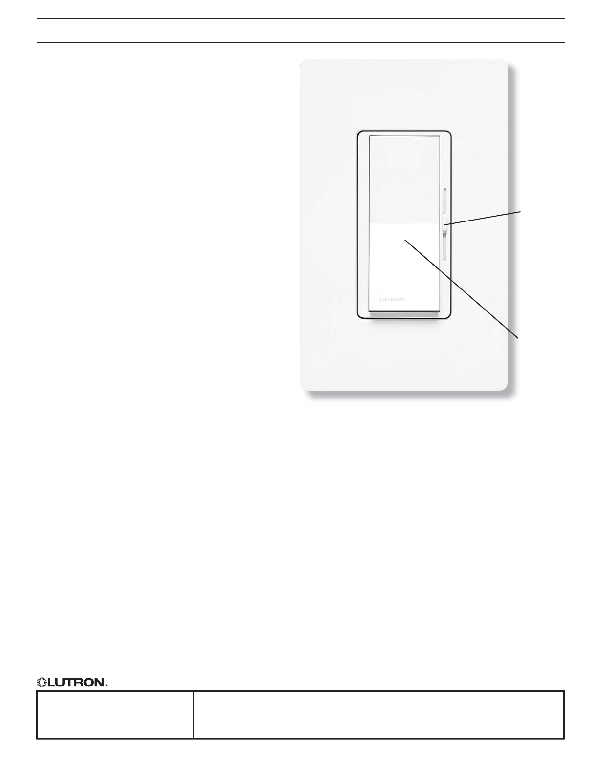
• Large paddle switch with a captive linear-slide
dimmer for a standard designer wallplate opening
Wallbox ControlsC•L® DimmerDiva®
369682a 1 12.03.12
• HED
Technology: Advanced LutronR dimming
™
circuitry designed for compatibility with most high
effi cacy light bulbs
• ULR Listed to control:
— Dimmable compact fl uorescent (CFL) with
integrated ballast
— Dimmable LED with integrated driver
— Halogen
— Incandescent
• Low-end adjustment to accommodate a wide range
of bulbs
• 100% factory tested
Application Requirements
• When dimming CFLs or LEDs, only bulbs marked
or rated as DIMMABLE may be used.
• For a complete list of compatible DIMMABLE CFLs
and LEDs please visit www.lutron.com/dimcfl led.
For questions call 1.800.523.9466.
• Some DIMMABLE CFLs and LEDs require a
minimum number of bulbs for proper operation. For
details and a list of bulbs, please visit
www.lutron.com/dimcfl led.
Select
light level
with slider
Switch on
(to selected
light level),
and off
* Wallplate sold separately
Model Numbers
DVCL-153P-XX
DVSCCL-153P-XX1 Satin Colors,
1
“XX” in the model number represents color/finish code; see
“Colors and Finishes” on next page.
2
For 3-way and 4-way switching, use ClaroR switches or other
mechanical switches.
Job Name:
Job Number:
1
Gloss Finish,
Single pole / 3-way
Single pole / 3-way
SPECIFICATION SUBMITTAL Page
Model Numbers:
2
2
Page 2
Specifi cations
Wallbox ControlsC•L® DimmerDiva®
369682a 2 12.03.12
Regulatory Approvals
• ULR Listed to US and Canadian safety requirements
UL1472 / CSA C22.2 184.1
• NOM
Power and Ratings
• 120 V
60 Hz
• 150 W dimmable CFL/LED
or
• 600 W Incandescent/Halogen
or
• Mixed bulb type per Multigang and Mixed Bulb Type
Ratings table (see page 3)
Environment
• For indoor use only.
• Operating temperatures 32 °F to 104°F (0°Cto 40°C).
Performance
• Power-failure memory
• Captive linear slider
• Electrostatic discharge tested
• Precise color matching
• Mechanical air-gap switch to disconnect load
power
Warranty
• 1 Year Limited Warranty
For additional Warranty information, please visit
http://www.lutron.com/TechnicalDocumentLibrary/
369-119_Wallbox_Warranty.pdf
SPECIFICATION SUBMITTAL Page
Job Name:
Model Numbers:
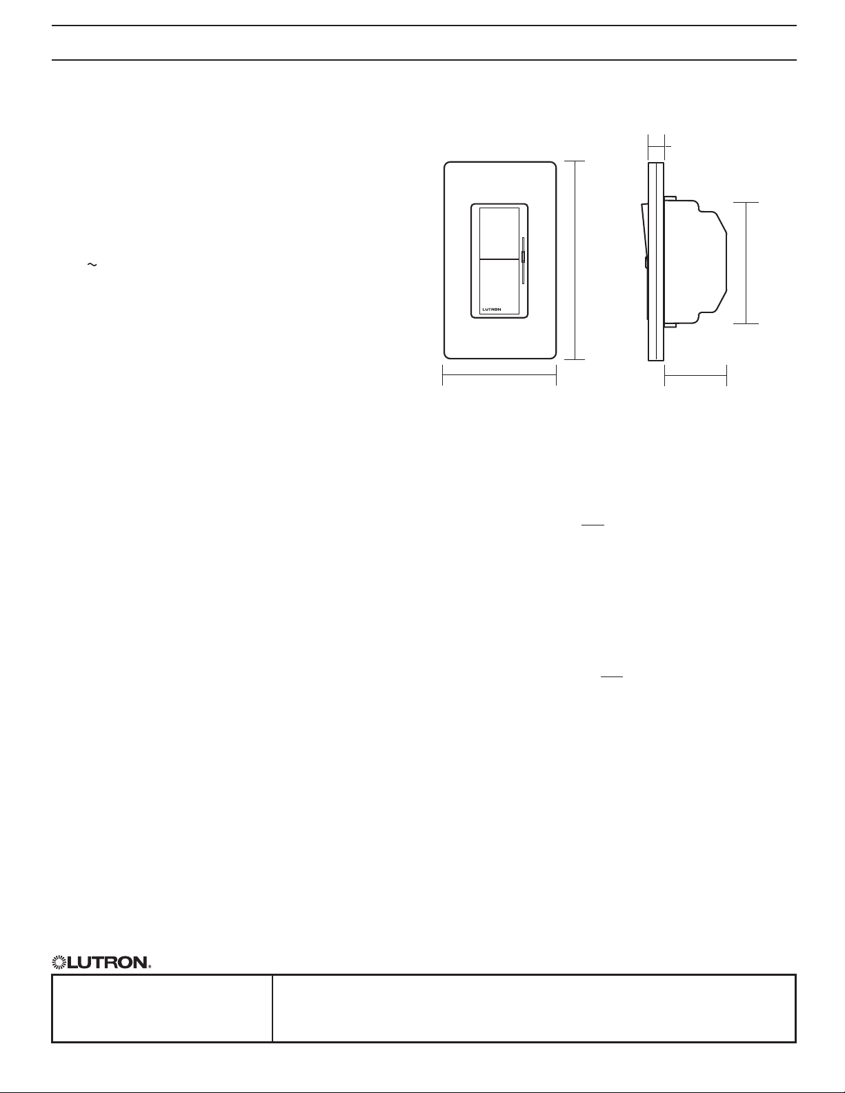
Dimensions
4.69 in
(119 mm)
2.94 in
(75 mm)
Note: Requires a U.S. wallbox 2` in (64 mm)
deep minimum.
Colors and Finishes
Gloss Finishes
Add color/fi nish code to model #
Example: DVCL-153P-WH
WH White
IV Ivory
AL Almond
LA Light Almond
GR Gray
BR Brown
BL Black
Satin ColorsR
Add color/fi nish code to model #
Example: DVSCCL-153P-SW
HT Hot
MR Merlot
PL Plum
TQ Turquoise
SG Sea Glass
TP Taupe
ES Eggshell
BI Biscuit
SW Snow
PD Palladium
MN Midnight
TC Terracotta
SI Sienna
GB Green Briar
BG Bluestone
MS Mocha Stone
GS Goldstone
DS Desert Stone
ST Stone
LS Limestone
0.30 in
(7.6 mm)
1.31 in
(33 mm)
2.75 in
(70 mm)
Job Number:
Page 3

Wallbox ControlsC•L® DimmerDiva®
369682a 3 12.03.12
Multigang and Mixed-Bulb-Type Ratings
When installing more than one Dimmer in the same wallbox, it may be necessary to remove some side sections
prior to wiring (see diagram). Removal of Dimmer side sections may reduce maximum wattage, as shown in
the chart below.
Mixing bulb types (using a combination of CFL/LED, and Incandescent/Halogen bulbs) will also affect the
maximum ratings, as shown in the chart below.
*EXAMPLE: If one set of side sections is removed and you have two 24 W CFL bulbs installed
(Total CFL Wattage = 48 W), you may add up to 300W of incandescent or halogen
lighting.
Do not remove outside
sections
Each Dimmer has inside
sections removed
Total CFL/LED
Wattage Installed
(Wat tage per bu lb x # of bulbs)
0 W + 600 W 500 W 400 W
1 W – 25 W + 500 W 400 W 300 W
26 W – 50 W + 400 W 300 W 200 W
51 W – 75 W + 300 W 200 W 100 W
76 W – 100 W + 200 W 100 W 50 W
101 W – 125 W + 100 W 50 W 0 W
126 W – 150 W + 0 W 0 W 0 W
Middle Dimmer has two side
sections removed
Maximum Allowable Incandescent/Halogen Wattage
No side s removed 1 side re moved 2 sides r emoved
Job Name:
Job Number:
SPECIFICATION SUBMITTAL Page
Model Numbers:
Page 4

Operation (View with wallplate removed)
Wallbox ControlsC•L® DimmerDiva®
369682a 4 12.03.12
Lever-type Adjustment Dial
Switch
1
Turns lights ON and OFF.
1
2
Slider
2
Controls light level.
Up
Increases light level
Down
Decreases light level
IMPORTANT: Set slider to
bottom before adjusting
dimming range.
3
Adjustment lever
3
Sets low end dimming limit.
Up (clockwise)
Increases brightness
Down
(counter-clockwise)
Decreases brightness
OR
Wheel-type Adjustment Dial
Adjustment dial
3
Sets low end dimming limit.
Up (clockwise)
Decreases brightness
Job Name:
Job Number:
Down
(counter-clockwise)
Increases brightness
SPECIFICATION SUBMITTAL Page
Model Numbers:
Page 5

Wiring Diagrams
Single-Pole Wiring
Wallbox ControlsC•L® DimmerDiva®
369682a 5 12.03.12
Line/
Hot
120 V~
60 Hz
Neutral
Black
3-Way Wiring
Dimmer
Line Side
Line/
Black
Hot
120 V~
60 Hz
Neutral
Dimmer
Dimmer
Green
Red
Red/White
Green
Red
Red/White
Lighting
Load
Dimmer
3-Way
Switch
***
*
OR
*** ***
Lighting
Load
Load Side
Line/
Hot
120 V~
60 Hz
Neutral
3-Way
Switch
Red
***
Red/White
*
Dimmer
Green
Black
Lighting
Load
4-Way Wiring
Dimmer
Line Side
Line/
Hot Black
120 V~
60 Hz
Neutral
Dimmer
Load Side
Line/
Hot
120 V~
60 Hz
Neutral
Dimmer
Red
Red/White
Green
3-Way
Switch
***
*
*** ***
†
4-Way
Switch
***
*
***
***
***
OR
4-Way
Switch
**
†
Red
Red/
White
3-Way
Switch
***
*
***
Dimmer
Black
Green
Lighting
Load
Lighting
Load
* or Copper/Black screw terminal
** or Brass/Gold screw terminal
*** or Green screw terminal
†
Please refer to switch instruction
sheet for proper wiring.
Note for 4-Way Wiring:
Dimmer must be installed
Line Side or Load Side. It
cannot be installed in the
4-way location.
Job Name:
Job Number:
SPECIFICATION SUBMITTAL Page
Model Numbers:
 Loading...