

Page 1
ServoOne
User Manual
Page 2
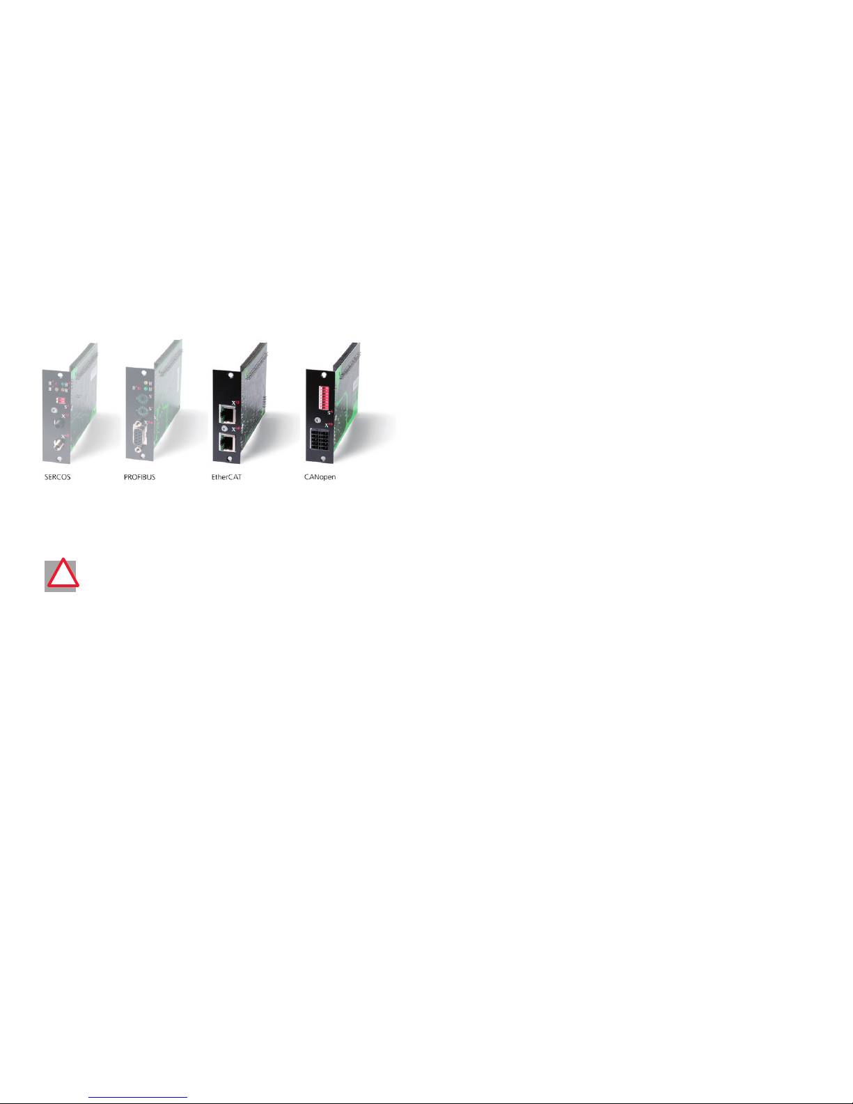
The bus modules for
User Manual ServoOne
CANopen/EtherCAT
ID No.: 1100.28B.0-00
Status: 11/2007
We reserve the right to make technical changes.
This guide is currently subject to approval testing and is therefore
not yet final and complete.
The technical data and agree d properties are therefore provisional
and still subject to change in line with further technical developments.
!
ServoOne
Page 3
User Manual CANopen/EtherCAT
3
How to use the document
Dear User
This manual is intended for project engineers, commissioning engineers or programmers of drive and automation solutions on the CANopen and EtherCAT field bus. It is
assumed that you are already familiar with these field bus systems through appropriate
training and from reading the relevant literature. We assume that your drive is already in
operation
– if not, you should first consult the Operation Manual.
This manual applies for the position controller system ServoOne, so you will
see only the abbreviation SO below.
11
General
44 Commissioning and configuration of CANopen
55 Commissioning and configuration of EtherCAT
66 Setting the device parameters for CANopen
33
Mounting and connection of EtherCAT
22 Mounting and connection of CANopen
77 Setting the device parameters for EtherCAT
88 Implemented DS402 functionality
99 Operation modes DS402
1212 Bibliography
1313 Appendix glossary
1414 Index
1111 EDS file, object directory parameter list
1010 Emergency Objects
Page 4
User Manual CANopen/EtherCAT
4
Pictograms
!
Important! Miso peration may result in damag e to the drive or malfunctions.
Danger from electrical voltage! Improper behaviour may endanger human
life.
Danger from rotating par ts! Drive may star t up automatically.
Note: Useful information
Page 5

User Manual CANopen/EtherCAT
5
Contents
How to use the do cument ......................................................................................................... 3
Pictograms .............................................................................................................................. 4
1
General Intro duction ........................................................................................................... 7
1.1
Measures for your safet y ................................................................................................ 7
1.2
Introduction to CANopen............................................................................................... 7
1.3
Introduction to EtherCAT ............................................................................................... 8
1.4
System requirements ...................................................................................................... 8
1.5 Fur ther
documentation .................................................................................................. 8
2 Mounting and Connection of CANopen ............................................................................
9
2.1 Setting the addres s ........................................................................................................
9
2.2 M eanings of LEDs ..........................................................................................................
10
2.3 Installation ....................................................................................................................
11
2.3 Transmission speeds ......................................................................................................
13
2.4 Display of the operating st ates via 7-segment display ....................................................
13
2.5 Hardware enable ...........................................................................................................
14
3 Mounting and Connection of EtherC AT ...........................................................................
15
3.1 Installation and cab ling .................................................................................................
15
3.2 Pin assignment of the R J-45 socket ...............................................................................
16
3.3 M eanings of LEDs ..........................................................................................................
17
3.4 Display of operating states via 7-segment display ..........................................................
18
3.5 Hardware enable ...........................................................................................................
18
4
Commissio ning and Configuration of CA Nopen ..............................................................19
4.1
Commissioning .............................................................................................................19
4.2
Commissioning sequence ..............................................................................................19
4.2.1
Setting the sof tware address and Baud rate ........................................................20
4.3
Commissioning instruc tions...........................................................................................20
4.4
Testing the higher-order controller ................................................................................20
4.5
Data handling ...............................................................................................................21
4.5.1
Saving the settings ..............................................................................................21
4.5.2
Restoring factor y defaults ...................................................................................21
4.6
Commissioning via DRI VEMANAGER ...................................................................................21
4.7
Control functions ......................................................................................................... 22
4.8
Operation mode s election (Modes of operation) .......................................................... 22
4.8.1
Functionality of operation modes ....................................................................... 23
5 Commissio ning and Configuration of Ether CAT .............................................................
25
6
Setting th e Device Parame ters for C ANopen .................................................................. 27
6.1 Implemented DS301 functi onality .................................................................................
27
6.1.1
Communication objec ts ......................................................................................27
6.1.2 Objec t director y of DS301 ...................................................................................
27
6.2
Parameter channel (Ser vice Data Objec ts) ......................................................................28
6.2.1
Data types...........................................................................................................29
6.2.2
Representation of data types in the control protocol ...........................................29
6.2.3 Access to device parameters ..............................................................................
30
6.3
Examples of SDO handling ........................................................................................... 30
6.3.1
Parameter set download .....................................................................................33
6.4
PDO transmission t ypes ................................................................................................ 34
6.5 Event-controlled
TxPDO transmission............................................................................ 34
Page 6
User Manual CANopen/EtherCAT
6
6.6 P DO mapping ................................................................................................................35
6.6.1
Mapping - general ..............................................................................................35
6.6.2
Mapping notes ....................................................................................................35
6.7
Heartbeat func tion ....................................................................................................... 36
7 Setting th e Device Parame ters for EtherCAT ...................................................................
37
7.1 Supported Ether CAT functionality .................................................................................
37
7.2 Configuration for the operation in a controller .............................................................
40
8 Implemented DS402 Functionality ....................................................................................
41
8.1 Device control and state machine ..................................................................................
41
8.1.1 General information ............................................................................................
41
8.1.2
State machine .....................................................................................................41
8.1.3 Device states .......................................................................................................
42
8.2 O ption codes ................................................................................................................
44
8.3 Device control objec ts ..................................................................................................
45
8.4 Units and scalings, fac tor group ....................................................................................
45
8.5
I/O map, objec t 60FDH..................................................................................................47
8.5.1
Object 60 FDh – Digital input s .............................................................................47
8.5.2
Object 2079h – MPRO _INPUT_STATE ................................................................ 48
8.5.3
Object 208 Fh – MRPO_OU TPUT_S TATE ............................................................. 48
9
Operation modes DS4 02 .................................................................................................... 49
9.1 DS 402 compatible op eration modes ............................................................................
49
9.1.1 Parameter setting of ServoOne for ac tivation via DS 402: ...................................
49
9.1.2 Control word DS402 ..........................................................................................
50
9.1.3 Status word DS402 .............................................................................................
51
9.2
Profile Velocity Mo de ....................................................................................................53
9.2.1 Mode -dependent bits in the control word .........................................................
54
9.2.2 Mode -dependent bits in the status word ...........................................................
54
9.3 Homing mode ...............................................................................................................
55
9.3.1 Mode -specific bits in the control word ...............................................................
56
9.3.2
Mode-sp ecific bits in the s tatus word ................................................................ 56
9.4 Profile position mod e ....................................................................................................
57
9.4.1 Mode -specific bits in the control word ...............................................................
58
9.4.2 Mode -specific bits in the status word ................................................................
58
9.4.3 Functional description ........................................................................................
58
10
Emergenc y Objects .............................................................................................................61
10.1
Error acknowledgement, general ..................................................................................61
10.2
Error acknowledgment via bus system...........................................................................61
11 EDS File, Objec t Directo ry Parameter List ........................................................................
63
11.1 EDS file, object directory ..............................................................................................
63
12 Bibliography .......................................................................................................................
65
13 A ppendix Glossary .............................................................................................................
67
Index .......................................................................................................................................... 69
Page 7
[Chapter 1]
User Manual CANopen/EtherCAT
7
1 General Introduction
1.1 Measures for your safety
The ServoOne family drive devices are quick and safe to handle. For your own safety and
for the safe functioning of your device, please be sure to obser ve the following points:
Read the Operation Manual first
1.
Follow the safet y instructions•
Electric drive s are dangerous:
Electrical voltages > 230 V/460 V:
Dangerously high voltages may still be present 10 minutes after
the power is cut. So alway s make sure the system is no longer live.
Rotating parts
Hot surfaces
•
•
•
Your qualification:
In order to prevent personal injury and damage to property, only
personnel with electrical engineering qualifications may work on the
device.
Knowledge of national accident prevention regulations (e. g. VBG4
in Germany)
Knowledge of layout and interconnection with the CAN bus field bus
•
•
•
U
V
N
L
+
R
B
L
-
L
3
L
2
L
1
U
V
N
L
+
R
B
L
-
L
3
L
2
L
1
During installation o bserve the following instructions:
Always comply with the connection conditions and technical sp ecifications.
Electrical ins tallation standards, e.g. for cable cross-s ection, shiel
ding, etc.
Do not touch electronic components and cont acts (elec trostatic
discharge may destroy components).
•
•
•
1.2 Introduction to CANopen
CANopen is an interconnection concept based on the CAN (Controller Area Network)
serial bus system. CAN has many specific advantages, in particular multi-master capability, real-time capability, resistant response to electromagnetic interference and the high
level of availability and low cost of controller chips. These advantages have resulted in
CAN being introduced into widespread use in automation too.
Simplified cross-manufacturer communication
The integration of any number of devices in a manufacturer-specific network involves
substantial expense. CANopen was developed to solve this problem. In CANopen the
use of CAN identifiers (message addresses), the time response on the bus, the network
management (e. g. system start and user monitoring) and coding of the data contents
is specified in a uniform way. CANopen makes it possible for devices from different
manufacturers to communicate in a network at minimal cost. CANopen uses a subset
of the communication services offered by CAL to define an open interface. The selected
CAL services are summarised in a kind of “user guide“. This guide is called the CANopen
Communication Profile.
CANopen functionality of ServoOne
The CANopen Communication Profile is documented in CiA DS-301 and regulates “how“
communication is executed. It distinguishes between process data objects (PDOs) and
service data objec ts (SDOs). The Communication Profile additionally defines a simplified
network management system.
Based on the communication services of DS-301 (Rev. 4.01), the device profile for vari
able-speed drives DSP-402 (Rev2.0) was compiled. It describes the operation modes and
device parameters supported.
The following sections will provide you with an overview of the CANopen functionality
integrated in ServoOne. There then follows the information necessary for commissioning.
Page 8

User Manual CANopen/EtherCAT
8
1.3 Introduction to EtherCAT
As far as real-time Ethernet systems are concerned, EtherCAT has become well established in the area of automation. The decisive factor here is not only the IEEE802.3/
100BaseTX Ethernet physics known in the home of fice area, but also the excellent value
for money with regard to implementation in the master and slave modules.
Interconnection can be optionally executed in a star, ring or line structure using standard
patch or crossover cables and is therefore easily adapted to the machine infrastructure.
To reduce the amount of training required, familiar communication and device profiles
were used as of the application layer. In this way, users familiar with CANopen profiles
such as CiA DS301 or DSP402 can change over to this new field bus technology with
minimal training.
In ServoOne we have combined all our past experiences in the CANopen area with this
new field bus technology and achieved maximum compatibility and functionality.
1.4 System requirements
It is assumed you have a standard CANopen setup program and a CANopen interface
driver.
For the precise protocol definitions refer to the CAL specification.
With the aid of these objects it is possible to configure the actual CANopen communication very flexibly and adapt it to the specific needs of the user.
1.5 Further documentation
Operation Manual, for commissioning of the drive unit
Application Manual, for additional parameter setting to adapt to the application.
The Application Manual can be downloaded as a PDF file from our website at
http://ww w.lust-tec.de. Follow the Service link.
CiA DS-301 (Rev. 4.0): Application Layer and Communication Profile
CiA DSP-402 (Rev. 2.0): Device Profile Drives and Motion Control
EtherCAT Communication Specification Version 1.0 2004
EtherCAT Indicator Specification Proposal V0.91 2005
IEC61158-2-12 to IEC61158-6-12
•
•
•
•
•
•
•
Page 9
User Manual CANopen/EtherCAT
9
[Chapter 2]
2 Mounting and Connection
of CANopen
Attention: Do NOT insert or remove the CANopenconnector during opera-
tion.
2.1 Setting the address
Step Action Note
1.
Find out which address is assigned to
the module you are inst alling.
Ask your projec t engineer.
2.
Select the mo de of addressing:
by bus address parameter
by DIP switch (S4)
by bus address parameter and DIP switch (S4)
•
•
•
See below
Address setting finished; for further procedure see Installation.
!!
Three possible methods of address assignment
Only using bus address parameter 2005- COM_CAN_Adr: You will find parameter
2005-COM_CAN_ Adr (factory setting 1) in the “field bus“ subject area under
CANopen.
Only using DIP switch S4
Combination of bus address parameter and DIP switch S4
CAN address = hardware address (S4) + Parameter 2005-COM_CAN_Adr
This option is advantageous, for example, if you intend always to use the same
parameter set with up to 15 drives, but the lowest address is 30. Parameter
2005-COM_CAN_ Adr is then set to 30. The device address is then defined using
the coding switch, which ranges from 0-15.
T
y
p
e
:
In
:
O
u
t
:
3
5
6
3
3
L
a
h
n
a
u
w
w
w
.
l
u
s
t
-
t
e
c
.
d
e
M
a
d
e
in
G
e
r
m
a
n
y
U
S
C
L
IS
T
E
D
I
n
d
.
C
o
n
t.
E
q
.
1
9
B
B
SN.
:
S
O
A
8
4
.
0
0
6
.
0
0
0
0
.
0
0
0
0
.
0
24
23
22
21
20
19
18
17
16
15
14
13
12
11
10
9
8
7
6
5
4
3
2
1
REL
REL
ISDS
H
IS
D
06
IS
D
05
IS
D
04
ISD03
IS
D
02
IS
D
01
ISD00
+
24
V
D
GN
D
RS
H
RS
H
EN
P
O
OSD0
2
OSD0
1
OSD0
0
ISA1
-
ISA1
+
ISA0
-
ISA0
+
+2
4
V
DGND
A
C
H
T
U
N
G
W
A
R
N
I
N
G
K
o
n
d
e
n
s
a
t
o
r
e
n
e
n
t
-
l
a
d
e
z
e
i
t
>
3
m
i
n
.
B
e
t
r
i
e
b
s
a
n
l
e
i
t
u
n
g
b
e
a
c
h
t
e
n
!
C
a
p
a
c
i
t
o
r
d
i
s
c
h
a
r
g
e
t
i
m
e
>
3
m
i
n
.
P
a
y
a
t
t
e
n
t
i
o
n
t
o
th
e
o
p
e
r
a
t
i
o
n
m
a
n
u
a
l
!
o
n
e
S
e
r
v
o
5
6
x
3
x
1
x
2
x
4
x
5
x
1
0
x
9
x
6
x
7
x
8
x
1
1
L
1
L
2
L
3
ϑ
-
ϑ
+
ϑ-
ϑ+
ϑ
-
ϑ
+
ϑ-
ϑ+
12 3 45 67 8
x
3
2
s
4
x
3
3
h
14
h
15
AC
H
TUNG
WA
R
NING
K
on
d
ens
a
tore
nen
t-
lad
e
z
eit
>
3
m
in.
B
etriebsa
nle
itu
n
g
bea
c
hten
!
C
ap
a
cit
o
r disc
harg
e
ti
m
e
>
3
Pa
y
a
tt
en
ope
1 2 3 4 5 6 7 8
s
4
x
33
h
14
h
15
Figure Position of C AN connection on ServoOne
1.
2.
3.
Page 10

User Manual CANopen/EtherCAT
10
Address set ting using DIP switch
An address between 0 and 127 can be decimally selected using DIP switch S4 on the
position controller.
The DIP switch is assigned as follows: Positions 1-7 are reserved for the address setting,
position 8 for the activation/deactivation of the 120 Ohm bus termination in the device.
Function/assignment:
Dip switch 1 - ð significance 20 = 1
Dip switch 2 - ð significance 21 = 2
Dip switch 3 -
ð significance 22 = 4
...
Dip switch 7 - ð significance 26 = 64
Dip switch 8 = Bus termination ON/OFF
1 2 3 4 5 6 7 8
Figure DIP switch
Example of use of the DIP switches:
Setting address “3“ using the Dip switch:
- ð Set switch 1 and switch 2 to ON
- ð 20 + 21 = 3
- ð Resultant device address = 3
- ð (If the software address = 0 is set)
IMPORTANT: Switch 8 = Bus termination!!!
Note: Changes to the CAN address are applied on a
- Reset node command
- Restart (device power-up).
Note: The active bus address can be found in the boot-up message.
2.2 Meanings of LEDs
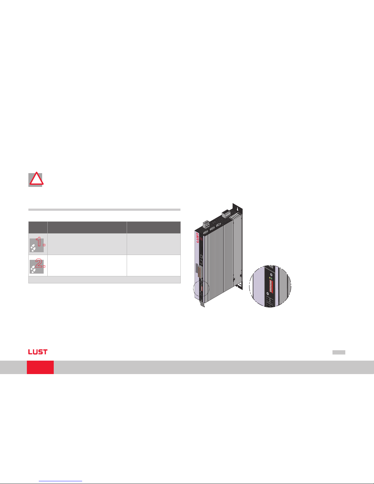
The CAN option of ServoOne has two diagnosis LEDs (H14, H15).
AC
H
TUNG
WA
R
NIN
G
K
on
den
sa
tore
nent-
lad
ezeit
>
3
m
in.
B
etriebsanleitu
n
g
bea
c
hten!
C
ap
a
cit
or disc
harge
tim
e
>
3
m
in.
P
ay
at
t
ention to
th
e
ope
ra
tion
m
anual!
1 2 3 4 5 6 7 8
x
32
s
4
x
33
h
14
h
15
Figure Device with C ANopen option
!!
Page 11
User Manual CANopen/EtherCAT
11
[Chapter 2]
The LEDs have the following function:
LED Function Meaning
H14 (yellow LED)
CANopen
network state
The LED displays the current network st ate.
NMT STOPPED
ð flashing with 800 ms cycle
NMT PRE- OPERATIONAL
ð flashing with 1600 ms cycle
NMT OPER ATIONAL
ð permanently lit.
•
•
•
H15 (green LED)
Voltage supply CAN
option
Permanently lit, if the 24V supply of the option
from CAN bus applies.
Table Meanings of LEDs
2.3 Installation
Step Action Note
1.
Make sure the hardware enable is wire d on
ServoOne ( X4).
see Operation Manual
2.
Wire the CAN connection using connec tor X32
Connection of CAN signal cables
Connection of interface power supply
Activation of the internal bus terminating
resistor on the final drive controller
•
•
•
see Specification of CAN bus
connection table and Assign ment of connection X19 table
3.
Switch on the drive device.
Electrical ins tallation is finished; for how to pro ceed further, refer to sec tion 4
“Commissioning and configuration“.
The CANopen interface is integrated in ServoOne. The connection is made via connector X32. The interface is isolated from the drive controller electronics. The supply to the
isolated secondary side is provided by the customer via connector X32.
Page 12
User Manual CANopen/EtherCAT
12
T
y
p
e
:
I
n
:
O
u
t
:
3
5
6
3
3
L
a
h
n
a
u
w
w
w
.
l
u
s
t
-
t
e
c
.
d
e
M
a
d
e
i
n
G
e
r
m
a
n
y
U
S
C
L
I
S
T
E
D
I
n
d
.
C
o
n
t
.
E
q
.
1
9
B
B
S
N
.
:
S
O
A
8
4
.
0
0
6
.
0
0
0
0
.
0
0
0
0
.
0
24
23
22
21
20
19
18
17
16
15
14
13
12
11
10
9
8
7
6
5
4
3
2
1
RE
L
RE
L
ISDS
H
ISD0
6
ISD0
5
ISD0
4
ISD0
3
ISD0
2
ISD0
1
ISD0
0
+2
4
V
DG
N
D
RS
H
RS
H
EN
P
O
OSD
0
2
OSD
0
1
OSD
0
0
ISA1
-
ISA1
+
ISA0
-
ISA0
+
+2
4
V
DG
N
D
A
C
H
T
U
N
G
W
A
R
N
I
N
G
K
o
n
d
e
n
s
a
t
o
r
en
e
n
t
-
la
d
e
z
e
it
>
3
m
in
.
B
e
t
r
ie
b
s
a
n
l
e
it
u
n
g
b
e
a
c
h
t
e
n
!
C
a
p
a
c
i
t
o
r
d
is
c
h
a
r
g
e
t
i
m
e
>
3
m
in
.
P
a
y
a
t
t
e
n
t
i
o
n
t
o
th
e
o
p
e
r
a
t
io
n
m
a
n
u
a
l!
o
n
e
Se
r
vo
5
6
x
3
x
1
x
2
x
4
x
5
x
1
0
x
9
x
6
x
7
x
8
x
1
1
L
1
L
2
L
3
ϑ
-
ϑ
+
ϑ-
ϑ+
ϑ
-
ϑ
+
ϑ-
ϑ+
1234 567 8
x
1
9
s
4
L-
L1
L+
N
24 VDC
CA N - B u s
1112 1314
1516 1718 1920
12 3 45 6 78 9 10
1112 131415 16 1718 1920
12 3 4
56 7 89 10
SPS/PLC
T
y
p
e
:
I
n
:
O
u
t
:
3
5
6
3
3
L
a
h
n
a
u
w
w
w
.
l
u
s
t
-
t
e
c
.
d
e
M
a
d
e
i
n
G
e
r
m
a
n
y
U
S
C
L
I
S
T
E
D
I
n
d
.
C
o
n
t
.
E
q
.
1
9
B
B
S
N
.
:
S
O
A
8
4
.
0
0
6
.
0
0
0
0
.
0
0
0
0
.
0
24
23
22
21
20
19
18
17
16
15
14
13
12
11
10
9
8
7
6
5
4
3
2
1
RE
L
RE
L
ISDSH
ISD
0
6
ISD
0
5
ISD
0
4
ISD
0
3
ISD
0
2
ISD
0
1
ISD
0
0
+2
4
V
DG
N
D
RSH
RSH
EN
P
O
OSD0
2
OSD0
1
OSD0
0
ISA1-
ISA1
+
ISA0-
ISA0
+
+2
4
V
DG
N
D
A
C
H
T
U
N
G
W
A
R
N
I
N
G
K
o
n
d
e
n
s
at
o
r
e
n
e
n
t
-
l
a
d
e
z
e
it
>
3
m
i
n
.
B
e
t
r
ie
b
s
a
n
l
e
i
t
u
n
g
b
e
a
c
h
t
e
n
!
C
a
p
a
c
it
o
r
d
is
c
h
a
r
g
e
t
im
e
>
3
m
in
.
P
a
y
a
t
t
e
n
t
i
o
n
t
o
t
h
e
o
p
e
r
a
t
io
n
m
a
n
u
a
l!
o
n
e
Se
r
vo
5
6
x
3
x
1
x
2
x
4
x
5
x
1
0
x
9
x
6
x
7
x
8
x
1
1
L
1
L
2
L
3
ϑ
-
ϑ
+
ϑ-
ϑ+
ϑ
-
ϑ
+
ϑ-
ϑ+
1234 567 8
x
1
9
s
4
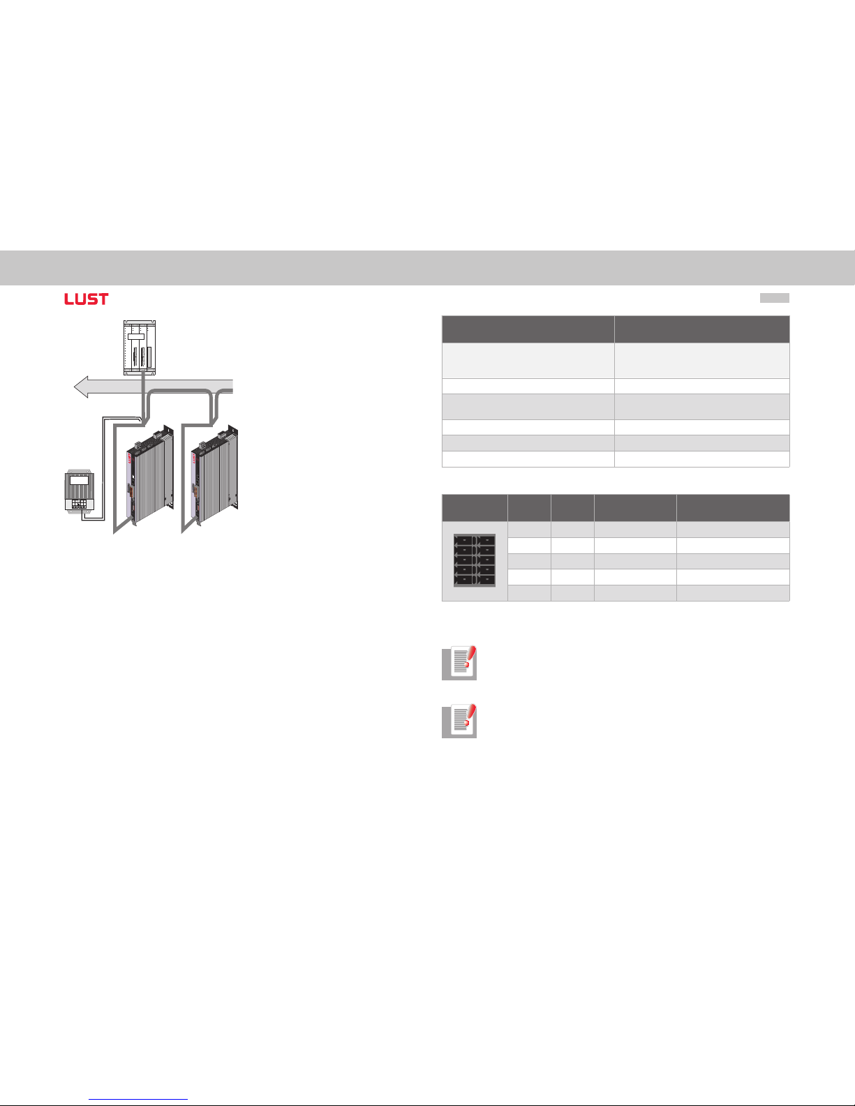
Figure System connection
Connection Spring-type terminal
Wave terminating resistance
- Bus termination -
120 W (internal)
Activation of the bus termination in the device
via switch 8 in the CAN option
Max. Input frequency 1 MHz
Ext. voltage supply
+24 V +25 %, 50 mA
(isolated from drive controller)
Voltage ripple Max. 3 Vss
Current consumption Max. 50 mA per user
Cable type 4-wire, surge impedance 120 W
Table Specification of CAN bus connection
Terminal X32 PIN PIN Function Description
10 5 CAN _+24V external 24V supply
9 4 CAN _H CAN High
8 3 CAN _SHLD CAN Shield (optional)
7 2 CAN _L CAN Low
6 1 CAN _GND CAN Ground (0V)
Table Assignment of connection X19
Note: Both connectors of terminal X32 are connected to each other in the
device.
Note: The external 24 V supply for the option board is essential. It is not sup-
plied by the device.
Page 13
User Manual CANopen/EtherCAT
13
[Chapter 2]
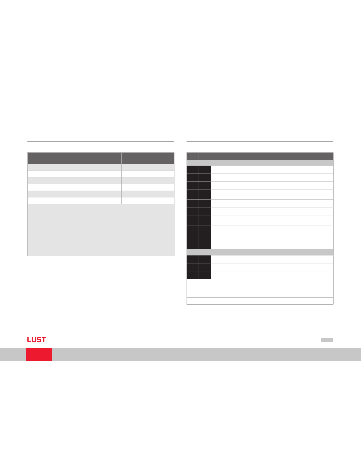
2.3 Transmission speeds
The CAN bus can be operated at the following Baud rates:
Transmission
speed
Maximum line length across
the complete net work 1)
1000 kBaud 25 m Factory setting
500 KBaud 100 m
250 kBaud 2) 250 m
125 kBaud 2) 500 m
50 kBaud 3)
1000 m
25 kBaud 3)
2500 m
1) Rounded bus length e stimation (wor st case) on basis 5 ns/m
propagation d elay and a total effe ctive device internal in- out
delay as follows:
1M-800 kb it/s: 210 ns
500 - 250 kbit /s: 300 ns (includes 2 * 40 ns for o ptocouplers)
125 kbit/s: 450 ns (incl udes 2 * 100 ns for optoco uplers)
50 -10 kbit/s: Effec tive delay = delay recessive to do minant plus
dominant to reces sive divided by t wo.
2) For bus length greate r than about 200 m th e use of optocoupl ers is recommen ded. If optocou plers are
placed betw een CAN Controll er and transceive r this affect s the maximum bus length depen ding upon
the propagati on delay of the optoc ouplers i.e. - 4m per 10 ns propagati on delay of employe d optocoup
-
ler type.
3) For bus length greate r than about 1 km bri dge or repeater d evices may be nee ded.
Table Transmission speeds
When selecting the transmission rate it should, however, be ensured that the line length
does not exceed the permissible line length for the transmission rate in question.
2.4 Display of the operating states via 7-segment display
D1 D2 Meaning Parameter
System states
8. 8.
Device in reset state
0.
Auto-initialis ation on device startup (Start)
S.*)1.
1) Not ready to switch on (no DC-link voltage) (NotReadyToSwitchOn)
S.*)2.
1) Switch-on inhibit (DC-link is OK, power stage
not ready)
(SwitchOnDisabled)
3.
Ready to switch on (p ower stage is ready) (ReadyToSwitchOn)
4.
On (power is connec ted to the device)2) (SwitchedOn)
5.
Drive ready (current applied to drive and drive
ready for reference input) 2)
(OperationEnable)
6.
Quick stop 2) (QuickStopActive)
7.
Fault response active 2) (FaultReactionActive)
E R
Fault (see below) (Fault)
Displayed in the event of a fault
E R.
Display for errors or non-acknowledgeable errors
X X
Error number (decimal)
Y Y
Error localization (decimal)
1) S. flashes, if the func tion STO (Safe Torque Off) is ac tive, the display is n ot lit if the funct ion is not
active.
*) It does not involve a “sa fe display“ under the t erms of EN 61800-5 -2.
2) The point flashes if th e power stage is a ctive.
Page 14
User Manual CANopen/EtherCAT
14
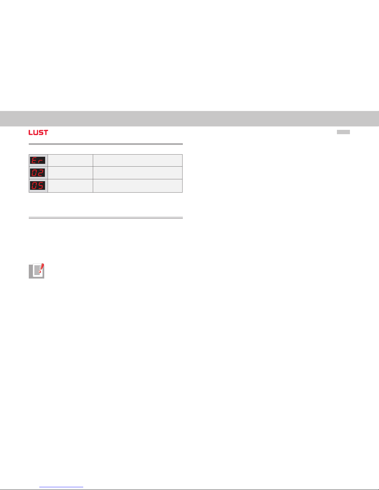
Example of the flash sequence:
ER > 02 > 05 * ER > 02 > 05 ...
Error: ER = “Fault“
Error name: 02 = “Error in the parameter list“
Description of error: 05 = “Function for checking current parameter list“
2.5 Hardware enable
ServoOne has a control input for ENPO hardware enable on the control terminal.
This input must be configured to operate the power stage at 24 V.
The device also provides the function “STO (Safe Torque Off)“ (see Operation Manual or
Application Manual ServoOne), category 3, control terminal ISDSH. For these devices the
relevant function logic must be implemented by way of the higher-order controller as
per the Application Manual.
Note: Without configuration of the inputs ENPO and ISDSH the device stays
in state 1 = “Not Ready to Switch On“ or 2 = “Switch On Disabled“.
Only after correct configuration can the state be exited by a “Shutdown“
command via bus.
�
Page 15
User Manual CANopen/EtherCAT
15
[Chapter 3]
3 Mounting and Connection
of EtherCAT
3.1 Installation and cabling
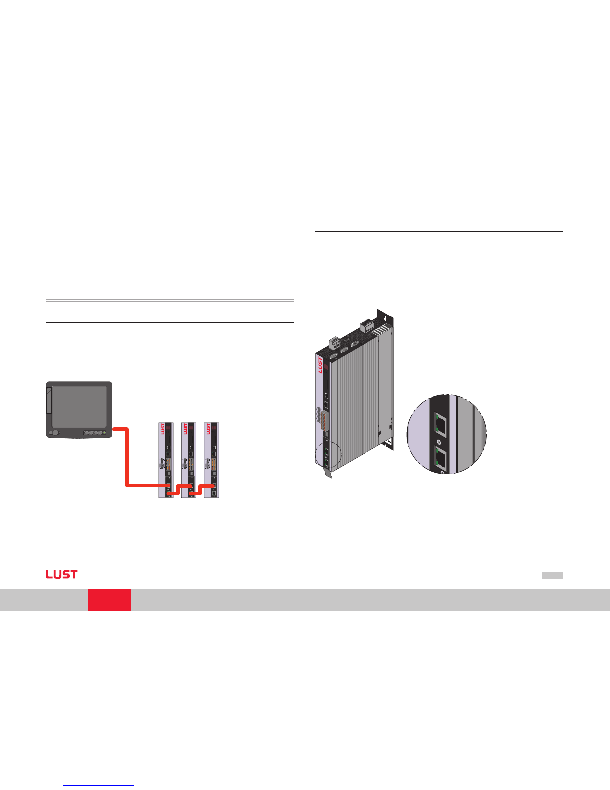
Setup of the EtherCAT network
In an EtherCAT network there is always one EtherCAT master (e. g. an industrial PC)
and a variable number of slaves (e. g. servo controller, bus terminals etc.). Each Ether
CAT slave has two Ethernet ports. Slave to slave cabling is thus possible. All EtherCAT
users are generally put together in a line with the master at the beginning of the circuit.
On the last slave in the line the second Ethernet port remains open.
24
23
22
21
20
19
18
17
16
15
14
13
12
11
10
9
8
7
6
5
4
3
2
1
REL
REL
ISDSH
ISD06
ISD05
ISD04
ISD03
ISD02
ISD01
ISD00
+24 V
DGND
RSH
RSH
ENPO
OSD02
OSD01
OSD00
ISA1-
ISA1+
ISA0-
ISA0+
+24 V
DGND
ACHTUNG
WARNING
Kondensatorenent-
ladezeit > 3 min.
Betriebsanleitung
beachten!
Capacitor discharge
time > 3 min.
Pay attention to the
operation manual!
one
Servo
56
x
3
x
1
x
2
x
4
x
5
12 34 56 78
x
19
s
4
x
15
x
16
24
23
22
21
20
19
18
17
16
15
14
13
12
11
10
9
8
7
6
5
4
3
2
1
REL
REL
ISDSH
ISD06
ISD05
ISD04
ISD03
ISD02
ISD01
ISD00
+24 V
DGND
RSH
RSH
ENPO
OSD02
OSD01
OSD00
ISA1-
ISA1+
ISA0-
ISA0+
+24 V
DGND
ACHTUNG
WARNING
Kondensatorenent-
ladezeit > 3 min.
Betriebsanleitung
beachten!
Capacitor discharge
time > 3 min.
Pay attention to the
operation manual!
one
Servo
56
x
3
x
1
x
2
x
4
x
5
12 34 56 78
x
19
s
4
x
15
x
16
24
23
22
21
20
19
18
17
16
15
14
13
12
11
10
9
8
7
6
5
4
3
2
1
REL
REL
ISDSH
ISD06
ISD05
ISD04
ISD03
ISD02
ISD01
ISD00
+24 V
DGND
RSH
RSH
ENPO
OSD02
OSD01
OSD00
ISA1-
ISA1+
ISA0-
ISA0+
+24 V
DGND
ACHTUNG
WARNING
Kondensatorenent-
ladezeit > 3 min.
Betriebsanleitung
beachten!
Capacitor discharge
time > 3 min.
Pay attention to the
operation manual!
one
Servo
56
x
3
x
1
x
2
x
4
x
5
12 34 56 78
x
19
s
4
x
15
x
16
IPC
Figure EtherCAT connection
IN and OUT socket (R J-45 input/output)
Each EtherCAT slave has two RJ- 45 sockets. The upper por t (X15) is the (IN) input and
the lower port (X16) is the (OUT) output of the slave. The incoming cable (from the
direction of the master) is connected using the IN port, the outgoing cable is connected
to the next slave using the OUT port. The OUT port remains blank for the last slave in
the series. In the case of a slave an open output leads internally to a logical short circuit
of the transmit (Tx) and receive (Rx) cables. For this reason every EtherCAT network can
be regarded as a logical ring in terms of its topology.
Figure EtherCAT option
T
y
p
e
:
In
:
O
u
t
:
3
5
6
3
3
L
a
h
n
a
u
w
w
w
.
lu
s
t
-
t
e
c
.
d
e
M
a
d
e
in
G
e
r
m
a
n
y
U
S
C
L
IS
T
E
D
In
d
.
Co
n
t
.
E
q
.
1
9
B
B
SN.
:
S
O
A
8
4
.0
0
6
.0
0
0
0
.0
0
0
0
.0
24
23
22
21
20
19
18
17
16
15
14
13
12
11
10
9
8
7
6
5
4
3
2
1
REL
REL
ISDSH
ISD0
6
ISD0
5
ISD0
4
ISD0
3
ISD0
2
ISD0
1
ISD0
0
+
24
V
D
GN
D
RS
H
RS
H
EN
P
O
OSD02
OSD01
OS
D00
ISA1
-
ISA1
+
ISA0
-
ISA0
+
+2
4
V
DGND
A
C
H
T
U
N
G
W
A
R
N
IN
G
K
o
n
d
e
n
s
a
t
o
r
e
n
e
n
t
-
l
a
d
e
z
e
i
t
>
3
m
i
n
.
B
e
t
r
i
e
b
s
a
n
l
e
i
t
u
n
g
b
e
a
c
h
t
e
n
!
C
a
p
a
c
i
t
o
r
d
i
s
c
h
a
r
g
e
t
i
m
e
>
3
m
i
n
.
P
a
y
a
t
t
e
n
t
i
o
n
t
o
t
h
e
o
p
e
r
a
t
i
o
n
m
a
n
u
a
l
!
o
n
e
S
e
r
v
o
5
6
x
3
x
1
x
2
x
4
x
5
x
1
0
x
9
x
6
x
7
x
8
x
1
1
L
1
L
2
L
3
ϑ
-
ϑ
+
ϑ-
ϑ+
ϑ
-
ϑ
+
ϑ-
ϑ+
x
1
5
x
1
6
AC
H
TUN
G
WA
R
NING
Ko
n
dens
at
o
rene
n
t-
ladeze
it > 3
min.
Be
t
riebsanleit
un
g
beac
ht
e
n!
Capa
citor discha
rg
e
time > 3
m
in
.
Pa
y
atte
ntion
to th
e
oper
at
i
on
manual
!
x
15
x
16
upper RJ- 45 port = input
lower RJ- 45 port = output
Page 16
User Manual CANopen/EtherCAT
16
IMPORTANT: Errors in cabling (incorrect connection of input and output)
can lead to faulty addressing by the master.
Connecting cable
Ethernet patch cables or crossover cables are suitable connection cables as per
the CAT5e specification. Cables lengths of 0.3 to a max. 100 m are permissible.
!!
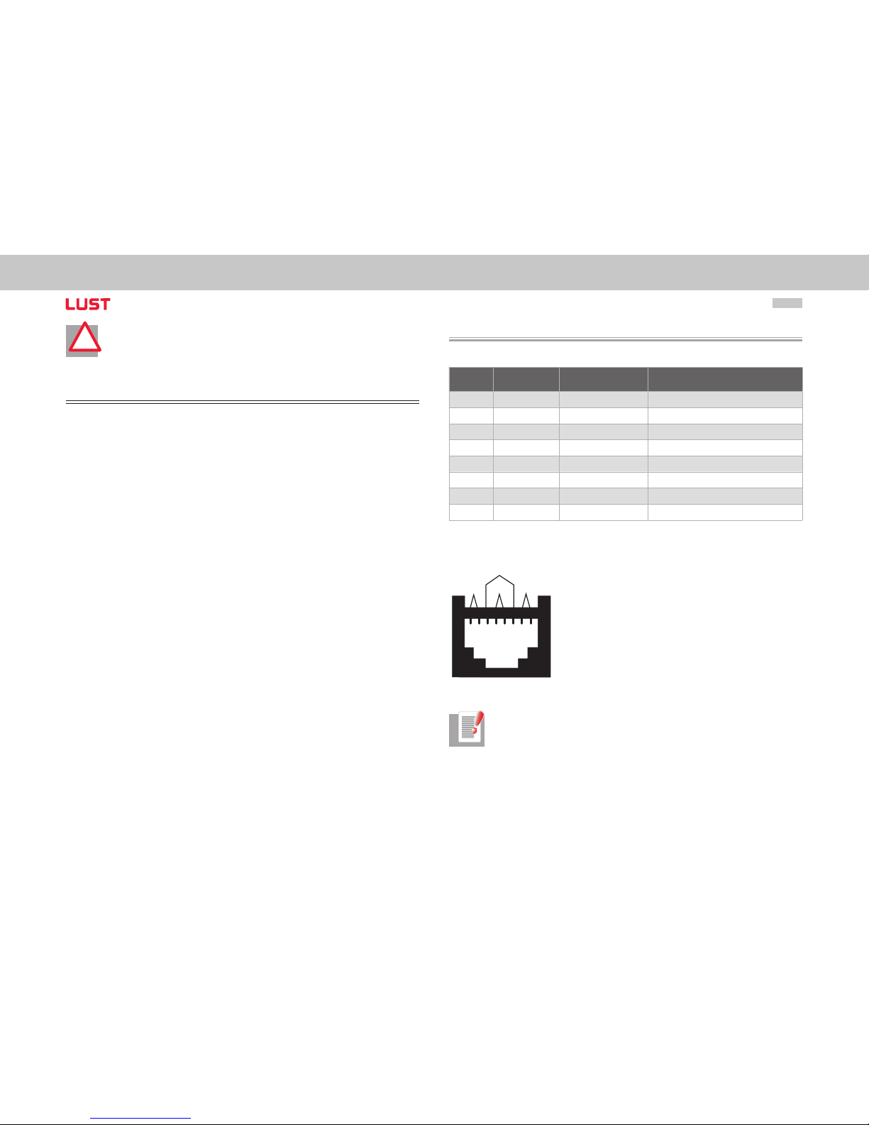
3.2 Pin assignment of the RJ-45 socket
The RJ- 45 socket is assigned as follows:
PIN Colour Cable wire pairs Function
1 white/orange 2 TxData +
2 orange 2 TxData -
3 white/green 3 RecvData +
4 blue 1 Unused
5 white/ blue 1 Unused
6 green 3 RecvData -
7 white/brown 4 Unused
8 brown 4 Unused
Table Pin assignment
1 2 3 4 5 6
7 8
2
4
1
3
Pair #
Figure RJ-45 socket
NOTE: Ethernet cables are available in the IT specialist trade in various
lengths. Use CAT5e cable or better.
Page 17
User Manual CANopen/EtherCAT
17
[Chapter 3]
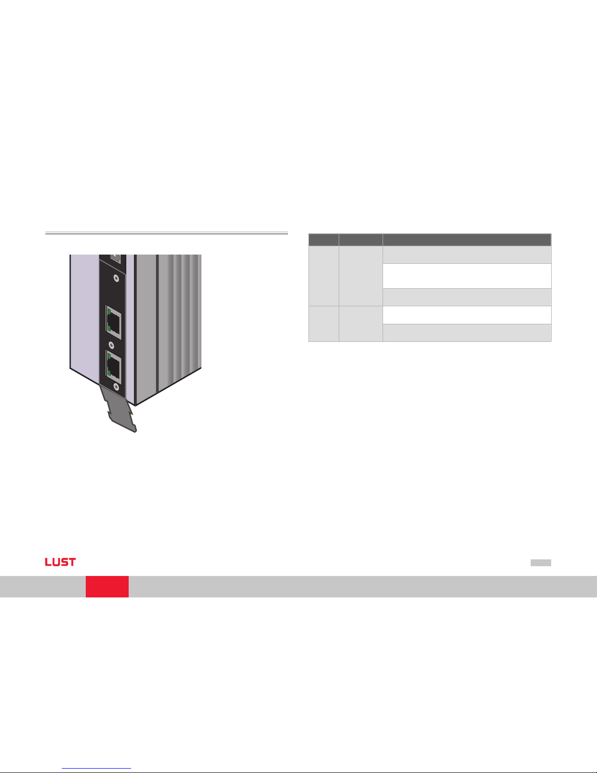
3.3 Meanings of LEDs
There are 2 LEDs on each RJ -45 socket.
ACHTUN
G
W
ARNING
Ko
n
dens
a
tor
e
nent
-
ladeze
i
t > 3 mi
n
.
Betr
iebsan
leitung
bea
c
hten!
Capa
citor
disch
arge
time >
3
min
.
Pa
y at
t
ent
i
on
t
o th
e
oper
a
ti
o
n ma
nual
!
x
15
x
16
Figure Device with EtherCAT option
They have the following meanings:
LED Function Meaning
Upper
LED
Link LED
off = no Link
ð No connection w ith another user
on = Link
ð Connection with another user exist s. Currently no data exchange.
toggle = activity
ð Flashing of the LED signals that data is being exchanged.
Lower LED Speed LED
off = 10 mbit/s
ð There is a connection with a transmission rate of 10 mbit /s.
on = 100 mbit
ð There is a connection with a transmission rate of 100 mbit/s.
Table LED meanings
Page 18
User Manual CANopen/EtherCAT
18
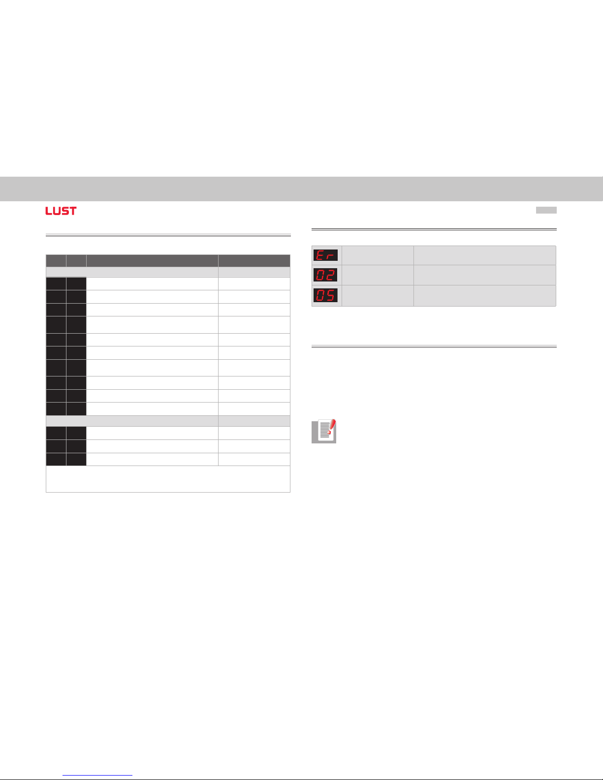
3.4 Display of operating states via 7-segment display
D1 D2 Meaning Parameter
System states
8. 8.
Device in reset state
0.
Auto-initialization on device startup (Start)
S.*)1.
1) Not ready to switch on (no DC-link voltage) (NotReadyToSwitchOn)
S.*)2.
1) Switch-on inhibit (DC-link is OK,
power stage not ready)
(SwitchOnDisabled)
3.
Ready to switch on (p ower stage is ready) (ReadyToSwitchOn)
4.
On (power is connec ted to the device)2) (SwitchedOn)
5.
Drive ready (current applied to drive and ready
for reference input) 2)
(OperationEnable)
6.
Emergency stop 2) (QuickStopActive)
7.
Fault response active 2) (FaultReactionActive)
E R
Fault (see below) (Fault)
Appears in the event of error
E R.
Display for errors or non-acknowledgeable errors
X X
Error number (decimal)
Y Y
Error localization (decimal)
1) S. flashes, if the func tion STO (Safe Torque O ff) is ac tive, the display is no t lit if the functi on is not activ e.
*) It does not involve a “safe d isplay“ under the t erms of EN 61800-5 -2.
2) The point flashes i f the power sta ge is active.
Example of the flash sequence:
ER > 02 > 05 * ER > 02 > 05 ...
Error: ER = “Fault“
Error name: 02 = “Error in the parameter list“
Description of error: 05 = “Function for checking current parameter list“
3.5 Hardware enable
ServoOne has a control input for ENPO hardware enable on the control terminal.
This input must be configured to operate the power stage at 24 V.
The device also provides the function “STO (Safe Torque Off)“ (see Operation Manual or
Application Manual ServoOne), category 3, control terminal ISDSH. For these devices the
relevant function logic must be implemented by way of the higher-order controller as
per the Application Manual.
Note: Without configuration of the inputs ENPO and ISDSH the device stays
in state 1 = “Not Ready to Switch On“ or 2 = “Switch On Disabled“.
Only after correct configuration can the state be exited by a “Shutdown“
command via bus.
➢
Page 19
User Manual CANopen/EtherCAT
19
[Chapter 4]
4 Commissioning and Configura-
tion of CANopen
4.1 Commissioning
The DriveManager user interface is used for general commissioning of the drive system.
The DriveManager includes tools to identif y motor data, provide access to a motor database for servo motors, and for general device configuration.
Initial commissioning is a separate subject with regard to operation via the user interface,
and is detailed in the device‘s Application Manual.
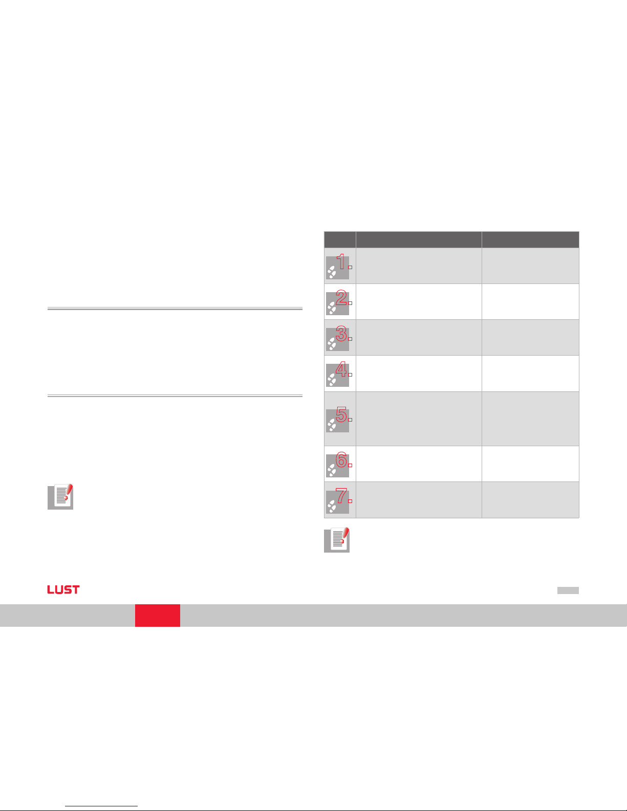
4.2 Commissioning sequence
Preconditions:
The drive device is wired as specified in the Operation Manual and first commissioning is complete. (To test CAN communication, it is sufficient to connect the
voltage supply of the CAN option and the control voltage).
If current is to be applied to the motor, the hardware enable (ENPO) and the
“STO (Safe Torque Off)“ must also be correctly configured.
Note: For more detailed information on optimisation of the software func-
tions and control circuits refer to the device application manual.
•
•
Step Action Note
1.
Check the wiring. Please note that hardware
enable ENPO (X4) is not configured.
2.
Switch on the mains power and the
24 V supply to the CAN interface.
3.
Configure the drive unit using
the Application M anual.
(Inputs/outputs, soft ware
functions, etc.)
4.
Test the control quality and optimise
the controller settings as necessar y
using the Operation Manual.
5.
Set the parameters for the CAN communication. The Baud rate and the device address
are required. The address can be selec ted by
software and hard ware.
The mapping must also be completed and
the active operation mode selected as per
DS301/402.
Software and hard ware address
are added...
6.
Test the drive on the higher-ord er controller
- see sectio n 3.4.
7.
Finally, save the setting.
Save device setting ð
Non volatile in device
Note: For more information on the subject of “Units and scalings“ refer to
section 5.4.
Page 20
User Manual CANopen/EtherCAT
20
4.2.1 Setting the software address and Baud rate
The software address and Baud rate can be set using the following device parameters via
DriveManager:
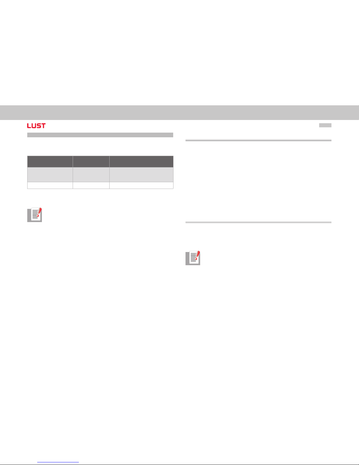
Parameter Func tion Description
2005-COM _CAN_ Adr CANopen address
Address assignment via parameter
For more information on s etting the
address, see se ction 2.1
2006- COM_CAN _Baudrate Baud rate Permissible Baud rates - see section 2.3
Table Parameters on the Bus Syste ms function screen
Note: ServoOne has a default Baud rate of 1 mbit.
4.3 Commissioning instructions
For a variety of reasons, it may be that a drive device does not respond to a telegram:
There is no reply if the telegram frame (Baud rate, data length) on the master
computer is not correct.
There is no reply if a drive device is addressed with the wrong bus address.
There is no reply if the serial connection between the master computer and the
drive device is not correctly set up.
There is no reply if the 24 V supply to the CAN connection is missing or the
cabling is faulty.
There is no valid reply if several devices with the same device address are connected to the bus.
There is no reply if the device has certain network states.
4.4 Testing the higher-order controller
To activate changed settings the device must be switched off and back on again. When
the power is connected, after an initialisation period of a few seconds the device must
transmit a one-off boot-up message (ID 700h + node ID = 701h for device address 1).
If this happens, the communication is OK.
Note: During transfer of data to the device via SDO telegrams the number
of data bytes transferred should be taken into account. For this the correct
length information must be transferred in the control byte.
Alternatively, however, an SDO transfer without specification of the data
length is also possible. The correct operation of the control byte in the
SDO telegram should also be observed.
•
•
•
•
•
•
Page 21
User Manual CANopen/EtherCAT
21
[Chapter 4]
4.5 Data handling
4.5.1 Saving the settings
All configuration data can be backed up by the DriveManager.
NOTE: Please note, however, that some objects are RAM variables, which
must be correctly operated and initialised by the controller. This includes,
for example, object 6060h Modes of Operation.
4.5.2 Restoring factory defaults
There are two possible ways of restoring the factory defaults of the devices:
Via field bus
Write value 1 to the subindex 3 of object 200BH-PARA _SetCmd. The complete
device is then set to factory settings.
Note: Please note that this also effects the settings for the Baud rate/device
address. The changes take effect after a “Reset node“ command or device
restart.
Via DriveManager
In the DriveManager tree structure, select the relevant ServoOne. A pop-up menu
can be opened using the right-hand mouse button and you can select the “Reset
Device Setting“ entry.
Note: In both cases it takes around approx. 10 s for the device to signal that
it is ready again. During this time the device performs a self-test and changes
all its settings to the factor y setting. However, this setting is only retained if
the data is backed up in the device. Data backup is initiated by way of the
DriveManager user interface or by writing to object 200BH- PARA_SetCmd
Subindex 1 = 1 by way of the bus system. The save operation can also be executed by way of object 1010 hex.
Attention: Data backup takes a few 100 ms. During that time the device must
not be switched off, otherwise the settings will be lost.
•
•
!!
Object 200BH-PARA _SetCmd Subindex 1 is automatically set to 0 by the device after the
save operation. This process can be used for timeout monitoring of the function.
4.6 Commissioning via DriveManager
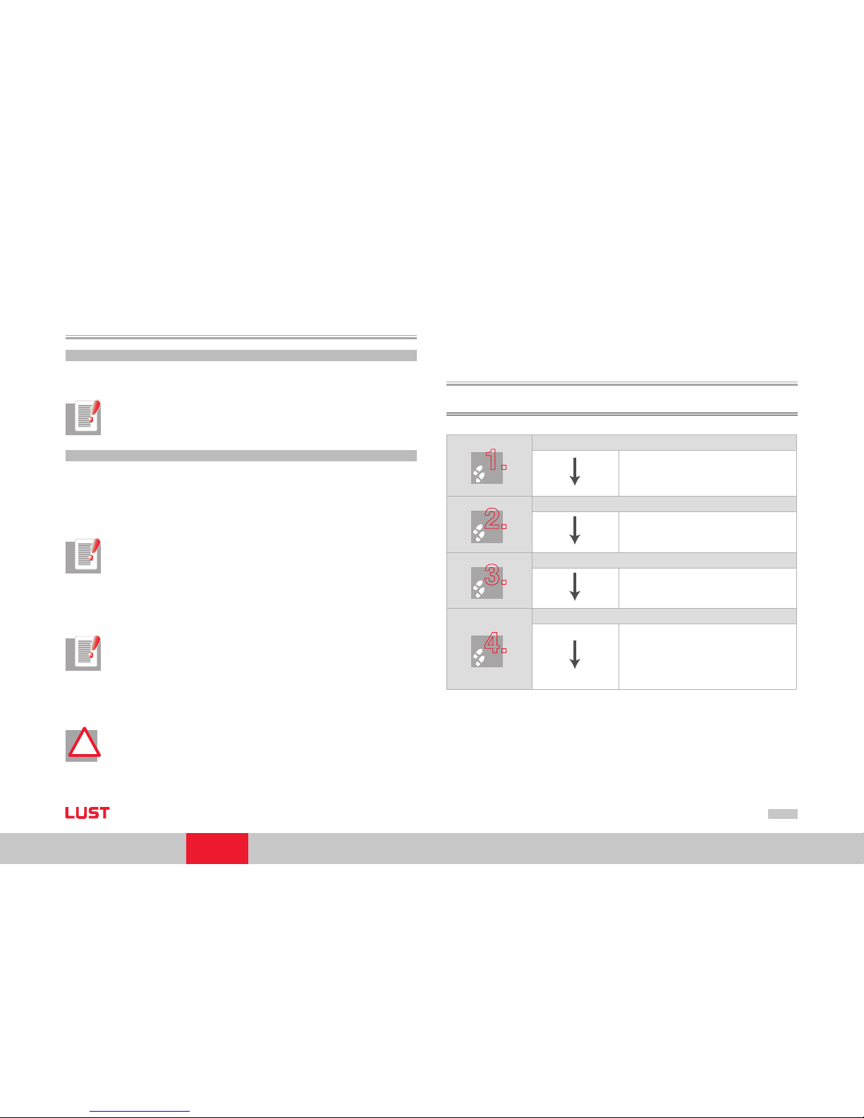
Procedure for commissioning with the aid of the Application Manual
1.
Initial commissioning based on Operation Manual
A precondition for this is initial commissioning
with the aid of the Operation Manual.
The User Manual only covers adjustment of the
software func tions.
2.
Commissioning as per Application Manual
Setting the drive controller parameters using the
Application Manual. This includes, for example,
the configuration of technology functions .
3.
Commissioning based on CANopen User Manual
Configuration of field bus-sp ecific settings
(e. g. Baud rate) using this document.
4.
Checking the set application solution
To preserve the safety of personnel and ma chinery, the application solution should only be
checked at low speed. Make sure the direction
of rotation is correct. In case of emergency the
controller power stage can be disable d, and the
drive stopped, by rem oving the ENPO signal.
Page 22
User Manual CANopen/EtherCAT
22
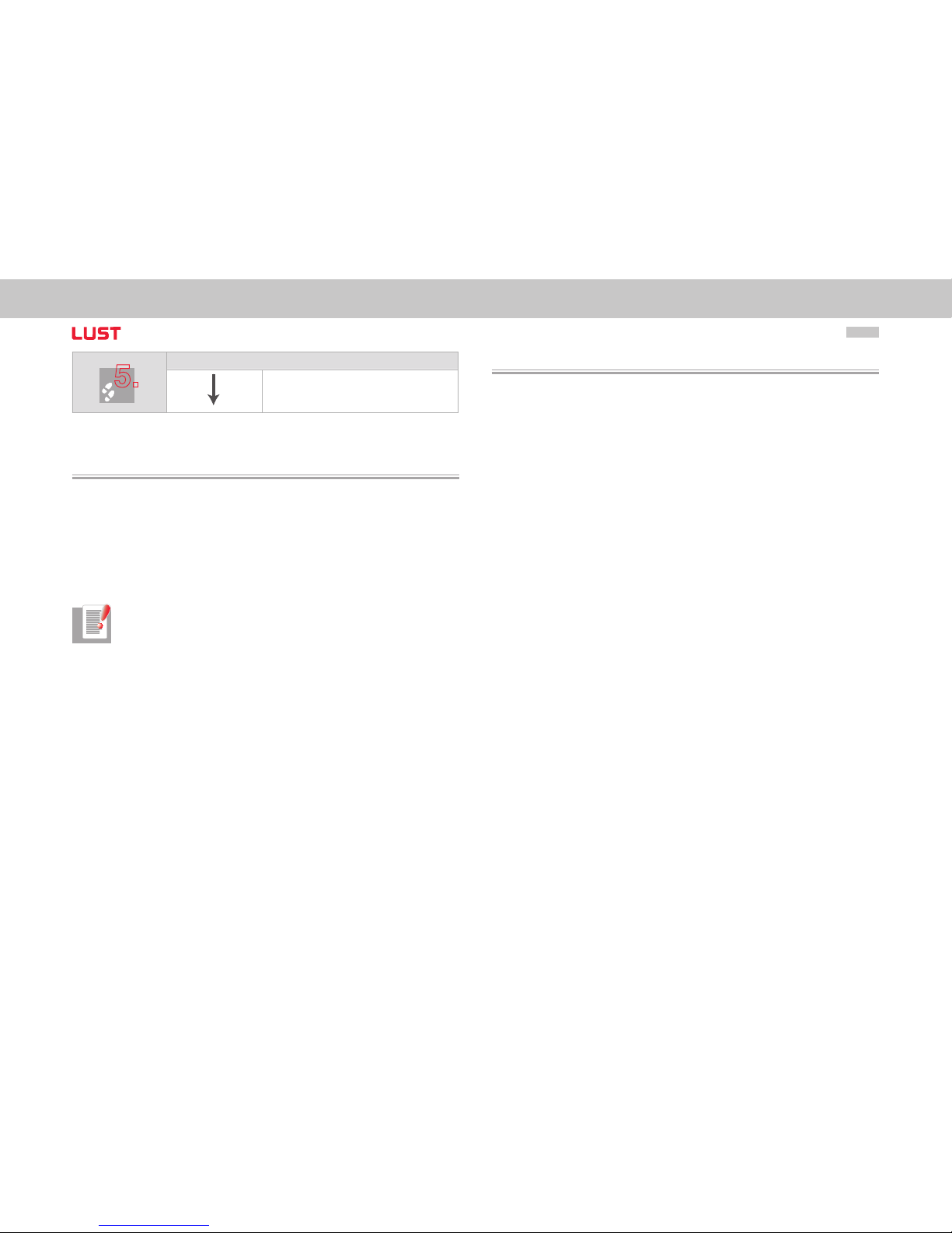
5.
Completing commissioning
When you have successfull y completed commissioning, save your set tings (using DriveManager)
and store the data set in the device.
4.7 Control functions
Control functions can be optimally adapted to the relevant application. Consequently,
several control formats are offered. The appropriate formats can be selected by the master during the setup phase over the bus, or by adjusting the relevant device parameters.
The drive devices‘ state machine has a cycle time of 1 ms.
All control commands and reference values are processed within that cycle time by the
drive device.
Note: Control PDOs are processed in a minimum cycle time of 1 ms. If
protocols arrive at the device faster, the telegram that arrived most recently
overwrites the previous one.
An error message is not generated if telegrams are overwritten as a result
of insufficient cycle time.
4.8 Operation mode selection (Modes of operation)
There are different control modes for operation of the devices via CANopen. The active
operation mode is always selected via DS402 objec t 6060h (Modes of Operation).
ServoOne suppor ts the operation modes as per the DS402:
Profile Position Mode
Profile Velocity Mode
Homing Mode
Interpolated Position Mode
Cyclic Synchronous Position Mode (EtherCAT only)
Cyclic Synchronous Velocity Mode (EtherCAT only)
Cyclic Synchronous Torque Mode (EtherCAT only)
In the course of initial commissioning the user implements the settings of the drive using
motor data, loop control settings, I/O configuration etc.
A relevant control mode is also directly connected with the respective operation mode.
By switching modes of operation via CANopen, it is possible to switch directly between
position control, speed control and torque control.
The drive is thus in speed control for Profile Velocity Mode and in position control for
Profile Position Mode.
–
–
–
–
–
–
–
Page 23
User Manual CANopen/EtherCAT
23
[Chapter 4]
4.8.1 Functionality of operation modes
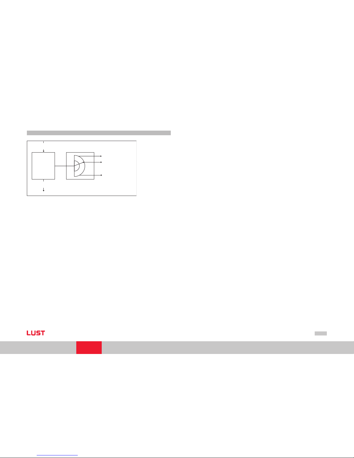
modes_of_operation
(6060h)
modes_of_operation_display
(6061h)
Operation
Mode
Function
Profile Position Mode
Profile Velocity Mode
Homing Mode
Figure Functionality of operation mo des Change modes in the diagram
Users can switch between the various operation modes, as long as these are supported
by the device.
The status word contains bits, the meaning of which depends on the operation mode.
For monitoring, it is necessary for the bits to change their meaning when modes are
switched, see also Chapter 6.
Page 24
User Manual CANopen/EtherCAT
24
Page 25

User Manual CANopen/EtherCAT
25
[Chapter 5]
5 Commissioning and Configura-
tion of EtherCAT
Commissioning via EtherCAT is possible using the XML file supplied on your controller.
All further commissioning and configuration steps are independent of the controller
used. For notes on this refer to the documentation provided by your control manufacturers.
Page 26
User Manual CANopen/EtherCAT
26
Page 27
User Manual CANopen/EtherCAT
27
[Chapter 6]
6 Setting the Device Parameters
for CANopen
6.1 Implemented DS301 functionality
6.1.1 Communication objects
Boot-up to DS301 V4.01 (Guarding boot-up via identifier 700h)
Four variably mappable TxPDOs (transmission type 1 to 240, 254 and 255dec
possible).
Four variably mappable RxPDOs (transmission type 1 to 240, 254 and 255dec
possible).
An SDO server - Pay attention to definition of time conditions (typical processing
time in device approx. 5 ms, depending on capacit y utilisation)
One emergency objec t error code to DS402 plus manufacturer-specific error loca
-
tion and number, operating hours of the device
One Sync object
NMT state machine to DS301
Node guarding and heartbeat (see below)
Processing cycle:
PDO protocols can be processed in a minimum cycle time of 1ms. If protocols
arrive faster, previous protocols are overwritten.
SDO protocols and NMT services are processed acyclically. Typical processing times
lie between 1 and 5 ms.
Initialisation values of the COB IDs based on Predefined Connection Set
Access to device parameters 2000h - 5FFFh (expedited/non-expedited).
•
•
•
•
•
•
•
•
•
•
•
•
6.1.2 Object directory of DS301
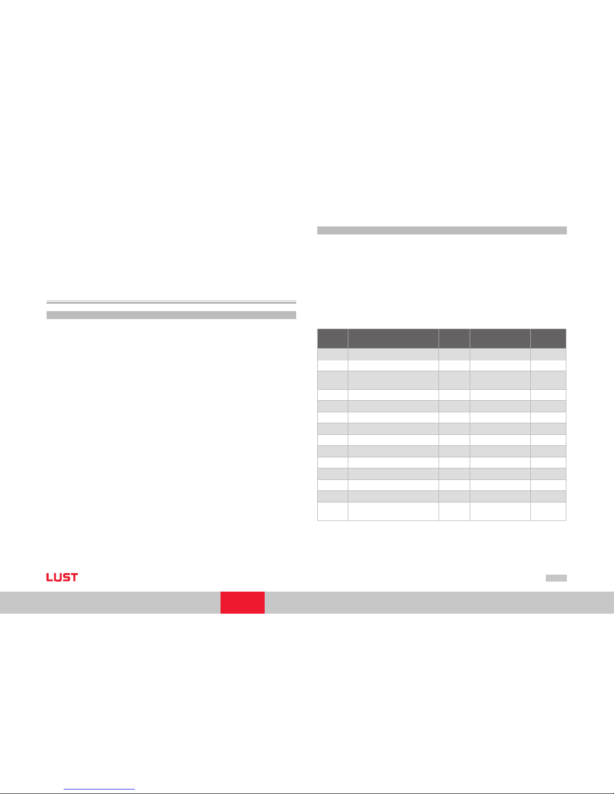
For a full overview of the suppor ted CAN objects of ServoOne refer to the EDS file.
Here you can refer to both the CANopen objects of DS301, DS402 and also the manuf
-
acturer-specific objects of the device.
The following list shows an extrac t of the object directories with important DS301
objects. For these objects the transmission types or mapping, for example, are explained
below.
Object
No.
Object name
Object
Code
Type Attr.
0x1000 Device_Type VAR Unsigned32 ro
0x1001 Error_Register VAR Unsigned8 ro
0x1003
Pre-Defined_Erro r_Field One
subentry
ARRAY Unsigned32 ro
0x1005 COB-ID_ SYNC VAR Unsigned32 rw
0x1006 Communication_Cycle_ Period VAR Unsigned32 rw
0x1007 Synchronous_Window_Length VAR Unsigned32 rw
0x1008 Manufacturer device name String
0x1009 Manufacturer hardware version String
0x100A Manufacturer software ver sion String
0x100C Guard_Time VAR Unsigned16
0x100D Life_Time_Factor VAR Unsigned8
0x1014
COD-ID_ EMCY VAR Unsigned32
0x1017 Producer_Heartb eat_Time VAR Unsigned16 rw
0x1018
Identity_Object suppor t all 4
entries (serial number, etc.)
RECORD Identity (23h) ro
Table Object direc tory
Page 28
User Manual CANopen/EtherCAT
28
Object
No.
Object name
Object
Code
Type Attr.
0x1400 1st_Receive _PDO_ Parameter RECORD PDO CommPar rw
0x1401
2nd_Receive_PDO_ Parameter RECORD PDO CommPar r w
0x1402 3rd_Receive_PDO_ Parameter
RECORD PDO CommPar rw
0x1403 4th_Receive _PDO_ Parameter
RECORD PDO CommPar rw
0x1600
1st_Receive _PDO_ Mapping
max 8 object s
RECORD PDO Mapping (21h) rw
0x1601
2nd_Receive_PDO_ Mapping
max 8 object s
RECORD PDO Mapping rw
0x1602
3rd_Receive_PDO _Mapping
max 8 object s
RECORD PDO Mapping rw
0x1603
4th_Recei ve_PDO _Mapping
max 8 object s
RECORD PDO Mapping rw
0x1800 1st_Transmit_PDO_ Parameter RECORD PDO CommPar (20h) rw
0x1801 2nd_Transmit_PDO_ Parameter RECORD P DO CommPar (20h) rw
0x1802 3rd_Transmit_PDO_Parameter RECORD PDO CommPar rw
0x1803 4th_Transmit_PDO_ Parameter
RECORD PDO CommPar rw
0x1A00
1st_Transmit_PDO_ Mapping
max 8 object s
RECORD PDO Mapping rw
0x1A01
2nd_Transmit_PDO_ Mapping
max 8 object s
RECORD PDO Mapping rw
0x1A02
3rd_Transmit_PDO _Mapping
max 8 object s
RECORD PDO Mapping rw
0x1A03
4th_Transmit_PDO _Mapping
max 8 object s
RECORD PDO Mapping rw
Table Object direc tory
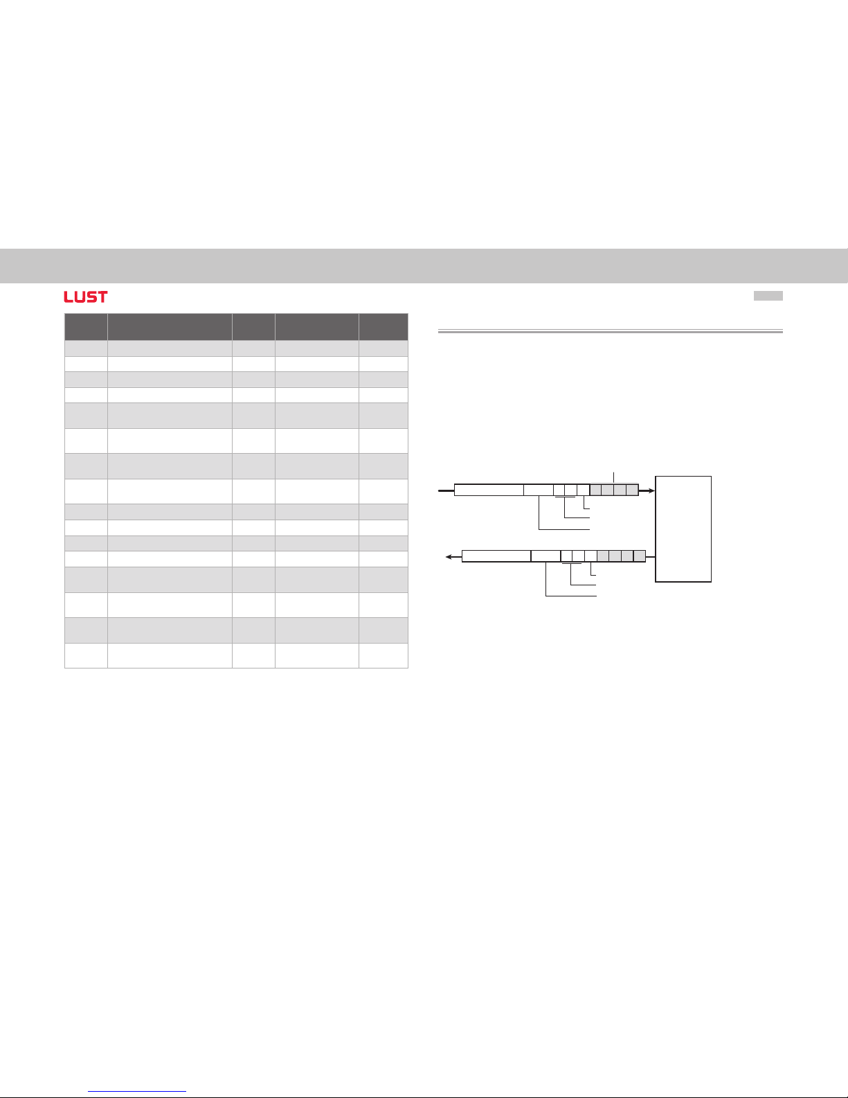
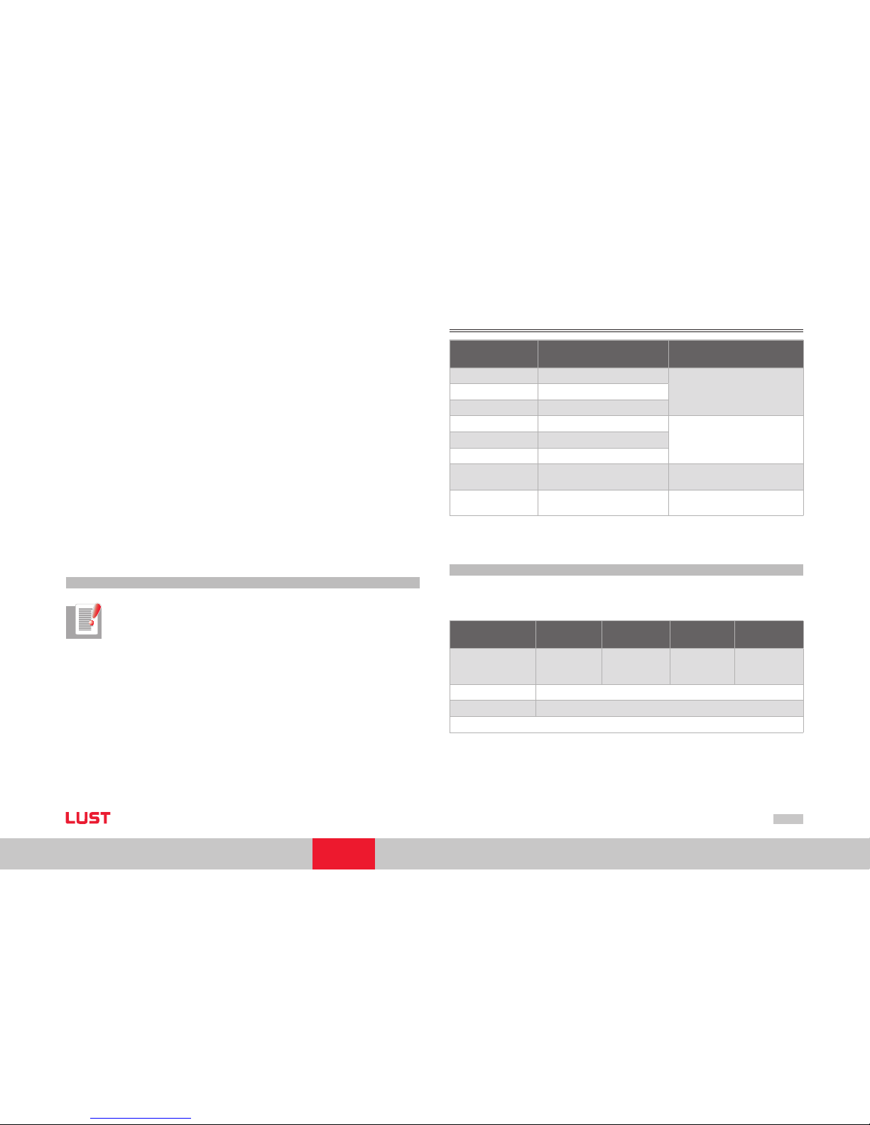
6.2 Parameter channel (Service Data Objects)
The Service Data Object (SDO) permits write and read access to the object directory. This
SDO is implemented according to the CAL specification by the Multiplexed Domain CMS
object. The protocol is designed for the transfer of data of any length. For SDO transfer,
an SDO server is integrated into the device. Communication is by way of two reserved
identifiers.
Receive SDO: 600 h
Transmit SDO: 580 h
SDO-Client
SDO-Server
Object
directory
Drive
controller
600H + Node-ID Byte 0 1 2 3 4 5 6 7
580H + Node-ID Byte 0 1 2 3 4 5 6 7
Subindex
Index
Control field
Subindex
Index
Control field
Data
Figure Example of SDO data transfer in Expedited Mode
Page 29
User Manual CANopen/EtherCAT
29
[Chapter 6]
The CAL specification makes a basic distinction between three protocol services:
Download protocol (Write)
Upload protocol (Read)
Abort protocol (Error)
The upload and download protocols also differentiate between:
Expedited Multiplexed Domain Protocol for access to objects with a data length
of up to 4 bytes (shown above) and
Multiplexed Domain Protocol, for access to objects of any length
The entries in the “Control field“ area are generated by the CANopen driver. They are
only included to fully document the examples cited. The entries are dependent on the
transferred data.
The control field is described in the DS301 profile.
6.2.1 Data types
Note: Via the DriveManager user interface many parameter settings are
displayed in the form of value substitution texts.
Example: Parameter 450-MOT_Type = PSM
When writing and reading over the field bus the corresponding numerical values for these value substitution texts must be used. These values are displayed in brackets ( ) when
the parameter is opened in DriveManager.
Example:
Parameter 450-MOT_Type = PSM (1)
•
•
•
•
•
The drive units support the following parameter data formats:
Data type Value range Function
USIGN8 0...255
UnsignedUSIGN16 0...65535
USIGN32 0...4294967295
INT8 -128...127
Integer, signedINT16 -32768...32767
INT32 -2147483648...2147483647
FLOAT32
see IEEE
32-bit floating point number in I EEE
format
STRING
ASCII character s, max. 100 bytes
in bus mode incl. zero terminator
Table Data types
6.2.2 Representation of data types in the control protocol
All data types are represented appropriate to their preceding sign as 32-bit variables
in Intel format.
Data bytes of the
control protocol
3 4 5 6
USIGN8/ INT8*
USIGN16/INT16*
USIGN32/INT32
Low Word
Low Byte
Low Word
High Byte
High Word
Low Byte
High Word
High Byte
FLOAT32
IEEE format
STRING See e xamples,
* Filled out appropriate to preceding sign (00H or FFH)
Table Assignment of data types in the data field
Page 30
User Manual CANopen/EtherCAT
30
6.2.3 Access to device parameters
Where can I find the device parameters?
All device parameters are addressed by way of a parameter number.
In addition to the standard objects, the CANopen profile provides an area for manufacturer-specific entries. This area lies between 2000 h and 5FFF h. If you then want to read
or write parameter 455-MOT_FNOM (rated frequency of the motor) of the device, the
object index is formed from 200 0 h + parameter number (Hex).
In our example: Index = 2000 h + 1C7 H
Note: Profile-specific parameters are visible in DriveManager, but only in area
1000H... (DS301 objects)/6000H... (DS402 objects) writeable/readable. This
means parameters stored both as device parameters (area 2xxxH) and also as
profile parameters (DS301/DS402), can only be read and written to via their
object number (DS301/DS402 profile).
Example:
The object 1000h Device Type exists both in the DS301 profile and also as a device
parameter with parameter number 2011. Simultaneous two-way access would therefore be possible via CANopen or EtherCAT. In order to clearly configure the access, the
read/write access for this object is only possible via profile -specific object number 1000h
(as per DS301).
6.3 Examples of SDO handling
By way of the Receive SDO (COB IDs: 600 h + Node-ID) the CANopen objects and the
parameters of the drive controller can be accessed.
In a data transfer protocol a maximum of 4 data bytes can be transferred in Expedited
mode. This means all device parameters, apart from string parameters, can be written
to with a single transfer protocol.
String parameters can be written to using the Multiplexed Domain protocol.
Page 31

User Manual CANopen/EtherCAT
31
[Chapter 6]
Example of read access to string parameters (parameter 3 DV_DeviceAliasName)
Note:
- All numeric values are hexadecimal
- The string “X-axis“ is to be transferred
- This text is entered in ServoOne parameter 3 DV_DeviceAliasName
TIME ID Direction DLC Byte 0 Byte 1 Byte 2 Byte 3 Byte 4 Byte 5 Byte 6 Byte 7 Comments
18.992445 Tx 601 8 40 03 20 00 0 0 0 0 0 0 0 0 Read o bject 2003h (= parameter 3)
18.992972 Rx 581 8 41 03 20 00 64 00 00 00 Reply : 64h --> 100by tes to be transferred
35.514341
Tx 601 8 60 00 00 0 0 0 0 0 0 0 0 0 0 Requirement Segment 1
35.514594
Rx 581 8 00 58 2d 41 78 69 73 00 Reply S egment 1 - contains “X-axis“
36.269620
Tx 601 8 70 00 00 0 0 0 0 0 0 0 0 0 0 Requirement Segment 2
36.270175
Rx 581 8 10 00 00 00 00 00 00 00 Reply S egment 2
36.982385
Tx 601 8 60 00 00 0 0 0 0 0 0 0 0 0 0 Requirement Segment 3
36.982664
Rx 581 8 00 00 00 00 00 00 00 00 Reply S egment 3
37.686447
Tx 601 8 70 00 00 0 0 0 0 0 0 0 0 0 0 Requirement Segment 4
37.686706
Rx 581 8 10 00 00 00 00 00 00 00 Reply S egment 4
38.421344
Tx 601 8 60 00 00 0 0 0 0 0 0 0 0 0 0 Requirement Segment 5
38.421604
Rx 581 8 00 00 00 00 00 00 00 00 Reply S egment 5
39.053526
Tx 601 8 70 00 00 0 0 0 0 0 0 0 0 0 0 Requirement Segment 6
39.053787
Rx 581 8 10 00 00 00 00 00 00 00 Reply S egment 6
39.749081
Tx 601 8 60 00 00 0 0 0 0 0 0 0 0 0 0 Requirement Segment 7
39.749347
Rx 581 8 00 00 00 00 00 00 00 00 Reply S egment 7
40.428981
Tx 601 8 70 00 00 0 0 0 0 0 0 0 0 0 0 Requirement Segment 8
40.429249
Rx 581 8 10 00 00 00 00 00 00 00 Reply S egment 8
41.085839
Tx 601 8 60 00 00 0 0 0 0 0 0 0 0 0 0 Requirement Segment 9
41.086198
Rx 581 8 00 00 00 00 00 00 00 00 Reply S egment 9
Page 32

User Manual CANopen/EtherCAT
32
TIME ID Direction DLC Byte 0 Byte 1 Byte 2 Byte 3 Byte 4 Byte 5 Byte 6 Byte 7 Comments
41.740755 Tx 601 8 70 00 00 00 00 00 00 00 Requirement Segment 10
41.741148
Rx 581 8 10 0 0 0 0 0 0 0 0 00 00 00 Reply Segment 10
42.514034
Tx 601 8 6 0 0 0 0 0 0 0 0 0 0 0 0 0 0 0 Requirement Segment 11
42.514294
Rx 581 8 00 0 0 0 0 0 0 0 0 00 00 00 Reply Segment 11
43.172512
Tx 601 8 70 00 00 0 0 0 0 0 0 0 0 0 0 Re quirement Segment 12
43.172787
Rx 581 8 10 0 0 0 0 0 0 0 0 00 00 00 Reply Segment 12
43.908571
Tx 601 8 6 0 0 0 0 0 0 0 0 0 0 0 0 0 0 0 Requirement Segment 13
43.908831
Rx 581 8 00 0 0 0 0 0 0 0 0 00 00 00 Reply Segment 13
44.668 466
Tx 601 8 70 00 00 0 0 0 0 0 0 0 0 0 0 Re quirement Segment 14
44.668740
Rx 581 8 10 0 0 0 0 0 0 0 0 00 00 00 Reply Segment 14
53.8840 44
Tx 601 8 6 0 0 0 0 0 0 0 0 0 0 0 0 0 0 0 Requirement Segment 15
53.884414
Rx 581 8 0b 0 0 0 0 0 0 0 0 00 00 00 Reply Segment 15 - No further segments
Translation of transferred values (ASCII):
The string “X-Axis“ at 6 bytes is so short that it can be completely transferred with the
first segment.
The following segments (of 100 bytes of parameter) therefore only include zeroes.
Transmitted bytes (HEX) 58 2d 41 78 69 73
Interpretation (ASCII) X - A x i s
Page 33

User Manual CANopen/EtherCAT
33
[Chapter 6]
6.3.1 Parameter set download
The following data can be transferred to Ser voOne via the CANopen interface:
Parameter set
A parameter data set can be downloaded by an SDO transfer or by way of the
DriveManager user interface version 5 or higher. All manufacturer-specific device
parameters are additionally accessible via objects 2000h- 5FFFh.
If a unified valid data set - that is, not just individual parameters - needs to be transferred
from the CAN master to the device, the following points must be considered:
On every transfer of an individual parameter the drive controller checks whether the
parameter matches its existing data set. The check of the new parameter value includes
existing parameter values in some cases. This means it is possible that the drive controller may reject a parameter, even though it originates from a valid parameter data set,
because the parameter is not yet complete in the device.
Since a simple error reset may not eliminate the cause of the error, it may be necessary
to reset to the factory defaults.
Remedy:
The parameter data set is transferred to the drive controller without a logic check. At the
end of the download, the logic check is reactivated and the drive controller checks the
transferred parameters for plausibility. During this check parameter settings that do not
functionally match are reported as errors.
Download procedure of a completed parameter data set:
•
•
Reporting a download without logic check
To deactivate the logic check and to report the download of a data set, parameter
11 subindex 4 value 1 is written.
Downloading the parameter data to the drive controller
In this step the individual parameters of the data set are sequentially transferred
to the drive. Despite the deactivated logic check basic checking mechanisms are
still active. These monitor, for example, the maintenance of parameter limits and
become active if these are infringed. Thus if a value range limit is infringed by
the download of a parameter, then this SDO protocol is directly rejected (Abort
message).
Completing download and activating plausibility check
Once all parameter data has been transferred to the drive controller, parameter
11 subindex 4 is reset to value 0. Then a logic check of the device parameters is
carried out. In cases of error the user receives an Emergency message.
Note: The download of a complete parameter data set is only possible when
the system is at a standstill. Make sure the drive controller is not switched on
for the duration of the download.
1.
2.
3.
Page 34
User Manual CANopen/EtherCAT
34
6.4 PDO transmission types
In connection with the PDO transfer, various transmission types are defined in CANopen
profile DS301. The transmission type and event control can be set separately for all sup
ported RXPDOs and TXPDOs. The drive controller suppor ts the following transmission
types:
Cyclic Synchronous Types No. 1-F0 h
Meaning: The difference between this and the acyclic synchronous transmission type is
that RXPDOs are only evaluated after receipt of 1-F0 h Sync objects and TxPDOs are only
transmitted every 1-F0 h Sync objects.
Asynchronous Types No. FE h and FF h
Meaning: RxPDOs are evaluated immediately on receipt; TxPDOs are transmitted by a device-specific event. The Sync object is irrelevant to this mode of transfer. Special feature
type FF h:
In this case the event is defined in the associated device profile.
Note: The desired transmission types are set by way of the corresponding
CANopen objec ts 1400h for RxPDOs and 1800h for TxPDOs.
6.5 Event-controlled TxPDO transmission
Note: Event control is only active when the relevant “transmission type“
is set to asynchronous (FEh or FFh).
Functions of event control:
Any bit changes within the TxPDO can serve as an event for the sending of a TxPDO.
Thus only the mapped contents of this TXPDO are relevant as an event for the sending
of a TxPDO. Accordingly it is not possible to send a TxPDO dependent on the changes to
the content of another TxPDO.
Example:
The status word 6041h is mapped in TxPDO1. TxPDO2 contains the current actual posi
tion. A change to the status word in TxPDO1 can therefore not be used as an event for
the sending of the TxPDO2. If this is required, however, the status word 6041h can also
be mapped in TxPDO2.
Selecting the events:
In ServoOne ever y bit (or a change to it) in a TxPDO can be defined as an event. By default all bits (max. 64bit = 8byte) are monitored for changes and are evaluated as events.
Individual bits can be displayed via screens, however, and therefore are no longer used
for event generation.
There are screens defined in field parameter 2007 enabling the display of individual bits
of TxPDOs. Subindexes are respectively relevant for a TxPDO. Each subindex is responsible for 32 bits of the TxPDO. The structure is thus as follows:
Page 35
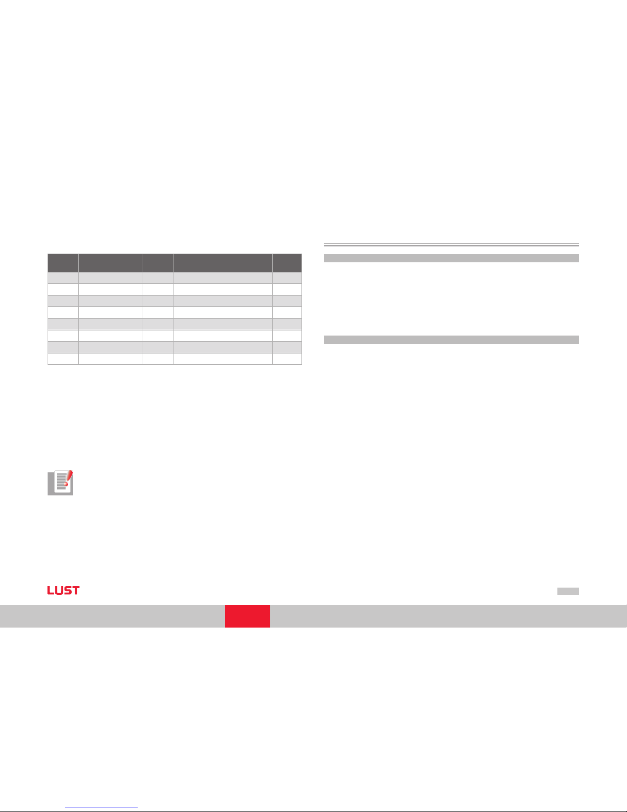
User Manual CANopen/EtherCAT
35
[Chapter 6]
Parameter 2007 - COM _301_EvMask
“Event mask for asynchronous transmit pdos“
Sub
Id
Name Value Description Type
0 EvMsk_TxPdo1L FFFFFFFFh Eve nt mask for txpdo 1 by te 0-3 uint32
1 EvMsk_TxPdo1H FFFFFFFFh Event mask for tx pdo 1 byte 4- 8 uint32
2 EvMsk_TxPdo2L FFFFFFFFh Eve nt mask for txpdo 2 by te 0-3 uint32
3 EvMsk_TxPdo2H FFFFFFFFh Event mask for tx pdo 2 byte 4- 8 uint32
4 EvMsk_TxPdo3L FFFFFFFFh Eve nt mask for txpdo 3 by te 0-3 uint32
5 EvMsk_TxPdo3H FFFFFFFFh Event mask for tx pdo 3 byte 4- 8 uint32
6 EvMsk_TxPdo4L FFFFFFFFh Eve nt mask for txpdo 4 by te 0-3 uint32
7 EvMsk_TxPdo4H FFFFFFFFh Event mask for tx pdo 4 byte 4- 8 uint32
Table Field parameter 2007
Example of application of screens:
To only allow the lower 16 bits of the TxPDO1 as an event, the subindexes of parameter
2007 are described as follows:
Subindex 0 (Event screen TxPDO1 bytes 0 – 3) = 0000FFFFh
Subindex 1 (Event screen TxPDO1 bytes 4 – 7) = 0000 0000h
Note: The cyclic sending of the Tx PDOs is activated by setting a cycle time
in ms in the objects 0x1800 (TxPDO1) 0x1801(TxPDO2), 0x1802 (TxPDO3)
and 0x1803 (TxPDO4) subindex 5 (event timer).
–
–
6.6 PDO mapping
6.6.1 Mapping - general
Variable mapping of parameters is possible on ServoOne for all 4 Rx and TxPDOs.
Mapping works as defined in the CANopen communication profile DS301.
Most device-specific parameters form part of the manufacturer-specific area (2001h5FFFh) and can also be mapped in the PDOs. For these parameters (objects), refer to the
EDS file of the drive controller.
6.6.2 Mapping notes
In contrast to earlier devices ServoOne no longer has predefined mapping or mapping
selectors. This means that prior to communication via PDO the mapping must be writ ten
to the drive controller by the controller. Transfer of the data set is also possible.
By default all mapping settings are set to 0, i. e. the PDOs do not contain any mapping.
The communication settings (mapping/transmission types etc.) can be saved in the
device however, and are subject to data set handling. This means they must be rewritten
each time and can be transferred with the data set.
The following objects are relevant for mapping:
RxPDOs:
1600h RxPDO1 mapping
1601h RxPDO2 mapping
1602h RxPDO3 mapping
1603h RxPDO4 mapping
TxPDOs:
1A00h TxPDO1 mapping
1A01h TxPDO2 mapping
1A02h TxPDO3 mapping
1A03h TxPDO4 mapping
Page 36
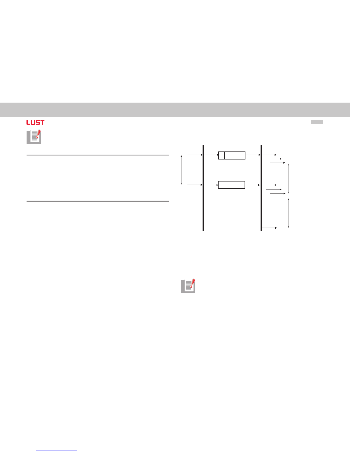
User Manual CANopen/EtherCAT
36
Notes: A maximum of 8 objects can be mapped per PDO.
In a PDO a maximum of 8 bytes can be mapped.
6.7 Heartbeat function
The Heartbeat function to DS301 (V4.01) is supported. Ser voOne can only be used as
heartbeat producer, i.e. it sends heartbeat telegrams to the controller. To this end object
1017H Producer Heartbeat Time is implemented.
A time value (in ms) is entered as a value for this object. The time value represents the
cyclic interval during which the drive controller sends its heartbeat telegrams.
Heartbeat protocol
The Heartbeat protocol defines an ERROR CONTROL SERVICE without using REMOTE
FRAMES.
A HEARTBEAT PRODUCER sends a cyclic HEARTBEAT MESSAGE. One or more HEARTBEAT CONSUMERS receive this message. The relationship bet ween the PRODUCER and
the CONSUMER can be configured by way of the objects described below. The HEARTBEAT CONSUMER monitors receipt of the HEARTBEAT PROTOCOL taking account of the
preset HEARTBEAT CONSUMER TIME.
If the HEARTBEAT PROTOCOL is not received within the HEARTBEAT CONSUMER TIME,
a HEARTBEAT event is generated.
The HEARTBEAT PROTOCOL starts directly after entry of the HEARTBEAT PRODUCER
TIME.
If the device is powered up with a HEARTBEAT PRODUCER TIME setting not equal to 0,
the HEARTBE AT PROTOCOL starts with the state transition INITIALISING -> PREOPERATIONAL.
In this case the BOOTUP MESSAGE is classed as the first HEARTBEAT MESSAGE.
7
r
6 .. 9
s
0 1
7
r
6 .. 9
s
0 1
Heartbeat
Producer
request
Heartbeat
Producer
Time
request
Write Heartbeat
COB-ID = 700 + Node-ID
Heartbeat
Consumer
indication
indication
indication
indication
indication
indication
Heartbeat
Consumer
Time
Heartbeat
Consumer
Time
Heartbeat Event
Figure Heart beat protocol
r: reserved (always 0)
s: the state of the Heartbeat producer
0: BOOTUP
4: STOPPED
5: OPERATIONAL
127: PRE-OPER ATIONAL
The NODE GUARDING and HEARTBEAT functions cannot be used in a device
simultaneously. If the HEARTBEAT PRODUCER TIME is not equal to 0, the
HEARTBEAT PROTOCOL is used.
Page 37
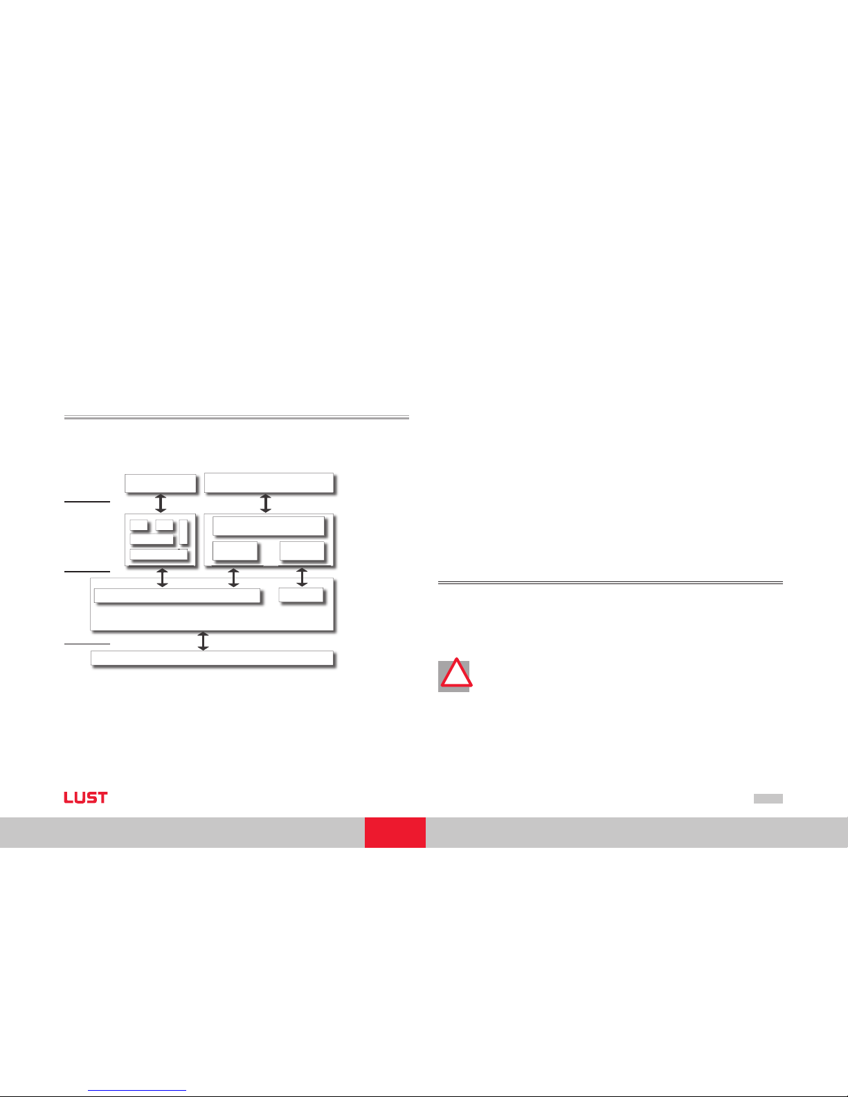
User Manual CANopen/EtherCAT
37
[Chapter 7]
7 Setting the Device Parameters
for EtherCAT
7.1 Supported EtherCAT functionality
Below you will find an overview of the EtherCAT functionality implemented in ServoOne.
The next diagram shows the basis for the following description. It shows the struc ture of
EtherCAT based on the OSI 7 layer model.
Physical Layer
EtherCAT Data Link Layer
Process Data
Emergency / SDO /
SDO Information Service
Mailbox
EoE
SDO PDO Mapping
Object Dictionary
Ethernet
IP
TCP
UDP
HTTP, FTP ...
Application
(DSP402 profile)
(Ethernet)
AL
DL
Figure Structure Ether CAT
The physical layer of EtherCAT based on IEEE802.3/100 BaseTX Ethernet physics. Based
on this the EtherCAT Data Link Layer (DL) follows, which is split into mailbox and process
data. The following layer is termed as AL (Application Layer) and includes the ser vices of
CoE (CAN over EtherCAT) and EoE (Ethernet over EtherCAT).
All services that are not time-critical, i. e. their execution/contents do not critically intervene in process data in terms of time, are grouped together in the mailbox. The mailbox
is used as a service data channel and thus also enables access to drive parameters. This is
done via the SDO (Service Data Objects) channel. The mailbox ser vice also provides the
basis for the services of EoE (Ethernet over EtherCAT) and the error handling (emergency
telegrams).
The process data is designed on the basis of CANopen (CiA DS301). This means there is
mapping of objects in PDOs (Process Data Objects) that are cyclically transferred. This
process data includes, for example, cyclic position, speed or torque reference values and
actual values.
The basis for both SDO and PDO accesses to the drive is always the object directory,
which is realised based on CANopen. For the user this means that these objects can be
accessed both via CANopen and via EtherCAT.
In the case of ServoOne the DS402 profile is again set up on the application layer.
For information on this layer refer to the sections “Implemented DS402 functionality“
and “DS402 operation modes“.
An overview of the EtherCAT functionality of ServoOne is provided below:
Process Data
4 RxPDOs
4 TxPDOs
Transfer length = max. 8 bytes per PDO
Variable mapping as per DS301 (cf. CANopen)
Attention: The PDO must have an even number of bytes assigned. If an
uneven number is required, this must be filled up with a “Dummy Byte“ for
example...
Cycle times
Transfer cyclic position references with max. 8 kHz (125µs)
Transfer cyclic speed reference with max. 8 kHz (125µs)
Transfer cyclic torque references with max. 8 kHz (125µs)
•
•
•
•
•
!!
Page 38
User Manual CANopen/EtherCAT
38
Mailbox
ServoOne suppor ts the CAN over EtherCAT (CoE) and Ethernet over EtherCAT (EoE)
protocol. The following functions/services are implemented:
CoE
Sdo/Abort
Initiate SDO Download
Download SDO Segment
Initiate SDO Upload
Upload SDO Segment
Abort SDO Transfer
All device parameters are accessible via object ID 2000H + x
Note: Profile-specific parameters are visible in DriveManager, but only in
range 1000H... (DS301 objects)/6000H... (DS402 objects) writeable/readable.
This means parameters stored both as device parameters (range 2xxxH) and
also as profile parameters (DS301/DS402) can only be read and written to via
their object number (DS301/DS402 profile).
Example:
The object 1000h Device Type exists both in the DS301 profile and also as device pa
rameters with parameter number 2011. Simultaneous two-way access would therefore
be possible via CANopen or EtherCAT. In order to uniquely configure the access, the
read/write-access for this object is only possible via profile-specific object number 1000h
(as per DS301).
•
–
–
–
–
–
–
Emergency
The Emergency service is designed for the transfer of error messages. In contrast to
CANopen, emergency messages in EtherCAT are not autonomously sent from the slave
but are retrieved by the master.
Functionality in ServoOne:
ErrorCodes as per the DS402 device profile are supported.
For the structure/content of the emergency message refer to the section “Emergency Objects“
SDO Information Service
The SDO Information Service allows the master to read the object direc tory of the
slave. In this way, the master can determine the supported objects of the slave with the
required additional information (e. g. data type/access rights etc.). The SDO Information
Service therefore represents an alternative in the use of EDS files known to CANopen.
Functionality in ServoOne:
Access to the object list and description
Alternatives for integrating the EDS file
EoE
Functions such as the tunnelling of standard Ethernet frames in EtherCAT generally fall
under Ethernet over EtherCAT. This enables protocols, for example TCP/IP to be transferred via EtherCAT.
Implemented functionality in ServoOne:
Initiate EoE request
Initiate EoE response
EoE fragment request
EoE fragment response
•
•
•
•
•
•
•
•
Page 39
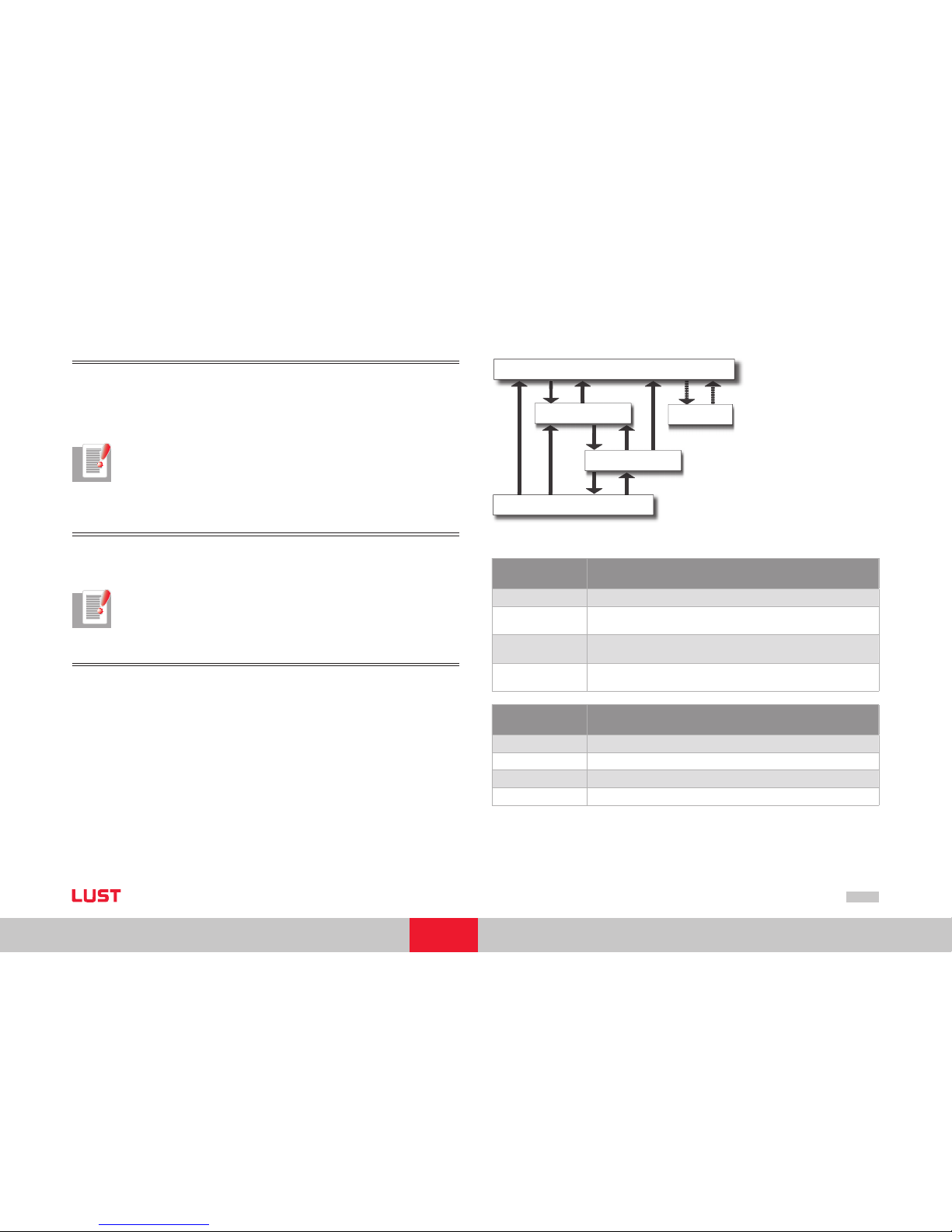
User Manual CANopen/EtherCAT
39
[Chapter 7]
Distributed clocks
Synchronization in the case of EtherCAT is implemented on the basis of distributed clocks. Each slave has its own clock, which is synchronized with the others using a synchronisation pulse. The reference clock with which users are synchronized is accommodated
in a slave.
Notes on ServoOne:
The complete configuration of distributed clocks takes place in the controller.
Multiples of 125µs (time basis of the control) must always be used as cycle
times.
XML file
The XML file helps to integrate an EtherCAT slave into an EtherCAT master (control).
It includes the configuration (mapping etc.) for the respective operation modes.
Notes on ServoOne:
The XML file is provided with the firmware.
The integration of this file is control-specific....
NMT (Network Management)
The Network Management is essentially based on the network management of CANopen. The Stopped (CANopen) state was replaced by the Safe Operational (EtherCAT)
state however.
Depending on the scope of functions of the control software, individual state transitions
can be executed automatically or via the PLC.
Init
Pre-Operational
Safe-Operational
Bootstrap
Operational
(IP) (PI) (IB) (BI)
(SI)
(PS) (SP)
(SO) (OS)
(OI)
(OP)
(optional)
Figure EtherCAT state machine
State Description
Init Initialisation, the device starts up.
Pre-Operational
The device is ready to be configured.
Mailbox communication is p ossible.
Safe-Operational
PDO input data (TxPDO device) can be read.
PDO output data (R xPDO device is ignored.
Operational
Cyclic I/O communication
PDO output data (R xPDO device) is processed.
Transitions Actions
IP Start Mailbox Communication
PI Stop Mailbox Communication
PS Start Input Update
SP Stop Input Update
Table State transitions
Page 40
User Manual CANopen/EtherCAT
40
Transitions Actions
SO Start Output Update
OS Stop Output Update
OP Stop Output Update/ Stop Input Update
SI Stop Input Update/Stop Mailbox Communication
OI Stop Output Update /Stop Input Update /Stop Mailbox Communicati on
Table State transitions
7.2 Configuration for the operation in a controller
The services described in the previous section (e. g. PDO mapping etc.) are all operated
by the controller (EtherCAT master). The communication-specific parameter setting of
ServoOne is per formed on the basis of the supplied XML files by the Master.
The parameter setting of control settings, scaling etc. can also be performed via the
DriveManager. Alternatively all parameters can also be configured via the object directory.
Page 41
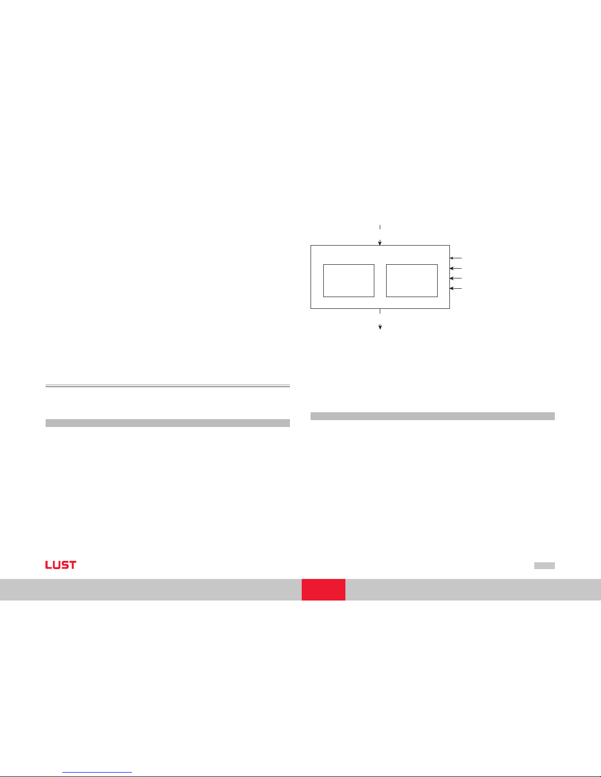
User Manual CANopen/EtherCAT
41
[Chapter 8]
8 Implemented
DS402 Functionality
The functions in this section relate to activation in the modes of operation of DS402
profile
1 - Profile Position Mode
3 -
Profile Velocity Mode
6 - Homing Mode
7 - Interpolated Position Mode
8 - Cyclic Synchronous Position Mode (only EtherCAT)
9 - Cyclic Synchronous Velocity Mode (only EtherCAT)
10 - Cyclic Synchronous Torque Mode (only EtherCAT)
8.1 Device control and state machine
The drive is controlled by way of the DRIVECOM state machine defined in DS402
(see DS402 10.1.1 state machine). No remote signal is planned.
8.1.1 General information
The DEVICE CONTROL FUNCTION monitors all the functions of the controller. This function is subdivided into
device control of the state machine
operation mode function
–
–
controlword
(6040h)
statusword
(6041h)
Remote
Terminals
Fault
modes of operation
(6060h)
Device Controlling
Operation Mode
State Machine
Figure Device controlling
The status of the controller is controlled by way of the control word. The status of the
controller is displayed in the STATUS WORD. In REMOTE MODE the controller is controlled directly from the CANopen network by PDO and SDO.
The state machine is controlled by the control word. The state machine is also influenced
by internal events, such as errors.
8.1.2 State machine
The state machine describes the CONTROLLER STATUS and the possible options for control by the master. A single status indicates a specific internal or external response. At the
same time, the status of a controller restrict s the possible control commands. For exa
mple, initiating a point-to-point positioning operation is only possible in the OPERATION
ENABLE state.
States may change because of the control word or other internal events. The current
status is displayed in the STATUS WORD. The state machine describes the state of the
controller with regard to user commands and internal error messages.
Page 42
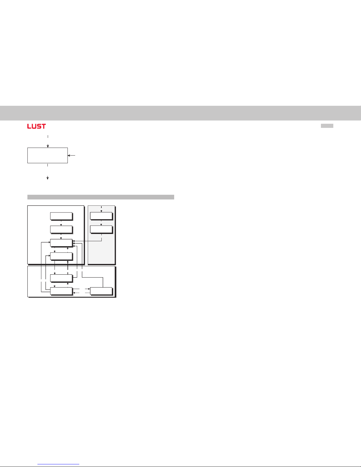
User Manual CANopen/EtherCAT
42
controlword
(6040h)
statusword
(6041h)
Actions
Internal
Events
State Machine
Figure State machine
8.1.3 Device states
Fault
Not Ready to
Switch On
Start
Switch On
Disabled
Ready to
Switch On
Switched On
Operation
Enable
Quick Stop
Activ
Fault
Reaction Active
Fault
Power
Disabled
Power
Ensabled
0
1
2
7
3
6
4
5
11
16
13
14
15
12
10
9 8
Figure State machine
The following device states are possible:
NOT READY TO SWITCH ON:
Only control voltage is connected to the drive.
The drive is initialised or is performing a self-test.
If installed, the brake engages in this state.
The drive function is deactivated.
SWITCH ON DISABLED: (Switch-on inhibit)
Drive initialisation is complete.
Drive parameters have been set.
Drive parameters have been changed.
No power to device (for safety reasons).
The drive function is deactivated.
“STO (Safe Torque Off)“ Standstill and/or ENPO not active.
READY TO SWITCH ON:
Power is connected to the device.
Drive parameters have been changed.
Drive function is deactivated.
SWITCHED ON:
Power is connected to the device.
POWER AMPLIFIER is ready.
Drive parameters have been changed.
The drive function is deactivated.
OPERATION ENABLE:
No errors were detected.
Drive function is enabled and power is connected to motor.
Drive parameters have been changed.
(Relates to standard application of the drive.)
QUICK STOP ACTIVE:
Drive parameters have been changed.
QUICK STOP function being executed.
Drive function is enabled and power is connected to motor.
If the QUICK STOP OPTION CODE is set to 5 (remain at
Page 43
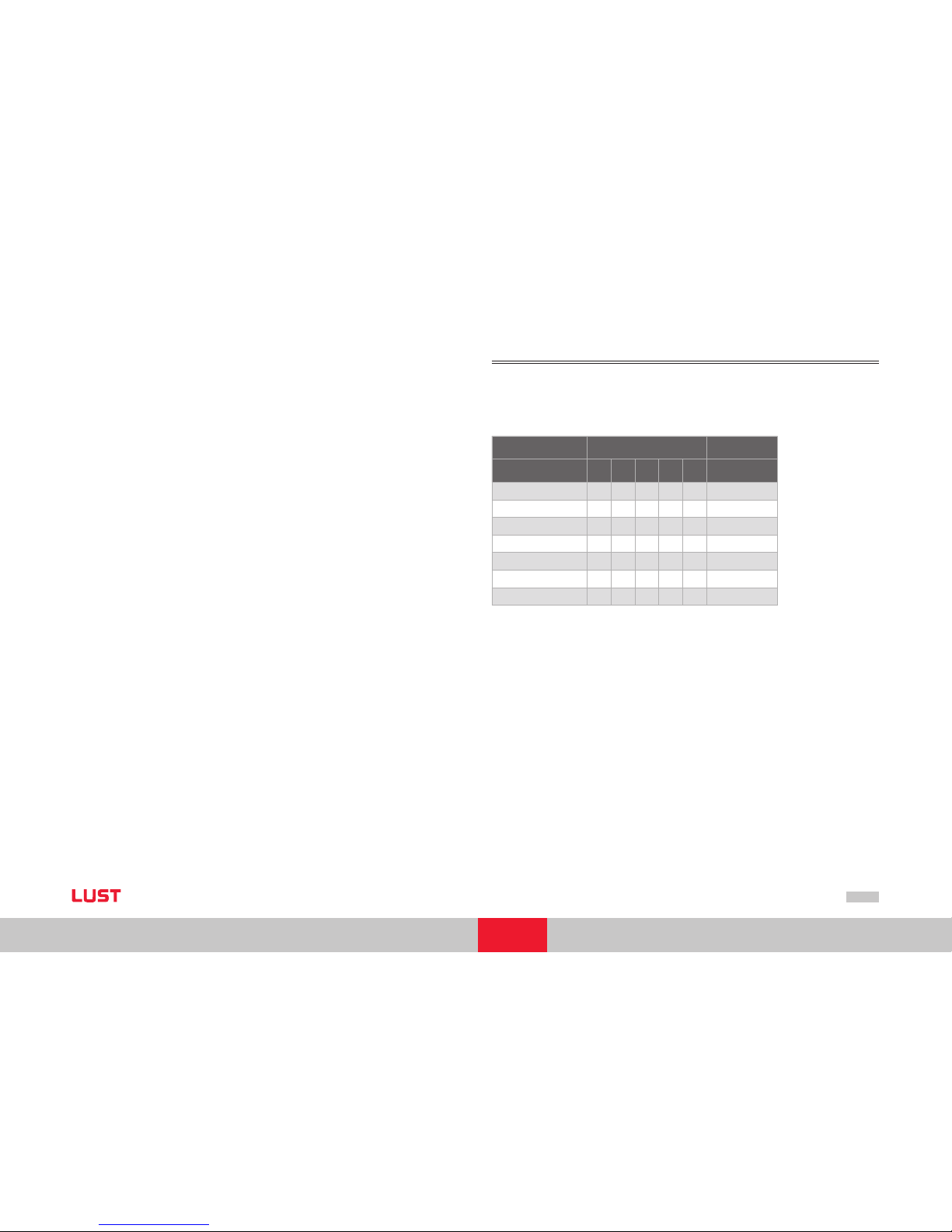
User Manual CANopen/EtherCAT
43
[Chapter 8]
QUICK STOP ACTIVE status), you cannot quit the QUICK STOP
ACTIVE status, but you can switch to OPERATION ENABLE status
with the ENABLE OPERATION command.
FAULT REACTION ACTIVE:
Drive parameters have been changed.
An error has occurred.
The QUICK STOP function has been executed.
Drive function is enabled and power is connected to motor.
FAULT:
Drive parameters have been changed.
An error has occurred, the error response has been executed.
Power disconnection and connection depends on the application.
The drive function is deactivated.
Bit combinations of the DRIVECOM state machine
Device control commands
The following bit combinations of control bits 0-3 and 7 form the device control commands for the state transitions of the state machine:
Control word
Command 7 3 2 1 0 Transitions
SHUTDOWN 0 X 1 1 0 2, 6, 8
POWER-UP 0 X 1 1 1 3
DISABLE P OWER 0 X X 0 X 7, 9, 10, 12
QUICK STOP 0 X 0 1 X 11
DISABLE OPERATION 0 0 1 1 1 5
ENABLE OPERATION 0 1 1 1 1 4
RESET FAULT 0>1 X X X X 15
Page 44
User Manual CANopen/EtherCAT
44
Device status table
The bits of the DRIVECOM status word presented below indicate the current system
state:
Status bit
State 6 5 3 2 1 0
NOT READY 0 X 0 0 0 0
SWITCH- ON INHIBIT 1 X 0 0 0 0
READY 0 1 0 0 0 1
ON 0 1 0 0 1 1
OPERATION ENABLED 0 1 0 1 1 1
FAULT 0 X 1 0 0 0
FAULT REACTION ACTIVE 0 X 1 1 1 1
QUICK STOP ACTI VE 0 0 0 1 1 1
Table Bit combinations of the DRIVECOM s tate machine
8.2 Option codes
The devices support option codes for four different options for shutting down the drive.
The four options are :
HALT function - interrupt an ongoing movement
Controller disable function - stop movement by cancelling the controller enable
(software)
Quick-stop function - stop movement by initiating a quick stop
Error reaction function - stop movement in case of an error
For all variants, the option code sets the parameters for the desired device response.
CANopen Function
Supported
settings
Object 605A h Quick stop option code 0 to 8
Object 605Bh Shutdown option code -1 to 1
Object 605Ch Disable operation option code 0 and 1
Object 605D h H alt Option Code 0 to 4
Object 605Eh Fault Reaction Option Code 0 to 4
Table Option codes
The objects form part of the data set as standard parameters of the devices.
Note: The quick-stop ramp is always executed with the smoothing preset
for the driving profile ramps. The error stop ramp is always executed without
smoothing, even when smoothing is programmed.
•
•
•
•
Page 45
User Manual CANopen/EtherCAT
45
[Chapter 8]
8.3 Device control objects
The following table lists the implemented objects to control the drive:
Object
No.
Object
Name
Object
Code
Type Attr
0x6040 Control word VAR Unsigned16 rw
0x6041
Statusword VAR Unsign ed16 ro
0x605A
Quick_Stop_Option_Code
0: disable drive func tion
1: slow down on slow down ramp
2: slow down on quick stop ramp
3: slow down on the current limit
4: slow down on the voltage limit
5: slow down on slow down ramp
and stay in QUICK STO P
6: slow down on quick stop ramp
and stay in QUICK STO P
7: slow down on the current limit
and stay in QUICK STO P
8: slow down on the voltage limit
and stay in QUICK STO P
VAR Integer16 rw
0x605B
Shutdown_Option_Code
-1: Response as per Quick_Stop_O ption_Code
0: Disable Drive Func tion
1: slow down with slow down ramp; disable
of the drive
VAR Integer16 rw
0x605C
Disable_Operation_Option_Code
0: Disable Drive Func tion
1: Slow down with slow down ramp and then
disabling of the Drive Function
VAR Integer16 rw
0x605D
Halt_Option_Code
0: disable drive, motor is free to rotate
1: slow down on slow down ramp
2: slow down on quick stop ramp
3: slow down on the current limit
4: slow down on the voltage limit
VAR Integer16 rw
Object
No.
Object
Name
Object
Code
Type Attr
0x605E
Fault_Reac tion_Opt ion_Code
0: disable drive, motor is free to rotate
1: slow down on slow down ramp
2: slow down on quick stop ramp
3: slow down on the current limit
4: slow down on the voltage limit
VAR Integer16 rw
0x6060
Modes_Of_Operation
1: profile position mode
3: profile velocity mo de
6: homing mode
7: Interpolated position m ode
8: Cyclic sync position mode (ON LY EtherCAT)
9: Cyclic sync velocity mode (ONLY EtherCAT)
10: Cyclic sync torque mode (ONLY EtherCAT)
VAR Integer8 wo
0x6061
Modes_Of_Operation _Display
see 0x606 0
VAR Integer8 ro
Table Device control objects
8.4 Units and scalings, factor group
The DriveManager user interface offers a Scaling Wizard as a user-friendly means of configuring the scaling of mechanical and electrical units of variables necessary for control.
The Wizard translates the application variables into representation of the parameters
from the DS402 factor group. The parameters from the factor group are listed below,
and can also be set directly by the user.
Correlations must be calculated externally and the final results entered in the relevant
factor group parameter.
It is generally easier to have the Scaling Wizard calculate the parameter settings.
Page 46
User Manual CANopen/EtherCAT
46
Note: The following objects are directly calculated in ServoOne:
- Position Factor
- Velocity Encoder Factor
- Acceleration Factor
The calculation is based on the objects stored in the formulae
(e. g. feed constant, gear ratio etc.).
It is in fact possible to change these variables in DriveManager or via the bus,
but they will be overwritten by the internal calculation as part of the control
initialisation.
Note: In this section you will find an over view of the objects from the factor
group and the underlying formulae for the calculation.
You will find practical examples for the implementation of scaling in the
Application Manual.
Factor group as per DS402:
Object
No.
Object
Name
Object
Code
Type Attr.
0x607E Polarity VAR Unsigned8 rw
0x6089 Position _Notation_Ind ex VAR Integer8 rw
0x608A
Position_ Dimension_ Index
Only display for scaling block
VAR Unsigned8 rw
0x608B Velocity_ Notation _Index VAR Integer8 rw
0x608C
Velocity_Dim ension_Index
Only display for scaling block
VAR Unsigned8 rw
0x608D Acceleration_ Notation_Index VAR Integer8 rw
0x608E
Acceleration_ Dimension_ Index
Only display for scaling block
VAR Unsigned8 rw
0x608F Po sition_ Encoder_Resolution VAR Unsigned8 rw
0x6090 Velocity_ Encoder_Resolution ARRAY Unsigned32 rw
0x6091 Gear_Ratio ARRAY Unsigned32 rw
Object
No.
Object
Name
Object
Code
Type Attr.
0x6092 Feed_Constant ARRAY Unsigned32 rw
0x6093
Position_ Factor ARRAY Unsigned32 rw
0x6094
Velocity_Encod er_Factor ARRAY Unsigned32 rw
0x6097 Acceleration_Factor ARRAY Unsigned32 rw
Table Factor group
The objects of the factor group can be calculated and entered directly by the user,
independently of the DriveManager Scaling Wizard. The corresponding encoder settings
must be made however.
Calculation correlations factor group parameters
Object 608Fh: Position Encoder Resolution
The position encoder resolution defines the relationship between the encoder and motor
revolutions
Position Encoder Resolution =
Encoder increments
Motor revolutions
Object 6090h: Velocity Encoder Resolution
The velocity encoder resolution defines the relationship between the encoder increments
per second and motor revolutions per second
Velocity Encoder Resolution =
Encoder
Motor
Increments
Revolutions
Seconds
Seconds
Object 6091h: Gear Ratio
Gear ratio defines the transmission ratio of a gear in relation to the motor. It is defined
as follows:
Page 47

User Manual CANopen/EtherCAT
47
[Chapter 8]
Gear Ratio =
Motor shaft revolutions
Drive shaft revolutions
Object 6092h: Feed Constant
The feed constant defines the ratio of feed in position units per driving shaft revolutions.
This includes the gear if present.
Feed Constant =
Feed
Drive shaft revolutions
Object 6093h: Position Factor
The position factor converts the desired position (in position units) into the internal
format (in increments).
Position Factor =
Feed constant
Position Encoder Resolution • Getriebeübersetzung
Object 6094h: Velocity Encoder Factor
The velocity encoder factor converts the desired velocity (in velocity units) into the internal format (in increments).
Velocity Encoder Factor =
Velocity Encoder Resolution • Position encoder resolution • Position unit • F
velocity (Notationsindex)
Feed constant • Velocity unit • Seconds • F
positon (Notationsindex)
An example of F
velocity (Notationsindex)
or F
positon (Notationsindex)
would be 102 or 10-6
Object 6097h: Acceleration Factor
The acceleration factor converts the acceleration (in acceleration unit/s) into the internal
format (in increments).
Acceleration Factor =
Velocity unit • Velocity Encoder Factor
Acceleration unit • Seconds
Object 607Eh: Polarity
The position reference value and position actual value are multiplied by 1 or -1 depending on the value of the polarity flag.
The same applies to the speed reference and actual speed value.
Please observe the operation of the object polarit y as per DS402 V2.0.
Bits 0 to 5 = reserved (don‘t use)
Bit 6 = velocity polarity
Bit 7 = position polarity
Note: As in the case of the other objects in the factor group,
changes in polarity only take effec t if the control is switched off.
8.5 I/O map, object 60FDH
The status of inputs and outputs of the drive controller can be determined using various
objects. Object 60FDh from device profile DS402 is implemented, as well as two manuf
-
acturer-specific objects.
8.5.1 Object 60FDh – Digital inputs
This object is implemented in compliance with device profile DS402. It allows digital
input functions defined in the profile to be evaluated. That is, it offers no input map of
existing physical inputs, but rather a func tion-related input map.
So it is irrelevant to which input, for example a limit switch is connected. Within the
object the bit that defines the state of the limit switch is permanently defined.
Page 48

User Manual CANopen/EtherCAT
48
Bit Assignment
0 Negative limit switch
1 Positive limit switch
2 Home switch
3 to 15
Reserved
16 to 31
Manufacturer-specific (curr. not implemented)
18 “STO (Safe Torque Off)“ input
19 ENPO
Table Object 60FDh – Digital inputs
8.5.2 Object 2079h – MPRO_INPUT_STATE
This manufacturer-specific object delivers an input map of all the digital inputs of ServoOne. The object is mappable and transferable by PDO. The assignment is as follows:
Bit Assignment
0 State input ENPO
1 State input ISD00
2 State input ISD01
3 State input ISD02
4 State input ISD03
5 State input ISD04
6 State input ISD05
7 State input ISDSH
8 to 15 Don’t use
16 State input ISD06
17 Don’t use
Bit Assignment
18 State input ISA00
19 State input ISA01
30 to 31
Don’t use
Table Object 2079h – MPRO_ INPU T_STATE
Page 49
User Manual CANopen/EtherCAT
49
[Chapter 9]
9 Operation modes DS402
9.1 DS402 compatible operation modes
Devices of the ServoOne families support DS402 operation modes
Profile position mode
Profile velocity mode
Homing mode
Interpolated Position Mode
Cyclic Synchronous Position Mode (EtherCAT only)
Cyclic Synchronous Velocity Mode (EtherCAT only)
Cyclic Synchronous Torque Mode (EtherCAT only)
The mode is switched by way of the CANopen object 6060h modes of operation.
This switch is possible in the “Operation enable“ (power to motor) state. The current
operation mode is indicated in the CANopen object 6061h modes of operation display.
–
–
–
–
–
–
–
9.1.1 Parameter setting of ServoOne for activation via DS402:
For activation via CANopen (or CoE - EtherCAT) as per DS402 profile the following parameters must be set in the device:
No. Name Function Setting
159 MPRO_CTRL_SEL Control loc ation selector DS402
165 PRO_ REF_SEL Reference selec tor DS402
Table Parameter setting of Ser voOne
These parameters can be found under “Motion Profile“ --> “Basic Settings“
If the drive is operated in a mode in which the internal profile generator is inactive and
cyclic reference value are transferred (e. g. Cyclic Synchronous Position Mode), the interpolation time must be configured.
No. Name Function
306 CON_IpRefTs Cycle time of the references in IP mode
Table Parameter setting of Ser voOne
The interpolation time CON_IpRefTs represents the cycle time in which reference values
from a higher-level controller are expected.
Page 50
User Manual CANopen/EtherCAT
50
9.1.2 Control word DS402
Object 6040h-control word
The object is also mapped in the parameter 2208-MP_Controlword. The control word
contains bits for:
the controlling of the state,
the controlling of operating modes and
manufacturer-specific options.
The bits of the control word are defined as follows:
15 11 10 9 8 7 6 4 3 2 1 0
Manufacturer-
specific
reserved Stop
Fault
reset
Operation
mode
specific
Enable
operation
Quick
stop
Enable
voltage
Switch
on
O O O M O M M M M
MSB LSB
O - Optional M - Mandator y
Table Control word DS402
–
–
–
Bits 0 - 3 and 7:
DEVICE CONTROL COMMANDS are triggered by the following schema in the control
word:
Command
Bit of the control word
Transi-
tions
Fault
reset
Enable
operation
Quick-
Stop
Enablevoltage
Switch
on
Shutdown 0 X 1 1 0 2, 6, 8
Switch on 0 0 1 1 1 3*
Switch on 0 1 1 1 1 3**
Disable voltag e 0 X X 0 X 7, 9, 10, 12
Quick Stop 0 X 0 1 X 7, 10, 11
Disable operation 0 0 1 1 1 5
Enable operation 0 1 1 1 1 4, 16
Fault reset X X X X 15
bits marked X are irrelevant,
* ... In the state SWITCHED ON the drive executes the functionalit y of this state.
** .. There is no functionalit y in the state SW ITCHED ON. The drive does not do anything in
this state.
Table Device control commands
Page 51
User Manual CANopen/EtherCAT
51
[Chapter 9]
Bits 4 - 6 and 8
The bits 4 - 6 and 8 are interpreted differently depending on the active operation mode
(object “modes of operation display“).
Bit
Operation mode
Profile-
position
mode
Profile
velocity-
mode
Homing-
mode
Inter-
polated
position
mode
Cyclic
synchro-
nous
position
mode
(Ether-
CAT)
Cyclic
synchro-
nous
velocity
mode
(Ether-
CAT)
Cyclic
synchro-
nous
torque
mode
(Ether-
CAT)
4
New
setpoint
reserved
Homing
operation
start
Enable IP
mode
reserved reserved reser ved
5
Change set
immedia-
tely
reserved reserved reser ved reserved reserved reserved
6 abs/rel reserved reser ved reserved re served reserved reser ved
8 Stop Stop Stop Stop reserved reser ved reserved
Table Mode-specifi c bits in the control word
Use of the specific bits is explained in more detail in the sections on the operation
modes.
Bits 7 and 11- 15
Bit Name Value Description
7 Fault reset 0 ð 1 Fault reset
11 No function
Bit Name Value Description
.
.
.
No function
15 No function
9.1.3 Status word DS402
Object 6041h-status word
The content of the object is also mapped in parameter 2209 - MP_Statusword. The status word indicates the current status of the drive. It contains the following bits for:
current state of the device,
operating state of the mode and
manufacturer-specific options.
–
–
–
Page 52
User Manual CANopen/EtherCAT
52
Status word bits
Bit Description M/O
0 Ready to switch on M
1 Switched on M
2 Operation enabled M
3 Fault M
4 Voltage enable d M
5 Quick stop M
6 Switch on disabl ed M
7 Warning O
8 Manufacturer-sp ecific O
9 Remote M
10 Target reached M
11 Internal Limit active M
12 - 13
Operation mode specific O
14 - 15
Manufacturer-specific O
Table Bits in the status word
Bits 0 - 3, 5 and 6:
These BITS indicate the STATUS of the controller.
Value (binary) State
xxx x xxx x x0x x 0000 Not ready to switch on
Xxx x xxxx x1xx 0000 Switch on disabled
Xxx x xxxx x01x 0001 Ready to switch on
Xxx x xxxx x01x 0011 Switched on
Xxx x xxxx x01x 0111 Operation enabled
Value (binary) State
Xxx x xxxx x00x 0111 Quick stop acti ve
Xxx x xxxx x0x x 1111 Fault reaction active
Xxx x xxxx x0x x 1000 Fault
Table Device state bits in the status word
Bit 4: Voltage enabled
Power supply connected.
Bit 5 Quickstop
In the LOW state this bit indicates that the controller is executing a “quick stop“. Bits 0,
1 and 2 of the status word are set to 1 when the drive is ready for operation. The other
bits indicate additional states of the drive, such as execution of a “quick stop“. In the
event of an error the FAULT bit is set.
Bit 7: Warning
Warnings such as temperature limits, are indicated in bit 7. In response to warnings the
device state does not change. For more information on the warning given, refer to the
FAULT CODE.
Bit 8: Manufacturer-specific
Currently not used.
Bit 9: Remote
Currently not used.
Bit 10: Target Reached
The bit is automatically set when a SETPOINT is reached. The setpoint depends on
the OPERATING MODE. A change to the setpoint by the master changes this bit.
With “quick stop“ OPTION CODE 5, 6, 7 or 8, this bit is set when the “quick stop“
ends. In response to a STOP request this bit is also set at a standstill.
Bit 11: Internal Limit active
This bit is set when internal limits are reached. This bit is dependent on OPERATION
MODE.
Page 53
User Manual CANopen/EtherCAT
53
[Chapter 9]
Bits 12 and 13:
These bits are dependent on OPERATION MODE - see section 6.
The following table provides an overview:
Bit
Operation mode
Profile-
position
mode
Profile
velocity-
mode
Homing-
mode
Inter-
polated
position
mode
Cyclic
synchro-
nous
position
mode
(Ether-
CAT)
Cyclic
synchro-
nous
velocity
mode
(Ether-
CAT)
Cyclic
synchro-
nous
torque
mode
(Ether-
CAT)
12
Setpoint
acknow-
ledge
Speed
Homing
attained
IP mode
active
Target
position
ignored
Target
velocity
ignored
Target
torque
ignored
13
Following
error
Max slippa-
ge error
Homing
error
reserved
Following
error
reserved reserved
Table Mode-specifi c bits in the control word
Bits 14 and 15:
These bits are implemented specific to manufacturer; explanatory notes to them are
given in the sections on the various operation modes.
9.2 Profile Velocity Mode
This operation mode (mode of operation = 3) is used to activate the device at a velocity
setpoint as per the DS402 profile. The drive is in speed control in this mode of operation.
The units, the reference and ramp variable are produced from the settings of the factor
group. Also refer to the section 5.4 “Units and scalings“ in this regard.
The device supports the following objects for this mode:
Object
No.
Object
Name
Object
Code
Type
0x606C Velocity actual value VAR Int32
0x60FF Target velocity VAR Int32
0x6094
Velocity encoder fac tor ARRAY Int32
0x6083
Profile acceleration VAR Int32
0x6084
Profile deceleratio n VAR Int32
0x6085 Quick Stop deceleration VAR UInt32
0x607E Polarity VAR UInt8
Table Profile Velocity Mode
Page 54
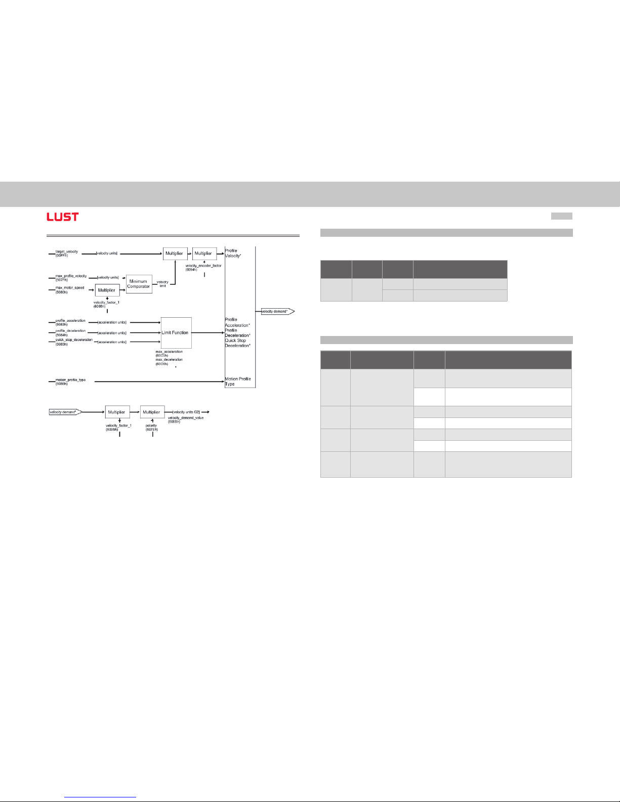
User Manual CANopen/EtherCAT
54
Structure of operation mode
Figure Structure Profile Velocity Mode
9.2.1 Mode-dependent bits in the control word
The structure presented below is based on this operation mode:
Object
No.
Object
Name
Object
Code
Type
8 Stop
0 Execute the motion
1 Stop axle
Table Profile velocity mode bits of the status word
9.2.2 Mode-dependent bits in the status word
Object
No.
Object
Name
Object
Code
Type
10 Target reached
0
Stop = 0: Target velocity not (yet) reached
Stop = 1: Axle decelerates
1
Stop = 0: Target velocity reached
Stop = 1: Axle has velocity 0
12 Speed
0 Speed is not equal to 0
1 Speed is equal to 0
13
Max. Slippage error
0 Maximum slippage not reached
1 Maximum slippage reached
14
Rot 0 1
Axle at standstill
Speed is much lower than parameter
745 MON_REF WINDOW
Table Profile velocity mode bits of the status word
Page 55
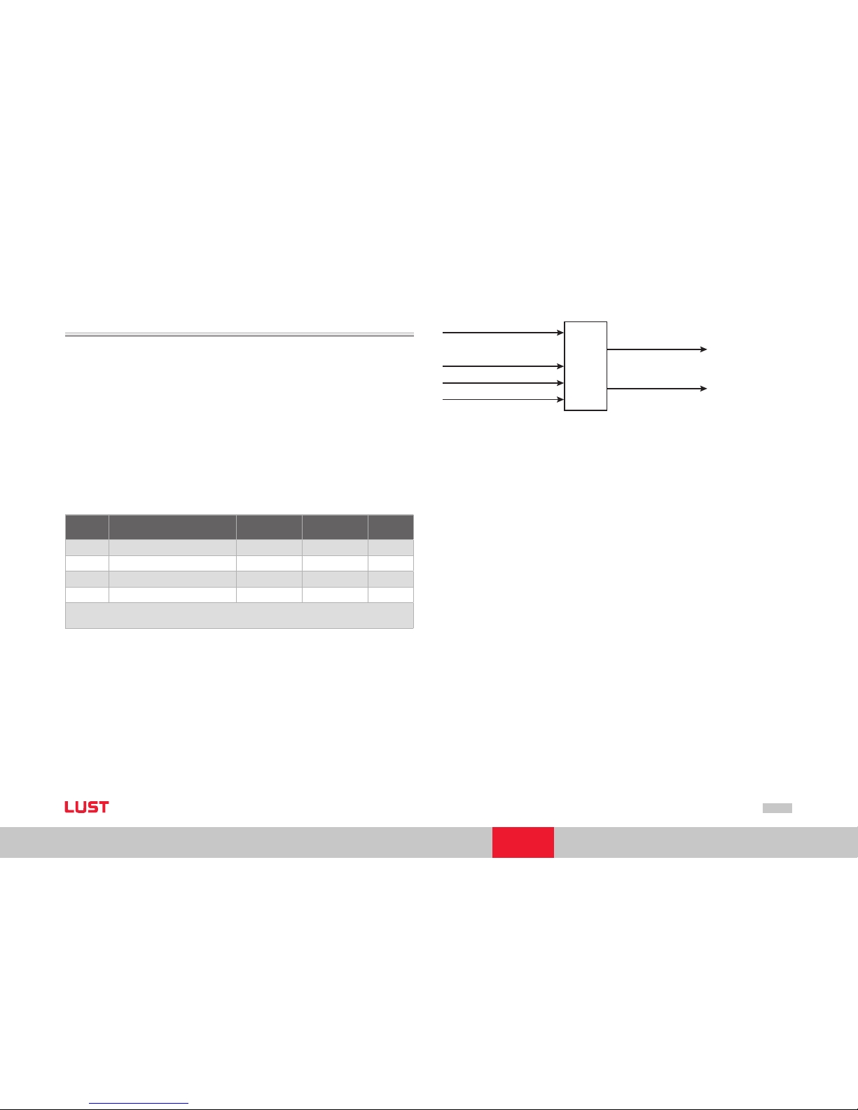
User Manual CANopen/EtherCAT
55
[Chapter 9]
9.3 Homing mode
This mode (Mode of operation = 6) is used to perform a homing of a position- controlled axle. The drive executes a movement according to the programmed reference run
type (homing method).
The various homing methods differ in the integration of hardware limit switch, reference
cam and zero pulse into the encoder system. It should be noted in this that, for limit
switch and reference cam functionality, appropriate digital inputs should be configured:
Limit switch function
LCW - right side HW limit switch
LCCW - left side HW switch
HOMSW - reference cam
The following objects are supported by the device for this operation mode:
Object
No.
Object
Name
Object
Code
Type Attr.
0x607C Home_Offset VAR Integer32 rw
0x6098 Homing _Method VAR Integer8 rw
0x6099 Homing _Speeds * ARRAY Unsigned32 r w
0x609A Homing_ Acceleration VAR Unsigned32 rw
* 0x6099.01 - Quick jog sp eed
0x6099.02 - Slow jog speed
Table Homing mode
Homing
control_word
homing_speeds
homing_acceleration
home_offset
status_word
position_demand_value*
Figure Homing func tion
ServoOne suppor ts all 35 homing methods defined in DS402.
The individual homing methods are described in the device application manuals with
regard to their function and movement sequencing.
Home Off set:
The HOME OFFSET object is the difference bet ween position 0 of the application and the
HOME POSITION found during homing. It is represented in position unit s. At the end of
a homing run the HOME OFFSET is added to the HOME POSITION found. All subsequent
absolute positioning operations relate to this new home position.
A change in the referencing run type and the associated properties is possible in two
ways. The reference run can be changed either via DriveManager or CAN.
For configuration via CANopen the objects of the homing mode can be directly
addressed. For example, for a change to the reference run type, object 0x6098 can be
changed.
Page 56

User Manual CANopen/EtherCAT
56
9.3.1 Mode-specific bits in the control word
Bit 4 - HOMING OPERATION START
Bit 8 - STOP
Bit Name Value Description
4
Homing
operation star t
0 Homing mode inactive
0 ð 1 Star t homing mode
0 Homing mode active
1 ð 0 Inter rupt homing mode
8 Stop
0 Execute the instructions of bi t 4
1 Stop axle with profile deceleration
Table Homing Mode Bits of the control word
9.3.2 Mode-specific bits in the status word
Bit 10 - TARGET REACHED
Bit 12 - HOMING ATTAINED
Bit 13 - HOMING ERROR
Bit 14 - ROT_0
Bit Name Value Description
10 Target reached
0
Stop = 0: Home position not reached
Stop = 1: Axle decelerates
1
Stop = 0: Home position reached
Stop = 1: Axle has velocity 0
12
Homing
attained
0 Homing mode not yet completed
1 Homing mode carried out success fully
13
Homing
error
0 No homing erro r
1
Homing error occurred;
Homing mode not carried out successfully
The error cause is found by reading the error code
14
ROT_0 1
Axle at standstill
Speed is much lower than parameter
745 MON_REF WINDOW
Table Homing Mode bits of the status word
Page 57
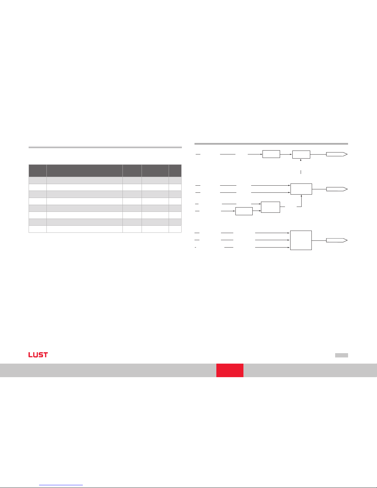
User Manual CANopen/EtherCAT
57
[Chapter 9]
9.4 Profile position mode
In this operation mode (mode of operation =1) the axle executes relative or absolute
single positioning movements.
Object
No.
Object
Name
Object
Code
Type Attr.
0x607A Target_Position VAR Integer32 r w
0x607d Software Position Limit ARRAY Integer32 rw
0x6081 Profile _Velocity VAR Unsigned32 rw
0x6083
Profile_ Acceleration VAR Unsigned32 rw
0x6084
Profile_D eceleration VAR Unsigned32 rw
0x6085 Quick Stop deceleration VAR Unsigned32 rw
0x6064
Position actual value VAR I nteger32 r
0x607E Polarity VAR U Int8 rw
Table Profile Position Mode
Units of the parameters are set by way of the Scaling Wizard or the objects from the
factor group.
Structure of operation mode
Figure Structure Profile Position Mode
target_position
(607Ah)
[position
units]
position_factor
(6093h)
polarity (607Eh)
Limit
Function
Multiplier
position
velocity
acceleration
Limit Function
Limit Function
Multiplier
Minimum
Comparator
positio_range_limit (607Bh)
software_position_limit
(607Dh)
home_offset (607Ch)
velocity
limit
[speed units]
[speed units]
[speed units]
[acceleration units]
[acceleration units]
[acceleration units]
velocity_factor_1
(6095h)
profile_velocity
(6081h)
end_velocity
(6082h)
max_profile_velocity
(607Fh)
max_motor_speed
(6080h)
profile_acceleration
(6083h)
profile_deceleration
(6084h)
quick_stop_deceleration
(6084h)
max_acceleration
(60C5h)
max_deceleration
(60C8h)
Page 58

User Manual CANopen/EtherCAT
58
9.4.1 Mode-specific bits in the control word
Bit 4 - New setpoint
Bit 5 - Change set immediately
Bit 6 - abs/rel
Bit 8 - Stop
Bit Name Value Description
4 New setpoint
0 Does not assume target position
1 Assume t arget position
5
Change set
immediately
0
Finish the current positioning and then star t the next
positioning
1
Interrupt the actual positioning and start the next
positioning
6 abs /rel
0 Target position is an absolute value
1 Target position is a relative value
8 Stop
0 Execute positioning
1
Stop axle with profile de celeration (if not supp orted
with profile acceleratio n)
Table Profile position mode bit s of the control word
9.4.2 Mode-specific bits in the status word
Bit 10 - Target reached
Bit 12 - Set-point acknowledge
Bit 13 - Following error
Bit 14 - ROT_0
Bit Name Value Description
10
Target
reached
0
Stop = 0: Target position not reached
Stop = 1: Axle decelerates
1
Stop = 0: Target position reached
Stop = 1: Velocity of axle is 0
12
Setpoint
acknowledge
0
Trajectory generator has not assumed
the positioning value s (yet)
1
Trajectory generator has assumed the positioning
values
13
Following error
0 No following error
1 Following er ror
14
ROT_0 1
Axle at standstill speed is much lower
than parameter 745 MON_ REFWI NDOW
Table Profile Position Mode bits of the status word
9.4.3 Functional description
In this OPERATION MODE two different options for target position input are supported.
SET OF SETPOINTS:
When the target position is reached, the drive directly approaches the next target
position; the axle is not stopped when the first target position is reached.
Page 59
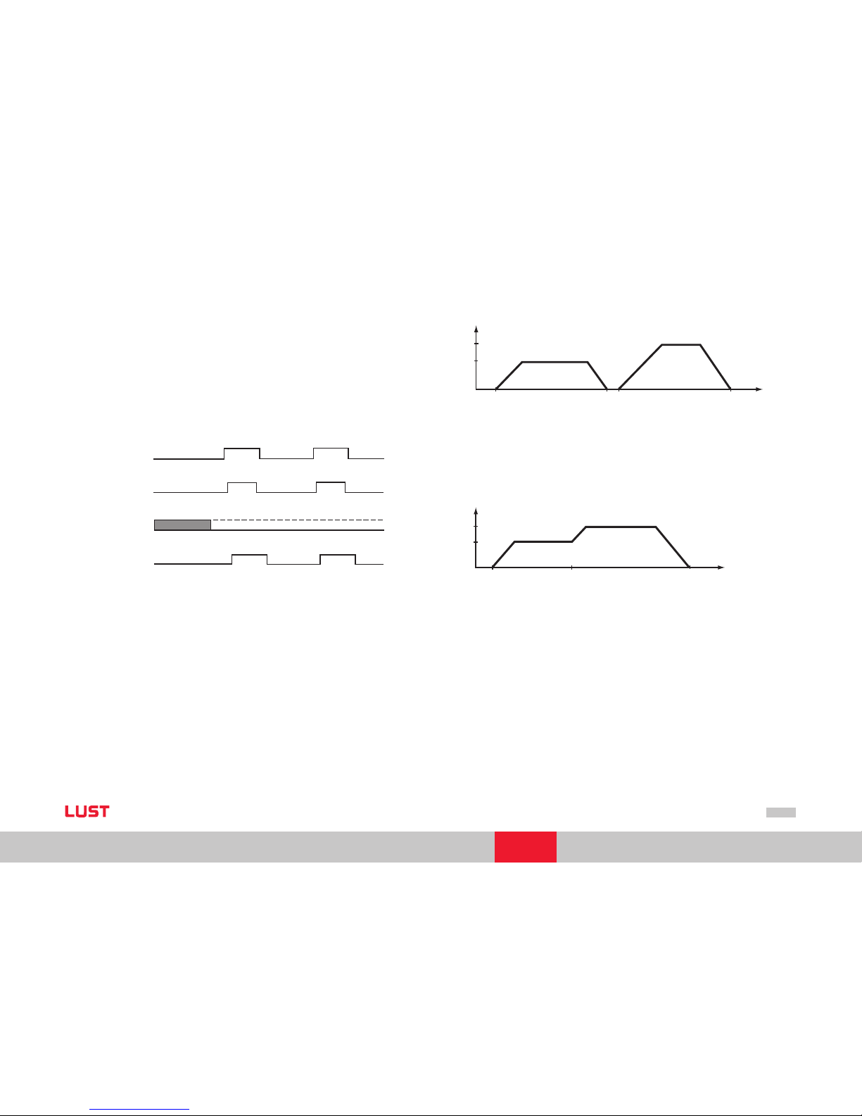
User Manual CANopen/EtherCAT
59
[Chapter 9]
SINGLE SETPOINT:
When the target position is reached the drive indicates the fact to the master. Then the
drive receives a new setpoint. At each target position the drive is stopped before being
moved on to the next target position.
The two options are controlled by way of the timing of the NEW SETPOINT and CHANGE SET IMMEDIATELY bits in the control word and the SETPOINT ACKNOWLEDGE bit in
the status word. These bits allow a new positioning operation to be initiated even while
the current one is ongoing.
data
new_setpoint
change_set_immediately
setpoint_acknowledge
(1)
(2)
(3)
(4)
(5)
(6)
Figure Setpoint transmis sion from a host computer
If the “CHANGE SET IMMEDIATELY“ bit is set to “0“ (solid line in above diagram) a
SINGLE SETPOINT is expected by the drive (1).
When the setpoint has been transmitted to the drive, the master activates the positio ning by setting the ‚New setpoint‘ bit in the control word (2). The drive responds by setting the “Setpoint acknowledge“ bit in the status word (3) once the new data has been
detected and saved. Now the master can delete the “New setpoint“ bit (4). Then the
drive signals by deleting the “set-point acknowledge“ bit that a new setpoint is accepted
(5). In the diagram the mechanism initiates a speed 0 on reaching the target position
at time t1. After the message indicating the target position has been reached, the next
target position can be initiated at time t2.
velocity
v
2
v
1
t
0
t
1
t
2
t
3
time
Figure Single setpoint
If the “CHANGE SET IMMEDIATELY“ bit is set to “1“ (broken line in Figure “Setpoint
transmission“), the new target position is adopted immediately. In the Figure “Change
Set Immediately“ the drive receives the first target position at the time t0. At the time
t1 the drive receives the second target position. The drive immediately implements the
movement to the second target position.
velocity
v
2
v
1
t
0
t
1
t
2
time
Figure Change set immediately
Page 60
User Manual CANopen/EtherCAT
60
Page 61
User Manual CANopen/EtherCAT
61
[Chapter 10]
10 Emergency Objects
byte 0 1 2 3 4 5 6 7
Bit: 0 ... 15 16 ... 23 24 ... 39 40 ... 47 40 ... 47 48 ... 63
Profile Device Profile DS402 Drive controller
Error
Emergency error
code as per
DS402
Error
register
(Object
1001 h)
Error
number
Error
location
Operating hours meter
(in full hours)
Table Emergency teleg ram
The decisive factors for rapid localization are the error code and error location. In by te
3 of the emergency telegram you will find the error code, which provides an initial
categorisation of the cause of the error. The precise cause of the error is specified by the
error location in byte 4. By tes 5, 6 and 7 contain the internal operating hours meter of
the device.
CANopen errors - i.e. incorrect configurations, bus disturbances etc. - are indicated by
error code 0xFF00.
Note: When an error occurs the controller executes a response as per the pa-
rameterised error response. These can be set separately for individual errors.
Note: The state displays of the 7-segment display are explained in the Appli-
cation Manual.
10.1 Error acknowledgement, general
Device errors can be acknowledged by the following mechanisms:
Control word bit 7, edge-controlled
Control input with programmed reset functionality
Hardware enable ENPO to control terminal
Operation via two buttons
Drive Manager user interface
Writing the value 1 to parameter 153 MPRO_DRVCOM_FaultReset by way of the
control unit or bus system
Note: For a detailed list of all error messages together with remedial messa-
ges refer to the Application Manual ServoOne on our product CD.
10.2 Error acknowledgment via bus system
Another possibility is offered by the object 6040 h Control Word:
Draft 402 6040h VAR Control word I nteger16 rw M
An error acknowledgement is executed by a rising edge at bit 7 in the control word.
Resetting of the error is signalled by transmission of the following emergency message:
ID Data bytes Description
Emergency 00 0 0 00 00 00 0 0 00 00
Emergency message acknowledgment
error
Table Error acknowledgeme nt
If the cause of the error is not eliminated, the drive controller returns to the error state
after transmission of another emergency message.
•
•
•
•
•
•
Page 62
User Manual CANopen/EtherCAT
62
Page 63

User Manual CANopen/EtherCAT
63
[Chapter 11]
11 EDS File, Object Directory
Parameter List
11.1 EDS file, object directory
An EDS file is available for the devices to integrate them into the CAN master. The file
is shipped with the firmware. It contains all the CAN objects of the drive controllers.
Note: ServoOne has parameters with default values in the device that may
deviate from the default values in the EDS file. These are power-stage specific
parameters with contents that are dependent on the size. Examples of such
parameters are:
Para 302 – CON_SwitchFreq
Para 307 – CON_VoltageSupply
Para 651 – DV_CAL_VDC
Page 64
User Manual CANopen/EtherCAT
64
Page 65

User Manual CANopen/EtherCAT
65
[Chapter 12]
12 Bibliography
Operation Manual ServoOne LUST Antriebstechnik GmbH
Gewerbestras se 5 - 9
35633 Lahnau
http://w ww.lust-antriebstechnik.de
User Manual ServoOne LUST Antriebste chnik GmbH
Gewerbestras se 5 - 9
35633 Lahnau
http://w ww.lust-antriebstechnik.de
CiA DS-301 (Rev. 4.0): Application Layer and Communication
Profile
http://w ww.can-cia.org/
CiA DSP-402 (Rev. 2.0): Device
Profile Drives and Motion
Control
http://w ww.can-cia.org/
EtherCAT Communication Speci fication Version 1.0 2004
http://w ww.ethercat.org/
EtherCAT Indicator Speci fication
Proposal V0.91 2005
http://w ww.ethercat.org/
IEC61158-2-12 to IEC61158- 6-12
Page 66
User Manual CANopen/EtherCAT
66
Page 67
User Manual CANopen/EtherCAT
67
[Chapter 13]
13 Appendix Glossary
CiA: (“CAN in Automation“). CAN bus user group, generally defines
a protocol for automation.
CAL: (CAN A pplication Layer) CiA protocol, primarily describes the way in
which variables are transmitted without de fining their function or
content.
Subsets:
CMC: (CAN based Message Specificatio n). Sets out the definition
described above. Is accepted by most CAN suppliers. LUST confor ms
to this definition.
NMT: (Network Managem ent). Required for masters in the CAN
system. Not impl emented by LUST because drive controllers are always
slaves and have no “control function“.
LMT: (Layer Management). See N MT
DBT: (Identifier Distributor). See NMT
CANopen: Based on CAL definition
Corresponds to CiA Draft Standard 3 01
Extends the CAL definition to include function and unit assignment
of the predefined variables
This definition is being drafted by CiA and various
user groups (MOTI ON for drive technolo gy and I/O
for inputs/outputs) (e. g. variable for torque in Nm).
General points on the various protocol definitions
CAL: Mainly in us e in Europe, LUST has currently implemented a protocol
which can be acti vated by a CAL master.
The initialisation is simpler than CAL (CCDA), for example addressing
by way of jumper, which has no influence on operation.
DeviceNet: Mainly in the USA (corre sponds to CAL definition).
Page 68
User Manual CANopen/EtherCAT
68
Page 69

User Manual CANopen/EtherCAT
69
[Chapter 14]
Index
Symbols
32-bit variables 29
A
Abort protocol 29
Access to device parameters 30
Activation 41
Acyclic synchronous type 34
Address assignment 9
Address setting via DIP switch 10
Appendix 67
Application of screens 35
Assignment of connection X19 12
Asynchronous types no. FE h and FF h 34
B
Bibliography 65
Bit combinations 43
Bit of the controlword 50
Bootup 27
Bus address parameters 9
Bus module 2
C
Calculation correlations 46
CAL specification 8
CANopen 44
CANopen functionality of ServoOne 7
CANopen interface 11
CANopen option 10
Change modes in diagram 23
Change Set Immediately 59
CiA DS-301 7, 8
CiA DSP-402 8
CoE 38
Commissioning 19
Commissioning and configuration CANopen 19
Commissioning instructions 20
Commissioning sequence 19
Commissioning via DriveManager 21
Communication objects 27
Configuration 19, 25
Configuration for operation in a controller 40
Connecting cable 16
Connection 9
Connectors 11
Control field 29
Control functions 22
Control word 43, 51
Control word bits 50
Control word DS402 50
Cross-manufacturer communication 7
Cyclic synchronous types 34
D
Data handling 21
Data types 29
Description 52
DEVICE CONTROL 50
Device control and state machine 41
DEVICE CONTROL COMMANDS 50
Device control commands 43, 50
DEVICE CONTROL FUNCTION 41
Device controlling 41
Device control objects 45
Device profile DS402 47
Device states 42
Device status table 44
Page 70
User Manual CANopen/EtherCAT
70
Device with EtherCAT Option 17
Digital inputs 47
DIP switches 10
Display of operating states 13, 18
Distributed clocks 39
Documentation, further 8
Download protocol 29
DRIVECOM state machine 43
DriveManager 21, 29
DS402 compatible operation modes 49
E
EDS file 63
Emergency 38
Emergency objects 61
Emergency telegram 61
EoE 38
Error acknowledgement 61
Error acknowledgement, general 61
Error acknowledgement via bus system 61
EtherCAT connection 15
EtherCAT option 15
EtherCAT state machine 39
EtherCAT structure 37
Event control 34
Example of read access 31
Example of use of DIP switches 10
Examples of SDO handling 30
Expedited Multiplexed Domain Protocol 29
F
Factor group 45
Factor group as per DS402 46
Factor group parameters 46
FAULT REACTION ACTIVE 43
Flash sequence 18
Function / assignment 10
Functional description 58
Functionality of operation modes 23
Function of event control 34
G
General information 41
General introduction 7
Glossary 67
H
Hardware enable 14, 18
Heartbeat function 36
Heartbeat protocol 36
Home offset 55
Homing function 55
Homing mode 41, 55
How to use the document 3
How to use this manual 3
I
I/O map, object 60FDH 47
ID No.: 2
Implemented DS301 functionality 27
Implemented DS402 functionality 41
Initial commissioning 21
Input map 48
Installation 11
Introduction 7, 8
M
Mailbox 38
Mapping - general 35
Mapping notes 35
Mapping settings 35
Meanings of LEDs 10, 17
Measures for your safety 7
Page 71

User Manual CANopen/EtherCAT
71
[Chapter 14]
Mode-dependent bits in the control word 54
Mode-dependent bits in the status word 54
Mode-specific bits in the control word 51, 56, 58
Mode-specific bits in the status word 56, 58
Modes of operation 22
Mounting 9
Mounting and connection of EtherCAT 15
Multiplexed Domain Protocol 29
N
NMT 39
NOT READY TO SWITCH ON 42
O
Object 2079h – MPRO_INPUT_STATE 48
Object 208Fh – MRPO_OUTPUT_STATE 48
Object 60FDh – Digit inputs 47
Object directory 63
Object directory of DS301 27
Object index 30
OPERATION ENABLE 42
Operation mode 51, 53
Operation modes DS402 49
Operation mode selection 22
Option codes 44
Overview of supported CAN objects 27
P
Parameter channel 28
Parameter data formats 29
Parameter set download 33
Parameter setting of ServoOne 49
PDO mapping 35
PDO transfer 34
PDO transmission types 34
Pictograms 4
Pin assignment 16
Procedure for commissioning 21
Process data 37
Profile Position Mode 57
Profile position mode 41
Profile Velocity Mode 53
Profile velocity mode 41
Q
QUICK STOP ACTIVE 42
R
READY TO SWITCH ON 42
Reference run types 55
Remedy 33
Representation of data types 29
Restoring factory defaults 21
RJ-45 socket 16
S
Save the settings 21
SDO data transfer 28
SDO Information Service 38
Service data object 28
ServoOne 3
Setting the address 9
Setting the device parameters 27, 37
Setting the software address and Baud rate 20
SINGE SETPOINT 59
Software address 20
Spring-type terminal 12
State control 50
State machine 41, 42
State transitions 39
Status 2
Status bit 44
Status word 51
Status word bits 52
Page 72
User Manual CANopen/EtherCAT
72
Status word DS402 51
STOP function 44
Structure of operation mode 54, 57
Structure Profile Position Mode 57
Supported EtherCAT functionality 37
SWITCHED ON 42
SWITCH ON DISABLED 42
System connection 12
System requirements 8
T
Terminals 9
Test higher-order controller 20
Translation of transmitted values (ASCII) 32
Transmission of TxPDO 34
Transmission speeds 13
U
Units and scalings 45
Upload protocol 29
Users 3
X
XML file 39
Page 73

Page 74

Lust Antriebstechnik GmbH
Gewerbestraße 5-9 • 35633 Lahnau
Germany
Tel. +49 (0) 64 41/9 66-0
Fax +49 (0) 64 41/9 66-137
Internet: www.lust-tec.de
e-mail: [email protected]
Lust Antriebstechnik GmbH
Heinrich-Hertz-Str. 18 • 59423 Unna
Germany
Tel. +49 (0) 23 03/77 9-0
Fax +49 (0) 23 03/77 9-3 97
Internet: www.lust-tec.de
e-mail: [email protected]
ID No.: 110 0.28B.0-00 • 11/2007
 Loading...