

Page 1
EN
EN
FR
ES
C
CDA3000
Engineering
Guide
Inverter drive system
to 90 kW
The easy route
With drive engineering
formula bank
to your drive solution
Page 2
Overview of documentation
Before purchase
With shipment
(depending on supply
pakkage)
CDA3000 Catalogue
Selecting and ordering a
drive system
CDA3000 Operation
Manual
D
Quick and easy initial
commissioning
CANLust Communication
Module Manual
Engineering Guide
CDA3000
C
Dimensioning a drive
system
User Manual
RIVEMANAGER and KEYPAD
D
E
Operation via
RIVEMANAGER and KEYPAD
D
CANopen Communica-
tion Module Manual
Application Manual
Traction and lifting
drives, Rotational drives
F1
Adaptation of the drive
system to the application
PROFIBUS-DP Communi-
cation Module Manual
C
G1
Project planning, installa-
tion and commissioning of
the CDA3000 on the field
bus
Project planning, installa-
tion and commissioning of
the CDA3000 on the field
G2
Project planning, installa-
tion and commissioning of
the CDA3000 on the field
bus
Engineering Guide CDA3000
ID no.: 0840.25B.1-00 Sheets for Engineering Guide
Date: December 1999
We reserve the right to make technical changes.
G3
bus
Page 3
About this manual
This guide is intended for users looking for background information
relating to the engineering of inverter drives.
The term “engineer ing” (or “project planning”) in this context covers the
design and configuration of c omplex technical sy stem s thr ough to rec eipt
of the order to implement. General project planning tasks including:
➢ Analysis of the task
➢ Concept design of the system
➢ Design of the system c om ponents
➢ Selection of the best solution to be implem ented.
How to use this
manual
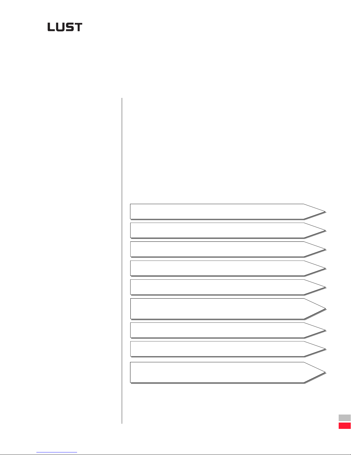
Project planning process
System overview, Revision history
1 Analysis of task
2 Definition of drive
3 Selection of inverter module
4 Selection of user and communication
modules
5 Selection of supplementary components
6 Tips for system installation
1
2
3
4
5
6
Engineering Guide CDA3000
Appendix:
Formula bank, Copy templates
Bibliography and index
Table of contents
A
DE
EN
FR
Page 4
Project planning
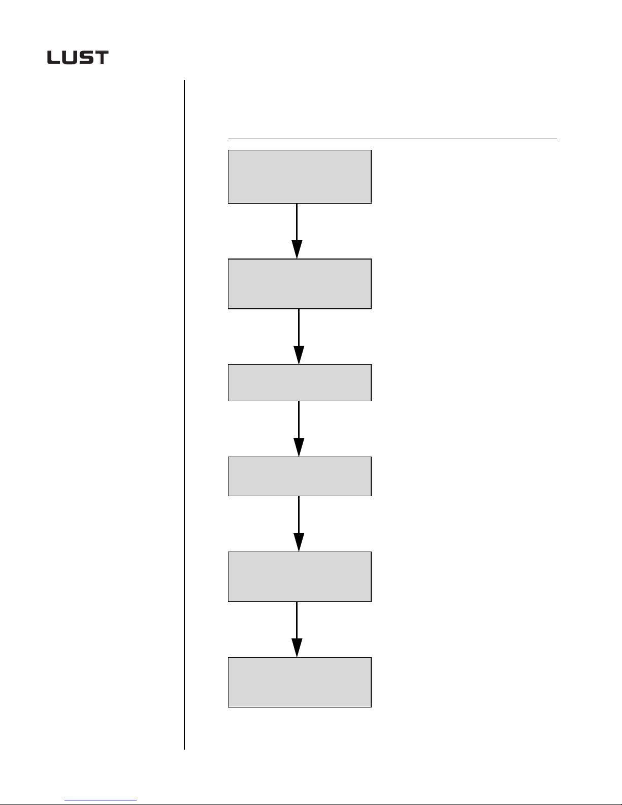
flowchart
STEPS SECTION
➢ Basics - see section 1
1.
2.
3.
Record movement task in
processing process
Calculate drive variables,
such as power output, torque,
speed, etc.
Select motor, transmission gear
and gearing
➢ Checklist for recording
the task - see section 2.1
➢ See sections 2.2 to 2.4
➢ See sections 2.5 to 2.6
4.
5.
6.
Select inverter module and
software performance
Select user
and/or communication
modules
Select supplementary
components such as filters,
line choke, etc.
➢ See section 3
➢ See section 6
➢ See section 4
➢ See section 5
Engineering Guide CDA3000
Page 5
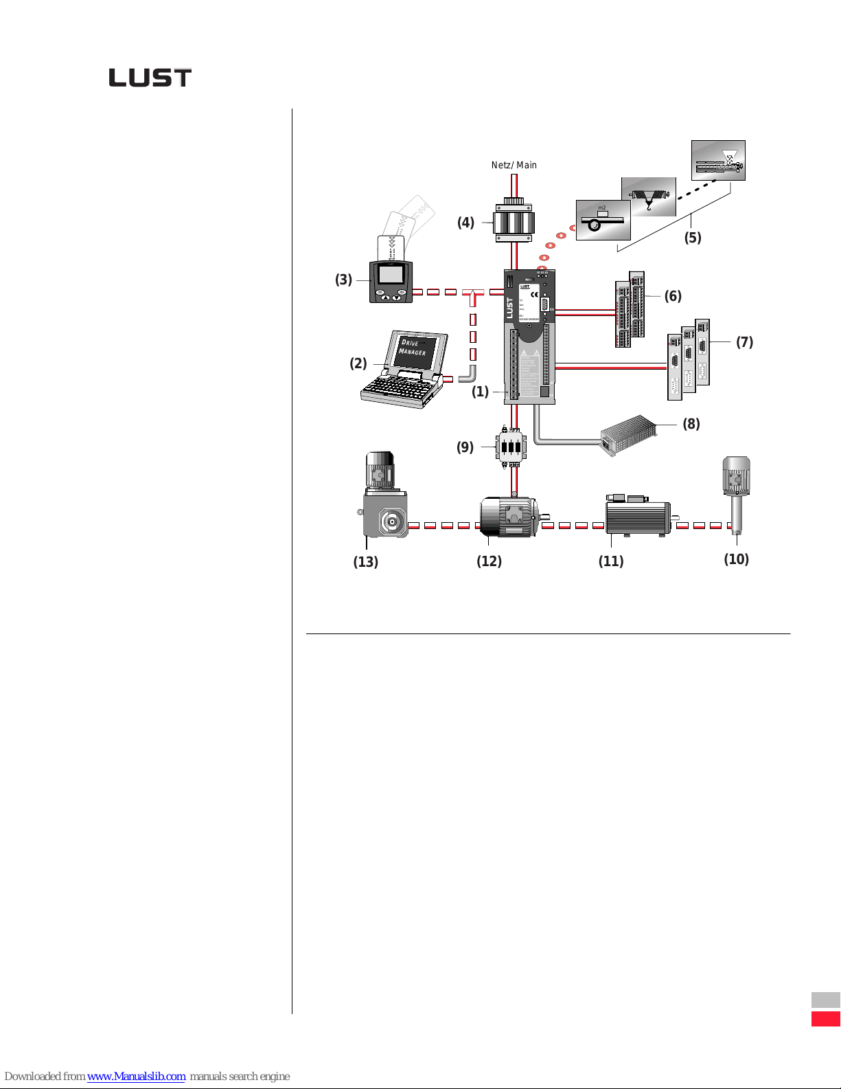
Drive system layout
Netz/ Main
(3)
(2)
(13)
T
R
A
D
M
R
S
A
C
T
R
A
RD
M
A
S
C
SMART
CARD
stop
start
return
enter
D
R
IV
E
M
A
N
A
G
(4)
H1 H2 H3
ANTRIEBSTECHNIK
D-35633 Lahnau
Typ:
Netz:
Ausg.:
X4
SN.:
000.000.00000000
E
R
(1)
!
ACHTUNG
Kondensatorentladezeit >3 Min.
Betriebsanleitung
beachten!
WARNING
capacitor disscharge
time >3 minutes.
Pay attention to the
operation manual!
X2
ATTENTION
temps de decharge
du condensteur
>3 min. observer le
mode dèmploi!
X1
X3
m2
(5)
12
34
12
5
6789
34
(6)
5
678
10 11
12
910
16 17
11 12
18 19
16 17 18
20
19 20
1
2
12
12
(7)
(8)
(9)
(12)
(11)
(10)
Engineering Guide CDA3000
System modules Section
(1) Inverter module See section 3
RIVEMANAGER PC user software See section 4.1.4
(2) D
EYPAD control unit See section 4.1.3
(3) K
(4) Line choke See section 6.1
(5) Software performance - Preset solutions See section 4.2
(6) I/O terminal expansion See section 4
(7) CAN
Lust
, CAN
open
,
Profibus-DP bus interface See section 5.3
(8) Braking resistor See section 6.3
(9) M oto r c ho kes See section 6.2
(10) HF spindle See section 2.5.5
(11) Asynchronous servomotor See section 2.5.2
(12) IEC standard motor See section 2.5.1
(13) Geared motor See section 2.5
DE
EN
FR
Page 6

1 Analysis of task
1.1 Systematic thinking ................................................ 1-2
1.1.1 Inverter system .................................................... 1-2
1.1.2 System environment ............................................1-3
1.2 Process analysis ..................................................... 1-4
1.2.1 Example of a process analysis in comparison
with functional analysis ....................................... 1-4
1.3 Characteristic values of machinery ....................... 1-9
1.3.1 Movement requirement .......................................1-9
1.3.2 Moment of inertia .............................................. 1-12
1.3.3 Manipulating range and accuracy ...................... 1-13
1.3.4 Load torque ....................................................... 1-19
2 Drive definition
2.1 Recording of movement task ................................. 2-2
2.2 Drive definition via normogram ............................. 2-6
2.2.1 Example of solution with four-pole motor ............ 2-7
2.2.2 Example of solution with six-pole motor .............2-8
2.3 Drive definition via power rating ............................2-9
2.3.1 Example 1: Traction drive .................................. 2-10
2.3.2 Example 2: Lifting drive ..................................... 2-12
2.4 Drive definition via L
UDRIVE PC PROGRAM ...............2-13
2.4.1 Example 1: Trolley drive for gantry crane ...........2-15
2.4.2 Example 2: Belt turning station for truck engine
distribution ........................................................ 2-20
2.5 Selection of motor ................................................ 2-24
2.5.1 Characteristic values of standard three-phase
AC motors ......................................................... 2-26
2.5.2 Characteristic values of asynchronous
servomotors ASx ............................................... 2-35
2.5.3 Characteristic values of reluctance motors ........ 2-41
2.5.4 Characteristic values of synchronous motors .....2-44
2.5.5 Characteristic values of high-frequency motors . 2-47
Engineering Guide CDA3000
Page 7
2.6 Selection of gearing ..............................................2-48
2.6.1 Transmission gear .............................................2-48
2.6.2 Characteristic values of standard gears ..............2-49
2.6.3 Characteristic values of planetary gears .............2-49
3 Selection of inverter module
3.1 Technical data .........................................................3-3
3.1.1 Acceptance tests .................................................3-5
3.1.2 Ambient conditions ..............................................3-6
3.1.3 Installation and cooling methods ..........................3-7
3.2 Extreme operating conditions ..............................3-14
3.2.1 Mains side/system condition ..............................3-16
3.2.2 Loading on the supply system ............................3-20
3.2.3 General points on the mains connection .............3-21
3.2.4 Operation of fault current breakers .....................3-23
3.2.5 Switching at the inverter input ...........................3-24
3.2.6 High-voltage test/Insulation test .........................3-24
3.2.7 Forming of the DC-link capacitors ......................3-25
3.2.8 Direction of rotation and terminal designation ....3-27
3.2.9 Switching at the inverter output .........................3-28
3.2.10 Short-circuit and ground fault proofing ...............3-29
3.2.11 Motor cable length .............................................3-29
3.2.12 Voltage load on the motor winding .....................3-31
3.2.13 Motor protection possibilities .............................3-31
3.2.14 Power reduction .................................................3-33
3.2.15 Calculation of effective inverter capacity
utilization ...........................................................3-55
3.2.16 Measurement on the inverter module .................3-58
Engineering Guide CDA3000
3.3 Special applications ..............................................3-60
3.3.1 Project planning for three-phase AC motors .......3-60
3.3.2 Efficiency of the motor control methods .............3-62
3.3.3 Standard inverter operation ................................3-67
3.3.4 70 Hz characteristic with 25% field weakening ..3-69
3.3.5 87 Hz characteristic / Expanded manipulating
range .................................................................3-73
3.3.6 Multi-motor operation on one inverter ................3-76
3.3.7 DC network operation ........................................3-79
3.3.8 Design of the braking resistor ............................3-83
3.3.9 Power failure bridging ........................................3-87
DE
EN
FR
Page 8

4 Software functions
4.1 User interface and data structure .......................... 4-2
4.1.1 Data structure ..................................................... 4-2
4.1.2 Initial commissioning ........................................... 4-6
4.1.3 Operation via K
4.1.4 Operation via D
EYPAD KP200 .............................. 4-11
RIVEMANAGER ..............................4-12
4.2 Device and terminal view ..................................... 4-15
4.2.1 Specification of control terminals ....................... 4-16
4.2.2 Isolation method and connection tips ................. 4-19
4.3 Preset solutions .................................................... 4-20
4.3.1 Traction and lifting drive .................................... 4-24
4.3.2 Rotational drive ................................................. 4-39
4.3.3 Field bus operation ............................................ 4-49
4.3.4 Master/Slave operation ...................................... 4-56
5 Communication and user modules
5.1 Principle of function ............................................... 5-2
5.2 User module ............................................................5-3
5.3 CAN-BUS ................................................................. 5-4
5.3.1 Interconnection of inverter modules on the
CAN bus .............................................................. 5-6
5.3.2 Communication via CAN
5.3.3 Communication via CAN
.................................5-8
LUST
.............................. 5-12
open
5.4 PROFIBUS-DP ........................................................ 5-13
5.4.1 Interconnection of LUST drive units with the
PROFIBUS-DP Gateway ...................................... 5-14
5.4.2 Interconnection via the PROFIBUS-DP module ....5-17
5.4.3 Communication via PROFIBUS-DP ..................... 5-18
Engineering Guide CDA3000
Page 9
6 Selection of supplementary components
6.1 Line choke ...............................................................6-2
6.1.1 Effect of the line choke ........................................6-2
6.1.2 Operation with reactive current compensation
system .................................................................6-4
6.1.3 Technical data of line chokes LR3x.xxx ................6-6
6.1.4 Assignment of line choke to inverter module ........6-7
6.2 Motor choke ............................................................6-8
6.2.1 Technical data of the motor chokes .....................6-8
6.2.2 Assignment to the inverter modules ...................6-10
6.3 Braking resistors ...................................................6-12
6.3.1 Technical data of series BRxxx, xx-xx ................6-12
6.3.2 Assignment to inverter modules CDA3000 .........6-13
6.4 Radio interference suppression filter ...................6-14
6.4.1 Technical data of RFI filters EMC34.xxx ..............6-14
6.4.2 Permissible motor cable length with internal
RFI filter .............................................................6-15
6.4.3 Permissible motor cable length with internal
and external RFI filter .........................................6-16
6.4.4 Permissible motor cable length with external
RFI filter .............................................................6-16
Engineering Guide CDA3000
7 System installation
7.1 Heat discharge from the switch cabinet ................7-2
7.1.1 Basic terms for calculation ...................................7-2
7.1.2 Effective switch cabinet surface ...........................7-3
7.1.3 Calculation of filter fans .......................................7-4
7.1.4 Calculation of heat exchangers ............................7-5
7.2 Heat transfer by heat conductance ........................7-7
A Formula bank
A.1 Mathematical symbols ........................................... A-2
A.1.1 SI units ................................................................A-2
DE
EN
FR
Page 10

A.1.2 Important units ....................................................A-4
A.2 Drive engineering equations ..................................A-5
A.2.1 Basic physical equations .....................................A-5
A.2.2 Power ..................................................................A-6
A.2.3 Torques .............................................................A-11
A.2.4 Work .................................................................A-12
A.2.5 Friction .............................................................. A-14
A.2.6 Effective motor torque/power output ..................A-15
A.2.7 Choice of max. acceleration ...............................A-17
A.2.8 Mass moments of inertia ...................................A-20
A.2.9 V/t diagram ........................................................ A-27
A.2.10 Efficiencies, coefficients of friction and density ..A-30
A.2.11 Motor lists ......................................................... A-34
A.3 Protection ..............................................................A-40
A.3.1 Protection to IEC/EN ...........................................A-40
A.3.2 Protection to EEMAC and Nema ......................... A-43
B Practical working aids for the project
engineer
C Bibliography and source reference
D Index
Engineering Guide CDA3000
Page 11
1 Analysis of task
1.1 Systematic thinking ................................................1-2
1
2
3
Take your time, especially at
the beginning
1.1.1 Inverter system ....................................................1-2
1.1.2 System environment ............................................1-3
1.2 Process analysis .....................................................1-4
1.2.1 Example of a process analysis in comparison with
functional analysis ...............................................1-4
1.3 Characteristic values of machinery .......................1-9
1.3.1 Movement requirement ........................................1-9
1.3.2 Moment of inertia ..............................................1-12
1.3.3 Manipulating range and accuracy ......................1-13
1.3.4 Load torque .......................................................1-19
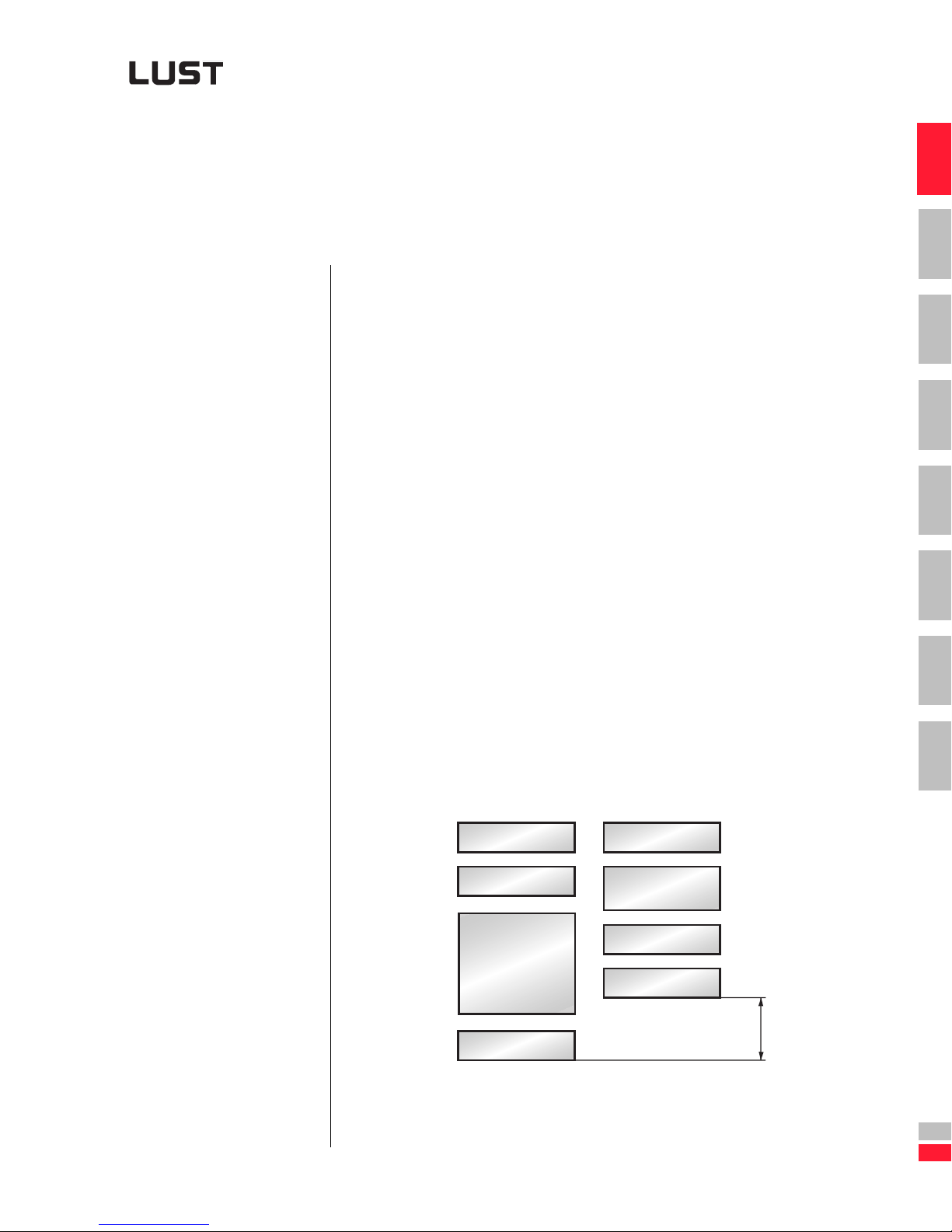
Please note: The more complex the task, the more important is the analy-
sis. A “better” analysis can identif y im pending failures in good time.
"Good" "Better"
Complexity
Complexity
4
5
6
7
A
Engineering Guide CDA3000
Analysis
Intuition/experience
Decision
Analysis
Intuition/experience
Decision
Time and
cost saving
1-1
DE
EN
FR
Page 12
1 Analysis of task
1.1 Systematic
thinking
Thinking differently
[leads to]
Belief
[in turn resulting in]
Acting differently
1.1.1 Inverter system
The chain is only as strong as
its weakest link
efore beginning your project planning you should read thro ugh this
section - it will help you identify how to attain the new solutions you
B
need.
What can we learn from system analysis? The term "system" in this
context means:
➢ a unified whole, distinct from its surr oundings
➢ comprising individual elements
➢ between which fixed relations hips exist
➢ and which perform specific fun ct i ons.
The star ting point for any system analysis is to record, unde rstand and
order the existing inter-relationships within a system. To this end, the system is split down into its subsidiar y areas (compone nts) such that all the
individual components are distinct from each other and the relations
between them become visible.
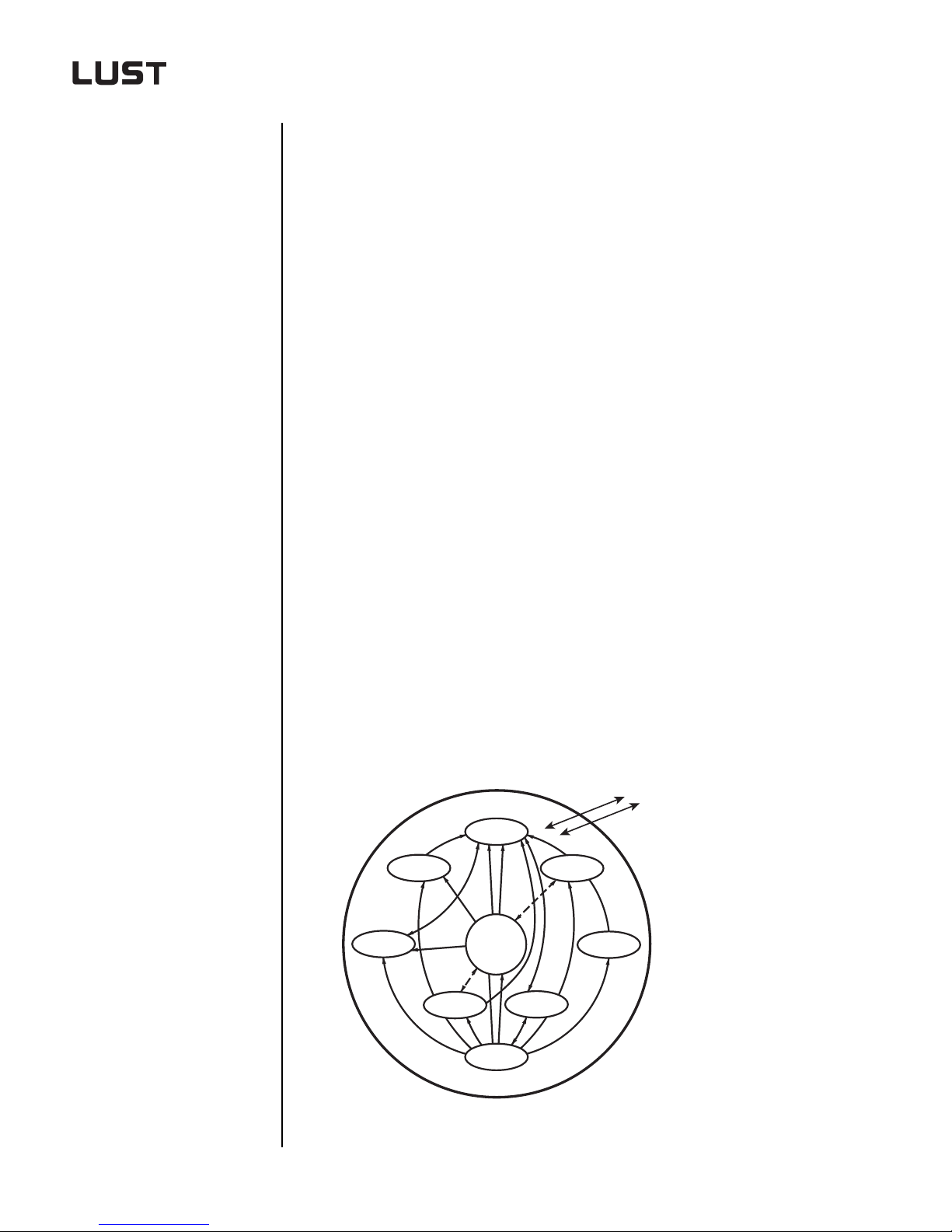
An inverter system comprises the following individual components and
modules:
• Inverter module • Motor choke
• Operator module • Braking resistor
• User module • Cable
• Communication module • Motors
• Software modules •Gearing
• Line choke •etc.
• Mains filter
Interface
to the
System
environment
Inverter
module
Figure 1.1 Inverter system
Engineering Guide CDA3000
Comm.
module
User
module
Braking
resistor
Software
modules
Services
Motor
Gearing
Line choke
1-2
Page 13
1 Analysis of task
In summary: An inverter system is a combination of standalone
products and services which create new usable drive
system properties with added value.
1
1.1.2 System
environment
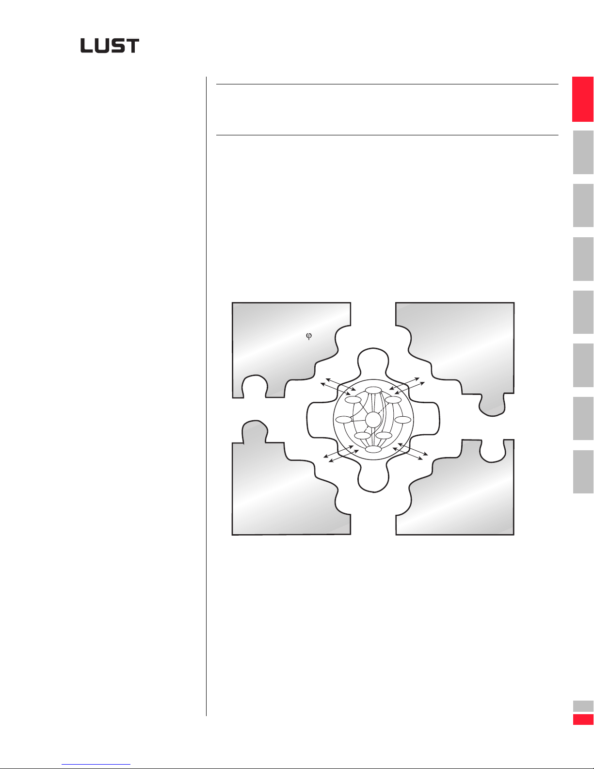
Analysis of the system environment of inver ter drives reveals four interfaces which outline that environment:
1. Interface to the processing pro ces s
2. Interface to the automation process
3. Interface to the surrounding environment and in stallation conditions
4. Interface to the requirements arising from standards, regulations and
safety concerns
Processing process
= f (n, s, )
M
L
Environmental
and installation
conditions
Inverter
module
Comm.
module
module
User
Braking
resistor
Software
modules
Services
Motor
Gearing
Line choke
2
3
4
5
6
7
Engineering Guide CDA3000
Automation
process
Standards,
regulations
and safety
Figure 1.2 System environment
This section deals with the interface to the “processing process”. The
other interfaces are dealt with in the subseq uent sections of the guide.
1-3
A
DE
EN
Page 14
1 Analysis of task
1.2 Process analysis irst find out what processing process
for. Apply the pr inciples o f proces s analysis, bec ause proc ess analy-
sis will provide you with a non-solution-specific view of the tas k at hand.
Do not perform a functional analysis at the beginning of an analysis,
because the functions u sed always describe the specific solution.
The functional analysis is der ived from the value analysis. Its main role is
to eliminate dual functions and to cut the cost per function.
1.2.1 Example of a
process analysis
in comparison
with functional
analysis
Standard screw-type extruder
➢ An extruder is a machine which takes in solid to liquid (synthetic)
molding compounds and presses them out of an opening, for the
most part continuous ly.
It compresses, mixes, plasticizes and homogenizes the compound in
the process.
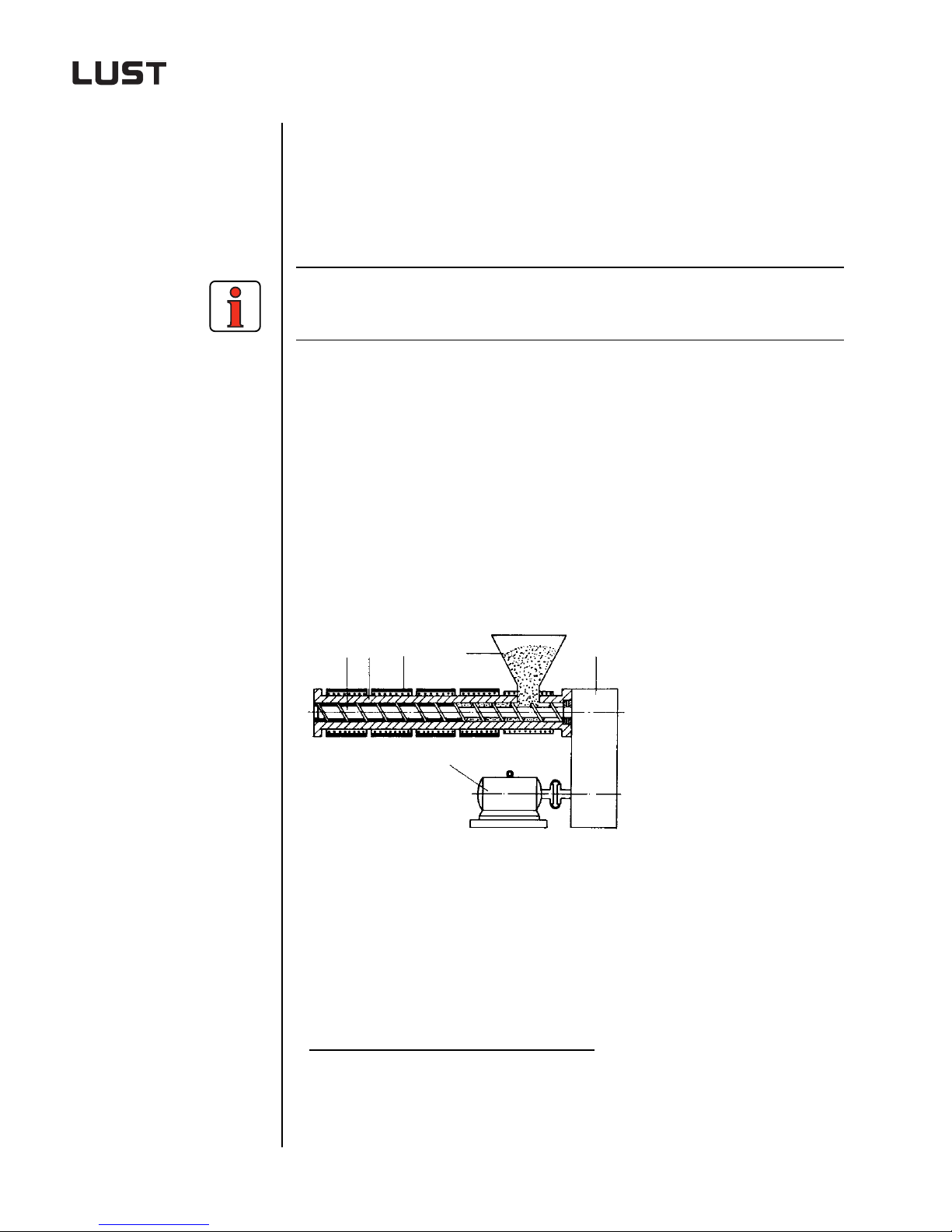
The screw-type extruder shown (see Fig ure 1.3) principally comp rises a
drive unit and a plasticizer unit. The plas ticizer unit consists of a screw
cylinder, a screw, a material funnel, and heating and cooling zones.
1
the drive solution is to be used
2
(2)
(3)
(6)
(4)
(5)
(4) Funnel
(5) Gearing
(6) Motor
(1)
(1) Screw
(2) Cylinder
(3) Heater
Figure 1.3 Schematic of an extr ud er
1. Processing process: Process in the course of which energy, information and/or material is transformed
and conveyed
2. The value analysis method was developed in 1948 by the Purchasing department of General Electric.
Literature: DIN 69910 and VDI 2801.
Engineering Guide CDA3000
1-4
Page 15
1 Analysis of task
The drive unit is formed by a regulated DC drive, gearing and the sc rew
return thr ust bearing, which abs orbs the forces occurring during convey-
ing and plasticizing.
1
M
P
L
ML,
P
n
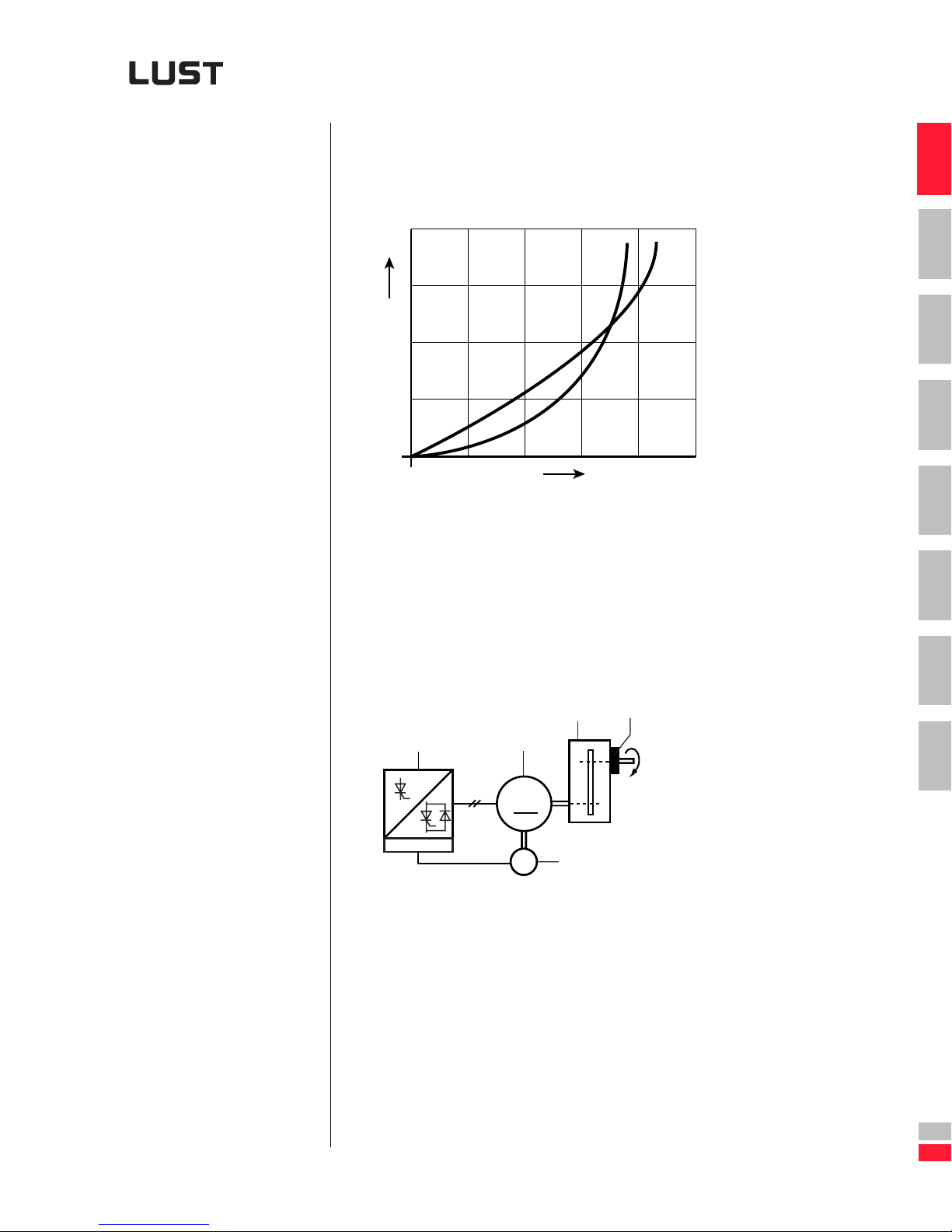
Figure 1.4 Load characteristic of the plastics extruder
Task for a new drive unit
In order to provider a higher degree of machin e availability, the drive is to
be switched from DC to three-phase AC . The DC drive used to date has a
speed manipulating range of 1:1000 and an overload capacity to 200%.
ML = f (n)
P = f (n)
2
3
4
5
6
Engineering Guide CDA3000
(4)
(1)
(2)
M
M
(3)
T
1~
(1) DC controller
(2) DC motor
(3) Tacho
(4) Gearing
(5) Screw return thrust bearing
Figure 1.5 Old solution with DC drive
7
(5)
A
DE
EN
1-5
Page 16
1 Analysis of task
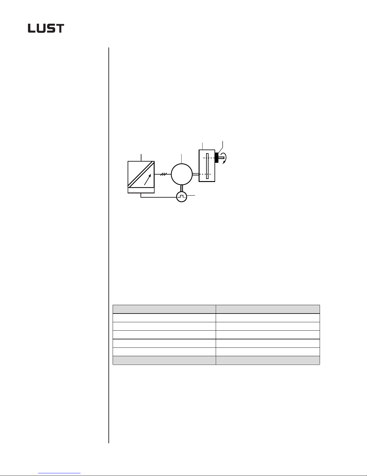
Functional analysis
In a functional analysis each component which per forms a func tion must
merely be replaced by another one. In this case t his means:
• the DC motor is replaced by an AC motor
• the tacho is replaced by a digital encoder and
• the DC controller is replaced by an inverter with field-oriented regulation.
(4)
(1)
~
~
(1) Inverter with field-oriented regulation
(2) AC motor
(3) Encoder
(4) Gearing
(5) Screw return thrust bearing
Figure 1.6 Solution from functional analysis
The functional analysis produces a solution with speed feedback - See
Table 1.1.
DC drive Three-phase AC drive
1 DC controller 1 Inverter with field-oriented regulation
2 DC motor 2 AC motor
3 Tacho 3 Encoder
4 Gearing 4 Gearing
5 Screw return thrust bearing 5 Screw return thrust bearing
Old solution Functional analysis (NEW 1)
(2)
M
3~
M
1
~
(3)
(5)
Table 1.1 Comparison between old solution and solution from functional
Engineering Guide CDA3000
analysis
1-6
Page 17
Process analysis
1 Analysis of task
A process analysis establishes what demands the processing process
places on the drive.
Questions to be answered:
1. What is the movement requirement for processing?
2. Moment of inertia of the processing ma chine, referred to the motor
shaft?
3. What manipulating range is required for the processing process?
4. What load torque needs to be overcome?
Answer the questions in this example:
1. Continuous material flow.
2. Is of no significance in applicat i ons with continuous material fl ow.
3. Speed manipulating range of 1:10.
4. No overload necessary, because the screw of the extruder would
otherwise be damaged. When the screw has become clogged, it is
drawn forward out of the extruder for cleaning.
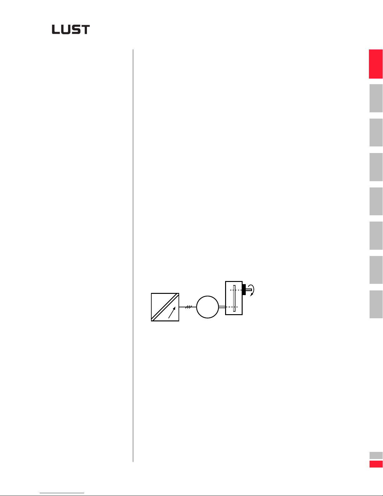
The answers supplied in the process analysis deliver a solution with a
standard inverter wi thout speed feedback. This means a subs tantial co st
reduction.
1
2
3
4
5
6
Engineering Guide CDA3000
~
~
Figure 1.7 Solution f ro m pr oce ss analysis
M
3~
1-7
7
A
DE
EN
Page 18

1 Analysis of task
Comparison of solutions:“Functional analysis / Process analysis”
Solution from functional analysis Solution from process analysis
~
~
M
3~
M
1
~
~
~
M
3~
M
1
~
$
$
NEW 1
Inverter with field-oriented regulation
Figure 1.8 Comparison of solutions
NEW 2
Inverter with VFC
In summary: Always analyze the processing process! Because just
because something is
mean it is
recognized
known
!
does not necessarily
Engineering Guide CDA3000
1-8
Page 19
1 Analysis of task
1.3 Characteristic
values of
machinery
1.3.1 Movement
requirement
ou do not usually need to take account of the detailed s tructure of the
machinery for drive project planning. It can be adequately describe d
by:
1. the movement requirement for processing
2. the moment of inertia of the processing machine, referred to the
motor shaft
3. the manipulating range and ac curacy of the torque, speed and position
4. the character is tic over time of the load torque
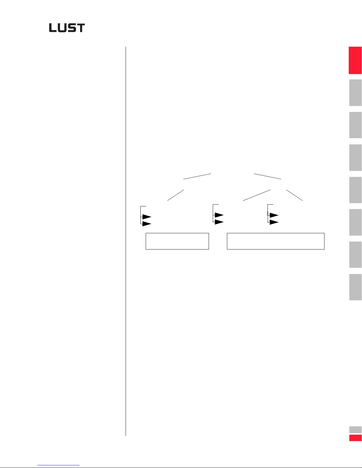
The movement requirement for processing is ro ughly divided into three
groups.
Movement requirements
for processing
Continuous Discontinuous
Continuous material flow
Paper machinery
Textile machinery
Batch processes
Stirrers
Mills
Unit processes
Packaging machinery
Optical machinery
1
2
3
4
5
6
Continuous material flow
Material flow not continuous or irregular
7
A
Engineering Guide CDA3000
DE
EN
1-9
Page 20
1 Analysis of task
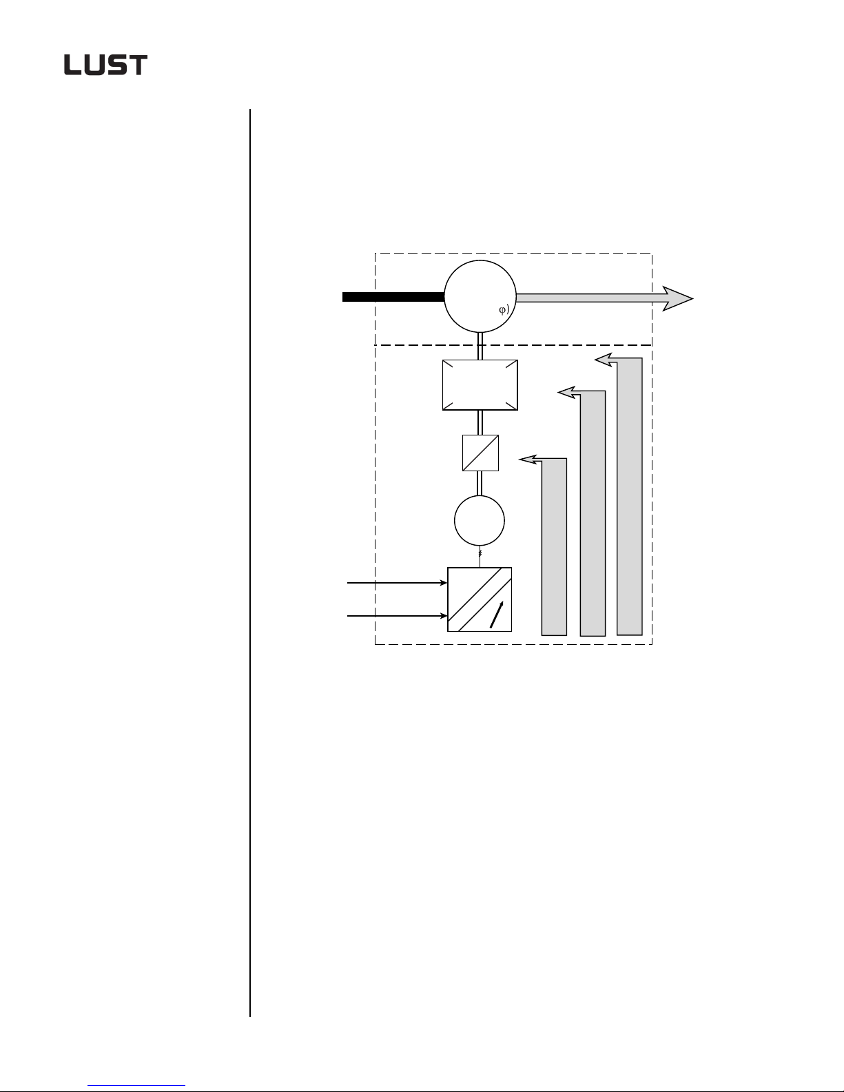
Traction and mechanical function
The movement solution in the processing p rocess in mos t cases involves
a traction function and a mechanical function. The mechanical function
usually generates a non-linear movement. The proce ssing pro cess c ounteracts this movement with a specific load torque.
Processing
material
Energy
Reference
Processing
process
ML=f(n,s,j)
Mechanical
function
X(n2(t))
n
2
n
2
n
1
n
1
M
3~
~
=
~
Product
X
Drive function with
frequency inverter
Drive function with servocontroller
Movement solution
Engineering Guide CDA3000
Figure 1.9 Movement solution in the processing process
1-10
Page 21
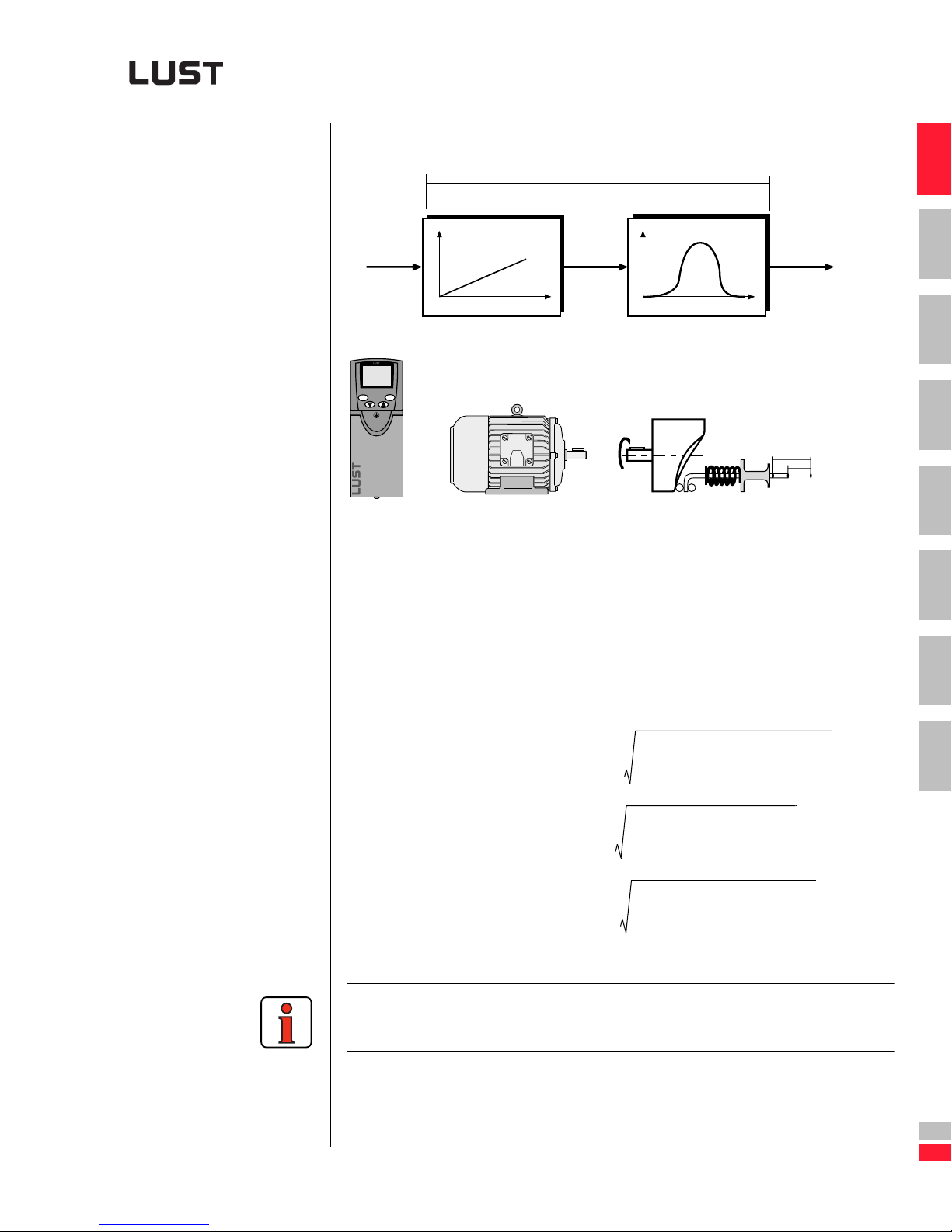
1 Analysis of task
Example of a movement solution
Movement solution
x
t
Drive function x(t) Mechanical function y(x)
stop
start
return
enter
x y(x(t))
t
y
x
ϕ
S
0
S
Figure 1.10 Movement solution split into traction and mechanical function
v/t diagram
The processing cycle of a m achine or plant is typically descr ibed by the
velocity/time profile, also ter med the v/t diagram. From that diagram the
acceleration/deceleration time and the star tup and shutdown frequency
can be determined. This repetition rate of the startup and shutdown
process determines the
1
2
3
4
5
6
7
Engineering Guide CDA3000
➢ motor rating
➢ current load of the
inverter module
➢ and the braking
chopper design
M
I
P
eff
eff
eff
M
-----------------------------------------------------------------=
1
2
t1M
2
2
t2M
2
t
⋅+⋅+⋅
n
n
T
2
I
1
--------------------------------------------------------=
t1I
2
2
t2I
2
t
⋅+⋅+⋅
n
n
T
2
P
t1P
1
-------------------------------------------------------------=
2
2
t2P
2
t
⋅+⋅+⋅
n
n
T
For more information on the subject of the v/t diagram refer to the formula
bank in See Appendix A.2.9.
1-11
A
DE
EN
Page 22
1 Analysis of task
1.3.2 Moment of
inertia
The moment of inertia of a machine or a machining process is kept as low
as possible. However, the room for maneuver in terms of dimensioning is
very low as a result of the pressure for technological optimization.
The moment of iner tia of motors is of great significa nce for the overall
drive design in cases of fre quent and rapid change s of speed, wh ile in
rotational drives, such as a sugar centrifuge or a continuous winding
drive, a reduction in the moment of iner tia of the motor has little or no
effect on the overall drive design.
For more information on this subject refer to the formula bank in section
A.2.8 and section 2.
Engineering Guide CDA3000
1-12
Page 23
1 Analysis of task
1.3.3 Manipulating
range and
accuracy
Definition of terms
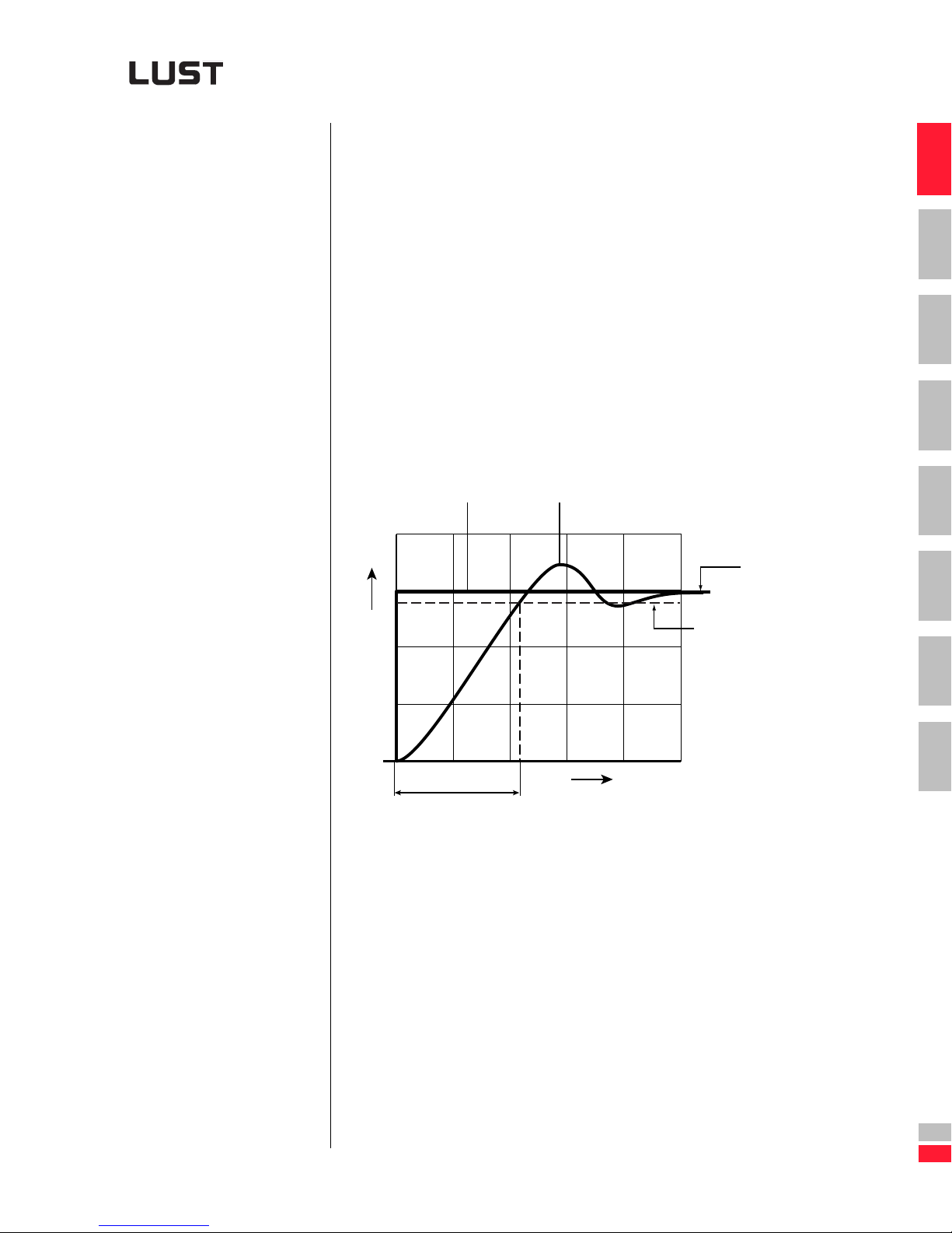
The desired torque rise time, the speed m anipulat ing range and the pos itioning accuracy are likewise deter m ined by the techno logical pro cessin g
process.
In the following some terms are defined mo re closely, in order to avoid
misunderstandings be tween you - the customer - and th e drive manufacturer.
Torque rise time
The torque rise time is the time which elapses after a reference step from
0 to MN until the actual value of the torque in the motor has reached 95%
of the nomi nal value.
The torque rise time is depend ent on the con tr ol methods ap plied and on
the electrical pa rameters of the motor us ed. As the speed increases the
voltage reserve for injection of a current falls, causing the torque rise time
to increase.
(1)
(2)
100%
1
2
3
4
5
M(t)
T
A
TA= Torque rise time
(1) Reference
(2) Actual
Figure 1.11 Torque rise time
6
95 %
7
t
A
Engineering Guide CDA3000
DE
EN
1-13
Page 24
1 Analysis of task
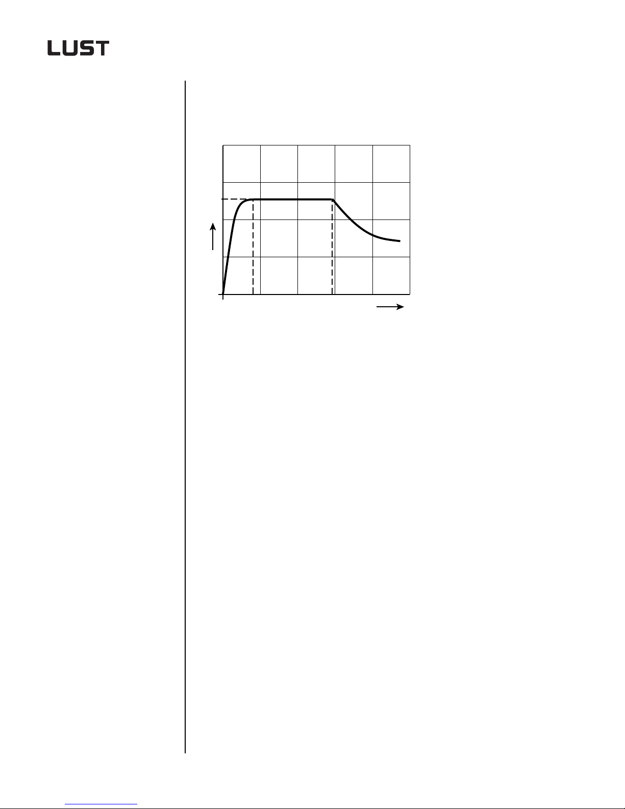
Speed manipulating range
The speed manipulating range is the range in which the motor can always
deliver nominal torque.
M
N
M
f
n
min
min
f
N
f (n)
n
N
Figure 1.12 Speed manipulating range
Manipulating range =
f
--------
f
min
N
--------- -=
n
n
N
min
fN Rated frequency in Hz
f
min
n
n
N
min
Minimum frequency in Hz
Nominal speed in rp m
Minimum sp eed in rpm
Engineering Guide CDA3000
1-14
Page 25
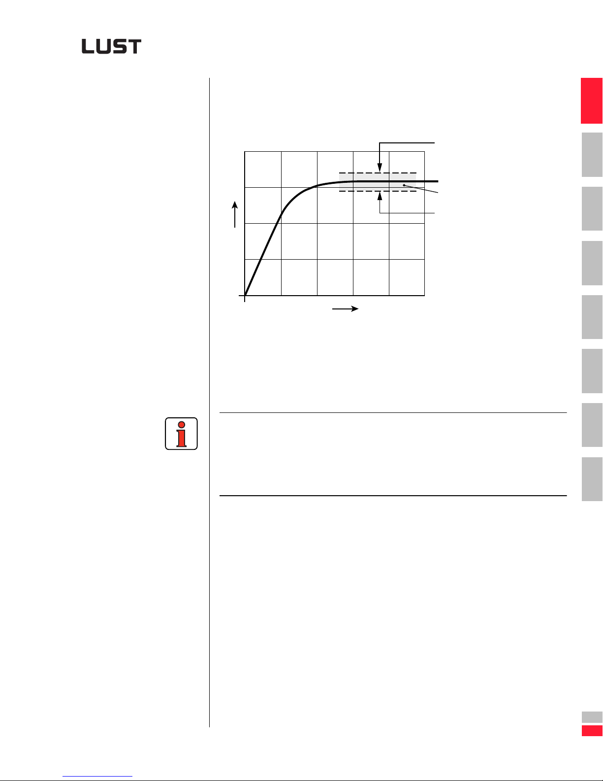
Static speed accuracy
1 Analysis of task
The static speed accuracy refers to the speed deviation in the steady
(static) state after completion of startup.
(2)
(3)
(1)
n
t
(1) Lower limit
(2) Upper limit
(3) Variation range
Figure 1.13 Static speed accuracy
1
2
3
4
5
6
In operation with speed cont rol a high-frequency r ipple is superimpose d
on the actual speed. The frequency of the ripple depends on the sampling
rate of the speed controller. The amplitude of the said ripple is dependent
on the encoder system used and on the mass iner tia sy stem (applicatio n
and motor).
7
A
Engineering Guide CDA3000
DE
EN
1-15
Page 26
1 Analysis of task
Dynamic speed accuracy
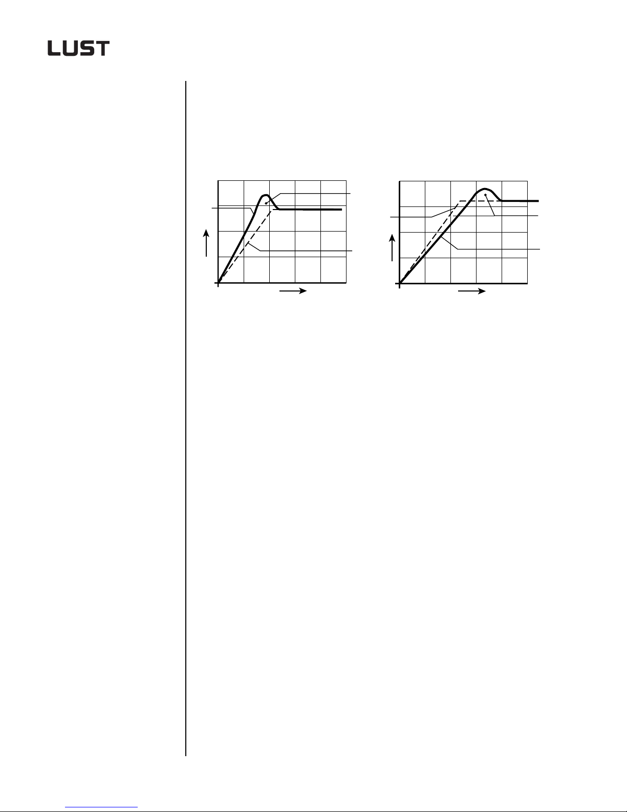
The dynamic speed accuracy refers to the speed deviation during the
startup or braking process of a speed change. The greatest deviation
very often occurs in the transient response in settling to the desired
speed.
(1)
(3)
(2)
(1)
(2)
n
t
(1) Dynamic variation
(2) Reference
(3) Actual
Figure 1.14 Dynamic speed accura cy
(3)
n
t
(1) Dynamic variation
(2) Reference
(3) Actual
Engineering Guide CDA3000
1-16
Page 27
1 Analysis of task
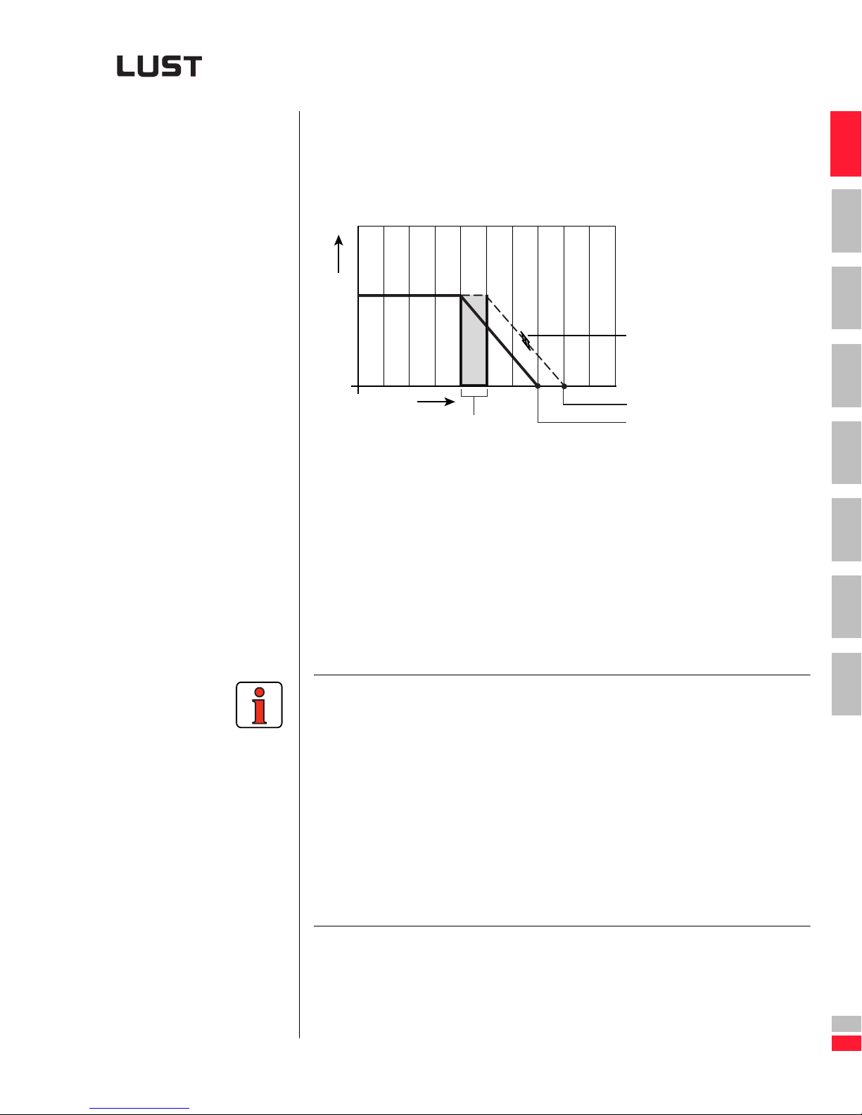
Positioning accuracy without position control (Start/Stop mode)
The term positioning accuracy refers to the position deviation at standstill.
The degree of deviation is decisively influenced by the r esponse times of
the control and the drive controller.
SF = V
Vmax.
t
(1)
(1) Scan cycle of control terminals on inverter (tRF=response error)
(2) Destination position 1 (stop signal comes together with read-in
of control signals on inverter)
(3) Destination position 2 (Stop signal comes directly after read-in of
control signals on inverter)
(4) Slip range (depending on control mode the braking ramp
is slipdependent)
SF = Positioning error
in mm
(4)
V
max
in mm/s
t
(3)
RF
(terminal
(2)
scan cycle) in s
. t
max
RF
= Velocity
= Response error
1
2
3
4
5
6
Engineering Guide CDA3000
Figure 1.15 Start/stop positioning
The positioning and repeat accuracy is of course also dependent on other
fact or s such as:
➢ Implement at ion of the mechanical function
➢ Mechanical system of the pickup
➢ Gearing used
➢ Constant response time of the control
➢ Measurement resolution from position transducer
➢ etc.
A precise analysis is only possible in specific cas es.
1-17
7
A
DE
EN
Page 28
1 Analysis of task
Positioning accuracy with position control
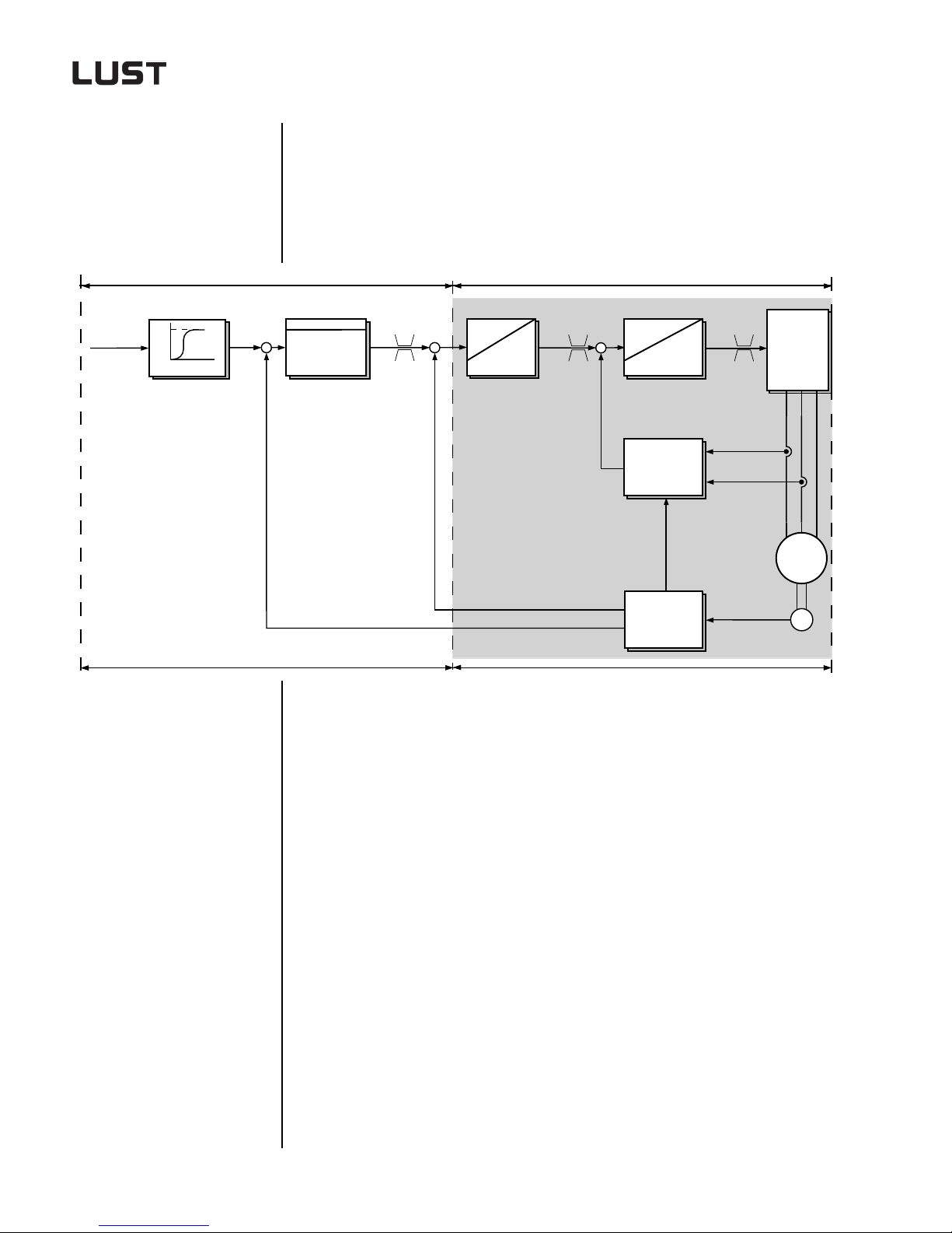
In the case of a position ing ope ration with pos ition c ontrol in the c ontrolle r,
the positioning accuracy is dependent on the encoder system and the quality of the position control (with or without pre-control, sampling time, etc.).
Destination
position
Control system
Reference generator
x
reference
Inverter modul CDA3000
-
Position controller
n
reference
m
reference
-
Speed
controller
m
n
x
-
actual
actual
actual
controller
Calculation
of flux and
momentum
Angle of
rotation
and speed
recording
Torque
ε
RS
U
reference
Modulator
uuu
i
a
i
b
Figure 1.16 Positioning with reference generator and position control in the
controller
and
PWR
c
a
b
M
3 ~
G
Encoder
Reference generator
The reference generator generates the characteristic over time of the
reference position.
Position controller
The position controller ensu res that the reference position is maint ained
as closely as possible.
Speed controller
The speed controller in turn ensures that the reference speed of the
motor is maintained.
Engineering Guide CDA3000
− The speed reference can be specified via +10 V to -10 V or via
CAN or PROFIBUS
1-18
Page 29
1.3.4 Load torque
1 Analysis of task
In summary: The positioning accuracy is dependent on the meas-
urement system and on the position control sampling.
It is also of course dependent on the sources of error
of the machine (temperature, rigidity, vibration, etc.).
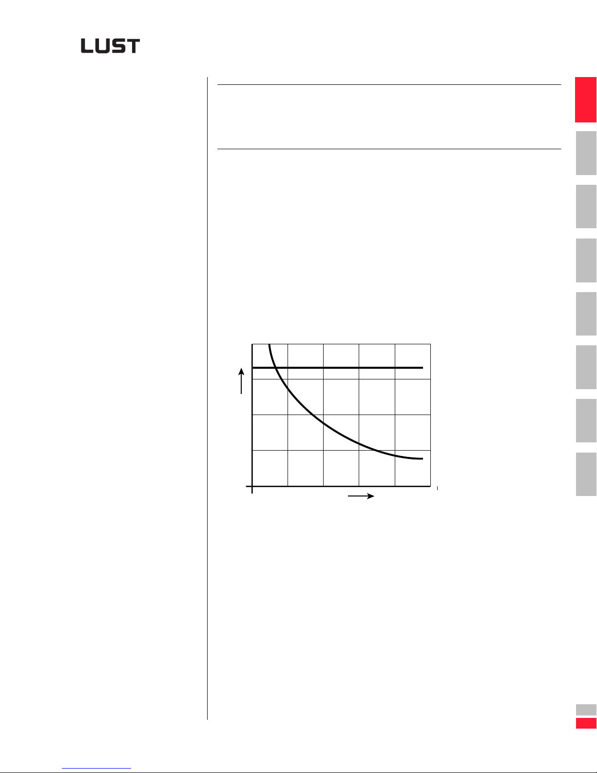
All machiner y counteracts th e drive with a specific torque. This torque is
composed of a static torque which is defined by the technological process
and the acceleration or deceleration tor que deter mined by the change of
speed and the inert mass.
The static torque is gen erally termed "load torque", and in m ost cases
acts opposing th e direction of motion. In exceptional cases, such as on
lifting gear durin g lowering, the loa d torqu e also acts in the direct ion of
motion.
1
2
3
4
Winders, coilers, lathes
P
ML,
P
M
n
Figure 1.17 Load characteristic: Winders, coilers, lathes
5
ML ~ 1/n
P = constant
6
7
A
Engineering Guide CDA3000
DE
EN
1-19
Page 30
1 Analysis of task
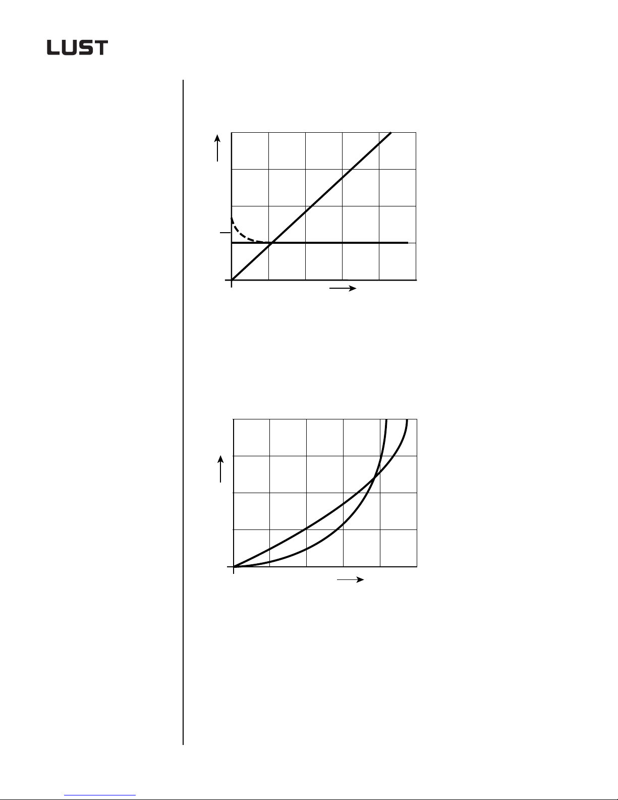
Lifting gear, conveyor systems, piston compressors, rolling
mills
P
ML = constant
P ~ n
M
ML,
P
L
(1)
n
(1) Break-away torque
Figure 1.18 Load characteristic: Lifting gear, conveyor systems, piston com-
pressors, rolling mills
Extruders
P
M
L
ML = f (n)
P = f (n)
Engineering Guide CDA3000
ML,
P
n
Figure 1.19 Load characteristic: Extruders
1-20
Page 31
1 Analysis of task
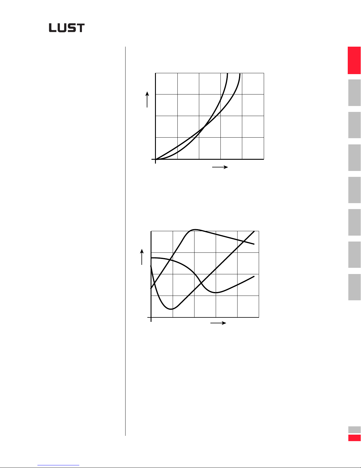
Blowers, fans, centrifugal pumps
M
P
L
ML,
P
n
Figure 1.20 Load characteristic: Blowers, fans, centrifugal pumps
Mills
(2)
ML ~ n²
P ~ n³
ML = f (n)
1
2
3
4
5
6
ML,
P
n
(1) Hammer mill
(2) Centrifugal mill
(3) Ball mill
Figure 1.21 Load characteristics: Mills
(3)
7
(1)
A
Engineering Guide CDA3000
DE
EN
1-21
Page 32
1 Analysis of task
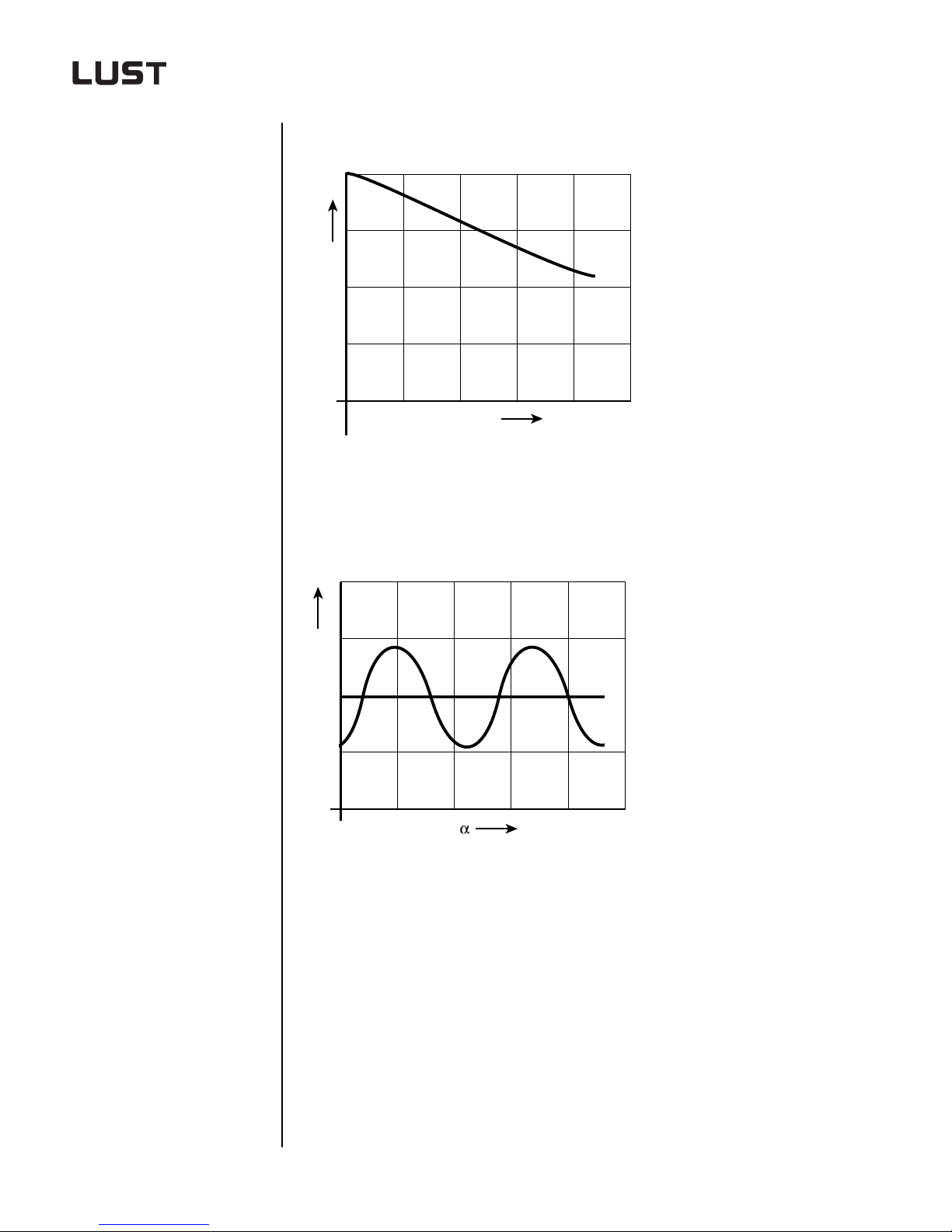
Conveyors such as inclined lifts
M
L
s
Figure 1.22 Load characteristic: Conveyors
ML = f (s)
Piston machines, eccentric presses, metal cutters
ML = f (α)
M
L
M
m
Figure 1.23 Load characteristic: Piston machines, eccentric presses, metal
cutters
Engineering Guide CDA3000
1-22
Page 33
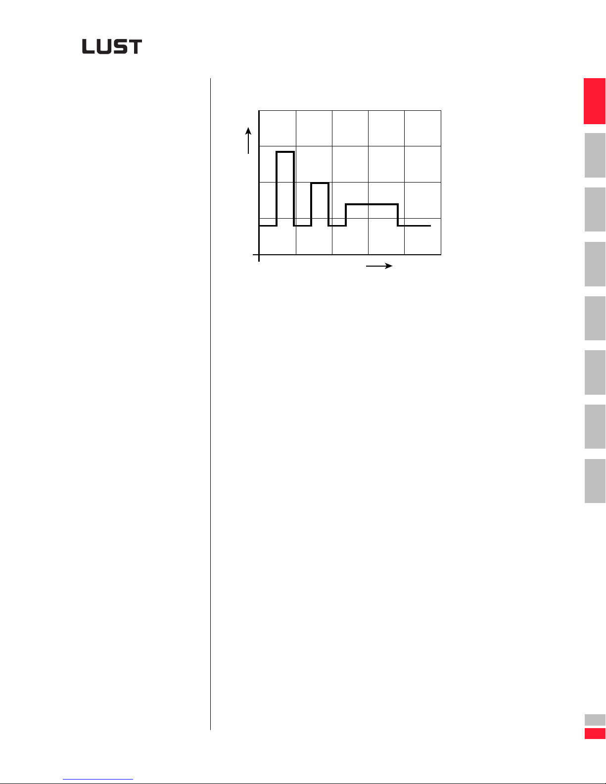
Machine tools
1 Analysis of task
M
L
t
Figure 1.24 Load characteristic: Machine tools
ML = f (t)
1
2
3
4
5
6
Engineering Guide CDA3000
7
A
DE
EN
1-23
Page 34
2 Drive definition
2.1 Recording of movement task ................................. 2-1
1
2
3
2.2 Drive definition via normogram ..............................2-6
2.2.1 Example of solution with four-pole motor ............2-7
2.2.2 Example of solution with six-pole motor ..............2-8
2.3 Drive definition via power rating ............................2-9
2.3.1 Example 1: Traction drive ..................................2-10
2.3.2 Example 2: Lifting drive .....................................2-12
2.4 Drive definition via L
2.4.1 Example 1: Trolley drive for gantry crane ...........2-15
2.4.2 Example 2: Belt turning station for
truck engine distribution .................... ................2-20
2.5 Selection of motor .................................................2-24
2.5.1 Characteristic values of standard three-phase
AC motors ..........................................................2-26
2.5.2 Characteristic values of asynchronous
servomotors ASx ............................................... 2-35
2.5.3 Characteristic values of reluctance motors .........2-41
UDRIVE PC PROGRAM .............. 2-13
4
5
6
7
A
Engineering Guide CDA3000
2.5.4 Characteristic values of synchronous motors .....2-44
2.5.5 Characteristic values of high-frequency motors ..2-47
2.6 Selection of gearing ..............................................2-48
2.6.1 Transmission gear .............................................2-48
2.6.2 Characteristic values of standard gears ..............2-49
2.6.3 Characteristic values of planetary gears .............2-49
DE
EN
2-1
Page 35
2 Drive definition
The goal must be realistic
Key limits must be kno w n
2.1 Recording of
movement task
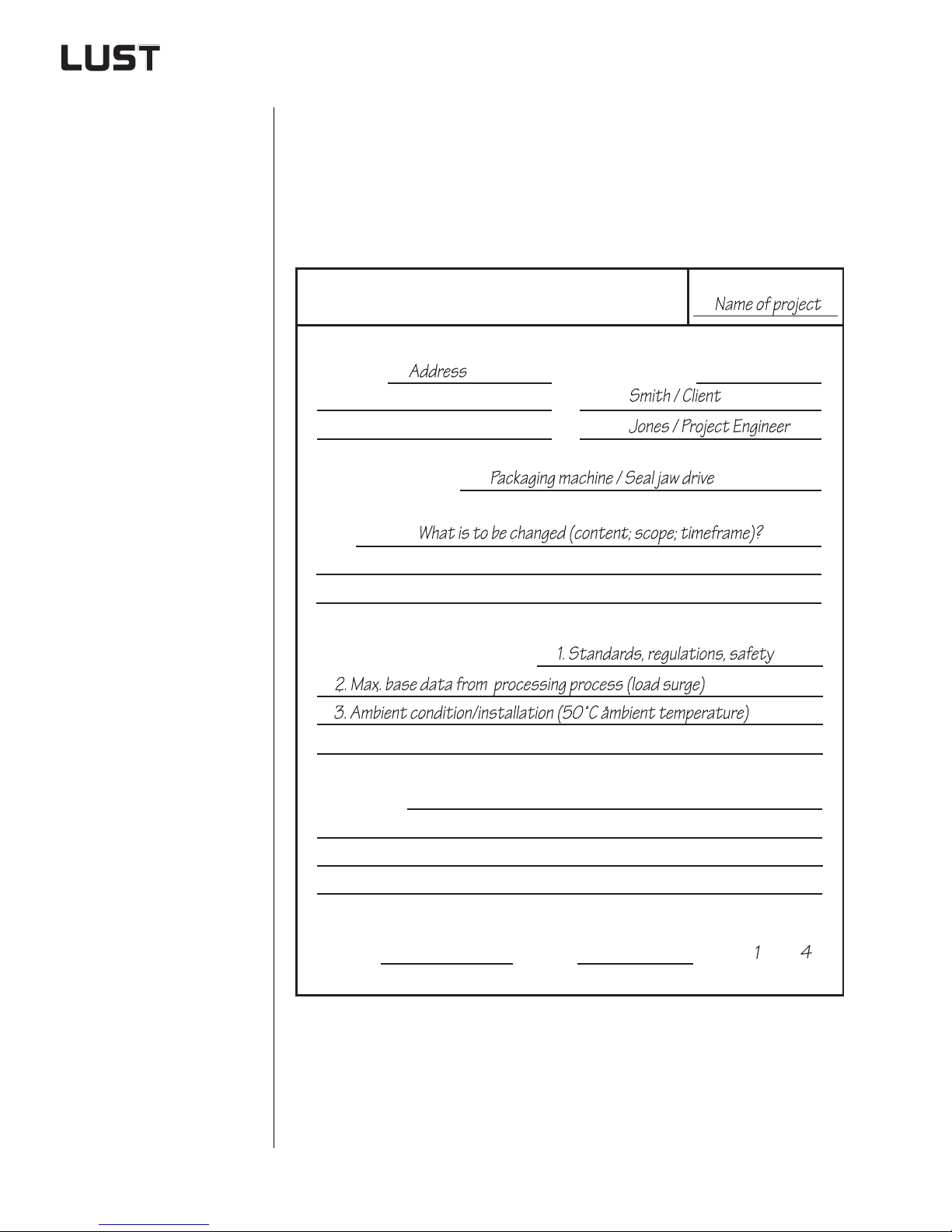
his process involves the description of the movement task in the processing process. For information on the basics of this subjec t
See section 1.
The procedure proposed in the following does not claim to be generally
applicable to all move ment tasks. It is merely intended to illustrate a possible procedure which can be applied with little labor commitment.
Recording of movement task
Company:
Industry/Application:
Goal:
Name/Function:
Project name::
Special background conditions:
Comments:
Author:
Date:
Sheet ..... of .....
You will find the copy template in the appendix under "Practical working
aids for the project engineer".
Engineering Guide CDA3000
2-2
Page 36
2 Drive definition
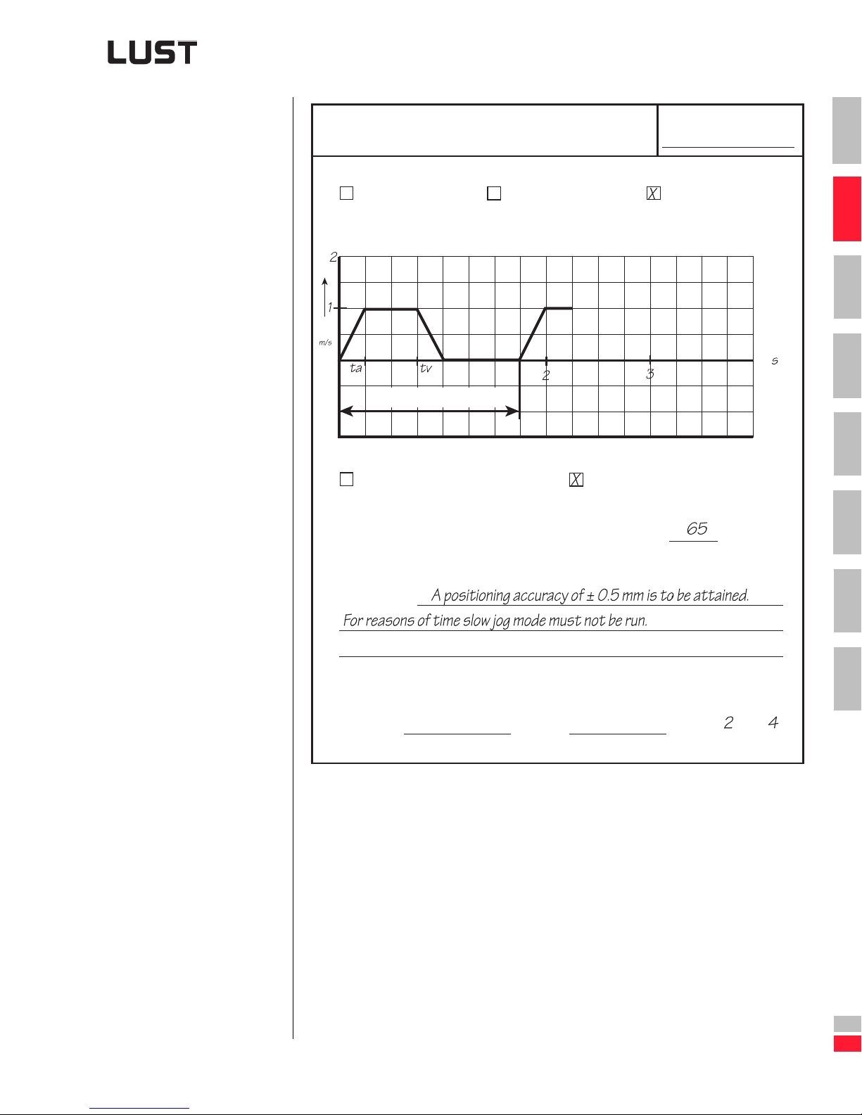
Movement requirement
v
[ ]
Movement requirement
for processing
Continuous
material flow
1
Discontinuous
batch process
T=Period
Rotational movement [n=f(t)]
Project name:
1
Discontinuous
unit process
2
3
t [ ]
4
5
Translational movement [v=f(t)]
Radius of drive shaft by which the movement is generated: mm
Comments:
Author:
For definitions of terms in this context See section 1.3.
You will find the copy template in the appendix u nder "Practical working
aids for the project engineer".
Date:
Sheet ..... of .....
6
7
A
Engineering Guide CDA3000
DE
EN
2-3
Page 37
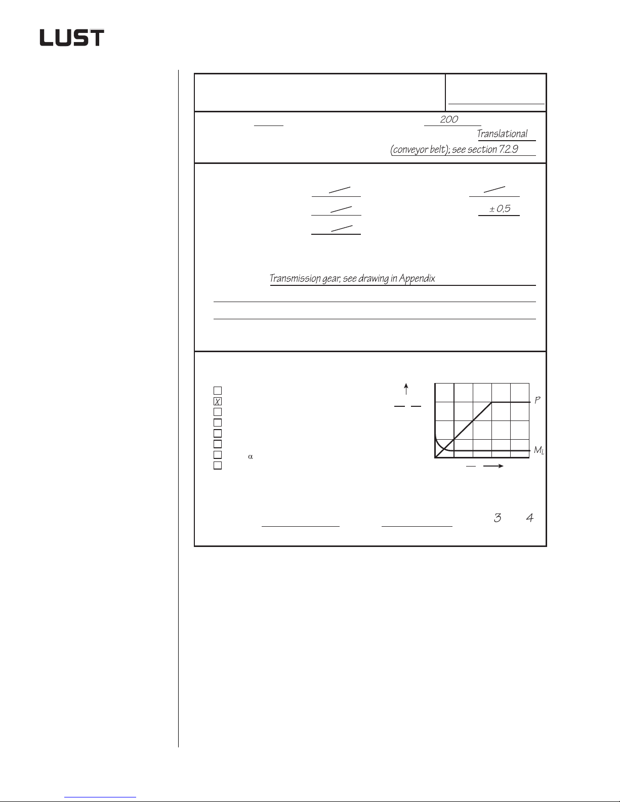
2 Drive definition
Movement requirement
Movement requirement
for processing
Moment : [kgm²]
of inertia
Speed manipulating range:
Static speed accuracy:
Dynamic speed accuracy:
Comments:
or
Mass: [kg]
Mode of movement:
Torque rise time:
[rpm]
[rpm]
Positioning accuracy:
Project name:
[ms]
[ms]
Load torque of processing process
ML~ 1/n, P=constant
=constant, P~n
M
L
=f(n), P=f(n)
M
L
~n², P~n³
M
L
=f(n)
M
L
=f(s)
M
L
=f( )
M
L
=f(t)
M
L
Author:
Date:
ML, P
P
M
N
1,5
N
1,0
0,5
n
n
n
Sheet ..... of .....
For definitions of terms in this cont ext see section 1. 3.
You will find the copy template in the appendix under "Practical working
aids for the project engineer".
Engineering Guide CDA3000
2-4
Page 38
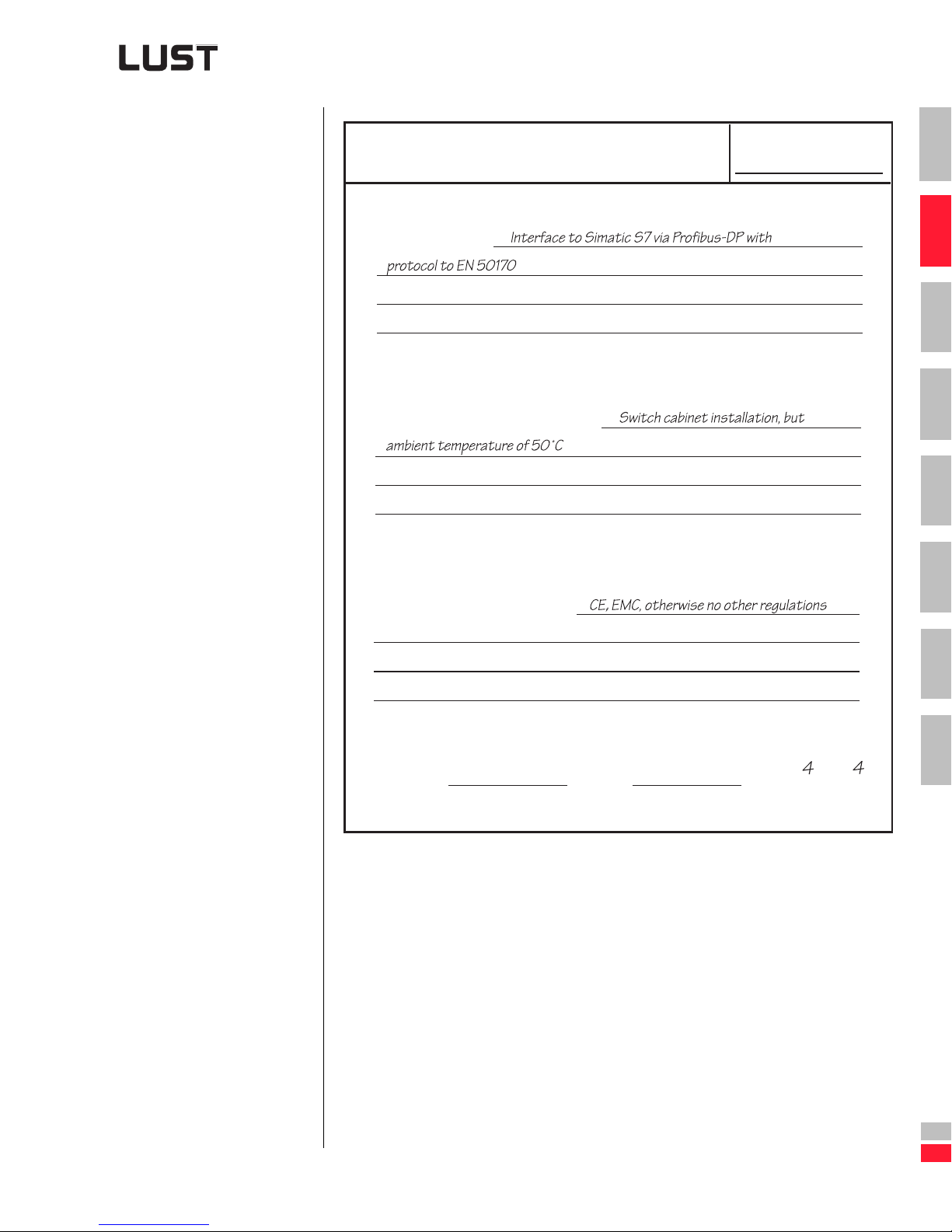
2 Drive definition
Additional environmental data
Project name:
1
System interface
➢ Automate
➢ Environment
➢ Standards
Automation process:
Environmental and installation conditions:
Standards, regulations and safety:
2
3
4
5
6
7
Engineering Guide CDA3000
Author:
You will find the copy template in the appendix u nder "Practical working
aids for the project engineer".
Date:
2-5
Sheet ..... of .....
A
DE
EN
Page 39
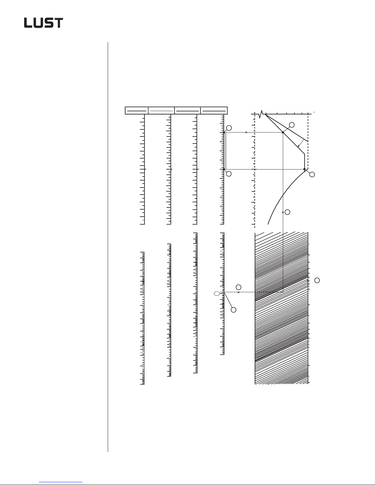
2 Drive definition
2.2 Drive definition
via normogram
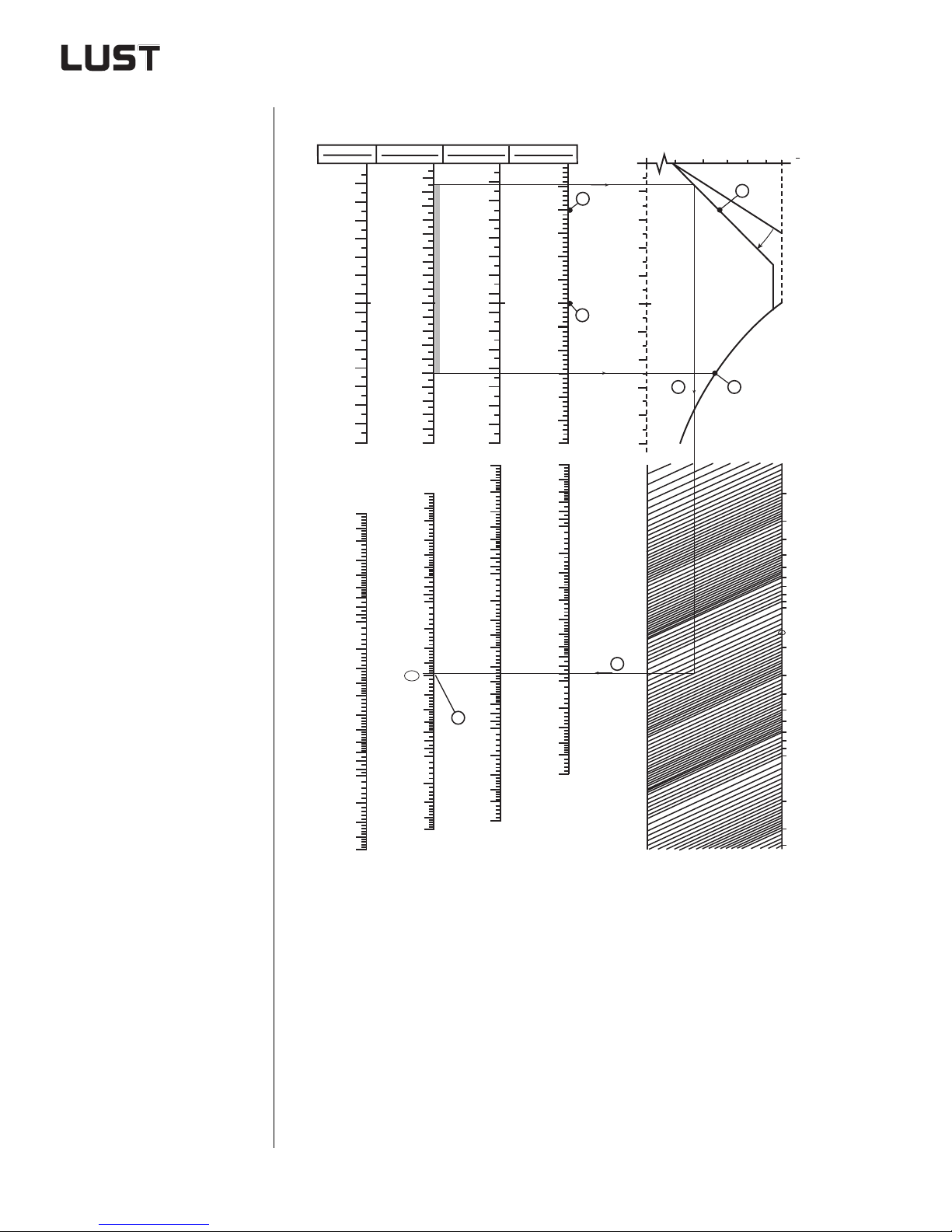
Using the normogram:
1. Plot the speed vertices
for the relevant motor.
2. Draw two straight lines
to the continuous load
characteristic.
3. Connect the lowest
point on the continuous
load characteristic to
the load torque by a
straight line.
4. Connect the load torque to the rated power
by a straight line.
5. Select your product
based on the performance rating data.
he normogram provides user-friendly graphical power ratings for
applications with IEC standard motor. It is primarily used to define the
power outputs of rotational drives such as winders, mills, extruders, centrifuges, mixers, etc. Any break-away torques or load surges occurring
must be calculated separately.
Engine speeds
750 rpm
8-pole
100
200
300
400
500
600
700
750
800
900
1000
1100
1200
1300
1400
1500
2
2,5
3
4
5
6
7
8
9
10
15
20
25
30
40
50
60
70
80
90
100
150
200
250
300
1000 rpm
6-pole
1000
1200
1400
1600
1800
2000
10
15
20
25
30
40
50
60
70
80
90
100
150
200
250
300
1500 rpm
4-pole
200
400
600
800
2
2,5
3
4
5
6
7
8
9
200
400
600
800
1000
1200
1400
1500
1600
1800
2000
2200
2400
2600
2800
3000
2
2,5
3
4
5
6
7
8
9
10
15
20
25
30
40
50
60
70
80
90
100
150
200
250
300
400
P
[kW]
N UR
Rated power, inverter and motor
3000 rpm
2-pole
500
1000
1500
2000
2500
3000
3500
4000
4500
5000
5500
6000
10
15
20
25
30
40
50
60
70
80
90
100
150
200
250
300
400
1.
1.
n [rpm]
4
5
6
7
8
9
Continuous load characteristic in
inverter operation with IEC standard motor
10
20
30
40
0,5
0,6 0,7 0,8
50
60
70
80
90
f [Hz]
100
4.
5.
6
Load torque
0,9 1,0
M
M
M UR
2.
P >
2.
3.
10
20
30
40
50
60
70
80
90
100
200
300
400
500
600
700
800
900
1000
2000
3000
4000
M
[Nm]
You will find the copy template in the appendix under "Practical working
aids for the project engineer". Continuous load ch aracteristic - See section 2.5.1.
Engineering Guide CDA3000
2-6
Page 40
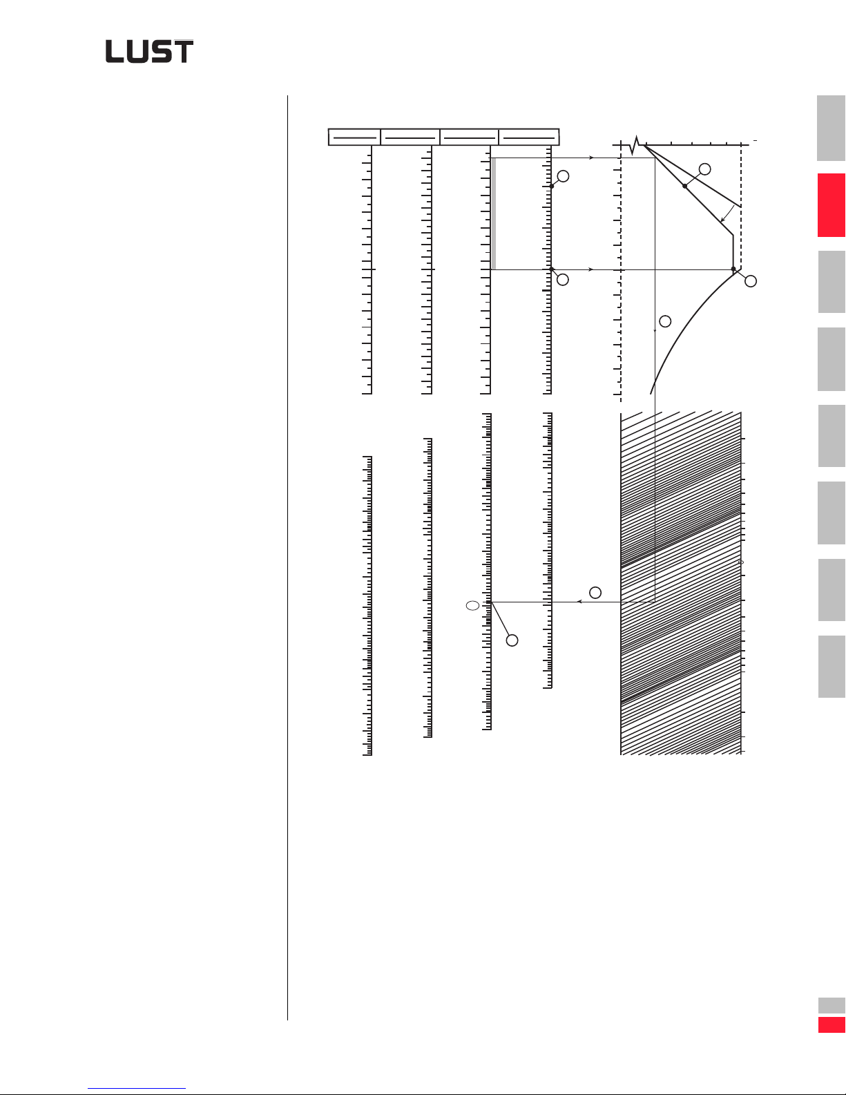
2 Drive definition
Requirement:
n
1
= 150 rpm
n
2
= 1500 rpm
M
1
= M2 = 150 Nm
External ventilation
not permitted.
2.2.1 Example of
solution with
four-pole motor
Engine speeds
750 rpm
8-pole
100
200
300
400
500
600
700
750
800
900
1000
1100
1200
1300
1400
1500
2
2,5
3
4
5
6
7
8
9
10
15
20
25
30
40
50
60
70
80
90
100
150
200
250
300
1000 rpm
6-pole
1000
1200
1400
1600
1800
2000
20
30
100
150
200
250
300
1500 rpm
4-pole
200
400
600
800
2
2,5
3
4
5
6
7
8
9
10
15
25
40
50
60
70
80
90
200
400
600
800
1000
1200
1400
1500
1600
1800
2000
2200
2400
2600
2800
3000
2
2,5
3
4
5
6
7
8
9
10
15
20
25
30
40
50
60
70
80
90
100
150
200
250
300
400
P
[kW]
N UR
Rated power, inverter and motor
3000 rpm
2-pole
1000
1500
2000
3000
3500
4000
5000
5.
2500
4500
5500
6000
100
150
200
250
300
400
Continuous load characteristic in
inverter operation
500
1.
1.
n [rpm]
4
5
6
7
8
9
10
15
20
25
30
40
50
60
70
80
90
10
20
30
40
50
60
70
80
90
100
4.
f [Hz]
0,5
6
0,6 0,7 0,8
3.
0,9 1,0
M
M
M UR
2.
P >
1
2
2.
3
4
10
20
5
6
7
1000
30
40
50
60
70
80
90
100
200
300
400
500
600
700
800
900
A
2000
3000
4000
M
Load torque
[Nm]
Engineering Guide CDA3000
Solution:
The rated power of the motor (four-pole) and the inverter is 50 kW.
DE
EN
2-7
Page 41
2 Drive definition
2.2.2 Example of
solution with
six-pole motor
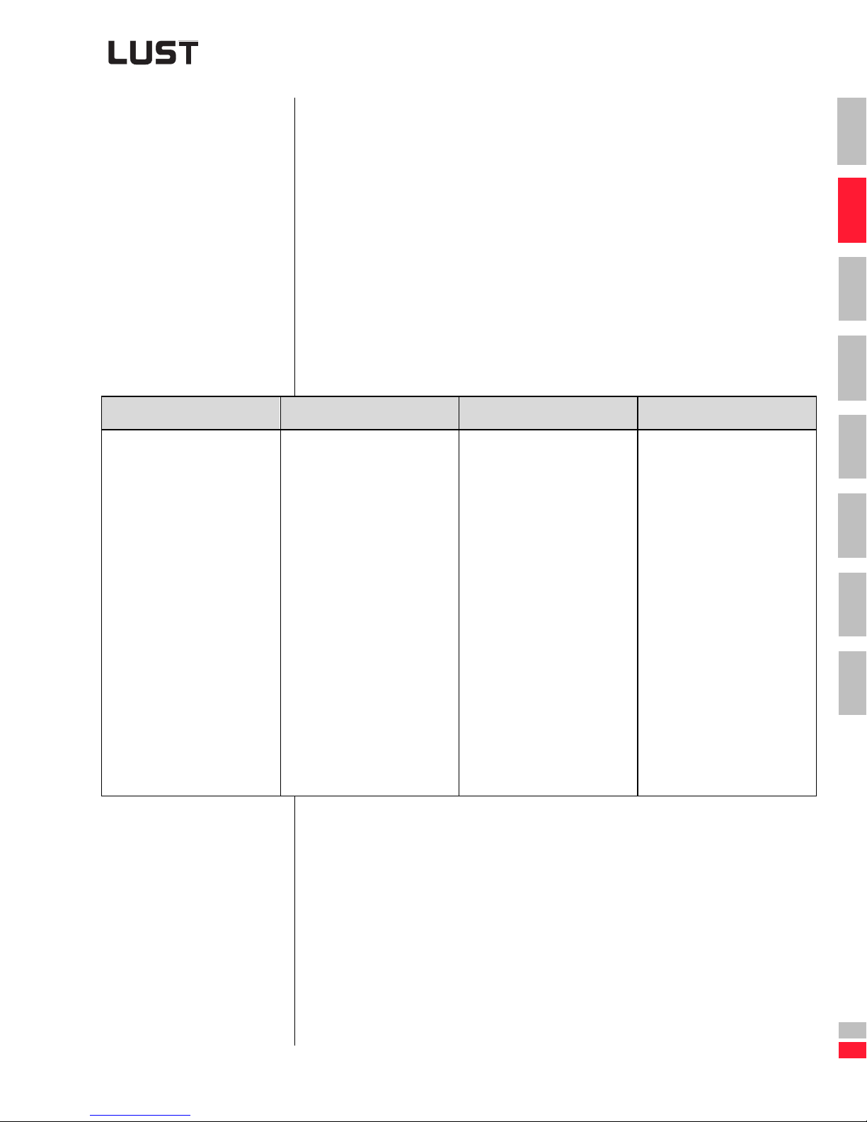
Requirement:
= 150 rpm
n
1
= 1500 rpm
n
2
M
= M2 = 150 Nm
1
External ventilation
not permitted.
Engine speeds
750 rpm
8-pole
100
200
300
400
500
600
700
750
800
900
1000
1100
1200
1300
1400
1500
10
15
20
25
30
40
50
60
70
80
90
100
150
200
250
300
1000 rpm
6-pole
1000
1200
1400
1600
1800
2000
2
2,5
3
4
5
6
7
8
9
10
15
20
25
30
40
50
60
70
80
90
100
150
200
250
300
1500 rpm
4-pole
200
400
600
800
2
2,5
3
4
5
6
7
8
9
200
400
600
800
1000
1200
1400
1500
1600
1800
2000
2200
2400
2600
2800
3000
10
15
20
25
30
40
50
60
70
80
5.
90
100
150
200
250
300
400
P
[kW]
N UR
3000 rpm
2-pole
500
1.
1000
1500
2000
2500
3000
1.
3500
4000
4500
5000
5500
n [rpm]
6000
2
2,5
3
4
5
6
7
8
9
4
5
6
7
8
9
10
15
20
25
30
40
50
60
70
80
90
100
150
200
250
300
400
Rated power, inverter and motor
Continuous load characteristic in
inverter operation
10
20
30
40
0,5
0,6 0,7 0,8
50
60
70
3.
80
90
f [Hz]
100
6
4.
Load torque
0,9 1,0
M
M
M UR
2.
P >
2.
10
20
30
40
50
60
70
80
90
100
200
300
400
500
600
700
800
900
1000
2000
3000
4000
M
[Nm]
Solution:
The rated power of the motor (six-pole) and the inverter is 30 kW.
Engineering Guide CDA3000
2-8
Page 42
2 Drive definition
T
2.3 Drive definition
via power rating
Packaging machinery Manipulators Conveyor systems General engineering
• Discharge drive
(cladding removal,
vacuum packing
sheet feed)
• Metering drive
(volume me tering,
screw-type metering)
• Traction/lifting axis
(packers, palletizers)
• Belt drive (bucket
conveyor, product
loading belt)
• Labeling machine
(X/Y drive)
• Traveling axis,
• Lifting axis, Y-axis
• Indexing table drive
• Gripper drive
•etc.
he method of power rating is principally used in three areas of application:
1. Metalworking machinery (milling, drilling, grinding, etc.)
2. Process engin eering (pumps/fans, extruder, etc.)
3. General engineering (packaging and special machinery , manipula-
tors and conveyor systems, etc.)
The equations relating t o areas of applica tion 1 and 2 and the ir application are describe d in Appendix A.2.2.
The following deals with area of application 3 and thus with the design of
traction and lifting drives.
X/Z-axis
• Trolley drive with
1, 2 and 4 motors
• Crane lifting gear,
trolley and running
gear
• Conveyor belt
• Door drive
• Shelf conveyor
• Parquet flooring
conveyor belt
• Roller and chain
drive
•etc.
• Metalworking
machinery
• Cross-cutters
• All kinds of special
machinery
•etc.
1
2
3
4
5
6
7
A
•etc.
Engineering Guide CDA3000
Table 2.1 Typical ex amples of power rat i ng from area of application 3
DE
EN
2-9
Page 43
2 Drive definition
2.3.1 Example 1:
Traction drive
Example: Z-axis of a manipulator
m = 51.5 kg
a = 3 m/s
2
v = 1.5 m/s
η = 0.88
ta = 0.5
µ = 0.01
1. Determine power requirement to move the application
mav⋅⋅
------------------
P
a
P
F
P
FahrPaPF
η
mgµ v⋅⋅⋅
--------------------------
51 5 kg, 3m s2⁄ 15ms⁄,⋅⋅
-------------------------------------------------------------- -
088,
51 5kg, 98mss⁄, 001, 15ms⁄,⋅⋅⋅
------------------------------------------------------------------------------------
η
273W=+=
088,
264W===
9W===
2. Select motor
The selected motor must have a power rating higher than P
Drive
the motor from the list.
. Select
Selected motor: Type 71L/4, 370W, JM = 0.00073 kgm
The motor is to be run at max. 2000 rpm
(70 Hz characteri stic).
2
JMn
⋅
P
aR
M
------------------- -
91 2, ta⋅
, 20002min
0 00073kgm
------------------------------------------------------------------ 65W== =
2
91 2, 05,⋅
⋅
1–
3. Calculate gross output
P
= Pa + PF + PaR = 264W + 9W + 65W = 338W
Gross
For more details on “Selection of inv erter modules” refer to sections 3.3 to
3.6.
Engineering Guide CDA3000
2-10
Page 44
2 Drive definition
Abbreviations used
P
a
P
aR
P
P
m Total mass [kg]
a Acceleration [m/s²]
v Velocity [ms]
µ Tractive resistance/Coefficient of friction
η Efficiency of the drive solution
g Acceleration due to gravity [9.8m/s²]
J
M
n
M
t
a
For a list of standard three-phas e AC motors See section A.2.11 Motor
list.
Asynchronous motors See section 2.5.2.
Power to accelerate the load [W]
Power to accelerate the rotor [W]
Power to overcome the
F
tractive resistance/friction [W]
Power to lift the load [W]
H
Moment of inertia of the selected motor [kgm²]
Max. speed of the selected motor [rpm]
Acceleration time [s]
1
2
3
4
5
6
7
A
Engineering Guide CDA3000
DE
EN
2-11
Page 45

2 Drive definition
2.3.2 Example 2:
Lifting drive
Example: Z-axis of a manipulator
m = 2.5 kg
a = 10 m/s
v = 1.5 m/s
2
η = 0.88
ta = 0.15
µ = 0.01
1. Determine power requirement to move the application
mav⋅⋅
------------------
P
a
P
F
P
H
P
LiftPaPFPH
η
mgµ v⋅⋅⋅
--------------------------
mgv⋅⋅
------------------
η
25kg, 10m s2⁄ 15ms⁄,⋅⋅
-------------------------------------------------------------- -
088,
25kg, 98m ss⁄, 001, 15ms⁄,⋅⋅⋅
--------------------------------------------------------------------------------- -
η
25kg, 98mss⁄, 15m s⁄,⋅⋅
-----------------------------------------------------------------
088,
86W=++=
088,
43W===
1W===
42W===
2. Select motor
The selected motor must have a power rating higher tha n P
. Select the
Lift
motor from the list.
Selected motor:
Type 71S/4, 250W, IM = 0.00056 kgm
2
The motor is to be run at max. 2000 rpm
(70 Hz characteri stic).
2
JMn
⋅
P
aR
M
------------------- -
⋅
91 2, t
, 20002min
0 00056kgm
------------------------------------------------------------------ 164W== =
a
91 2, 015,⋅
2
⋅
1–
3. Calculate gross output
P
= Pa + PF + PH + PaR = 43W + 1W + 42W + 164W= 250W
Gross
For more details on “Selection of inv erter modules” refer to sections 3.3 to
3.6.
Engineering Guide CDA3000
2-12
Page 46
2 Drive definition
2.4 Drive definition
via L
UDRIVE
PROGRAM
PC
he LUDRIVE drive calculation program meets the wishes of many
users for quick and easy calculation of the various drive solutions.
T
The drive program is divided into two sections.
The first section conta ins a formula bank with 38 formulae for calculation
of:
• Moments of inertia of various bodies
• Moments of inertia of applications
• v/t diagrams
• Tractive re sistances and friction moments
• Effective torque loads
• Various drive capacit i es
• Drive torques
With the aid of the second section complete drive units can be configured.
The drive data are entere d in a practice-or iented s equence. This secon d
section supports the design of:
• Horizontal traction drives
• Traction drives with rise for upward movement
1
2
3
4
5
• Traction drives with rise for downward movement
• Lifting drives without counterweight (lifting)
• Lifting drives wit hout counterweight (lowering)
• Indexing tables with ball rim
• Indexing tables wi th shaft through the center point
• Spindle drives
• Rotationa l drives
After calculating the drive L
shows the character istic of the me an torque, the sp eed and the moment
over time. Based on this graph, the behavior of the drive solutions in practical applications can be assessed. Of course, all influencing factors
such as the rotor moment of inertia of the motor, the field weakening
range, the nominal winding point of the motor etc. are ana ly zed and /or
calculated and translated onto the graph.
In addition to the f unctions described, the L
ports ancillary functions such as Help, Print, Save and Load.
Note: The LUDRIVE drive program is based on the theoretical prin-
ciples of the book entitled “Das 1x1 de r Antriebsauslegung”
(“The ABC of drive design”) - see "Bibliography and source
reference".
UDRIVE displays a graph on the PC. The graph
UDRIVE program also sup-
6
7
A
Engineering Guide CDA3000
DE
EN
2-13
Page 47
2 Drive definition
Where can you get LUDRIVE?
You can download the LUDRIVE dr ive design program for MS-DOS™ ver-
®
sion 1.6 (viable under Windows
95) free of charge from our website:
http://www.lust-tec.de/produkte.
The program is easily controlled from the keyboard. The DOS user
interface provides access to calculation formulae which have been tried
and proven over decades of practical application.
Please note that the software LUDRIVE is only available in german language.
Network printing
When printing from DOS applications under Windows®95 in network
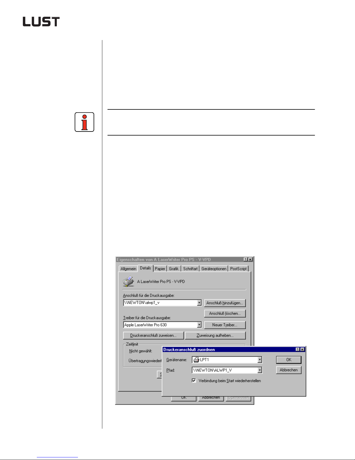
mode, the printer must be assigned to the parallel port LTP1.
From the “Start menu choose Settings > Printers”, select the printer
you want to use and click with the right mouse button to open the “Pro-
perti es” dialog box.
On the “Details” tab click on the “Capture Printer Port” button.
Make sure that data to be printed to LTP1 are diverted to the network
printer - See Figure 2.1.
Figure 2.1 The network printer must be ass i gned to the parallel port LTP1
Engineering Guide CDA3000
2-14
Page 48
2 Drive definition
2.4.1 Example 1:
Trolley drive for
gantry crane
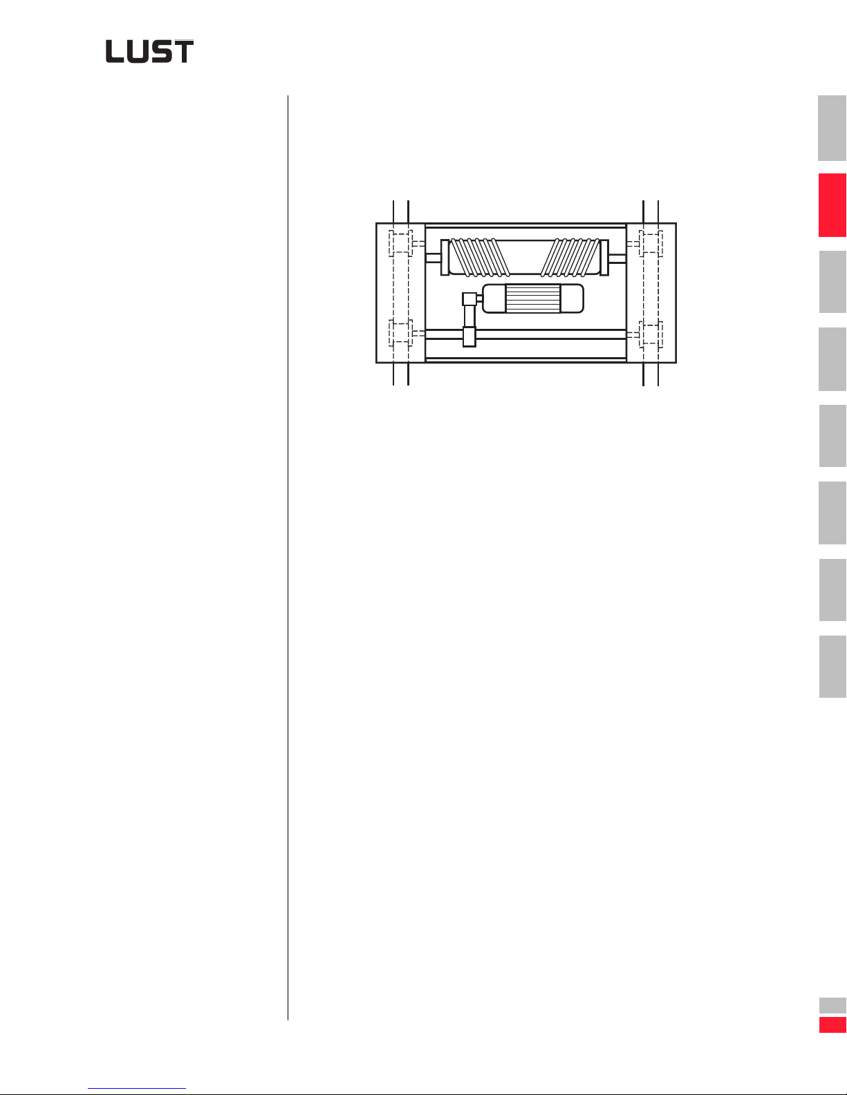
Because of the narrow track width the trolley has a central drive powering
a running wheel on each side. The r unning wheels ar e coupled togethe r
by a shaft. The drive system is a four-pole helical gearbox motor with
brake.
Figure 2.2 Standard trolley drive with geared motor
Known data:
Intrinsic weight of the trolley 5 t
Lifting weight 10 t
Running speed 30 m/min.
Two wheels are driven
Wheel diameter 315 mm
Journal diameter 80 mm
Friction pairing (rail/wheel)Steel/steel
Transmission gear z1=18
z2=34
Efficiency of the drive 80%
Mass moment of iner tia of the running wheels
and the shaft 0.85 kgm²
Acceleration and braking time 1.5 s
Max. factor for starting torque 1.25
1
2
3
4
5
6
7
A
Engineering Guide CDA3000
DE
EN
2-15
Page 49
Steps in drive design
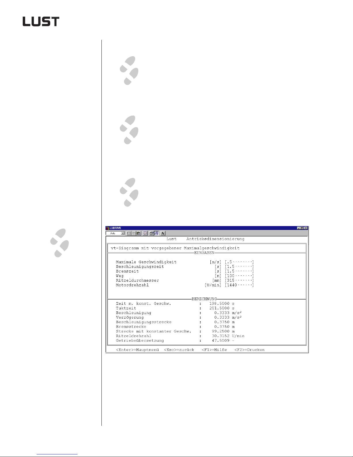
1.
2.
3.
1.
Calculate acceleration and deceleration by means
of “v/t diagram” program section.
Calculate longitudinal coefficient of friction bet ween
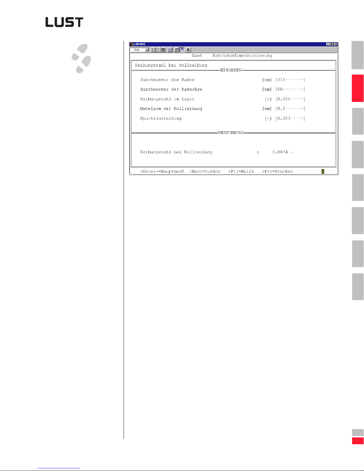
rail and wheel by means of “Tractive resistance/Friction moment” program section.
Calculate drive capacity by means of “Drive calculation/Traction drive” program section.
2 Drive definition
a) for max. motor speed 1440 rpm
b) for max. motor speed 2000 rpm
Figure 2.3 Drive design with LUDRIVE
Engineering Guide CDA3000
2-16
Page 50
2 Drive definition
2.
Figure 2.4 Tractive/frictional resistance
1
2
3
4
5
6
7
A
Engineering Guide CDA3000
DE
EN
2-17
Page 51
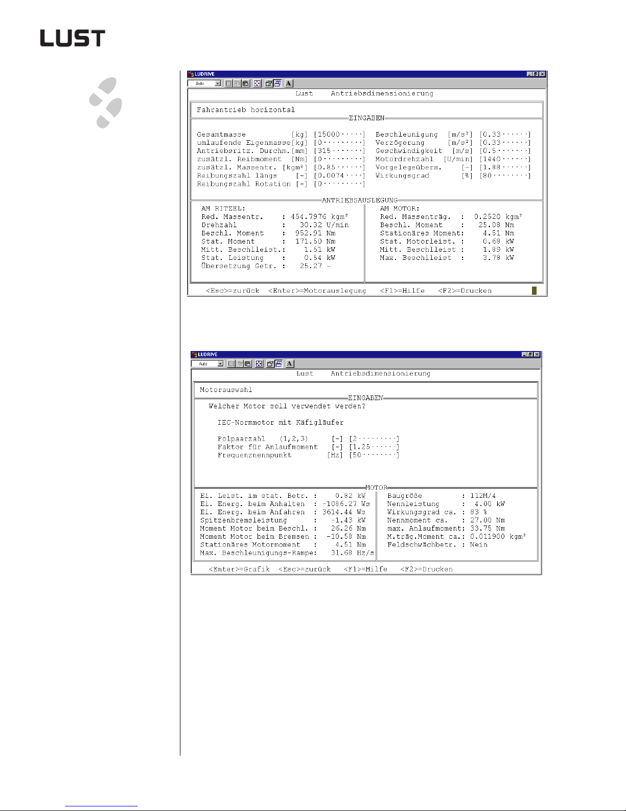
Figure 2.5 Drive capacit y
3.
Max. motor speed
1440 rpm
2 Drive definition
Figure 2.6 Motor selection
Engineering Guide CDA3000
2-18
Page 52
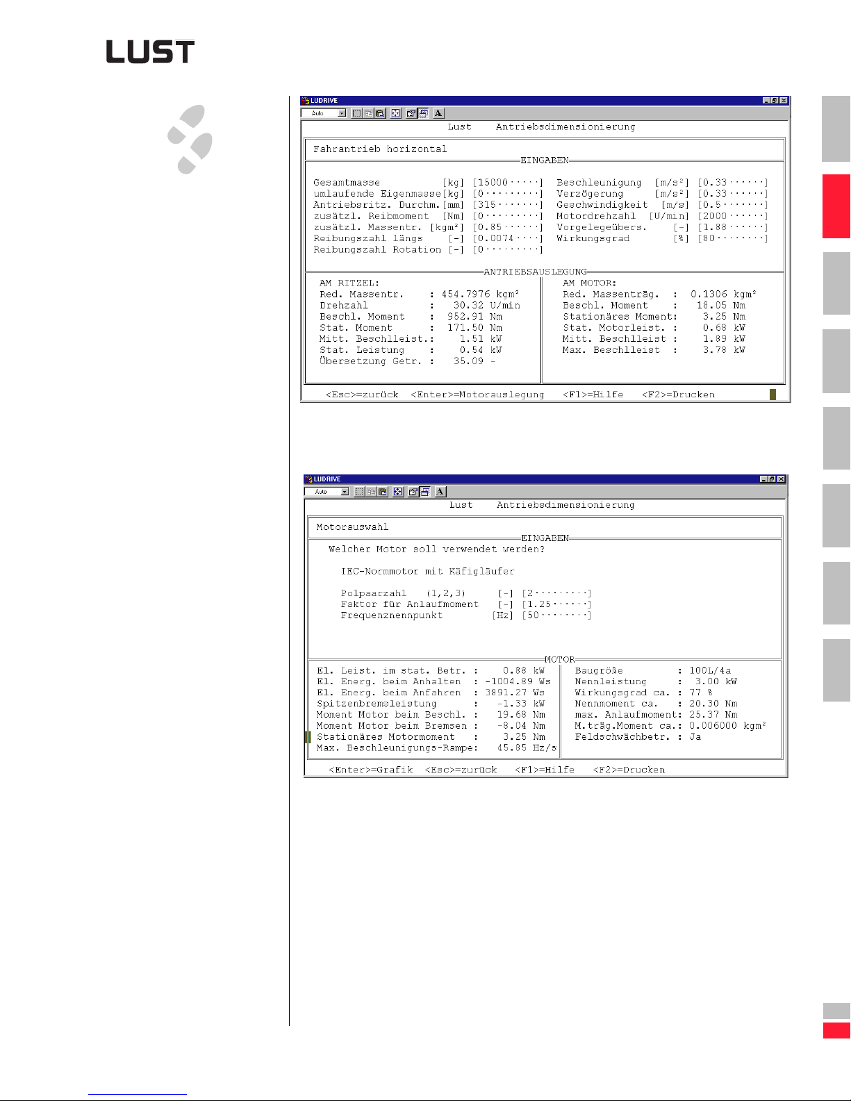
Figure 2.7 Drive capacity
Max. motor speed
2000 rpm
3.
2 Drive definition
1
2
3
4
Figure 2.8 Motor selection
5
6
7
A
Engineering Guide CDA3000
DE
EN
2-19
Page 53
2 Drive definition
2.4.2 Example 2: Belt
turning station
for truck engine
distribution
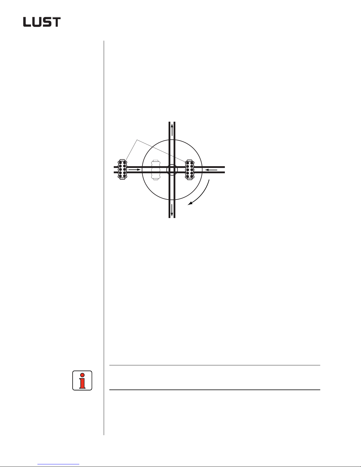
The indexing table for the belt turning sta tion is des igned to distr i bute the
truck engines across two different conveyor belts. The indexing table is
incremented in steps of 90°.
The rotating upper section is supported by a slewing ring. Slewing rings
permit a highly co mpact design combined with a low center of gravity
(only one bearing to absorb all forces and moments).
The size of the bearing support means that correspondingly very high
radial and axial forces and moments are absorbed.
(1)
(1) Truck engines
Figure 2.9 Belt turning station
Known data:
Mass of indexing table with slewing ring etc. 130 kg
Indexing table diameter 1600 mm
Mass of truck engine 500 kg
Distance of truck from pivot point 600 mm
Max. cycle time for 90° 1.4 s
Acceleration/deceleration ti me 0.2 s
Ball rim z1=29
z2=180
Efficiency 90%
Motor nominal speed 1440 rpm
Positioning accuracy need only be approx. ± 2 mm, because mechanical
indices are used.
Engineering Guide CDA3000
2-20
Page 54
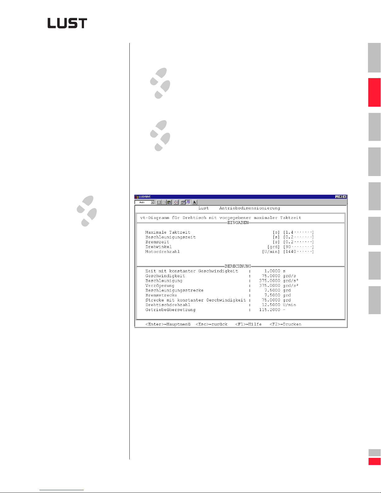
Steps in drive design
Calculate rotational velocity, rotational acceleration
1.
2.
and rotational deceleration by means of “v/ t diagram for indexing table ” program section.
Calculate drive capacity by means of “Drive calculation / Indexing table with slewing rin g” program sec tion.
a. Startup factor 1.25 typical values with
b. Star tup factor 2 typical values with Sensor-
2 Drive definition
1
2
3
Voltage Frequency Control (VFC)
4
less Flux Control (SFC)
1.
5
6
7
A
Figure 2.10 v/t diagrams
Engineering Guide CDA3000
DE
EN
2-21
Page 55
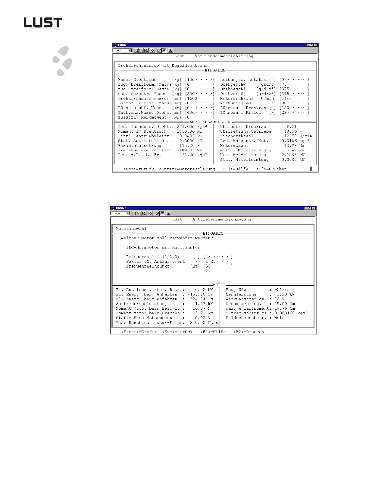
Figure 2.11 Calculation
2.
25% motor overload
with VFC
Factor for starting torque = 1.25
(1.25
.
MN)
2 Drive definition
Engineering Guide CDA3000
Figure 2.12 Motor selection
2-22
Page 56
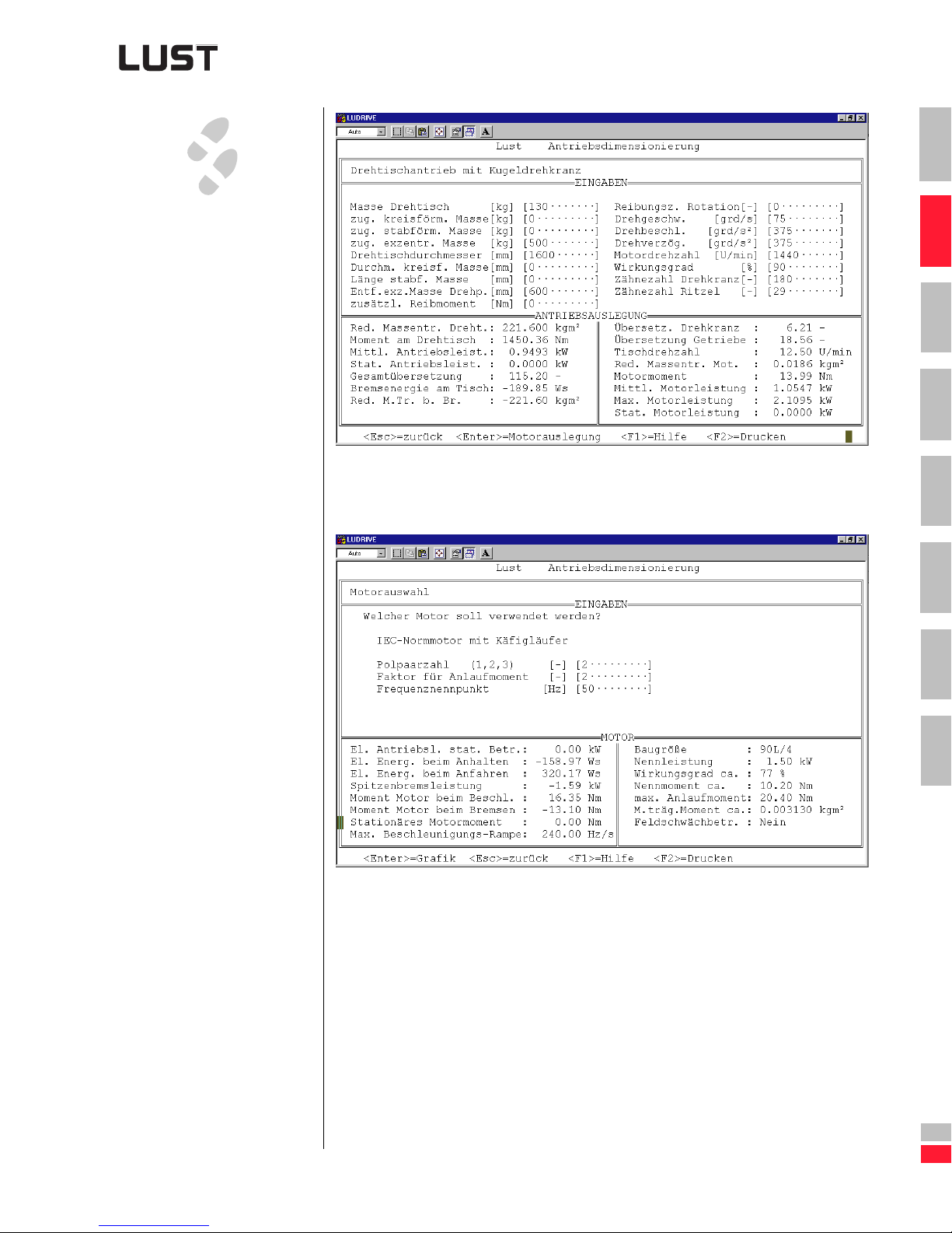
Figure 2.13 Calculation
3.
100% motor overload
with “SFC”
Factor for starti ng
torque = 2 (2
.
MN)
2 Drive definition
1
2
3
4
5
6
7
A
Figure 2.14 Motor selection
Engineering Guide CDA3000
DE
EN
2-23
Page 57
2 Drive definition
A
n
s
f60⋅
P
-----------=
2.5 Selection of
motor
wide variety of three-p hase AC motors can be r un on the CDA3000
inverter system. Three-phase AC motors are manufactured in synchronous and asynchro nous design versions. The stator winding is des igned such that, when in se rvice in a three-phase AC system, a rotating
field is created in the motor which dr ives the rotor. The rotation speed is
determined by the following variables:
ns = synchronous speed
P = number of pole pairs
f = stator frequency
The motor type is determined by the rotor introduced into the rotating
field.
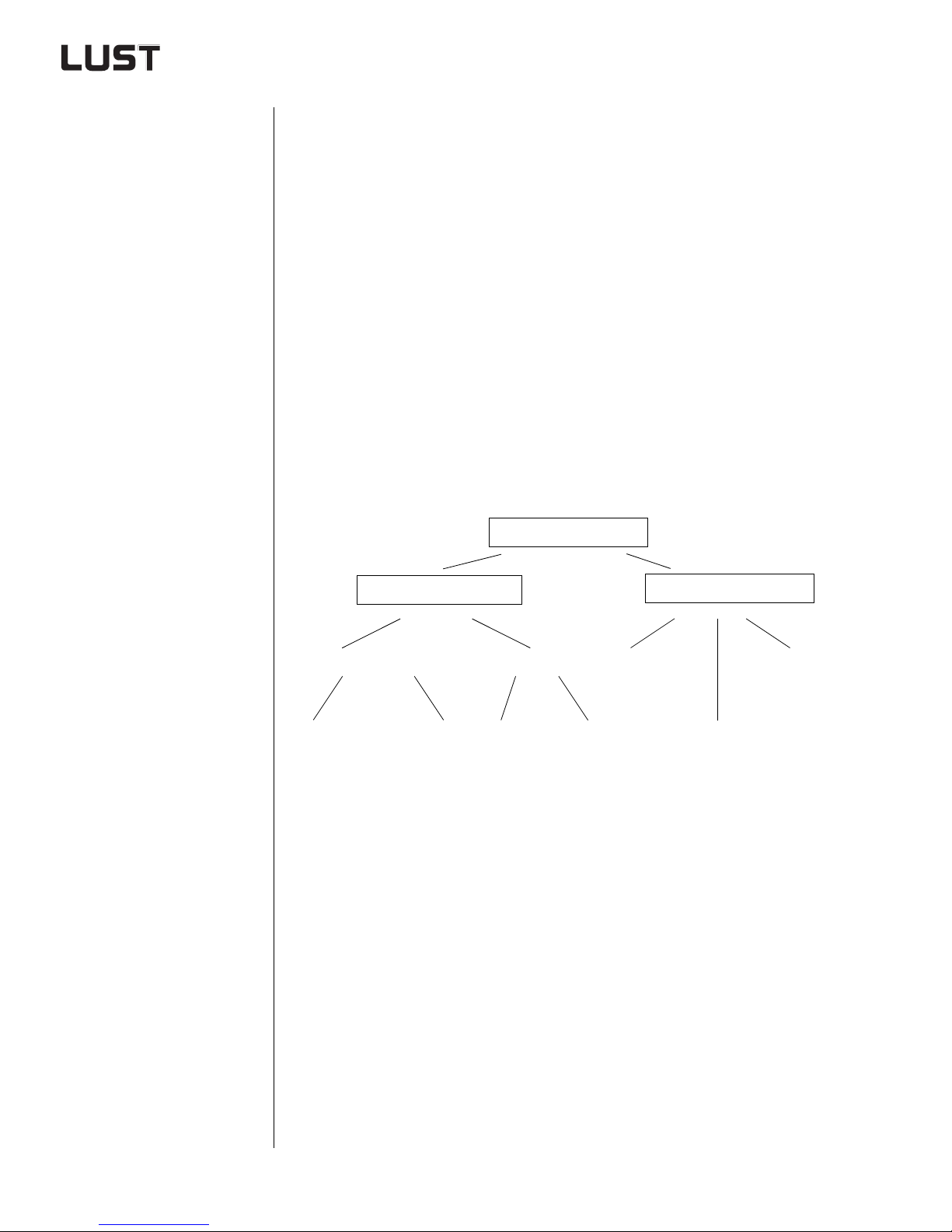
Overview of three-phase AC motors
3-phase AC motor
Synchronous motor
with energized rotor
Energized via
slip ring
Permanently
energized
(brushless)
Reluctance motor
With damper
cage
W ithout damper
cage
(SYNCELL)
Asynchronous motor
Standard motor Servomotor
HF motors
Engineering Guide CDA3000
2-24
Page 58
2 Drive definition
Typical areas of application of three-phase AC motors
Motor type
Standard three-phase
AC motor
Synchronous motor synchronous
Reluctance motor
High-frequency motor asynchronous
Asynchronous
servomot or
Working
principle
asynchronous
asynchronous/
synchronous
asynchronous
Application
In all industrial sectors. Around 10-15% of all
motors are speed-adjustable by way of inverters.
In the textile industry for: Spoolers, viscose
pumps, galette drives, roller drives etc.
Further areas of application are in the glass
and paper industry as winding drives, etc.
In the textile industry for: Spoolers, viscose
pumps, galette or roller motors, etc.
Further areas of application are in drafting
equipment and for synchronous running of two
axles.
In the timber processing industry as the main
drive. Further areas of application are grinding
and milling spindles, centrifuges, vacuum
pumps and winders.
In the packaging and food industries as a clock
and positioning drive. Further applications as
the main drive for machine tools.
1
2
3
4
5
6
Displacement-type
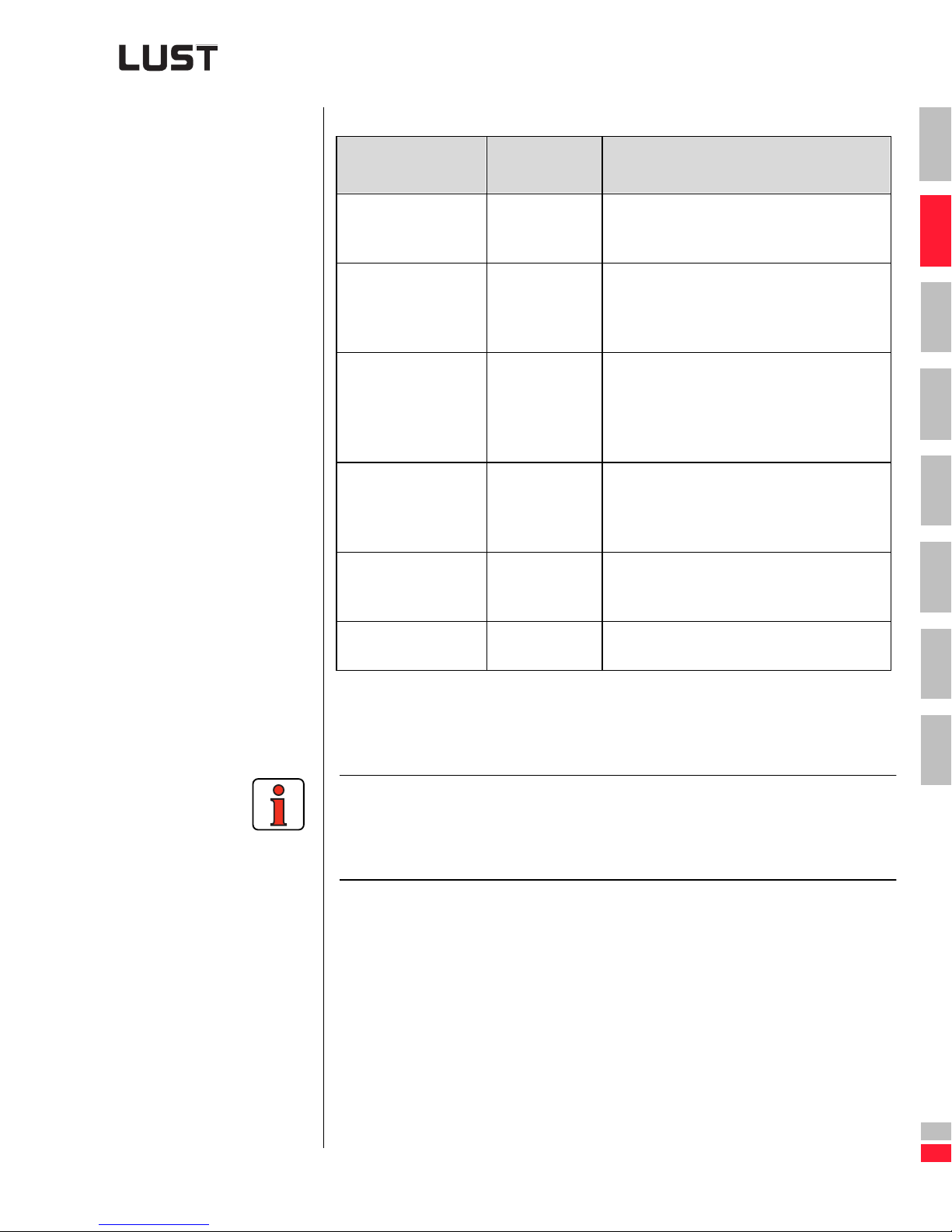
armature motor
Table 2.2 Areas of application for three-phas e AC motors
Use of the following sections
The following sections 2.5.1 to 2.5.5 summarize the typical characteristic
values. They provide an over view of the performance capabilities of th e
various motor types. Selection of the motors, dependent on application, is
presented in sections 3.3 to 3.6.
asynchronous
with motor brake
In conveyor sy stems as a traction and liftin g
motor.
7
A
Engineering Guide CDA3000
DE
EN
2-25
Page 59
2 Drive definition
2.5.1 Characteristic
values of standard threephase AC motors
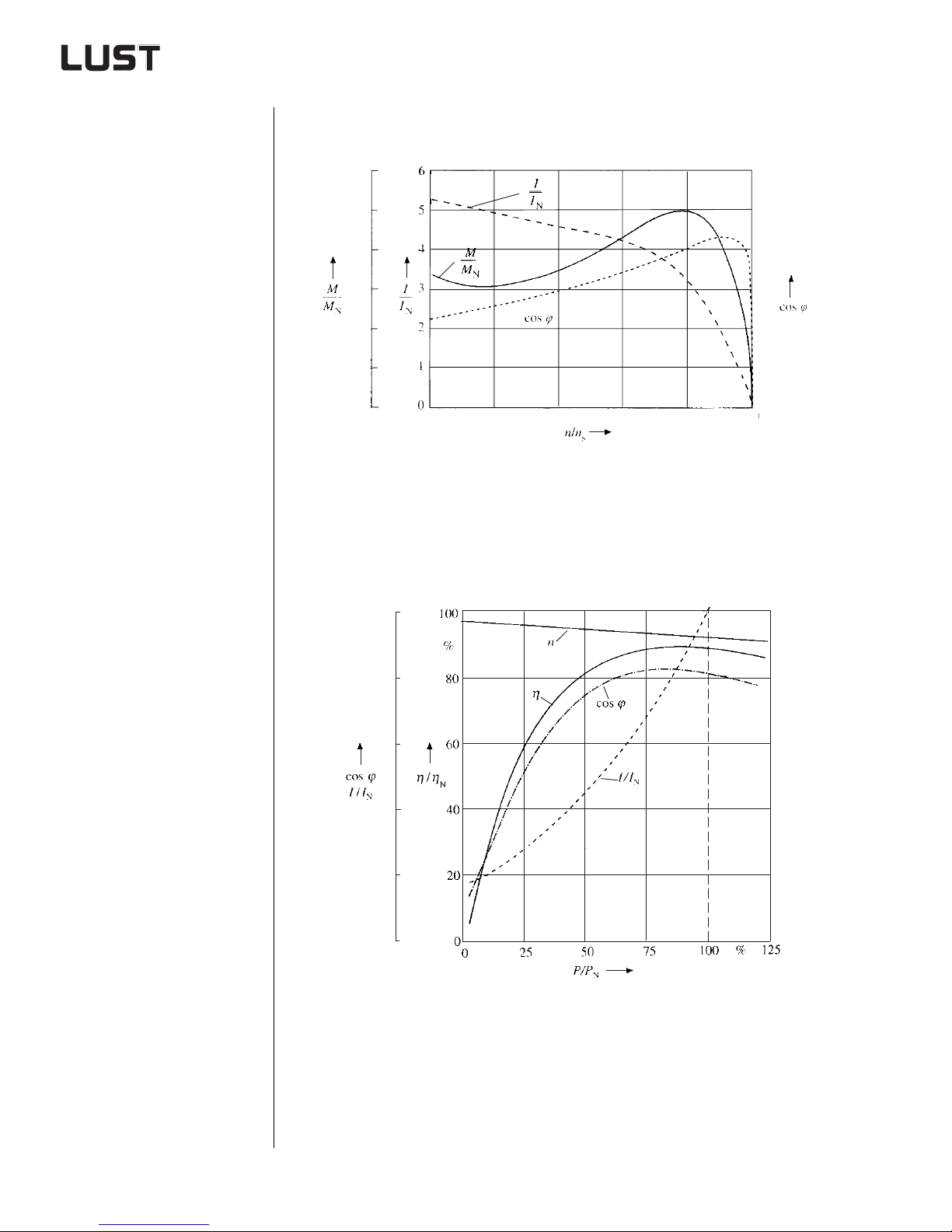
Startup characteristic in mains operation
2.4
2.0
1.6
1.2
0.8
0.4
0
0 0.2 0.4 0.6 0.8 1.0
1.0
0.8
0.6
0.4
0.2
0
Figure 2.15 Typical startup characteristic of a standard three-phase AC
motor in mains operation
Operating characteristic
1.0
0.8
0.6
0.4
0.2
0
Figure 2.16 Typical operating chara cteristic of a standard three-phase AC
motor
Engineering Guide CDA3000
2-26
Page 60
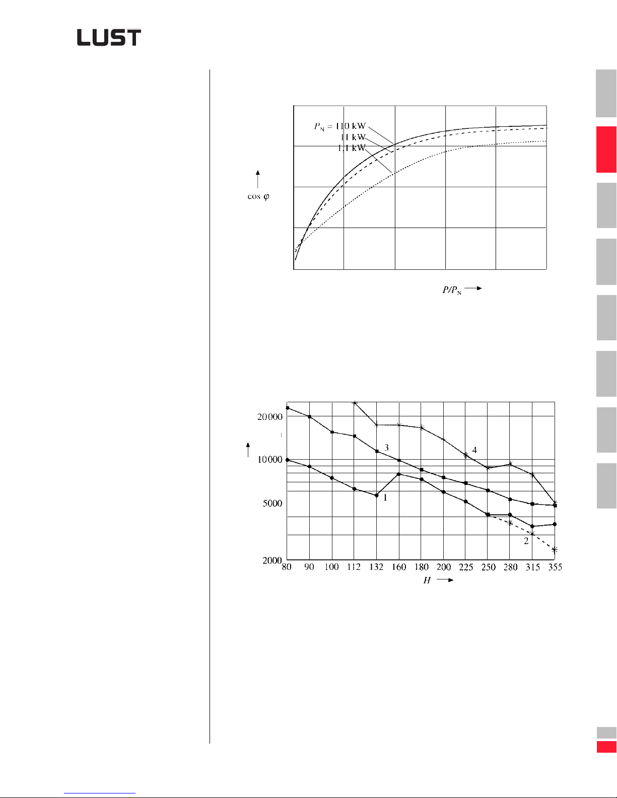
Power factor
2 Drive definition
1.00
0.75
0.50
0.25
0
0 0.25 0.50 0.75 1,00 1.25
P/PN Loading on the shaft
Figure 2.17 Power factor cos ϕ of a four-pole standard three-phase AC
motor
Limit speed
1500 rpm
1
2
3
4
5
6
rpm
max
n
n
Limit speed
max
H Axle height
1 Greased groove ball bearings in two-pole motors
2 Greased groove ball bearings in four-pole motors and higher
3 Strength of the short-circuiting rings of the rotor cage
4 Bend-critical speed
Figure 2.18 Typical limit speed of a standard three-phase AC motor
7
A
Engineering Guide CDA3000
DE
EN
2-27
Page 61
2 Drive definition
For more information on rotating electric machin es, rating and operating
behavior, refer to standard DIN VDE 0530 or
EN 60034-1.
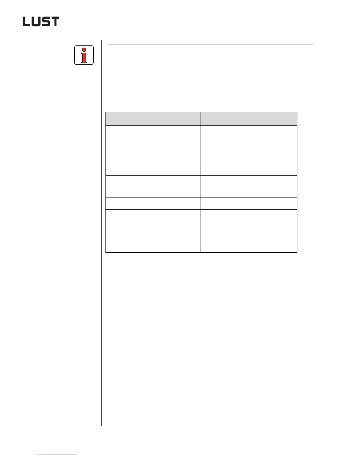
T olerances of standard three-phase A C motor to DIN 57 530/IEC 34
Property Tolerance
≤ 50 kW - 0.15 (1- η)
P
Efficien cy [ η ]
Power factor [ ϕ ]
Slip [ s ] ± 20%
N
> 50 kW - 0.1 (1- η)
P
N
1 ϕcos–
-------------------- -–
6
min. 0.02; max. 0.07
Break-away starting current [ l
Break-away torque [ M
Breakdown torque [ M
Noise [ L
]
A
]
A
]
K
Voltage deviation [ u ]
]
A
+ 20%
-15% to +20%
+3 dB(A)
±5% at rated load and 45ºC ambient temperature
Table 2.3 Tolerances to DIN 57530 and IEC 34
-10%
Engineering Guide CDA3000
2-28
Page 62
Notes:
2 Drive definition
1
2
3
4
5
6
7
A
Engineering Guide CDA3000
DE
EN
2-29
Page 63
2 Drive definition
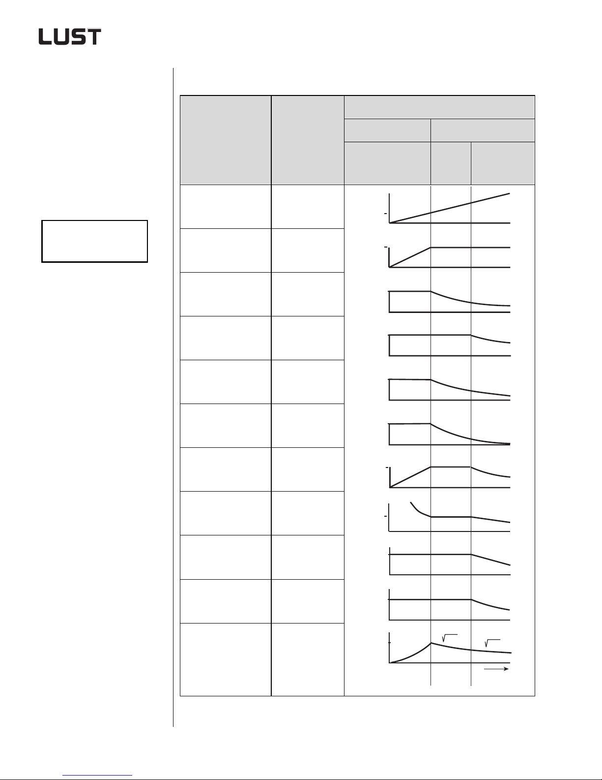
Limit frequency in inverter operation
Dependencies of the motor variables in inverter operation
Characteristic of referenced variable
fGf
N
M
------ -
M
Variable
Speed [n]
K
07,⋅⋅≈
N
Voltage [U]
Flux [
]
Φ
Current [I]
Torque [M]
Breakdown torque
]
[M
k
Mechanical
output [P
]
2
Referenced
variable
n
-----
n
N
U
-----
U
N
Φ
------ -
Φ
N
I
--- -
I
N
M
------ -
M
N
M
k
---------
M
kN
P
2
-----
P
N
Constant flux Field weakening
M=const.
1
0
1
0
1
0
1
0
1
0
1
0
1
0
f/f
N
f/f
N
1
1
1
1
f/f
N
P2=
const.
f/f
N
1
f
/f
N
1
fN/f
/f) ²
(f
N
1
P
∼
2
f/f
N
1
/f
f
N
/f
f
G
/f) ²
(f
G
/f) ²
(f
N
fG/f
1
--
n
copper loss [P
copper loss [P
Core loss [P
Table 2.4 Dependencies of the motor variables
Engineering Guide CDA3000
Slip [s]
Stator
Rotor
Fe
cu1
cu2
s
---- -
s
N
P
cu1
]
]
]
------------ -
P
cu1N
P
cu2
------------ -
P
cu2N
P
Fe
----------
P
FeN
1
f
/f
N
0
1
1
0
1
1
0
1
0
3/2
(f/fN)
0
1
1
1
fN/f
f
N
fG/f
/f) ²
(f
G
(fG/f) ²
/f
f
N
f
f
G
2-30
Page 64
2 Drive definition
Abbrevia tio ns use d in Table 2.4
f Frequency
f
N
f
G
I Current, effective value
I
N
M Torque
M
M
M
n Speed
n
N
P
P
P
P
P
P
P
s Slip
U Voltage, ef fective value
Φ Magnetic flux
Rated frequency
Limit frequency in invert er operation
Rated current
Breakdown torque
k
Nominal breakdown torque
kN
Nominal torque
N
Nominal speed
Stator copper loss
cu1
Rotor copper loss
cu2
Nominal stator copper loss of fundamental
cu1, N
Nominal rotor copper loss of funda mental
cu2, N
Core loss
Fe
Rated power
N
Mechanical output
2
1
2
3
4
5
6
Achtung: Safe inve rter operation can only be guaranteed when the
max. output frequency is not higher than the limit frequency
(f6).
7
A
Engineering Guide CDA3000
DE
EN
2-31
Page 65
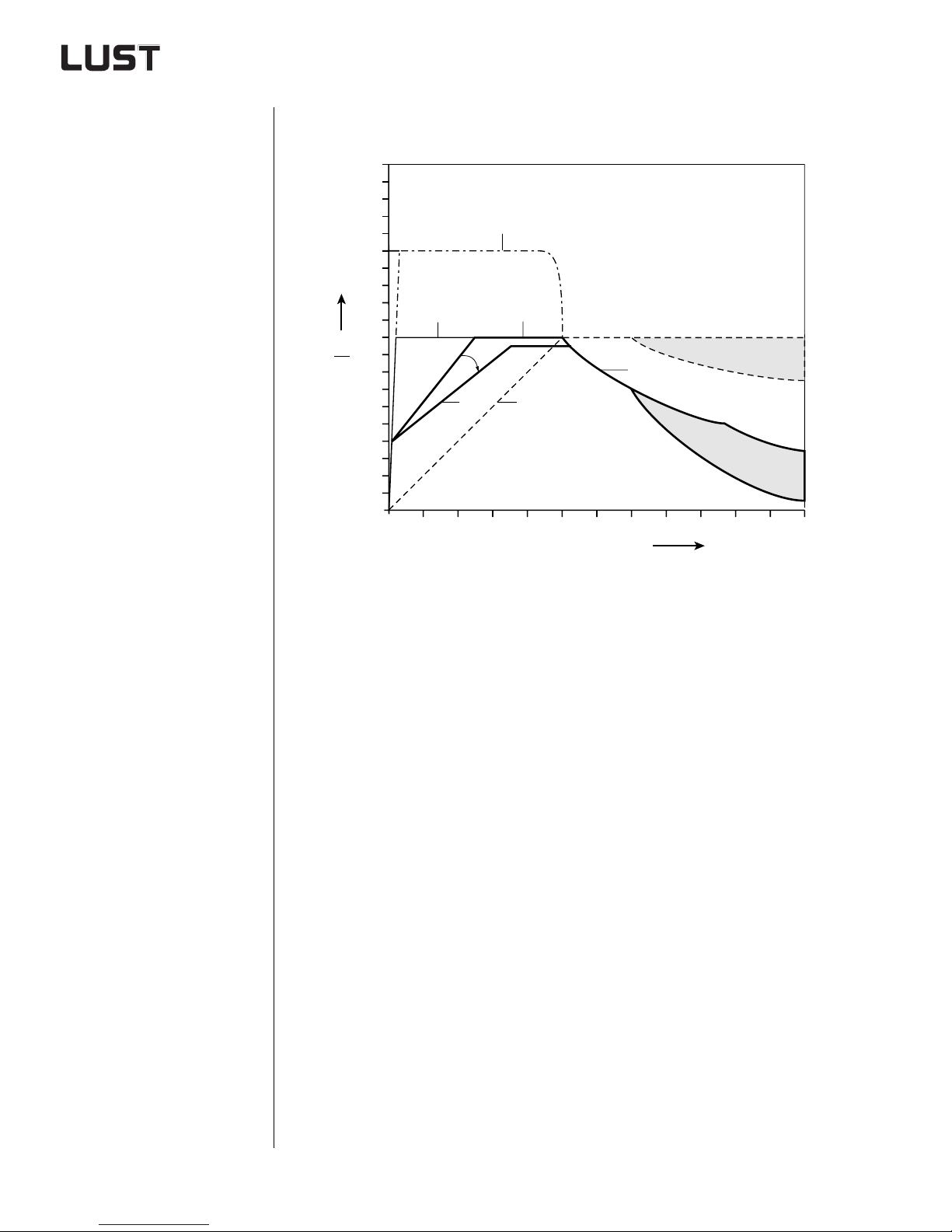
2 Drive definition
T ypical torque characteristic of a standar d three-phase AC motor
in standard inverter operation
2.0
(4)
1.5
M
M
(3)
1.0
N
(2)
0.5
0.1
P >
(2)
(1)
(2)
1005010
120
f [ Hz]
(1) Delivered power output of a 3-phase AC motor with inverter
(2) Permissible torque characteristic of an internally cooled 3-phase AC
motor
(3) Permissible torque characteristic of an adequately externally cooled
3-phase AC motor
(4) Maximum permissible torque for 120 s to DIN VDE 0530 Part 1
Figure 2.19 Torque characteristic of a standard three-phase AC motor in
inverter operation
Engineering Guide CDA3000
2-32
Page 66
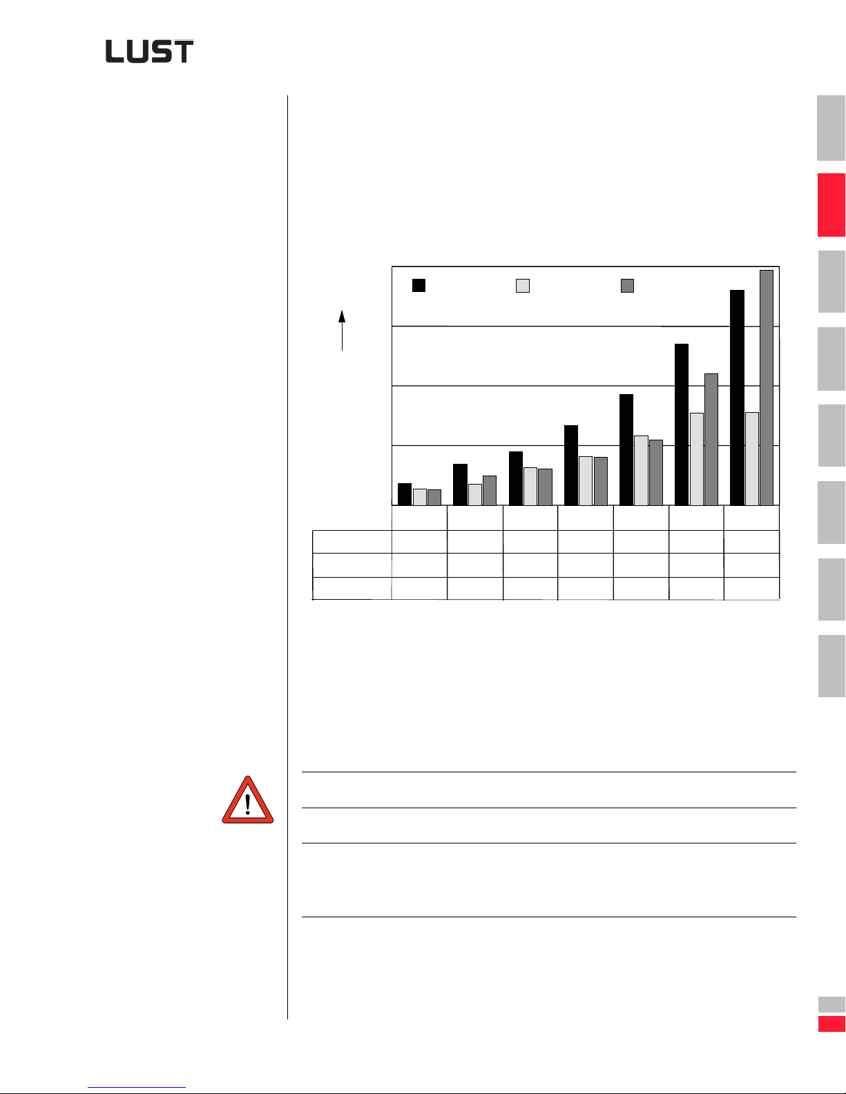
2 Drive definition
Acceleration from
0 rpm to nominal
speed in 100 ms
Typical acceleration behavior of standard three-phase AC
motors
JM Moment of inertia of the motor (rotor) in [kgm²]
tBE Acceleration time in [s]
PMBE Motor acceleration time in [W]
(1)
(2)
(3)
P
MBE
JMn2⋅
----------------------=
91 2, tBE⋅
2000
W
1500
1
2
3
MBE
1000
P
500
0
250 W
(1)
(2)
(3)
(1) 1 pole pair
(2) 2 pole pairs
(3) 3 pole pairs
Figure 2.20 Acceleration behavior as a function of of number of pole pairs of
186
138
132
standard three-phase AC moto r
370 W
345
180
248
550 W
449
316
307
750 W
669
407
406
1.1 kW
928
580
548
1.5 kW
1350
772
1100
2.2 kW
1800
780
1970
4
5
6
7
A
Engineering Guide CDA3000
Motors with one pole pair are unsuitable for dynamic drive tasks.
In summary: As the di agram shows, standard three-phase AC
motors with two pole pairs (four-pole) are particularly
well suited to dynamic drive tasks.
DE
EN
2-33
Page 67
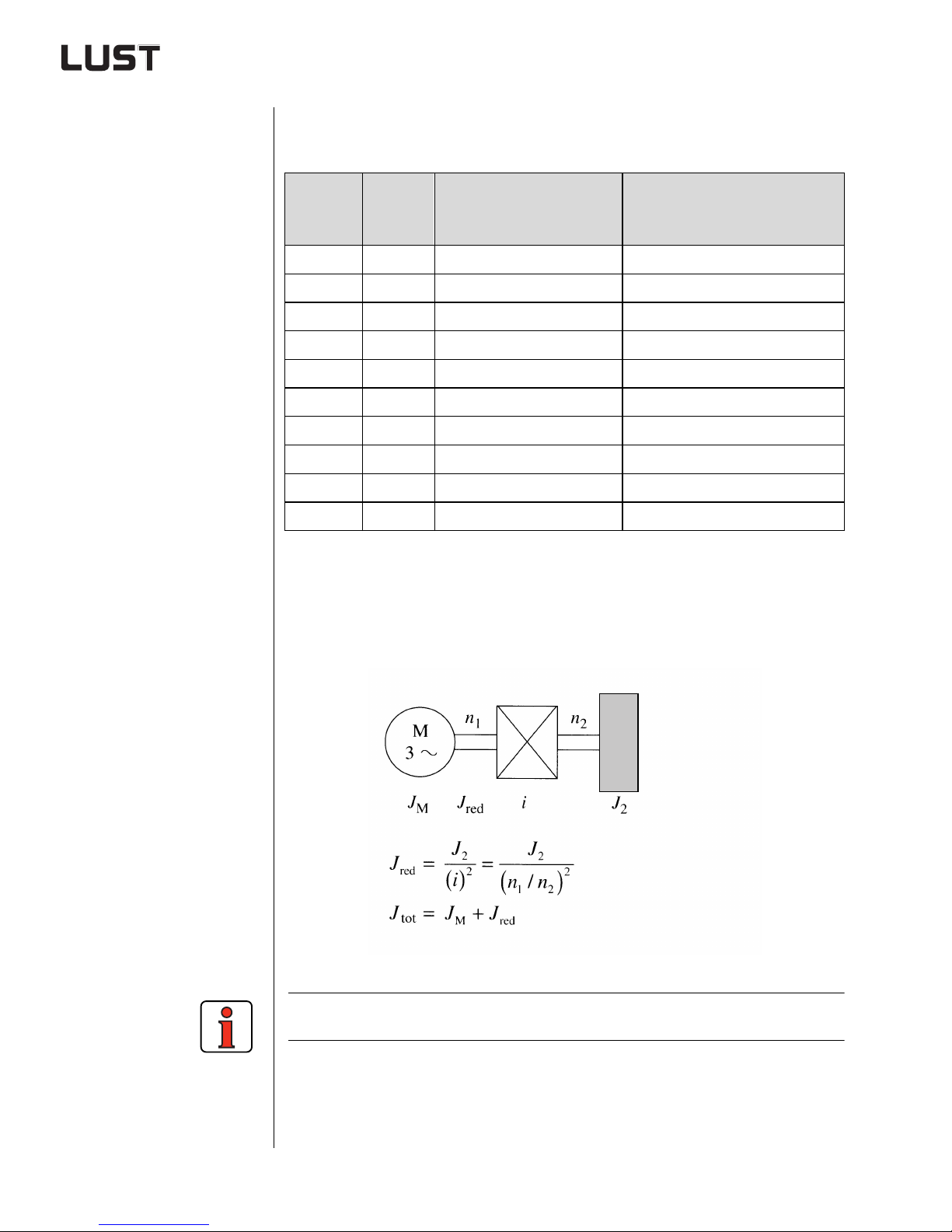
2 Drive definition
Typical max. acceleration times of four-pole standard threephase AC motors
Acceleration time with moment
of inertia adaptation in ms
=IM]
[I
red
Size
Power
P in W
Idle acceleration time in
red
=0]
ms [I
63L/4 250 55 110
71L/4 375 49 98
80/S/4 550 57 114
80L/4 750 54 108
90S/4 1100 52 104
90L/4 1500 52 104
90L/4a 2200 35 70
100L/4 2200 50 100
100L/4a 3000 50 100
112M/4 4000 123 246
Table 2.5 Max. acceleration times of four-pole standard three-phase AC
motors
Example: Equations for reduction via a gearbox
For further calculations of mass moments of inertia See Appendix A.2 .8.
Engineering Guide CDA3000
2-34
Page 68
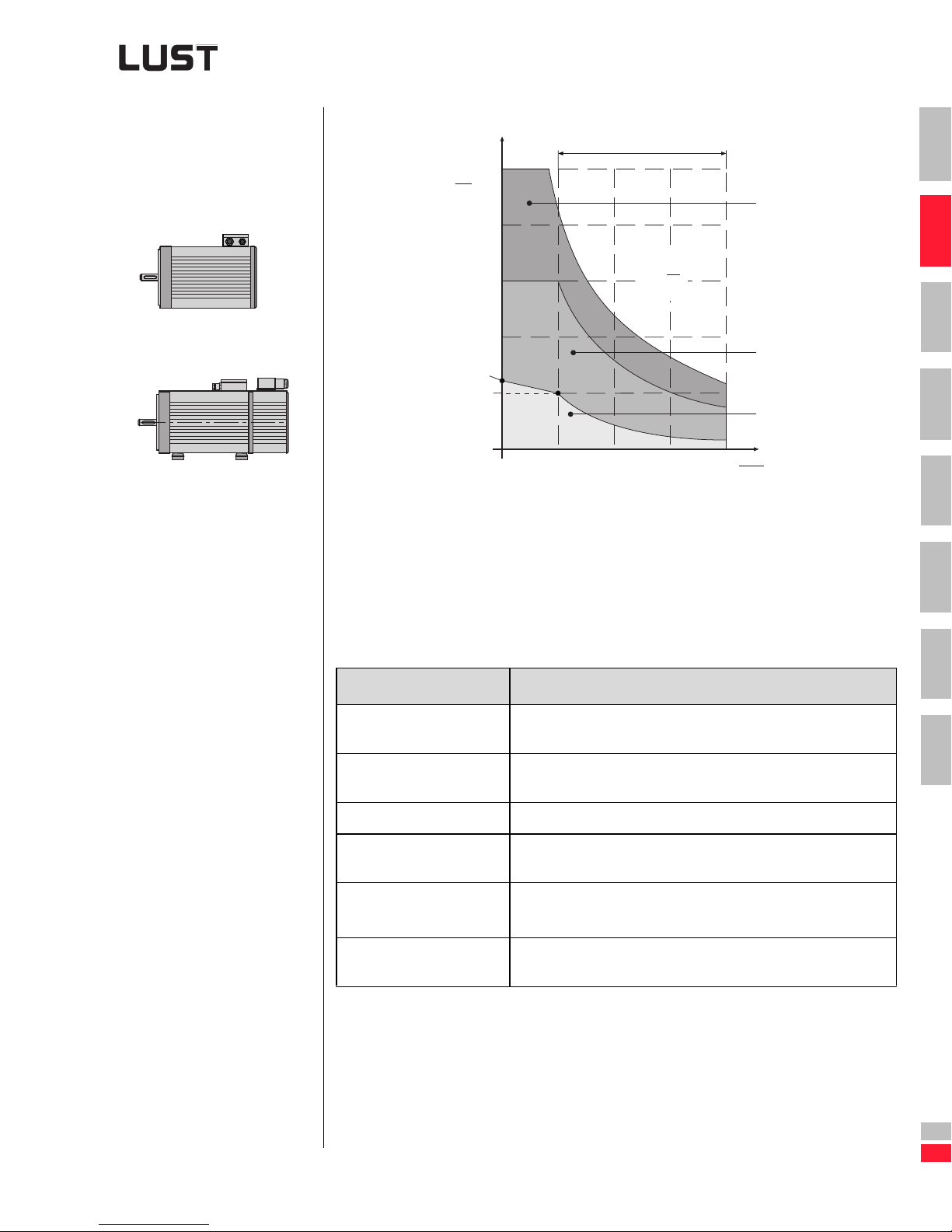
2.5.2 Characteristic
values of asynchronous servomotors ASx
2 Drive definition
M
max
5
M
M
N
4
(A)
1
(1)
2
1
3
M~
n
Without incremental
encoder
With incremental
encoder
2
M
0
M
N
1
n
N
2
3
(2)
(3)
n
4
n
N
(1) Pulse mode (2) Intermittent (3) Continuous
Figure 2.21 M-n characteristic for asynchronous motors
Abbreviations used
Term Explanation
Standstill torque Thermal limit torque of the motor at standstill. The motor can
M
0
deliver this torque for an unlimited length of time.
Standstill current Effective value of the motor phase current required to generate
I
0
the standstill torque.
3
4
5
6
7
A
Engineering Guide CDA3000
Nominal torque Thermal limit torque of the motor at nominal speed nN.
M
N
Rated current Effective value of the motor phase current required to generate
I
N
the nominal torque.
Rated power Full-load power of the motor at the nominal working point (MN,
P
N
) at rated current IN and rated voltage UN.
n
N
, I
M
max
Limit curve A maximum of five times the rated curr ent may be applied to
max
the motors.
2-35
DE
EN
Page 69
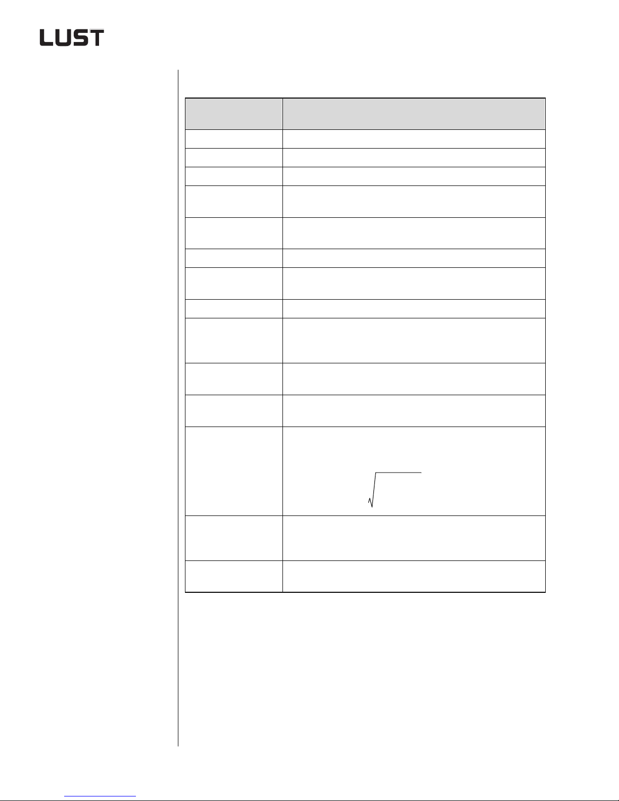
2 Drive definition
Standards and regulations
Property
Machine type Asynchronous servomotor
Design (DIN 42948) IM B35, IM B5, BV1, V3
Protection (DIN 40050) IP65, shaft seal IP64 (option IP65)
Insulating material
class
Cooling
Coating RAL 9005 (black)
Shaft end on the A (D)
side
Flange dimension DIN 42948 and IEC 72
Smooth running,
coaxiality and concen-
tricity to DIN 42955
Vibration severity to ISO
2373
Insulating material class F to VDE0530 winding overtemperature
and featherkey way DIN 6885, tolerance band k6
Asynchronous servomotors
ASx
= 105, coolant temperature tu=+40°C
∆τ
Self cooling (IC 0041) IP65
forced cooling (IC 0641) IP44,54
Cylindrica l shaft end DIN 748, featherkey
Tolerance N (normal)
R (reduced) on request
Stage N, optionally R
Therm. motor
monitoring
Torque load
Maximum pulse torque
Bearing servic e life
To prevent thermal overloading of the motors, the effective
load torque must not be greater than the nominal torque of the
Typically 2 to 5 times nominal torque, depending on controller
3 to 5 times nominal torque is permissible for max. 0.2 s.
The average service life under nominal conditions
PTC thermistor in stator winding
M
eff
Table 2.6 General technical data
servomotor.
2
ΣM
---------------------- -=
(Mmax. ≤ MN) is 20,000 h.
tn×
n
assignment.
M
eff
MN≤
Engineering Guide CDA3000
2-36
Page 70
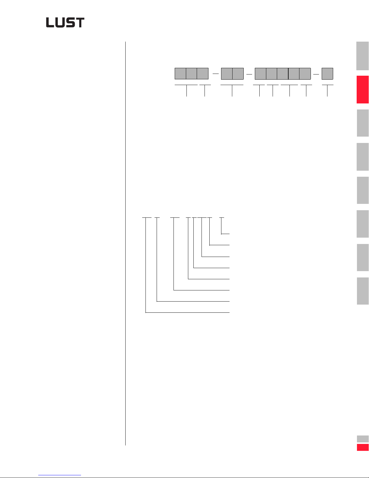
2 Drive definition
A
Type code for asynchronous servomotor ASX
1
B
or
type
g
S
=
Async
A
vomot
r
Se
s
n, coolin
nou
o
hr
g
Desi
ASM - 23 - 20003 - 0
C
h
gt
en
l
,
ize
S
Vol
D
t
an
i
brake
r
a
ng
Holdi
ncoder sy
E
The order designation
must always be quoted
in full in the
specified order.
ta
ge v
F
E
tem
s
Nominal
sp
Termin
G
eed
a
tion
technique
H
2
3
4
5
No encoder connection
Nominal speed 3000 rpm
Without encoder
Without holdi ng br ak e
6
7
Voltage variant 330V
Size 2, length 3
Flange, self cooling
Asynchronous servomotor
Engineering Guide CDA3000
2-37
A
DE
EN
Page 71
2 Drive definition
Technical data of the asynchronous servomotors with self cooling
Self cooling
M
0
[Nm]
MN
[Nm]PN[kW]
I
[A]
I
0
[A]
nN
N
[rpm]JL[kgcm²]m[kg]
nmax
[rpm]
ASM (H)-11 -2xxx3 1.5 1.3 0.41 1.6 1.4 3000 2.8 6.5 12000
ASM (H)-12 -2xxx3 2 1.7 0.54 2.1 1.8 3000 3.7 7.5 12000
ASM (H)-13 -2xxx3 2.7 2.3 0.72 2.74 2.3 3000 4.7 8.5 12000
ASM (H)-14 -2xxx3 4.2 3.5 1.1 4 3.3 3000 6.5 10.2 12000
ASM (H)-15 -2xxx3 5.2 4.7 1.5 5.4 4.5 3000 8.9 12.8 12000
ASM (H)-21 -2xxx3 4.2 3.5 1.1 3.6 3 3000 10.9 10.8 12000
ASM (H)-22 -2xxx3 5.6 4.7 1.5 4.7 3.9 3000 14.4 13.2 12000
ASM (H)-23 -2xxx3 8.4 7 2.2 6.7 5.6 3000 21.5 16.2 10000
ASM (H)-24 -2xxx2 12 10 2.1 6.4 5.3 2000 29.8 20.3 10000
ASM (H)-25 -2xxx2 15 13 2.7 7.7 6.6 2000 38.4 24 8000
ASM (H)-31 -2xxx1 15.5 13 2.1 6.2 5.2 1500 70 29.8 8000
ASM (H)-32 -2xxx1 20 17 2.7 8.2 6.8 1500 90 33 8000
ASM (H)-33 -2xxx1 27.5 23 3.6 10.3 8.7 1500 130 41.5 8000
ASM (H)-34 -2xxx1 42 35 5.5 15.1 12.6 1500 209 56.6 8000
ASH-41-2xxx1 47 40 6.3 21 17.9 1500 450 87 8000
ASH-42-2xxx1 70 60 9.4 30 25.5 1500 740 113 8000
ASH-43-2xxx1 85 70 11 37 30.4 1500 960 135 8000
Table 2.7 Technical data, self cooling
Abbreviations used
Term Explanation
Standstill torque Thermal limit torque of the motor at standstill. The motor can
M
0
deliver this torque for an unlimited length of time.
Standstill current Effective value of the motor phase current required to generate
I
0
the standstill torque.
Nominal torque Thermal limit torque of the motor at nominal speednN.
M
N
Rated current Effective value of the motor phase curr ent required to gene rate
I
N
the nominal torque.
Rated power Full-load power of the motor at the nominal working point
P
N
, nN) at rated current IN and rated voltage UN.
(M
N
, I
M
max
Limit curve A maximum of five times the rated current may be applied to
max
the motors.
Engineering Guide CDA3000
2-38
Page 72
2 Drive definition
Technical data of the asynchronous servomotors with forced
cooling
Forced cooling
M
0
[Nm]
MN
[Nm]PN[kW]
I
[A]
I
0
[A]
nN
N
[rpm]JL[kgcm²]m[kg]
nmax
[rpm]
1
ASF (V)-11 -2xxx3 2 1.7 0.54 2.1 1.8 3000 2.8 7.5 12000
ASF (V)-12 -2xxx3 2.7 2.3 0.72 2.8 2.4 3000 3.7 8.6 12000
ASF (V)-13 -2xxx3 3.6 3 0.94 3.54 2.9 3000 4.7 9.7 12000
ASF (V)-14 -2xxx3 5.6 4.7 1.5 5.1 4.3 3000 6.5 12.5 12000
ASF (V)-15 -2xxx3 7.7 6.5 2 7.3 6.2 3000 8.9 14,2 12000
ASF (V)-21 -2xxx3 5.6 4.7 1.5 4.6 3.9 3000 10.9 13.8 12000
ASF (V)-22 -2xxx3 8.4 6.5 2 6.5 5 3000 14.4 16.2 12000
ASF (V)-23 -2xxx3 12 10 3.1 8.9 7.4 3000 21.5 19,2 10000
ASF (V)-24 -2xxx2 15.5 13 2.7 8 6.7 2000 29.8 23.3 10000
ASF (V)-25 -2xxx2 19.7 16.5 3.4 9.8 8.2 2000 38.4 27 8000
ASF (V)-31 -2xxx1 21.5 18 2.8 8.4 7 1500 70 33.8 8000
ASF (V)-32 -2xxx1 27.5 23 3.6 10.6 8.9 1500 90 37.5 8000
ASF (V)-33 -2xxx1 38 32 5 13.8 11.6 1500 130 46.5 8000
ASF (V)-34 -2xxx1 56 47 7.4 18.4 15.4 1500 209 62.1 8000
ASV-41-2xxx1 83 70 11 33 27.5 1500 450 95 8000
ASV-42-2xx1 140 118 18.5 50 42 1500 740 121 8000
ASV-43-2xxx1 170 143 22.5 61 51 1500 960 145 8000
2
3
4
5
6
7
Engineering Guide CDA3000
Table 2.8 Technical data, forced cooling
Abbreviations used
Term Explanation
Standstill torque Thermal limit torque of the motor at standstill. The motor can
M
0
deliver this torque for an unlimited length of time.
Standstill current Effective value of the motor phase current required to generate
I
0
the standstill torque.
Nominal torque Thermal limit torque of the motor at nominal speed nN.
M
N
Rated current Effective value of the motor phase current required to generate
I
N
the nominal torque.
Rated power Full-load power of the motor at the nominal working point
P
N
, nN) at rated current IN and rated voltage UN.
(M
N
, I
M
max
Limit curve A maximum of five times the rated curr ent may be applied to
max
the motors.
2-39
A
DE
EN
Page 73
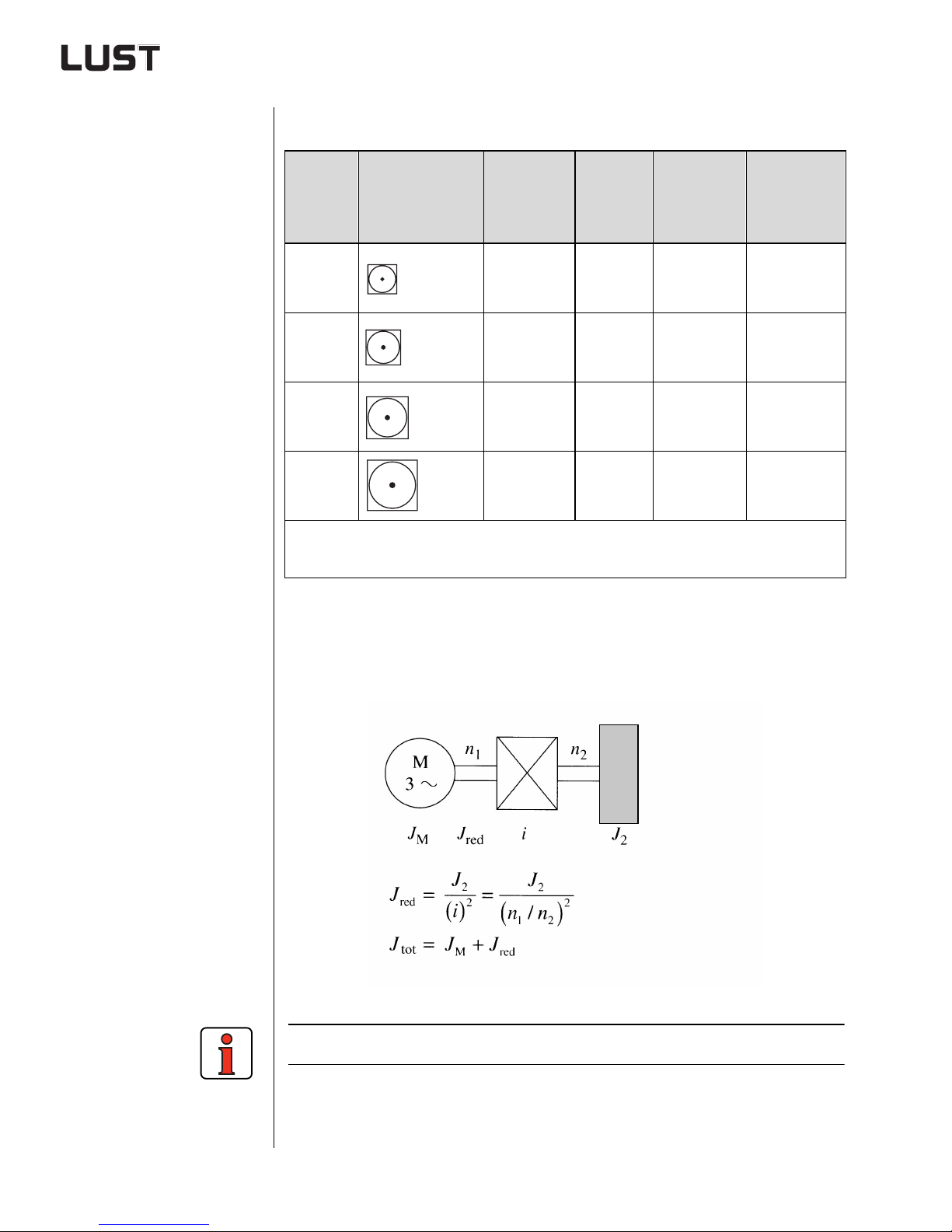
2 Drive definition
Typical max. acceleration times of asynchronous servomotors
ASx Size
Length
Installation
window [mm]
Accelera-
tion torque
[Nm]
Power
class [kW]
Idle accele-
ration time
[ms]
=0
I
red
Acceleration
time
[ms]
=IM
I
red
11 to 15 110x110 3,25 to 11.75 0.4 to 1.5 14 to 12 28 to 24
21 to 25 140x140 8.75 to 32.5 1.1 to 2.7 20 to 19 40 to 38
31 to 34 190x190 32.5 to 87.5 2.1 to 5.5 34 to 38 68 to 76
41 to 43 260x260 100 to 175 6.3 to 11 71 to 87 142 to 174
Precondition: Acceleration from 0 to 1500 rpm
at 2.5 times nominal torque and idle (I
red
=0)
Table 2.9 Idle accele ration time
Example: Equations for reduction via a gearbox
Calculation of mass moments of inertia - See section A.2.8.
Engineering Guide CDA3000
2-40
Page 74
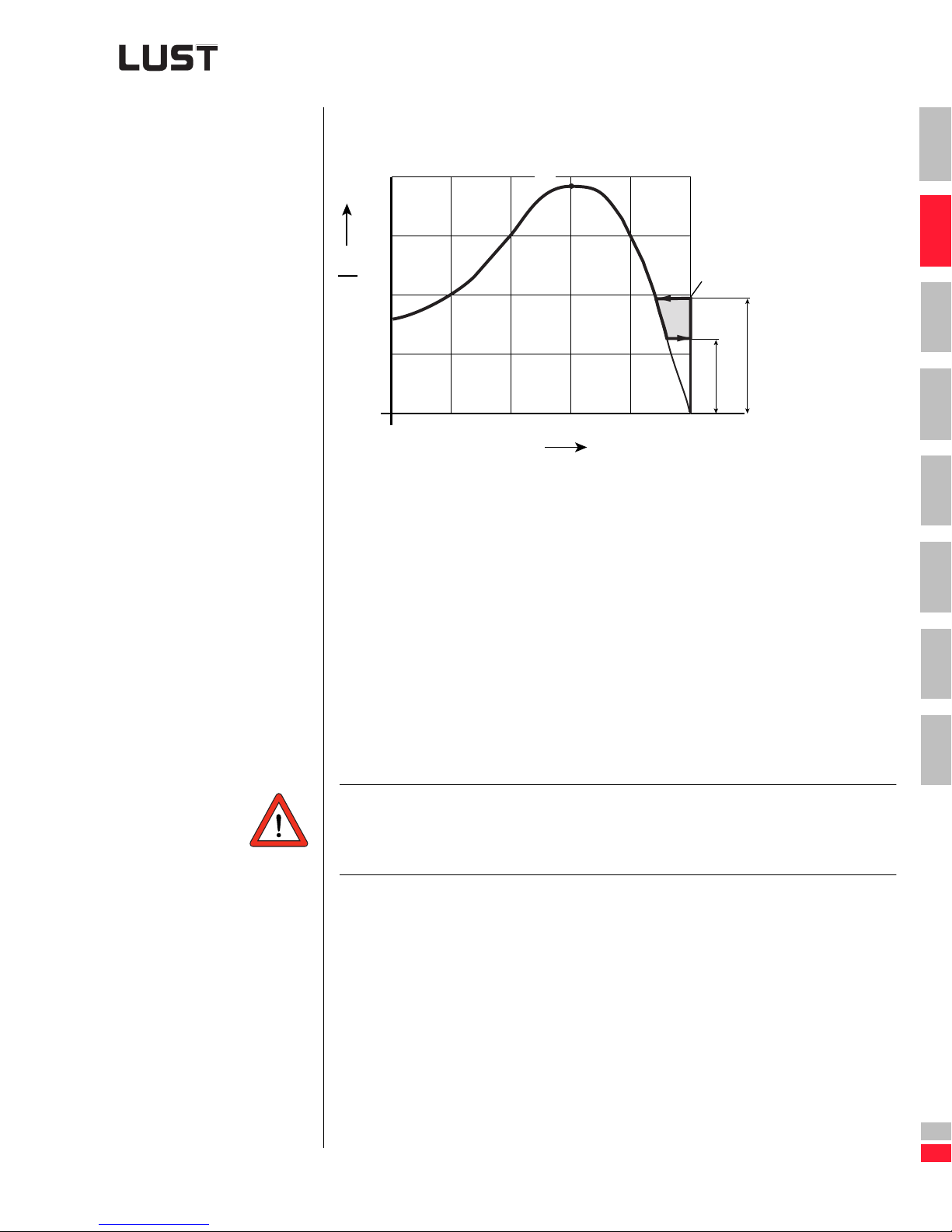
2 Drive definition
2.5.3 Characteristic
values of reluctance motors
Typical torque characteristic
M
0.4
n/n
K
0.6
N
M
sy
4
3
M
M
N
2
1
0.2
(1) Pull-in to synchronism
1
2
M
ksy
3
(2)
(1)
0.8
1
4
5
12, MN⋅≈
ksy
16bis18,, MN⋅≈
(2) Pull-out of synchronism
35, MN⋅≈
M
K
Figure 2.22 Typical torque characteristic of a reluctance motor in mains
operation
Note: The motor may only be run to accelerate in as ynchronous
mode. If asynchronous mode is r un for longer the motor will
be destroyed.
M
6
7
A
Engineering Guide CDA3000
DE
EN
2-41
Page 75
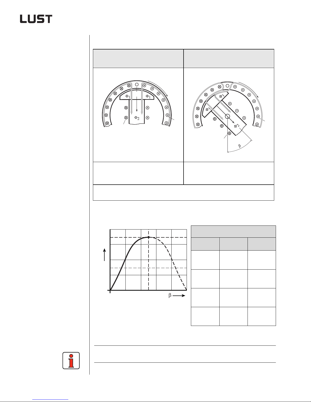
2 Drive definition
Torque as a function of load angle
Idling of the reluctance/
synchronous motor
N
X
S
I
I
2
1
The stator field Φ1 with the field sy stem of
the rotor Φ2 represents a fixed magnetic
adhesion.
X Direction of rotation
Load angle
β
Loading of the reluctance/
synchronous motor
N
S
I
2
X
I
1
As the load on the shaft increases, the rotor
displacement angle/load angle increases
steadily. The speed remains synchronous.
Table 2.10 Torque as a function of rotor displacement angle
(load angle)
M
ksg
referred to the motor shaft
β
Pole pairs
βMN typical β
1 20° 45°
M
N
2 10° 22.5°
90˚
3 6.75° 15°
4 5° 11,25°
Table 2.11 Internal torque as a function of load angle
Internal torque (Mi)
M
k Φ i βsin⋅⋅⋅=
i
β
Mksg
Engineering Guide CDA3000
2-42
Page 76
Project planning notes
2 Drive definition
A 3-phase AC reluctance motor is a special motor which must be tested
anew prior to every production deployment. Depending on the
situation, smooth running, heat, noise or vibration problems may occur.
The following table presents a listing of key points which may need to be
considered.
Detailed information can only be provided by the manufacturer of the
reluctance motor, however.
Subject Project planning notes
See manufacturer’s data sheet
Tips:
• Winding always in star configuration (high inductance)
Motor design
Inverter design
• Inquiries for motors for S3 to S6 operation must usually be
submitted separately
• Motor protection only possible via PTC or Klixon
• High tendency to vibrate, especially < 25Hz
In static operation
I
Motor
N
Motor
N
N
)
N
• I-Inverter ≈ 1,2 I
In dynamic operation
• I-Inverter
• Shut down the slip compensation, load compensation and V/F
character ist ic ad a p ta t ion so ft w ar e functions
• V/F characteristic with at least 3-6 fully programmable interpolation points
• At frequencies > 150 Hz an additional filter must very often be
inserted in the motor cable
• The max. output frequency must not be higher than F
(frequency nominal point).
• When motors are connected up a very high short-circuit current flows (typically up to 30-40 times I
≈ 1.8
1
2
3
4
5
6
7
A
Engineering Guide CDA3000
Table 2.12 Project planning notes for drive system with reluctance motors
DE
EN
2-43
Page 77
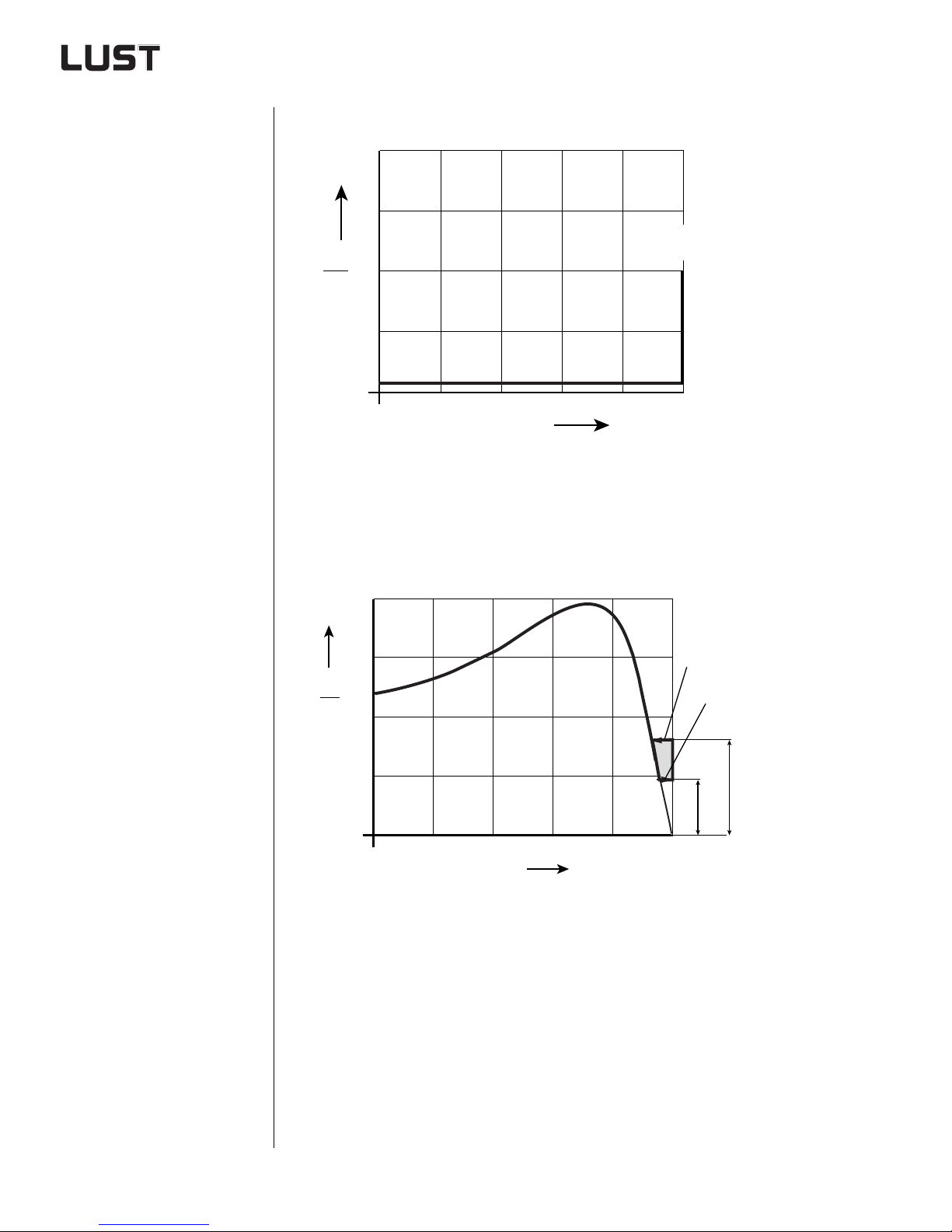
2 Drive definition
2.5.4 Characteristic
values of synchronous motors
Synchronous motor with salient-pole rotor
4
3
M
M
M
2
N
1
0.2
0.4
n/n
0.6
N
0.8
ksy
1
Figure 2.23 Typical torque characteristic of a synchronous motor with
salient-pole rotor
Synchronous motor with cage winding and permanent magnets
2.5
M
M
2
1.5
N
1
M
ksy
M
sy
(2)
(1)
0.2
Typical startup characteristic of a permanent magnet excited synchronous motor with cage wi nding for asynchronous self-running
(1) Pull-in to synchronism
(2) Pull-out of synchronism
M
M
0.4
n/n
sy
ksy
0.6
N
0.8
09, MN⋅≈
135, MN⋅≈
(corresponding to VD E 0530)
1
Figure 2.24 T y pical synchronous motor of a synchronous motor with cage
winding and pe rmanent magnets
Engineering Guide CDA3000
2-44
Page 78
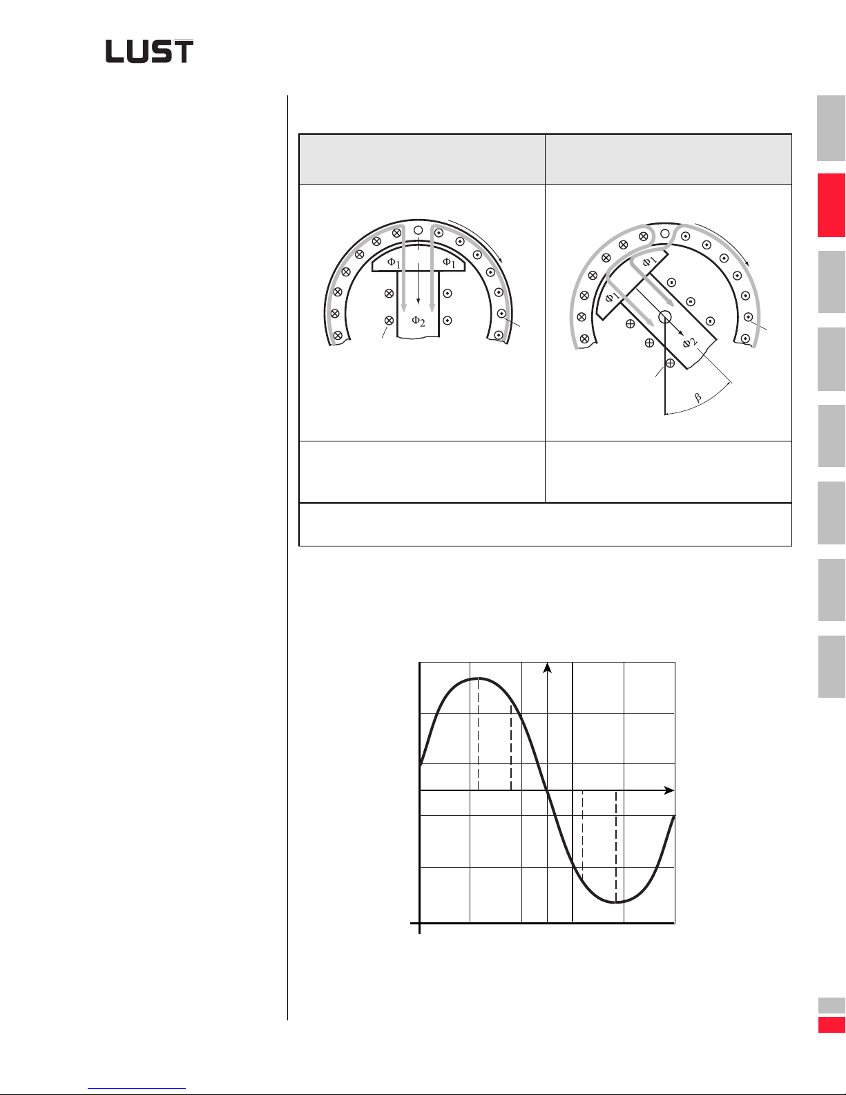
2 Drive definition
Torque as a function of load angle
Idling of the reluctance/
synchronous motor
N
X
S
I
I
2
The stator field Φ1 with the field system of
the rotor Φ2 represents a fixed magnetic
adhesion.
X Direction of rotation
Load angle
β
1
Loading of the reluctance/
synchronous motor
N
S
I
2
As the load on the shaft increases, the rotor
displacement angle/load angle increases
steadily. The speed remains synchronous.
X
I
1
1
2
3
4
5
6
Table 2.13 Torque as a function of rotor displacement angle
(load angle)
M
ksy
45˚
22.5˚
Generator
Figure 2.25 Torque as a function of load angle in the synchronous machine
with salient-pole r ot or
M
Motor
-22.5˚
M
ksy
-45˚
β
7
A
Engineering Guide CDA3000
DE
EN
2-45
Page 79
2 Drive definition
Project planning notes
A synchronous motor, too, is a special motor which must b e tested a new
prior to every production deployment. Depending on the situation, smooth
running, heat, noise or vibration problems may occur. The following table
presents a listing of key points which may need to be considered.
Subject Project planning notes
Motor design For precise data refer to the manufacturer’s data specification booklet
Tips:
• Synchronous motors with cage winding can be run on the mains
and on the inverter.
• The synchronous breakdown torque M
is approx. 1.35 x MN.
ksy
If a higher breakdown torque is required (e.g. 1.6 times), a higher-powered motor must be chosen.
• The external moment of inertia specified by the manufacturer
must not be exceeded, otherwise the motor will not be able to
generate the acceleration torque required for synchronization.
• At low frequencies the no-load current may be higher than the
load current.
• Motor protection only possible via PTC
• High tendency to vibrate
Inverter design In static operation with manipulating range <
• I-Inverter ~ I
Motor
N
In static operation with manipulating range <
• I-Inverter ~ 1.2 x I
Motor
N
1:5 (20-100 Hz)
1:5 (5-100 Hz)
With group drive
• Refer to the “Multi-motor operation” project planning notes,
section 3.3. The startup currents for connection of the motor to
max. frequency may be 30 ti mes the motor rated current.
• V/F characteristic with at least three pr ogrammable i nterpolat ion
points
• Shut down the slip compensation, load compensation and V/F
characteristic adaptation software functions
For rapid synchronization the motor should be run in the frequency
range to 50 Hz with current injection. In individual applications it will
be necessary to sto p t he acc eleratio n proc ess for 10 s at 5 Hz to allow
the motor time to switch to synchronous mode.
Table 2.14 Project planning notes for permanent magnet excited
synchronous motors with cage winding for asyn chr onous
self-starting.
Engineering Guide CDA3000
2-46
Page 80
2 Drive definition
Detailed information can only be provided by the manufacturer of the synchronous motor, however.
1
2.5.5 Characteristic
values of highfrequency
motors
Not available at time of going to press.
At frequencies > 1000 Hz special project planning directives must be
followed.
2
3
4
5
6
7
Engineering Guide CDA3000
A
DE
EN
2-47
Page 81
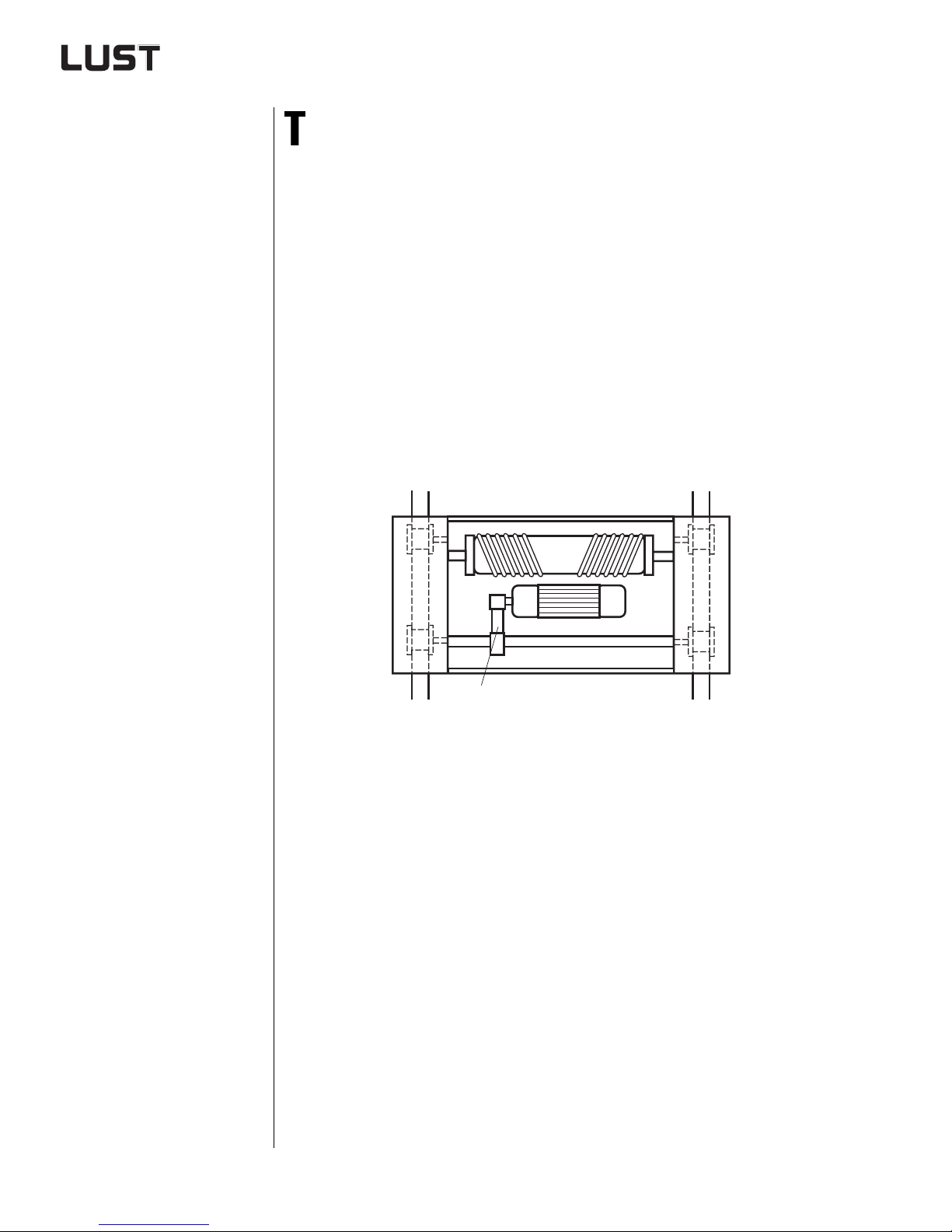
2 Drive definition
2.6 Selection of gearing
2.6.1 Transmission
gear
his section presents the key gearing data in table form. For precise
data regarding design, magne tic flux direction, transmission, play etc.
refer to the various manufacturers’ catalogues.
What points need to be considered in designing the gearing?
• Fitting location conditions (room conditions, temperature, position)
• Max. drive speed
• Max. output to rque
• Service factor (the standard gears are designed fo r uniform load)
• Transversal forces, axial forces
• Circumferential backlash
• Torsional rigid ity
Insertion of a transmission gear stage between the geared motor and the
output shaft result s in different gear output speeds and torq ues.
(1)
(1) Transmission gear with chain wheels
Figure 2.26 Transmission gear
Practical tip
➢ In practice the transmiss i on gear is usually implemented by way of
toothed belts
i
➢ i
max
= iv . i
tot
≈ 4, i
G
typical
= 2 to 3
iv Transmission gear reduction
Gear reduction
i
G
Engineering Guide CDA3000
2-48
Page 82
2 Drive definition
2.6.2 Characteristic
values of
standard gears
Characteristics
Magnetic flux straight straight rectangular rectangular
Max. torque [Nm]
2nd shaft end not possible possible possible possible
Hollow output shaft not possible possible possible possible
Reduction range
(without compound
transmission)
Efficiency 0.93 to 0.98 0.93 to 0.98 0.3 to 0.85 0.9 to 0.96
Circumferential back-
1)
lash in
Reduction mathema-
tically
(rating plate)
Cost DM/Nm low low medium relatively high
1)
2)
angle minutes
2)
precise?
For explanation See section 2.6.3
The cogs of the cogwheel pairing have common dividers so that different cogs always
engage with each other.
Example: i = Z2/Z1 = 96/16 = 5.9375 ⇒ Catalogue specification 5.94
Spur
gear
approx.
15,000
approx.
3.5 to 230
approx.
30 to 40
no no no no
Flat spur
gear
approx.
6,000
approx.
6 to 270
approx.
30 to 40
Worm
gear
approx.
4000
approx.
6 to 290
approx.
30 to 40
Bevel gear
approx.
40,000
approx.
6 to 165
approx.
25 to 40
1
2
3
4
5
6
2.6.3 Characteristic
values of
planetary gears
Table 2.15 Characteristic values of standard gears
Characteristics Standard gear P lanetary gear Bevel gear
Gear stages 1/2/3 1/2 1/2
Efficiency
(without worm gear)
Circumferential backlash
in angle minutes
Impulse torques poor ver y good poor
Torsional rigidity medium very good medium
Dynamics medium very good medium
Power density poor ver y good poor
Transmission math.
precise? (rating plate)
Cost DM/Nm low relatively high medium
very good very good very good
approx. 25 to 40 1 to 10 6 - 15
no yes yes
7
A
Engineering Guide CDA3000
Table 2.16 Characteristic values of planetary gears
2-49
DE
EN
Page 83

2 Drive definition
Circumferential backlash
The circumferential backlash of a gear is the angular tolerance b etween
the output and the drive, referred to the output shaft with the drive blocked
and a torque of approx. 3 to 5% of the nominal torque of the gear.
➢ Figures are always absolute values and in angle minute s.
➢ Figure is obtained with drive shaft stopped.
➢ Figure relates to the outp ut an d is obtained by means of an alterna-
ting load of approx. 3 to 5% M
Torsional rigidity
Torsional rigidity is the torsion of a gear relative to the loading.
max
.
➢ Figure always in Nm per angle minute.
➢ Figure is obtained with drive shaft stopped.
➢ Figure relates to the outp ut an d is obtained by means of an alterna-
ting load of approx. 0 to 100% M
max
.
Engineering Guide CDA3000
2-50
Page 84
3 Selection of inverter module
3.1 Technical data .........................................................3-3
1
2
3
3.1.1 Acceptance tests .................................................3-5
3.1.2 Ambient conditions ..............................................3-6
3.1.3 Installation and cooling methods ..........................3-7
3.2 Extreme operating conditions ..............................3-14
3.2.1 Mains side/system condition ..............................3-16
3.2.2 Loading on the supply system ............................3-20
3.2.3 General points on the mains connection .............3-21
3.2.4 Operation of fault current breakers .....................3-23
3.2.5 Switching at the inverter input ...........................3-24
3.2.6 High-voltage test/Insulation test .........................3-24
3.2.7 Forming of the DC-link capacitors ......................3-25
3.2.8 Direction of rotation and terminal designation ....3-27
3.2.9 Switching at the inverter output .........................3-28
3.2.10 Short-circuit and ground fault proofing ...............3-29
3.2.11 Motor cable length .............................................3-29
3.2.12 Voltage load on the motor winding .....................3-31
3.2.13 Motor protection possibilities .............................3-31
4
5
6
7
A
Engineering Guide CDA3000
3.2.14 Power reduction .................................................3-33
3.2.15 Calculation of effective inverter
capacity utilization ............................................ 3-55
3.2.16 Measurement on the inverter module .................3-58
DE
EN
3-1
Page 85

3 Selection of inverter module
3.3 S pecial appl ications ............................ .................3-60
3.3.1 Project planning for three-phase AC motors .......3-60
3.3.2 Efficiency of the motor control methods ............ 3-62
3.3.3 Standard inverter operation ...............................3-67
3.3.4 70 Hz - Characteristic with 25% field
weakening ................ ..... ......... ........ ..... ........ ......3 -69
3.3.5 87 Hz characteristic / Expanded manipulating
range .................................................................3-73
3.3.6 Multi-motor operation on one inverter ................3-76
3.3.7 DC network operation ........................................3-79
3.3.8 Design of the braking resistor ............................3-83
3.3.9 Power failure bridging .......................................3-87
Engineering Guide CDA3000
3-2
Page 86
3 Selection of inverter module
3.1 Technical data Type codes of inverter modules
CD
A
3x x
.
x
x x
x
X
x
x
.
,
Design code*)
Hardware default configuration
Cooling method:
C = Cold plate
W= Wall mounting
D = Push-through heat sink
1
2
3
Continuous output current
Mains voltage:
2 = 1 x 230 V -20% +15%
4 = 3 x 460 V -25% +10%
Inverter module series
*) The design code is separated by a comma. A maximum of 5 designs
can be suffixed.
Single-phase inverter modules
Inverter module
CDA32.003,Cx.x 0.375 kW 2.4 A 4.3 A 25 W 0.95 kV A
CDA32.004,Cx.x
CDA32.006,Cx.x 1.1 kW 5.5A 9.9 A 75 W 2.1 kVA
CDA32.008,Cx.x
1) 1.8 x IN for 30 s Mains voltage 1 x 230 V -20 % +15 %
Rec. 4-pole
standard motor
0.75 kW 4.0 A 7.2A 45 W 1.5 kVA
1.5 kW 7.1A 12.8 A 95 W 2.7 kVA
Mains frequency 50/60 Hz ±10 %
Cooling air temperature
(1000 m above MSL) 45 °C at 4 kHz
Rated
current
Peak current
1)
Power loss Device output
Power stage switching frequency 4, 8, 16kHz
Output frequency 0 ... 1600 Hz
4
5
6
7
A
Engineering Guide CDA3000
Table 3.1 Overview of inverter modules for 230 V systems
DE
EN
3-3
Page 87
3 Selection of inverter module
Three-phase inverter modules
Inverter module
Rec. 4-pole
Rated current Peak current
standard motor
CDA34.003,Cx.x 0.75 kW 2,2 A
CDA34.005,Cx.x 1.5 kW 4.1 A
CDA34.006,Cx.x 2.2 kW 5.7 A
CDA34.008,Wx.x 3.0 kW 7.8 A
CDA34.010,Wx.x 4.0 kW 10 A
CDA34.014,Wx.x 5.5 kW 14 A
CDA34.017,Wx.x 7.5 kW 17 A
CDA34.024,Wx.x 11 kW 24 A
CDA34.032,Wx.x 15 kW 32 A
CDA34.045,Wx.x 22 kW 45 A
CDA34.060,Wx.x 30 kW 60 A
CDA34.072,Wx.x 37 kW 72 A
CDA34.090,Wx.x 45 kW 90 A
CDA34.110,Wx.x 55 kW 110 A
CDA34.143,Wx.x 75 kW 143 A
CDA34.170,Wx.x 90 kW 170 A
1) 1.8 x IN for 30 s
Mains voltage 3 x 460V -25% +10%
Mains frequency 50/60 Hz ±10 %
2) 1.5 x I
for 60s
N
Cooling air temperature
(1000 m above MSL) 45 °C at 4 kHz
4.0 A
7.4 A
10.3 A
14 A
18 A
25 A
31 A
43 A
58 A
81 A
90 A
108 A
135 A
165 A
214 A
255 A
Power loss
Device output
at 4 kHz
1)
1)
1)
1)
1)
1)
1)
1)
1)
2)
2)
2)
2)
2)
2)
2)
45 W 1.5 kVA
80 W 2.8 kVA
100 W 3.9kVA
140 W 5.4kVA
180 W 6.9kVA
210 W 9.7kVA
270 W 11.7 kVA
390 W 16.6 kVA
480 W 22.1 kVA
600 W 31 kVA
720 W 42 kVA
840 W 52 kVA
1080 W 62 kVA
1300 W 80 kVA
1680 W 104 kVA
2040 W 125 kVA
Power stage switching frequency 4, 8, 16kHz
Output frequency 0 ... 160 0 Hz to 15 kW
0 ... 400 Hz 22 kW to 90 kW
Engineering Guide CDA3000
Table 3.2 Overview of inverter modules for 460 V systems
3-4
Page 88
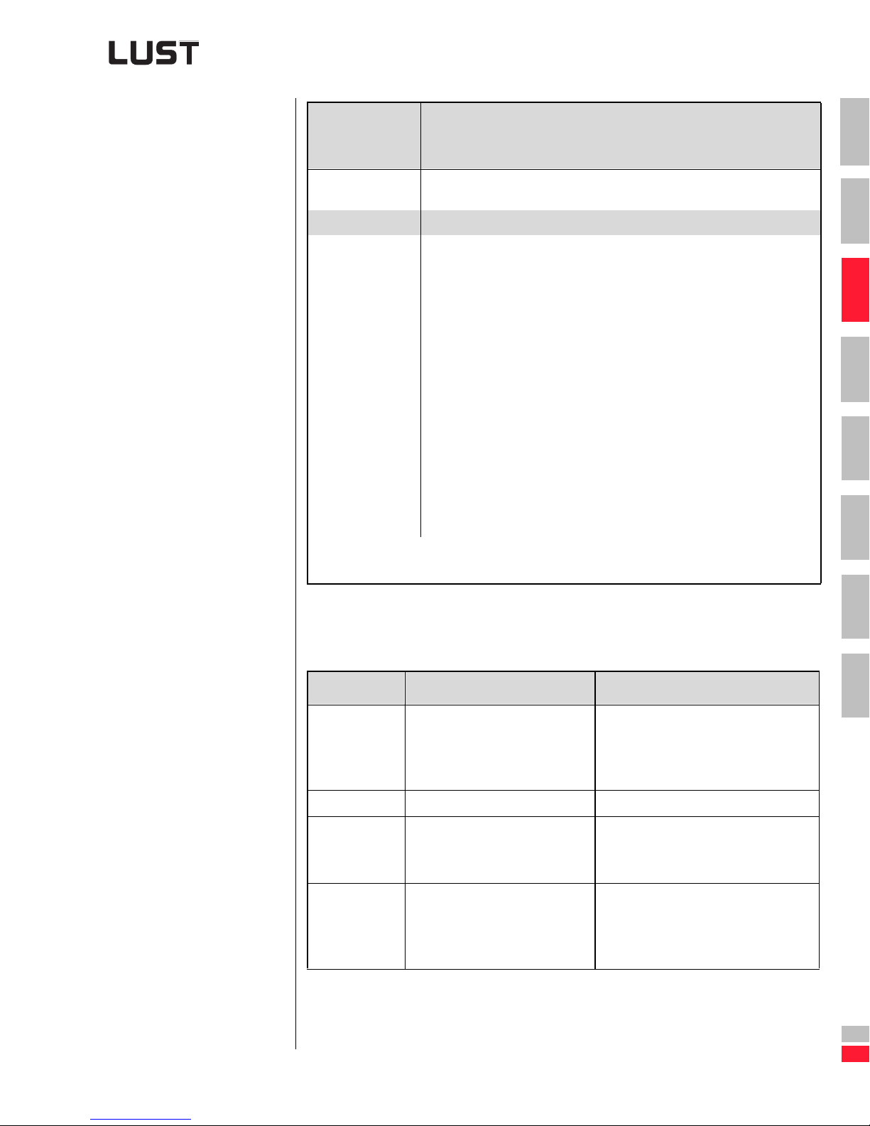
3 Selection of inverter module
3.1.1 Acceptance
tests
Acceptance tests /
Standards /
Directives
CE The inverter modules conform to the requirements for installation in a
machine or system under the terms of the Low Voltage Directive.
Approvals
Conformance to
standards
1) EMC = Electromagnetic compatibility
2) Motor cable length - See section 6.4
(in preparation)
cUL
• Fitting-out of power installations with electronic equipment
E50178
1)
•EMC
• EMC, line-borne and radiated interference emission
• All devices conform to the product norm
interference immunity
IEC 1000-4-2 / EN 61000-4-2
IEC 1000-4-3 / EN 61000-4-3
IEC 1000-4-4 / EN 61000-4-4
IEC 1000-4-5 / EN 61000-4-5
EN 50081-1 and EN 50081-2
IEC 55011 integrated radio interference suppression level A
for inverter modules to 7.5 kW.
For inverter mod ules 11 to 90 kW a wide range of filters is available to ensure co nformance to IEC 55011.
EN618000-3 for speed-adjustable electric drives.
Characteristic data
2)/B2)
1
2
3
4
5
6
Table 3.3 Acceptance tests/Standards
Explanation of the “Acceptance tests and standards” table
Standard Test Comments
EN 61000-4-2 • By touch
Discharge 6 kV
• In air
Discharge 8 kV
EN 61000-4-3 • 26-1000 MHz (10 V/m) Test of the electromagnetic field
EN 61000-4-4 • at control terminals 2 kV
• on mains and motor cable
Impulse voltage 4 kV
EN 61000-4-5 • Conductor / conductor
1 kV
• Conductor / ground
2 kV
Table 3.4 Explanation of the “Acceptance tests and standards” table
Test of immunity to electrostatic discharge (ESD)
Test of immunity to rapid transient
electrical interference (burst)
Immunity to voltag e surge
7
A
Engineering Guide CDA3000
DE
EN
3-5
Page 89
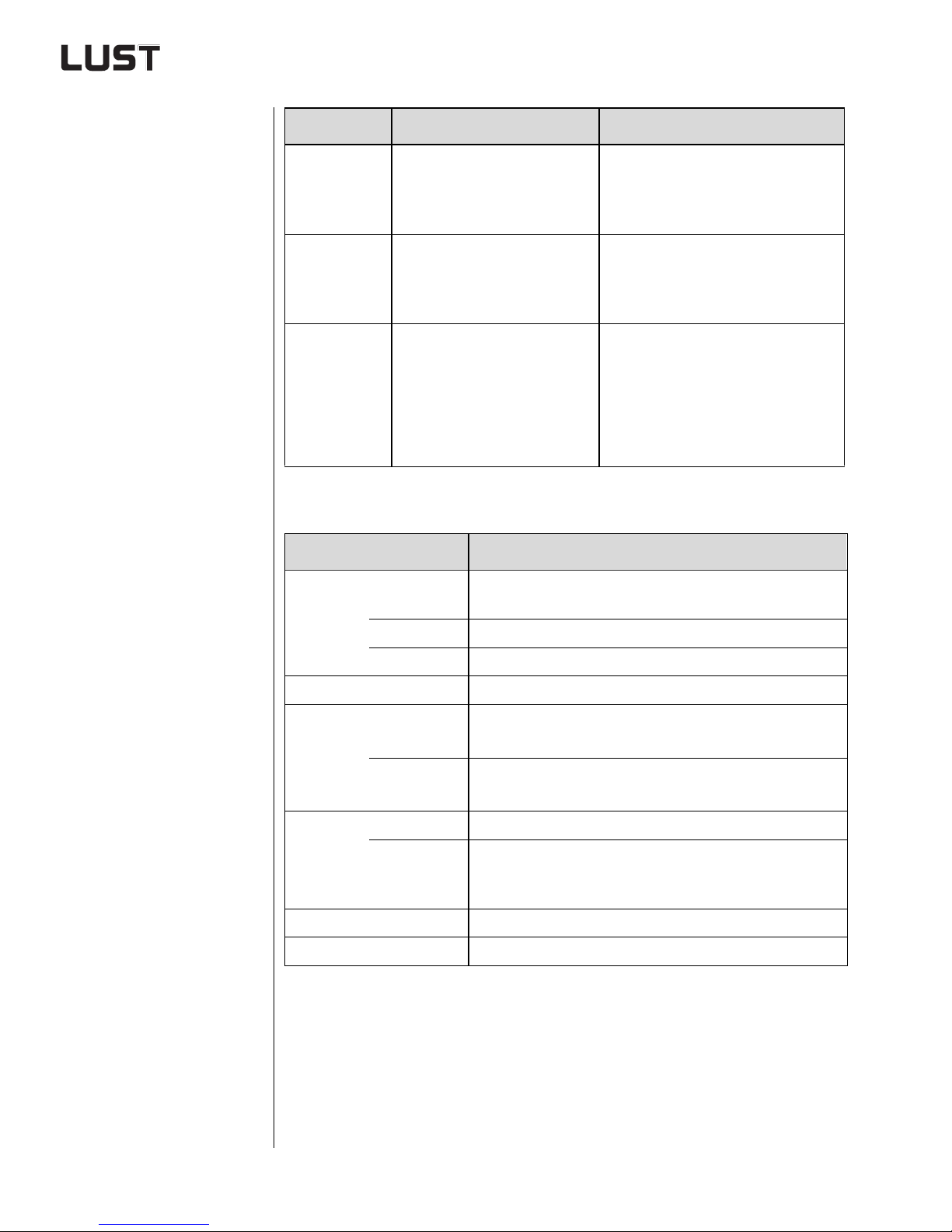
3 Selection of inverter module
Standard Test Comments
3.1.2 Ambient
conditions
EN 50081-1 • Residential and business
• Motor cable length - See
section 6.4
Protection against emission of electrical, magnetic and electromagnetic
interference and against conducted
interference
EN 50081-2 • Industrial
• Motor cable length - See
section 6.4.2
Protection against emission of electrical, magnetic and electromagnetic
interference and against lin e-borne
interference
EN 55011 • I ndustrial
Class A
Protection against line-borne interfer ence
• Residential and business
Class B
• Motor cable length - See
section 6.4
Table 3.4 Explanation of the “Acceptance tests and standards” table
Feature Characteristic data
Temperature range
in operation
-10 ... 45 °C with derating to 55 °C (BG1 ... BG5)
0 ... 40 °C (BG6 ... BG8)
in storage -25 ... +55 °C
in transit -25 ... +70 °C
Relative air humidity 15 ... 85 %, condensation not permitted
Mechanical
strength to
IEC 68-2-6
in stationary
operation
Vibration: 0.075 mm in frequency range 10 ... 58 Hz
2
Shock: 9.8 m/s
in frequency range >58 ... 500 Hz
in transit Vibration: 3.5 mm in frequency range 5 ... 9 Hz
2
Shock: 9.8 m/s
in frequency range >9 ... 500 Hz
Protection Device menu IP20 (NEMA 1)
Cooling
method
Cold plate IP20
Push-through heat sink IP54 (3...15kW)
Push-through heat sink IP20 (22...37kW)
Touch protection VBG 4
Power reduction See section 3.2.x
Table 3.5 Ambient conditions
Engineering Guide CDA3000
3-6
Page 90
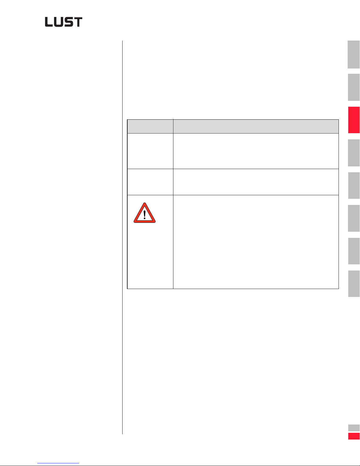
3 Selection of inverter module
3.1.3 Installation
and cooling
methods
The CDA3000 inverter module offers three different methods of installa tion and cooling:
➢ Cold plate
➢ Wall mounting with heat sink
➢ Push-through heat sink
General project planning notes
Subject Project planning notes
• Inverter modules 0.37 to 15 kW can be mounted next to each
Side clearance
Clearance above
and below
Table 3.6 Project planning notes
other with no gap.
• Above 22 kW a side clearance of 50 mm must additionally be
maintained.
• There must be a clearance of 100 mm above and below.
• Polluted cooling air (dust, fluff, oil, aggressive gases) may impair
the functioning of the inverter modules.
- Take adequate precautions; cold plate; separate
ventilation; installation of filters; regular cleaning etc.
• Do not exceed the permissible range of the operational cooling
temperature (see sections 3.1.2 and 3.2.14).
• Observe other ambient conditions (see section 3.1.2).
• Mounting orientation: Vertical on the rear of the switch cabinet or
other mounting surface.
• With “cold plate and push-through heat sink” cooling, comply
with the special conditions for discharge of power loss.
1
2
3
4
5
6
7
A
Engineering Guide CDA3000
DE
EN
3-7
Page 91
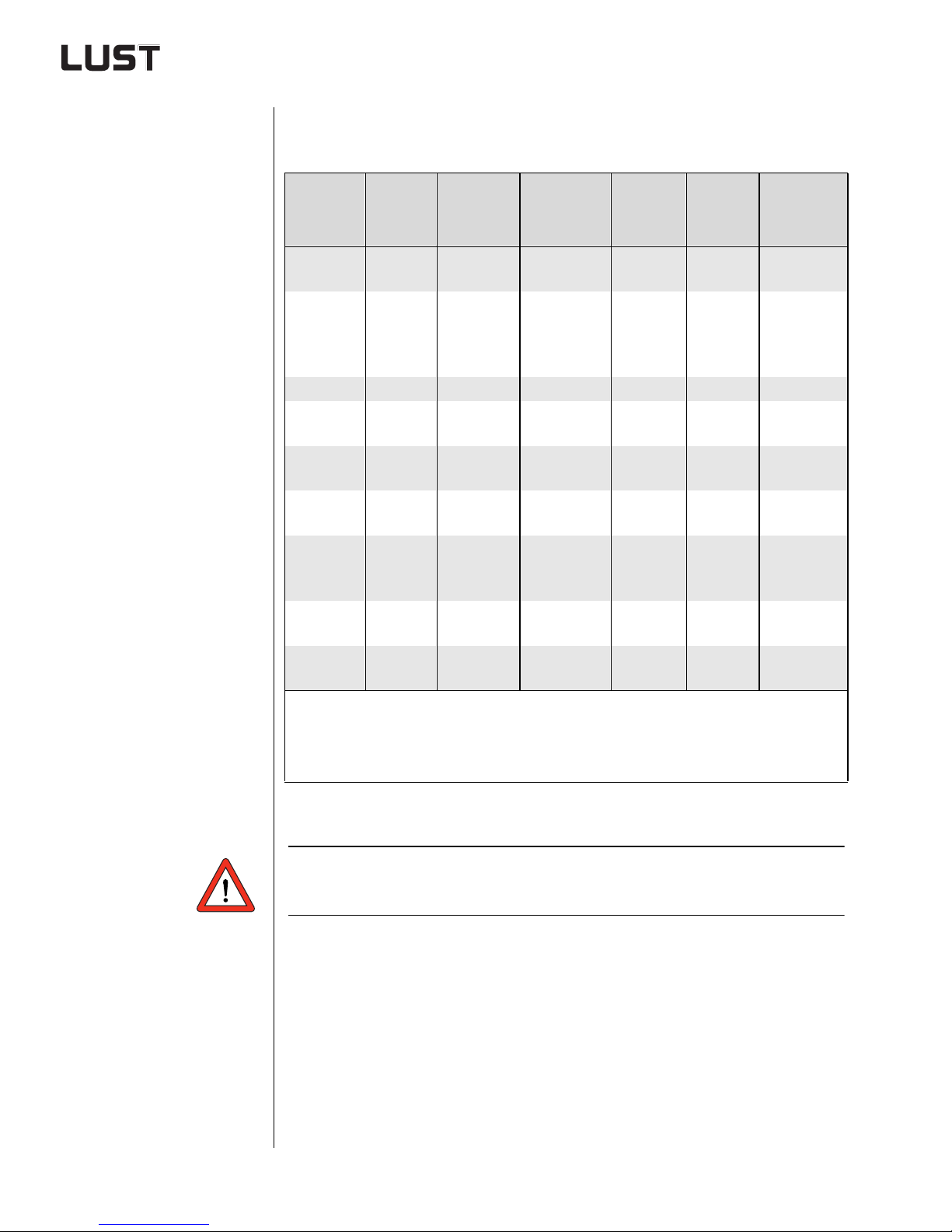
3 Selection of inverter module
Overview of the permissible cooling methods referred to size
and power output
Push-
through
heat sink
NO
NO
BG1
BG2
Size
Power
output
0.375kW
0.75 kW
1.1 kW
1.5 kW
0.75 kW
1.5 kW
Inverter
module
CDA32.00 3
CDA32.00 4
CDA32.00 6
CDA32.00 8
CDA34.00 3
CDA34.00 5
Power
loss
25 W
45 W
75 W
95 W
45 W
80 W
1)
Cold plate
YES
YES
Wall
mounting
2)
YES
2)
YES
BG2 2.2 kW CDA34.00 6 100 W YES YES NO
BG3
BG4
BG5
BG6
BG7
BG8
3.0 kW
4.0 kW
5.5 kW
7.5 kW
11 kW
15 kW
22 kW
30 kW
37 kW
45 kW
55 kW
75 kW
90 kW
CDA34.00 8
CDA34.01 0
CDA34.01 4
CDA34.01 7
CDA34.02 4
CDA34.03 2
CDA34.04 5
CDA34.06 0
CDA34.07 2
CDA34.09 0
CDA34.11 0
CDA34.14 3
CDA34.17 0
120 W
150 W
180 W
225 W
330 W
400 W
500 W
600 W
700 W
900 W
1100 W
1400 W
1700 W
YES YES
YES YES
YES YES
NO YES
YES
YES
YES
YES
NO YES NO
NO YES NO
3)
3)
3)
4)
1) With a power stage clock frequency of 4 kHz
2) See current curves in section 3.2.14
3) The push-through heat sink has IP54 protection
4) The push-through heat sink has IP20 protection
Table 3.7 Overview of inverter modules and possib l e cooling methods
At 8 kHz power stage clock frequency the power losses increase
by 40%.
Engineering Guide CDA3000
3-8
Page 92
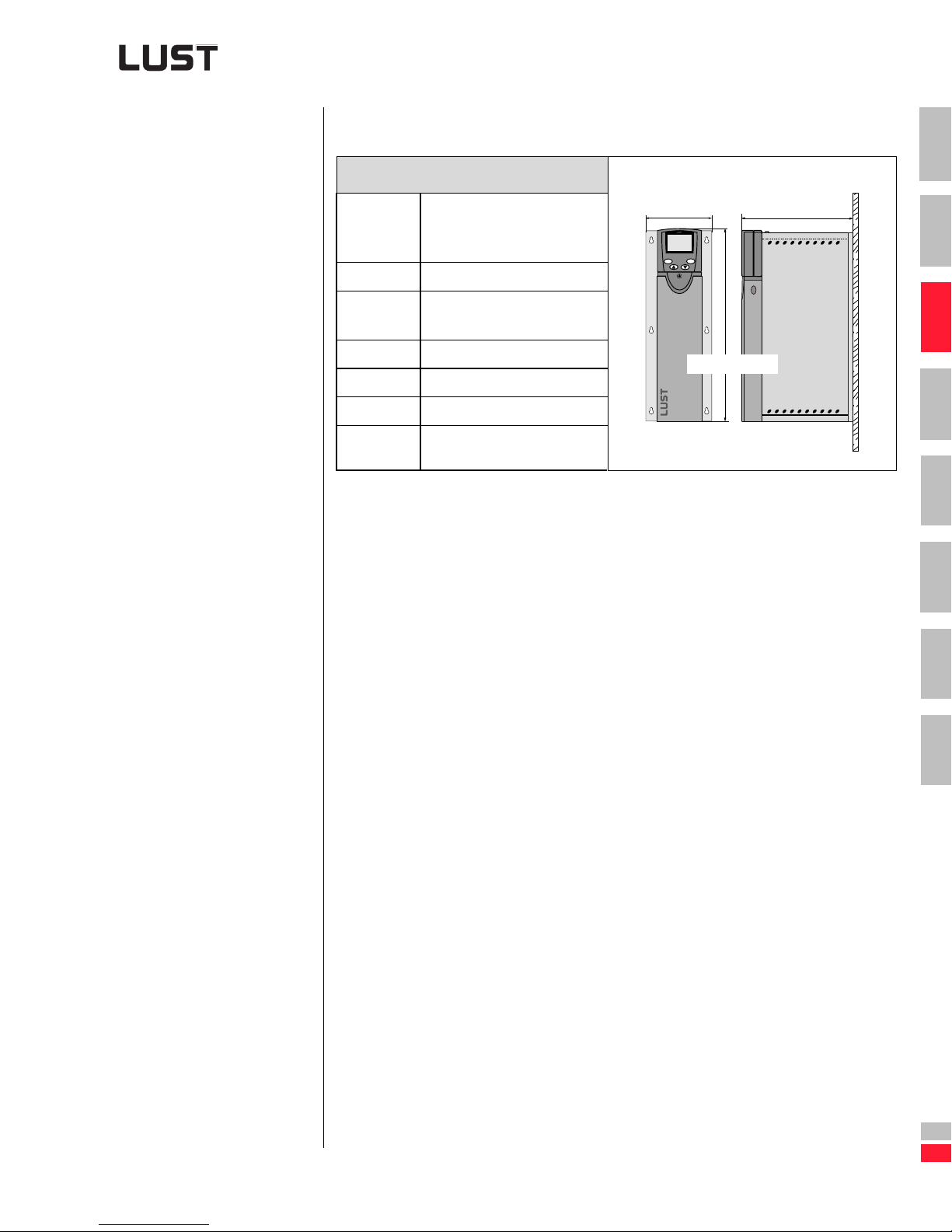
3 Selection of inverter module
“Cold plate” cooling method based on the example of size 3
(3 and 4 kW)
CDA3..., Cx.x
1
Installation Vertical on mounting plate
(heat-conducting) or cooling
profile, ) cold plate principle
Protection IP20
Cooling air
temperature
Weight 2.8 Kg
H (height) 303 mm
W (width) 100 mm
D (depth) 182.5 mm
Table 3.8 Cold plate installation and cooling method
45 °C (at 4 kHz switching
frequency of power stage)
W
stop
start
return
enter
CDA3..., Cx.x
H
D
2
3
4
5
6
Engineering Guide CDA3000
7
A
DE
EN
3-9
Page 93
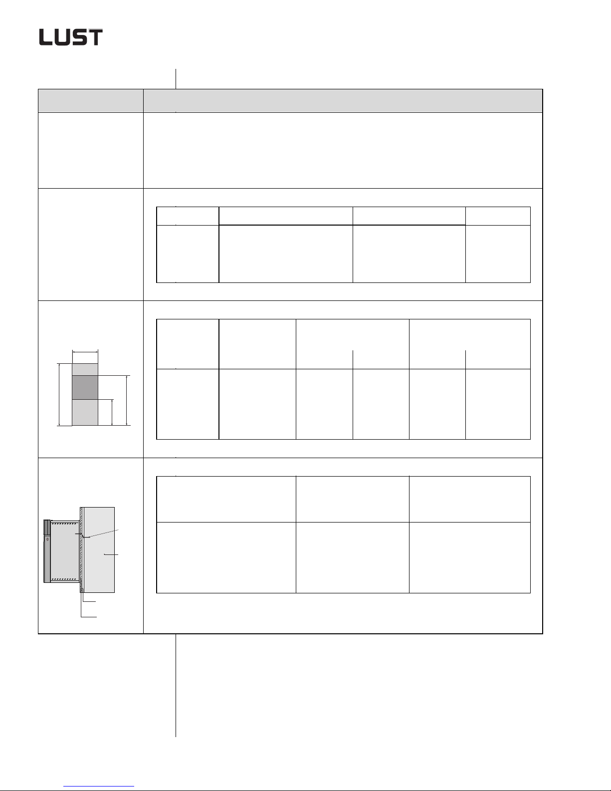
3 Selection of inverter module
Project planning notes, “Cold plate”
Subject Project planning notes
• Evenness of contact surface of 0.05 mm
Thermal connection to
cooler
RZR 6.3 = maximum roughness of contact surface
• Coat area between inverter module (“cold plate” backing plate) and cooler with heat transfer
compound (coat thickness 30-70µ).
• The temperature in the middle of the inverter module backing plate must not exceed 85 °C.
Size Power output Heat sink Housing
Distribution of
power loss
Active cooling area
B
H
a
Thermal resistance
R
Cooler
Heat transfer
compound
Mounting plate
CDA3000
BG 1/2
BG 3
BG 4
BG 5
Size
0.37 to 2.2 kW
3 to 4 kW
5.5 to 7.5 kW
11 to 15 kW
Power output
[kW]
Device basic area
[mm]
approx. 65%
approx. 70%
approx. 75%
approx. 80%
approx. 35%
approx. 30%
approx. 25%
approx. 20%
Active cooling area
[mm]
B H a b
BG 1
BG 2
b
BG 3
BG 4
BG 5
th
0.37 to 0.75 kW
1.1 to 2.2 kW
3 to 4 kW
5.5 to 7.5 kW
11 to 15 kW
Size
BG 1
BG 2
BG 3
BG 4
BG 5
70
70
100
150
200
Power output
[kW]
0.37 to 0.75 kW
1.1 to 2.2 kW
3 to 4 kW
5.5 to 7.5 kW
11 to 15 kW
193
218
303
303
303
50
90
120
65
80
165
200
260
215
300
Temperature lag between
active cooli ng area and cool er
[K/W]
R
th
0.05
0.05
0.03
0.02
0.015
Table 3.9 Project planning notes, “Cold plate”
Engineering Guide CDA3000
3-10
Page 94
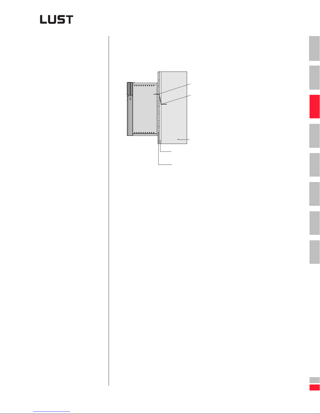
3 Selection of inverter module
Example: Heat transfer via a cooler
The inverter module has a
temperature evaluation facility
as standard.
The current temperature a t
point 1 of the heat sink is
displayed by way of parameter
427-KTEMP in subject area
_VAL (actual values).
• Inverter module CDA34.014
• Power stage clock frequency 4 kHz
Point 1: 85˚C, see table 3.9
Point 2: To be ascertained (max.
temperature on cooling plate)
Cooler
Heat transfer
compound
Mounting plate
CDA34.014
1. Power loss discharged by way of the mounting plate of the inverter
module.
The CDA34.014 has a power loss of 180 W (table 3.2).
75% of the power loss is discharged via t he mounting plat e (active cooling area) and 25% as radiated heat via the housing (table 3.9)
P
Mountingplate
= 180 W x 0.75 = 135 W
1
2
3
4
5
6
7
Engineering Guide CDA3000
2. Calculate temperature difference between mounting plate and cooling plate.
∆ϑ = P
1)
3. Maximum temperature at point 2 and on the cooler
ϑ
4. Calculation of the coole r:
• At point 2 the max. temperature of 82.3 °C must not be exceeded.
• 135 W of power loss must be discharged by way of the cooler.
• The exact solution depends on the cooler used, e.g. heat sink to air
or water, heat exchanger etc.
Mounting plate
See table 3.9
Point 2
= ϑ
Point 1
1)
x R
-DJ = 85 °C - 2.7 °C = 82.3 °C
= 135 W x 0.02 K/W = 2.7 K
th
3-11
A
DE
EN
Page 95
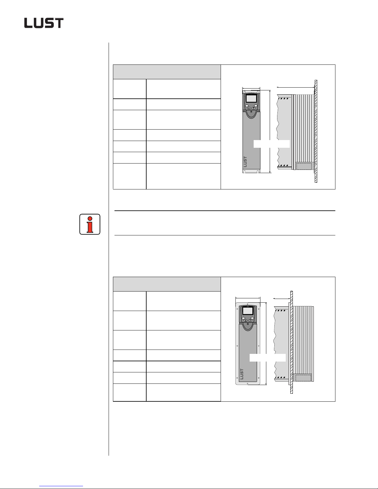
3 Selection of inverter module
“Wall mounting” cooling method based on the example of size 3
(3 and 4 kW)
CDA3..., Wx.x
Installation Vertical wall mounting with
W
D
heat sink
Protection IP20
Cooling air
temperature
45 °C (at 4 kHz switching
frequency of power stage)
Weight 3.7 Kg
H (height) 330 mm
stop
start
return
enter
CDA3..., Wx.x
H
W (width) 70 mm355 mm
D (depth) 250.5 mm
Table 3.10 Wall mounting installation and cooling method
With this cooling method the inve rter module can even be mounted on
non-heat-conducting surfaces.
“Push-through heat sink” coolin g method bas ed on the e xample
of size 3 (3 and 4 kW)
L
CDA3..., Dx.x
Engineering Guide CDA3000
Installation Vertical mounting with
W
D
push-through heat sink
Protection IP20 u nit s,
stop
start
return
enter
IP54 heat sink side
Cooling air
temperature
Weight 3.9 Kg
45 °C (at 4 kHz switching
frequency of power stage)
H
CDA3..., Dx.x
H (height) 340 mm
W (width) 110 mm
D (depth) 170.5 mm
Table 3.11 Push-through heat sink installation and cooling method
3-12
Page 96
3 Selection of inverter module
When the “push-th rough h eat si nk” co oling meth od is us ed, t he heat sink
of the inverter module can be mounted outside the switch cabinet, or
mounting space, in order to reduce the hea t generated. The power loss
split is dependent on size, and is shown in the following table.
Size Power output T o the outside To the inside
BG 3 3 to 4 kW 70% 30%
BG 4 5.5 to 7.5 kW 75% 25%
BG 5 11 to 15 kW 80% 20%
BG 6 22 to 37 kW 85% 15%
Table 3.12 Distribution of power loss wit h t he “push -through heat sink ”
cooling method
1
2
3
4
Size of inverter modules dependent on
cooling method
Size
BG 1 0.37 to 0.75
BG 2 1.1 to 2,2
BG 3 3 to 4 100x303x183 70x330x251 110x340x171 100 / 100
BG 4 5.5 to 7.5 150x303x183 120x330x251 160x340x171 100 / 100
BG 5 11 to 15 200x303x183 170x330x251 210x340x171 100 / 100
BG 6 22 to 37 no 250x375x325 250x411x248 100 / 100
BG 7 45 to 55 no 300x600x305 no 100 / 100
BG 8 75 to 90 no 412x540x370 no 100 / 100
1) Max. outer dimensions to be maintained
2) The bending radii of the cables must be taken into account for the mounting clearance below
Note: The modules can be mounted side-by-side. As from size 6 an additional side clearance of 50 mm is required.
Power output
[kW]
Cold plate
W x H x D
70x193x153 70x193x228 no 100 / 100
70x218x178 70x218x253 no 100 / 100
1)
Wall mounting
W x H x D
1)
Push-through
heat sink
W x H x D
1)
Clearance
above/
below
[mm]
5
2)
6
7
A
Engineering Guide CDA3000
Table 3.13 Size of inverter modules dependent on on cooling method
DE
EN
3-13
Page 97
3 Selection of inverter module
3.2 Extreme operating conditions
Safety instructions
While in operation, inverter surfaces can be conductive,
uninsulated, sometimes also moving or rotating, and hot, according to
their type of protection. This means that a f requency inver ter drive can
endanger human life.
To prevent serious physical injury or considerable materi al damage, only
qualified persons familiar with electrical drive equipment may work on the
equipment. Only those persons who are familiar with mounting, installing,
commissioning and operating inverters and have appropriate professional
qualifications shall be regarded as qualified. Those persons must read
the Operation Manual carefully before installation and commissioning,
and follow the safety instructions.
In this context the standards IEC 364 and CENELEC HD 384 or DIN VDE
0100 and IEC-Report 664 or VDE 0110 and na tional ac cident prevention
regulations or VBG 4 must be observed.
Repairs to the device may only be carried out by the manufacturer or by a
repair workshop approved by the manufacturer. Unauthorized opening
and unprofessional intervention could lead to physical injur y or material
damage.
Intended use
Inverters are components that are intended for installation in electrical
systems or machines.
The inverter may not be commissioned (i.e. it may not be put to its
intended use) until it has been established that the machine complies with
the provisions of EC Directive 89/392/EEC (Machinery Directive);
EN60204 is to be observed.
In addition to the Low Voltage Directive 73/23/EEC the harmonized standards of the prEN 50178/DIN VDE 0160 series in conjunction with EN
60439-1/DIN VDE 0660 Part 500 and EN 60146/DIN VDE 0558 a re to be
applied with regard to the inverte rs.
The technical data and the instr uc tions conc er n ing co nne ction condit ions
are given on the name plate and in the documentation, and are to be
observed under all circumstances.
The inverters are to be protected a gainst unauthor ized stress. In par ticular, components may not be bent, nor may insulation distances be altered
during transport and use.
Inverters contain components that are vulnerable to electrostatic accumulation and can therefore easily be damaged if incorrectly handled. Ens ure
that electrical components are not mechanically damaged or destroyed.
Engineering Guide CDA3000
3-14
Page 98
3 Selection of inverter module
When work is being carried out on live inverters, the app licable national
accident prevention regulations (e.g. VBG 4) are to be observed.
Electrical inst allation is to be car ried out in ac cordance with the relevant
regulations (e.g. cable cross se ction, fuses, grounding lead connec tion).
Other details are contained in the documentation.
Electronic devices are fundamentally not fail-safe. Users are themselves
responsible for ensuring that the dr ive is rendered safe if the device fails.
If the inverter is used for s pecial appl ications (e .g. subject to explosion hazards), the required standards and regulations (e.g. EN50014
and EN50018) must be observed.
1
2
3
4
5
6
7
A
Engineering Guide CDA3000
DE
EN
3-15
Page 99
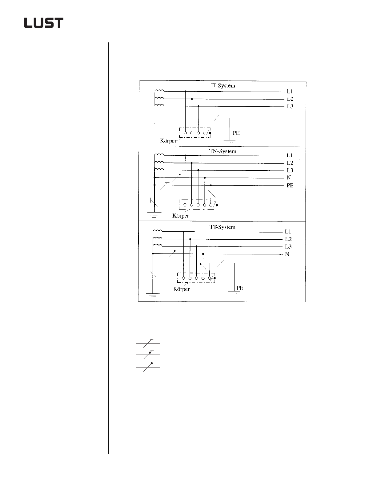
3 Selection of inverter module
3.2.1 Mains side/system condition
DIN VDE 0100-300: 1996-01 distinguis hes between three dif ferent mains
power systems. It is made especially cl ear how the IT system differs from
the TT and TN systems based on the means of groun d connection.
Figure 3.1 IT, TN and TT systems
First letter - Link from the supply system to the ground:
T Direct connection of a point to the ground
I Either all active parts isolated from ground or one point connected
Engineering Guide CDA3000
Grounding lead
PEN conductor
Neutral conductor
to ground via an impedance.
3-16
Page 100
3 Selection of inverter module
Second letter - Link from the bodies of the electrical sy st em to ground:
T Body ground ed directly, regardless of any grounding of a point of
the supply system
N Body grounded directly with the groun ded point of the supply
system (in AC systems the grounded point is generally the center
point or, if there is no center point, an outer conductor).
Voltage conditions in the IT system
1
2
In an IT system the voltages of the outer conductors are adjusted against
ground according to the voltage distribution by the discharge impedances. These impedances comprise the capacitors of the conductors and
those of the equipment ag ainst ground, and the parallel switched insulation resistors. If the said discharge impedances are equally large for every
conductor, all outer conductors likewise conduct the same voltage against
ground. High-resistance voltmeters connected between the outer conductor and ground display the same value. In three-phase AC systems this is
the star voltage; in AC systems half the conductor voltage is displayed.
Insulation monitors should therefore be connected symmetrically. If a
ground fault occurs on a conduct or, its voltage to ground collapse s. However, because the voltage between the conductors is maintained the
healthy conductors are raised to the conductor voltage against ground.
It should be considered that in the event of a ground fault on a conductor
in ungrounded systems the center point of the transformer takes on
phase voltage and the non-faulty outer conductors are raised to the outer
conductor voltage against ground.
This increased voltage load may result in puncture at a point with low
electrical insulation resistance, and this cause a double short circuit to
frame.
3
4
5
6
7
A
Engineering Guide CDA3000
DE
EN
3-17
 Loading...