

Page 1

XT 1 Plus, XT2 (Plus), XT3
Alarm panel
User Manual
Manual version 1.3 (Firmware 0.0.3.0K)
Page 2
Table of content
Table of content ............................................................................................................................................. 2
Introduction .................................................................................................................................................... 7
Difference of the alarm panels .......................................................................................................... 8
Disclaimer ......................................................................................................................................... 9
Important safety information ........................................................................................................... 11
If you find defects ............................................................................................................................ 12
Designated use ............................................................................................................................... 12
The most important chapters for the initial setup ........................................................................................ 13
Putting the LUPUSEC-XT2 (Plus) into operation ........................................................................................ 14
Place of installation ......................................................................................................................... 14
Connecting the XT1 Plus alarm panel ............................................................................................ 15
Connecting the XT2 (Plus) alarm panel .......................................................................................... 17
Connecting the XT3 alarm panel .................................................................................................... 19
Additional mounting information ..................................................................................................... 23
Description of the LEDs ............................................................................................................................... 24
Access to the web interface of the LUPUSEC-XT alarm panel ................................................................... 27
User interface of the alarm panel ................................................................................................................ 33
Home menu .................................................................................................................................... 38
Configure overview page ................................................................................................................ 42
Sensors ........................................................................................................................................... 46
List .................................................................................................................................................. 47
Edit sensor ...................................................................................................................................... 50
Add .................................................................................................................................................. 54
Range ............................................................................................................................................. 55
Universal remote control ................................................................................................................. 56
Smart home menu ......................................................................................................................... 58
Automation ...................................................................................................................................... 58
Home Automation settings.............................................................................................................. 62
Condition ......................................................................................................................................... 62
Schedule ......................................................................................................................................... 64
Action .............................................................................................................................................. 65
Examples ........................................................................................................................................ 68
Wireless plugs ................................................................................................................................ 76
2
Page 3
Cameras ......................................................................................................................................... 81
Capture ........................................................................................................................................... 84
Power consumption ........................................................................................................................ 85
Temperature history ........................................................................................................................ 86
Scenarios ........................................................................................................................................ 87
Alarm system .................................................................................................................................. 88
Settings ........................................................................................................................................... 88
Siren settings .................................................................................................................................. 95
Report ........................................................................................................................................... 100
PIN codes ..................................................................................................................................... 105
Settings ...................................................................................................................................................... 107
Network ......................................................................................................................................... 107
E-mail account .............................................................................................................................. 110
SMS account ................................................................................................................................ 112
SIM card........................................................................................................................................ 114
Device integration ......................................................................................................................... 117
System menu ................................................................................................................................ 120
Status ............................................................................................................................................ 120
Logs .............................................................................................................................................. 122
Password ...................................................................................................................................... 123
Firmware ....................................................................................................................................... 125
Factory reset .............................................................................................................................................. 128
Logout ......................................................................................................................................... 129
Remote access via the internet ................................................................................................................. 130
IPv4 / IPv6 problem ...................................................................................................................... 130
Port forwarding ............................................................................................................................. 131
Port forwarding – brief instructions (currently only in German): ..................................... 131
Access via the LUPUS app (for Android + iOS) ........................................................................... 132
Profile list ........................................................................................................................ 140
Usage of the alarm panel app ......................................................................................... 141
Alarm test................................................................................................................................................... 146
Description of sensors and controls .......................................................................................................... 147
Overview of sensors compatibility ............................................................................................................. 148
The internal I/O terminal of the XT3 ............................................................................................. 151
Integration of lamps of other manufacturers ................................................................................. 153
12 / 24 V wireless relay................................................................................................................. 156
3
Page 4

Connecting the 12 / 24 V wireless relay and putting it into operation ............................. 157
1 channel relay ............................................................................................................................. 159
Connecting the single channel relay and putting it into operation .................................. 160
1 channel relay ............................................................................................................................. 162
Connecting the double channel relay and putting it into operation ................................. 163
360° PIR motion detector ............................................................................................................. 165
Connecting the 360° PIR motion detector and putting it into operation .......................... 166
CO detector .................................................................................................................................. 168
Connecting the CO detector and putting it into operation:.............................................. 168
Curtain motion detector ................................................................................................................ 170
Connecting the curtain motion detector and putting it into operation ............................. 171
Door contact ................................................................................................................................. 174
Connecting the door contact and putting it into operation .............................................. 175
Door contact V2 ............................................................................................................................ 177
Connecting the door contact V2 and putting it into operation ......................................... 178
Dual-way motion detector ............................................................................................................. 181
Connecting the PIR / microwave motion detector and putting it into operation .............. 182
Electric meter ................................................................................................................................ 185
Connecting the electric meter and putting it into operation ............................................ 186
Emergency button ......................................................................................................................... 189
Connecting the emergency button and putting it into operation ..................................... 190
Glass breaking sensor .................................................................................................................. 192
Connecting the glass breaking sensor and putting it into operation ............................... 192
Glass breaking sensor V2............................................................................................................. 195
Connecting the glass breaking sensor V2 and putting it into operation ......................... 196
Heat detector ................................................................................................................................ 198
Connecting the heat detector and putting it into operation: ............................................ 198
Indoor siren ................................................................................................................................... 200
Connecting the indoor siren and putting it into operation ............................................... 200
Keypad .......................................................................................................................................... 206
Connecting the keypad and putting it into operation ...................................................... 207
Light sensor .................................................................................................................................. 211
Connecting the light sensor and putting it into operation ................................................ 212
Light switch V2 .............................................................................................................................. 214
Installation of light switch V2 ........................................................................................... 215
Lockswitch contact ........................................................................................................................ 219
Connecting the lockswitch contact and putting it into operation: .................................... 220
Magnetic lock ................................................................................................................................ 222
Installing the magnetic lock to the door and putting it into operation .............................. 223
4
Page 5

Mechanical lock ............................................................................................................................ 224
Installing the mechanical lock to the doorframe and putting it into operation ................. 225
Medical emergency controller ....................................................................................................... 227
Connecting the medical emergency controller and putting it into operation ................... 227
Outdoor keypad ............................................................................................................................ 229
Connecting the outdoor keypad with tag reader and putting it into operation ................ 231
Outdoor siren V2 ........................................................................................................................... 239
Connecting the outdoor siren V2 and putting it into operation ....................................... 240
Panic button .................................................................................................................................. 245
Connecting the panic button and putting it into operation .............................................. 245
PIR motion detector V2................................................................................................................. 246
Connecting the PIR motion detector V2 and putting it into operation ............................. 247
PIR network camera V3 ................................................................................................................ 250
Connecting the PIR network camera V3 und putting it into operation ............................ 251
Radiator valve thermostat V2 ....................................................................................................... 254
Installation of radiator valve thermostat V2 .................................................................... 256
Relay with power meter V2 ........................................................................................................... 260
Connecting relay with power meter for XT2 Plus and putting it into operation ............... 261
Remote control V2 ........................................................................................................................ 263
Connecting the remote control V2 and putting it into operation ..................................... 264
Remote controlled mains socket with power meter and ZigBee repeater .................................... 265
Connecting the wireless socket and putting it into operation ......................................... 266
Scenario switch V2 ....................................................................................................................... 268
Connecting the scenario switch V2 and putting it into operation .................................... 269
Sensor input .................................................................................................................................. 271
Connecting the sensor input and putting it into operation: ............................................. 272
Sensor input (9 fold) ..................................................................................................................... 274
Calibrating the sensor input (9 fold) ................................................................................ 276
Shutter relay V2 ............................................................................................................................ 278
Connecting the shutter relay V2 and putting it into operation ......................................... 281
Small indoor siren V2 .................................................................................................................... 284
Connecting the small indoor siren and putting it into operation ...................................... 285
Smoke detector V2 ....................................................................................................................... 287
Connecting the smoke detector V2 and putting it into operation .................................... 289
Status display ............................................................................................................................... 292
Connecting the status display and putting it into operation ............................................ 293
Tag Reader V2 ............................................................................................................................. 295
Connecting the tag reader V2 and putting it into operation ............................................ 296
Temperature sensor V2 ................................................................................................................ 298
5
Page 6

Connecting the temperature sensor and putting it into operation ................................... 298
Temperature sensor with display V2 ............................................................................................ 300
Connecting the temperature sensor and putting it into operation ................................... 300
Temperature sensor with external probe ...................................................................................... 302
Connecting the temperature sensor with external probe and putting it into operation ... 303
Top-hat rail relay ........................................................................................................................... 304
Connecting the top-hat rail relay and putting it into operation ........................................ 305
Universal IR controller .................................................................................................................. 307
Connecting the universal IR controller and putting it into operation ............................... 308
Learn and test IR signals ................................................................................................ 308
Installation ....................................................................................................................... 311
IR LED selection and operation ...................................................................................... 312
Upgrade dongle to XT2 Plus ........................................................................................................ 313
Vibration sensor ............................................................................................................................ 314
Connecting the vibration sensor and putting it into operation ........................................ 315
Water sensor ................................................................................................................................ 317
Connecting the water sensor and putting it into operation ............................................. 317
Water sensor V2 ........................................................................................................................... 319
Connecting the water sensor V2 and putting it into operation ........................................ 320
Wireless relay ............................................................................................................................... 322
Connecting the wireless relay and putting it into operation ............................................ 322
Wireless repeater V2 .................................................................................................................... 324
Connecting the wireless repeater V2 and putting it into operation ................................. 325
All information subject to change. Errors and omissions excepted. The latest manual can be
found on our website in the download section.
Manual version 1.3 (Firmware 0.0.3.0K)
6
Page 7
Introduction
Thank you for purchasing the XT alarm panel. Before you start the alarm panel, please
take the time to read the following safety and installation information carefully and
attentively.
This manual is for the alarm panels XT1 Plus, XT2, XT2 Plus, and XT3. Some chapters
and/or functions are not available for all models. To indicate a chapter that is not
applicable for all alarm panels, we use a green indication.
It is imperative to comply with these instructions in order to ensure the safe operation. If
you have any further questions, please contact your local retailer or LUPUS-Electronics
directly. Your LUPUS XT was developed and built with state-of-the-art technology and
complies with European and German standards.
Please keep this manual safely to be able to answer possible questions in the future. The
manual is an integral part of the product even in case it is resold to a third party.
Important:
We update and improve this manual regularly (new sensors/functions). Please
refer to our website to get the latest manual version for download as a pdf file:
(http://www.lupus-electronics.de/Alarm-Smarthome/).
We recommend updating the firmware of the alarm panel regularly to eliminate
minor errors and implement new functions. Please refer to the chapter
“Firmware” for more detailed information.
In case a sensor is no longer sold or was replaced by a newer model, the manual
of the old sensor is deleted from this manual for reasons of clarity. You can find
the manual of an old sensor on our website: https://www.lupus-
electronics.de/en/service/eol-product-downloads/
You can upgrade old XT2 alarm panels by means of a USB dongle in order to
support the latest sensors (not the SSL encryption though).
7
Page 8
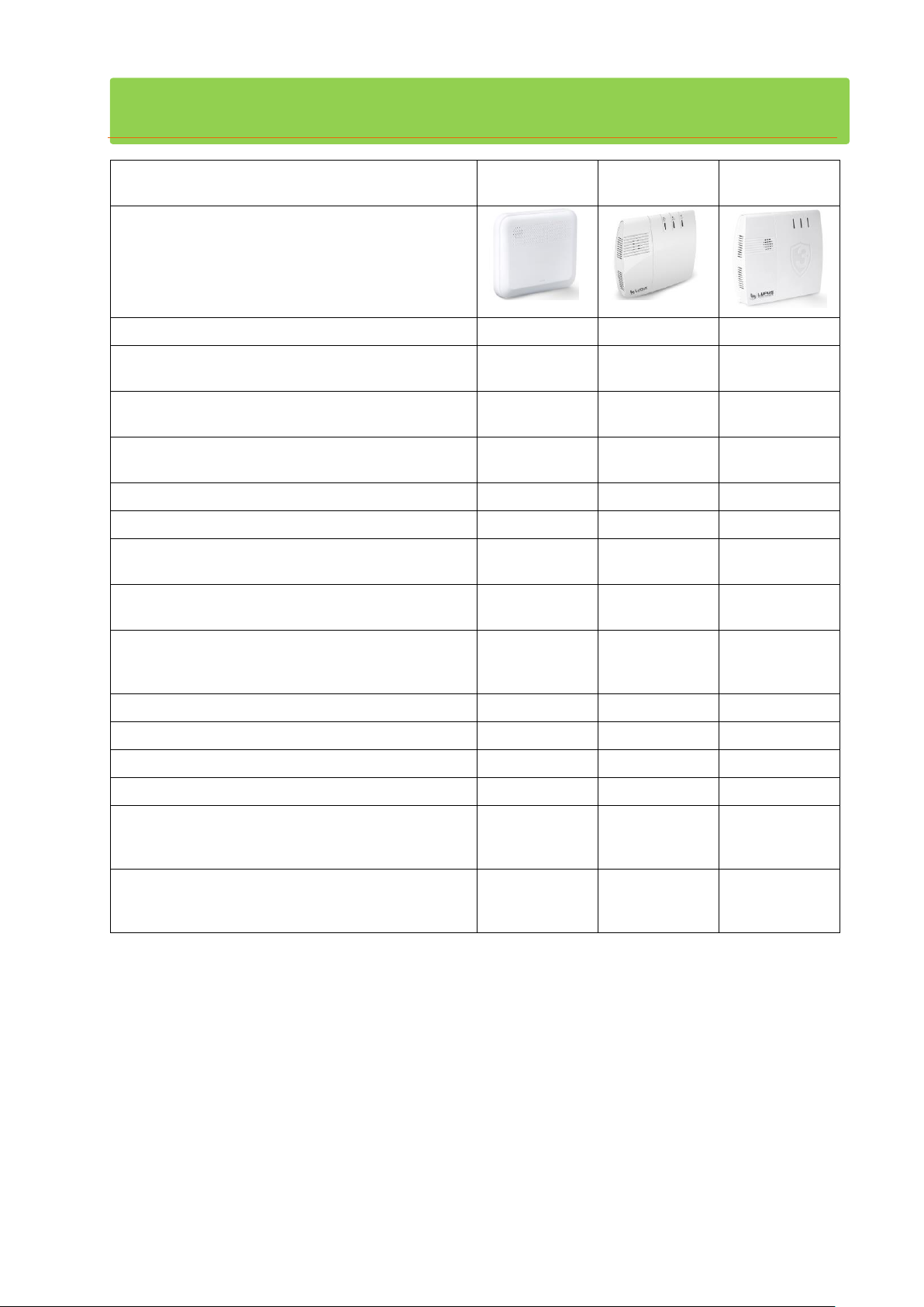
Difference of the alarm panels
Feature
LUPUS-XT1
Plus
LUPUS-XT2
(Plus)
LUPUS-XT3
Chassis
Access via LUPUS App.
Yes
Yes
Yes
Max. amount of sensors or Smarthome
devices.
80
160
160
100% data security: no server, no cloud. All
data is stored locally!
Yes
Yes
Yes
Second method for alarm notifications via
mobile communication (GSM).
No
Yes
Yes
Amount of connectable IP cameras.
4 8 8
Alarm via Push, SMS, and E-Mail.
Yes
Yes
Yes
Web-enabled. Controllable via PC, tablet,
smartphone, or Amazon Alexa.
Yes
Yes
Yes
More than 70 alarm, video, and Smarthome
accessories available from the manufacturer.
Yes
Yes
Yes
Professional 24/7 emergency management
system via Contact ID optionally available
(LUPUSEC 24).
Yes
Yes
Yes
Alarm notification via phone call.
No
Yes
Yes
EN 50131 Grad 2 certified.
No
No
Yes
Tampering protected chassis
Yes
No
Yes
SD-card slot.
No
No
Yes
Integrated rechargeable emergency battery
(Ni-MH) supplies the alarm panel for up to XX
hours.
21
17
17
Installation
Do it yourself
Do it yourself
Done for you
by certified
installers
8
Page 9
Disclaimer
This symbol is intended to attract the user’s attention to the potential
risk of dangerous unprotected voltage inside the housing. This may
lead to electric shock.
This symbol is intended to attract the user‘s attention to use and
maintenance instructions in the manual and documents enclosed to the
product.
All technical details and descriptions in this manual were compiled with the greatest care.
However, Lupus-Electronics cannot entirely exclude mistakes in this manual. Therefore,
we do not assume any legal responsibility or liability, which is result of wrong information
in this manual. Descriptions, technical illustrations, and technical data are subject to
change according to technical progress without notice. In addition, LUPUS-Electronics
reserves the right to change the product and the manual without prior notice. We do not
assume any guarantee with regard to the content of this document. We appreciate any
comments on mistakes or inaccuracies, which may help us to improve this product and
this manual.
9
Page 10
WARNING:
TO MINIMIZE THE RISK OF ELECTRIC SHOCK, YOU MUST NOT EXPOSE THIS
PRODUCT TO WET AND MOIST CONDITIONS AT ANY TIME.
All Lupus-Electronics products are lead-free and meet the requirements
stated under the European Directive on the Restriction of Hazardous
Substances (RoHS). This guarantees that the entire production process
and the product itself are free of lead and of all listed hazardous
substances.
This product was tested and complies with the regularities for a class of
digital devices stated under FCC part 15. These limits were specified to
provide reasonable protection against harmful exposure when operating
the device in a commercial environment. This product generates, uses and
may emit radio energy. It may in addition interfere with other radio
communication systems, if not installed or used according to this manual.
Using the device in residential areas may cause disturbances to be
possibly remedied at the user’s expense.
If installed properly according to this manual, the products
LUPUS – XT2 alarm panel (item. no. 12025; EAN: 4260195432512),
LUPUS – XT2 Plus alarm panel (item. no. 12045, EAN: 4260195433168),
LUPUS – XT3 alarm panel (item. no. 12120; EAN: 4260195433977), and
LUPUS – XT1 Plus alarm panel item. no. 12121; EAN: 4260195434240)
comply with CE regulations of Directive 1999/5/EG.. To avoid the risk of
electromagnetic interferences (e.g. with radios or radio traffic), it is highly
recommended to use shielded cables only.
10
Page 11

Important safety information
WARNING
The warranty claim will expire in case of damages resulting from the
non-observance of this manual.
We do not assume any liability for consequential damages.
We do not assume any liability for damages to persons and/or
material whatsoever, which result from improper handling or
noncompliance with the safety instructions. The warranty claim will
expire in such cases!
This alarm panel is equipped with a high-quality housing. However, please observe the
following safety regulations:
Handle the alarm panel with care, heavy vibration or bumps may damage this alarm
system.
Never open the alarm panel’s housing! This is dangerous and your warranty will expire
immediately.
Connect the alarm panel only to the approved and intended voltage. Operate the alarm
system only with the provided mains adapter. XT2 (Plus) and XT3 12V DC – 2 ampere.
XT1 Plus 9V DC – 1 ampere.
The socket must be located in an easily accessible, moisture-proof indoor location.
Do not expose the alarm panel to direct sunlight or strong heat, e.g. heaters.
Provide for sufficient ventilation of the system. Keep a minimum safety distance of 10
cm (4 inch) to all sides.
Do not install the alarm panel close to strong electric power lines or magnetic fields, as
this may impair the transmission quality significantly.
Do not install the alarm panel directly on iron or aluminum surfaces without isolating
the foot of the alarm panel from the floor, as this may impair the wireless transmission
significantly.
Do not install the alarm panel in moist, very cold, or very hot environments. Please
observe the maximum humidity and temperature limits (-10°C to +45°C (50F to 113F),
maximum 90 % relative humidity).
Do not expose the alarm panel to strong temperature changes. This could result in
short-circuits due to condensation.
The alarm panel may not get in contact with liquids of any kind.
Persons (including children) with limited physical, sensory, or mental abilities and/or
lacking experience and/or knowledge must not use this product.
Keep children away from the product and other connected electrical appliances at all
times. The alarm panel includes cables, which can strangle children, and small parts
they can swallow. Lay cables expertly so that they are neither bent nor otherwise
damaged. Assemble the alarm panel out of children’s reach. Do not leave packaging
materials unattended, as they may be dangerous for playing children.
Use a damp cloth to clean the alarm panel’s surface. Afterwards, dry the surface.
Cleaning agents will damage the surface.
11
Page 12

If you find defects
If you notice any kind of defect, disconnect the alarm panel from the power supply and
contact your retailer or LUPUS-Electronics directly. Any further usage of the system may
lead to fire or electric shock!
Designated use
This alarm panel is intended for property security purposes. Install the alarm panel
indoors only. Any other use than described in this manual is not permitted and will lead to
the expiry of any warranty or guarantee as well as to the exclusion of liability. The same
applies to modifications and retrofitting.
Information on disposal:
Do not dispose of the device with domestic waste!
This product complies with the EU Directive on waste electrical and electronic
equipment (WEEE) and therefore must not be disposed of with domestic waste.
Dispose of the device via your local collection point for waste electronic
equipment!
This product contains software programs subject to the GPL free software license.
This product contains software that was developed by third parties and/or software
subject to the GNU General Public License (GPL) and/or the GNU Lesser General Public
License (LGPL). We will send you the source code of these programs on request. The
GPL and/or LGPL code used and offered in this product is EXCLUSIVE OF ANY
GUARANTEE WHATSOEVER and is subject to the copyright of one or several authors.
For further details, please refer to the GPL and/or LGPL code of this product and to the
terms of use of GPL and LGPL.
You can read the complete license text at http://www.gnu.org/licenses/gpl-2.0.html.
For an unofficial German translation, please go to
http://www.gnu.de/documents/gpl.de.html
Conformity:
The declaration of conformity is available at http://www.lupus-electronics.de in the
download section of the respective product. Alternatively, you can request us directly to
send you the declaration of conformity by writing to:
LUPUS-Electronics GmbH
Otto-Hahn-Str. 12
D-76829 Landau
[email protected]
12
Page 13

The most important chapters for the initial setup
Beginning with the chapter “home menu,” this manual covers the menus of the alarm
panel according to the layout of the browser interface. For the initial setup, several of
the sub-menus are not important and can be skipped at first. Following the most
important chapters for the initial setup are listed:
1. Installation
Installation of the alarm panel, first access via the browser interface in your
local area network (LAN).
Chapter: Putting the alarm panel into operation (including
subchapters)
2. Adding of sensors
Adding / connecting sensors to the alarm panel
Detailed manuals of the individual sensors
Chapters: Menu “Sensors” “Add”
Manuals of the sensors and devices
3. Elementary settings
The elementary settings of the alarm panel
Chapters: Menu “Sensors” “List” “Edit” sensors
“Alarm panel” “Settings” “General settings”
“Alarm panel” “Siren settings” “Sound settings”
4. Alarm notification
Setting up the notifications in case of an alarm
Chapters: “Alarm panel” “Report”
5. Remote access via the internet
Detailed information, examples, and manuals to setup a port forwarding in
your router and access the alarm panel via browser or App (Android &
iOS).
Chapters: Menu “Network”
Remote access via the internet
6. Checking the functions of the alarm panel
System errors, arming and disarming the alarm panel, triggering and
controlling an alarm.
Chapters: Menu “Home”
The user interface of the alarm panel
Test / Simulation of a break in
7. Smarthome
Configuration of Smarthome rules including examples
Chapter: Menu “Smarthome”
13
Page 14

Putting the LUPUSEC-XT2 (Plus) into operation
The following pages describe the installation and start-up of the alarm panel
systematically. To avoid damages to the system, please observe these instructions in
detail and read the manual carefully before you start.
Remove the alarm panel from the packaging. Please check immediately after the delivery
for possible transportation damages and whether the product’s scope of delivery. In case
of damages or missing items, contact your retailer immediately.
WARNING
When in doubt do not assemble, install, and wire the alarm panel by
yourself, but hire a specialized electrician. Improper and unprofessional
execution of works at the power supply system pose a danger to you and
other persons.
Place of installation
The place of installation is crucial for the smooth operation of the system, as all sensors
are connected to the alarm panel wirelessly (868 MHz or 2.4 GHz). Therefore, the alarm
panel should be installed at a central location, in order to ensure the shortest possible
transmission distances to all sensors, as well as, an Ethernet connection to your router
or switch. The wireless transmission range of the alarm panel can be enhanced by using
a wireless repeater. When choosing the place of installation, please note the “important
safety information” above.
Important
The XT2 (Plus) is not equipped with a tampering contact. We advice you to use a
motion detector to trigger an instant alarm if anyone approaches the alarm panel while it
is in arm mode.
The XT1 Plus and XT3 are equipped with a tampering protection, nevertheless, we
would also advise you to follow the same security arrangements as with a XT2 (Plus).
14
Page 15
Connecting the XT1 Plus alarm panel
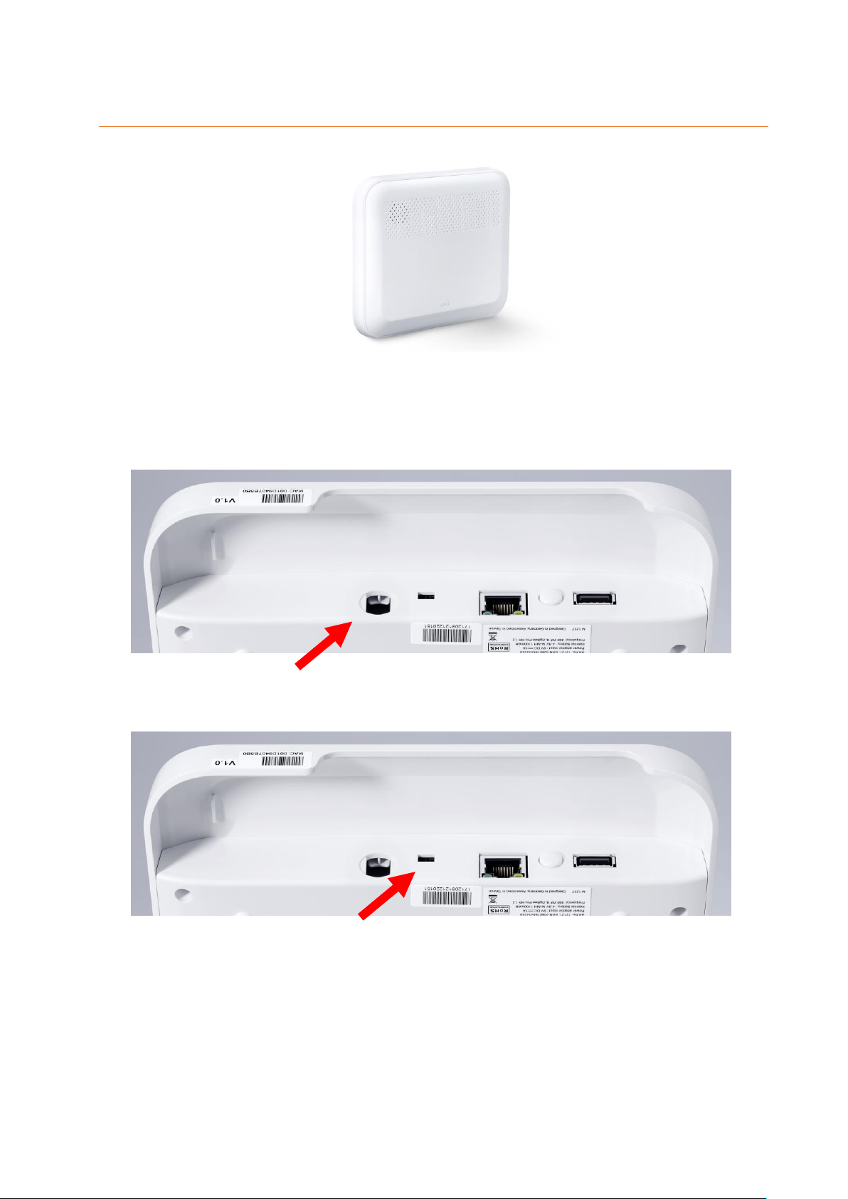
1. You need to install the XT1 Plus at a wall. For the mounting, screws, dowels, and a
wall mount are included. Screw the wall mount unto a wall and observe the
information given in the chapters “important safety information” and “place of
installation”.
2. Insert the included mains adapter into the XT1 alarm panel and twist the plug by 90°.
This protects the mains adapter against removal.
The alarm panel requires approx. 30 seconds to boot.
3. Turn the emergency battery on by moving the switch to the “ON” position (towards
the mains adapter input).
Please note:
In case of power failure, the internal battery can supply the alarm panel with
power for approx. 21 hours.
It takes approx. 6 to 9 hours to fully charge the emergency battery!
In case of a power failure, it takes at least three minutes until the alarm panel will
notify you.
15
Page 16

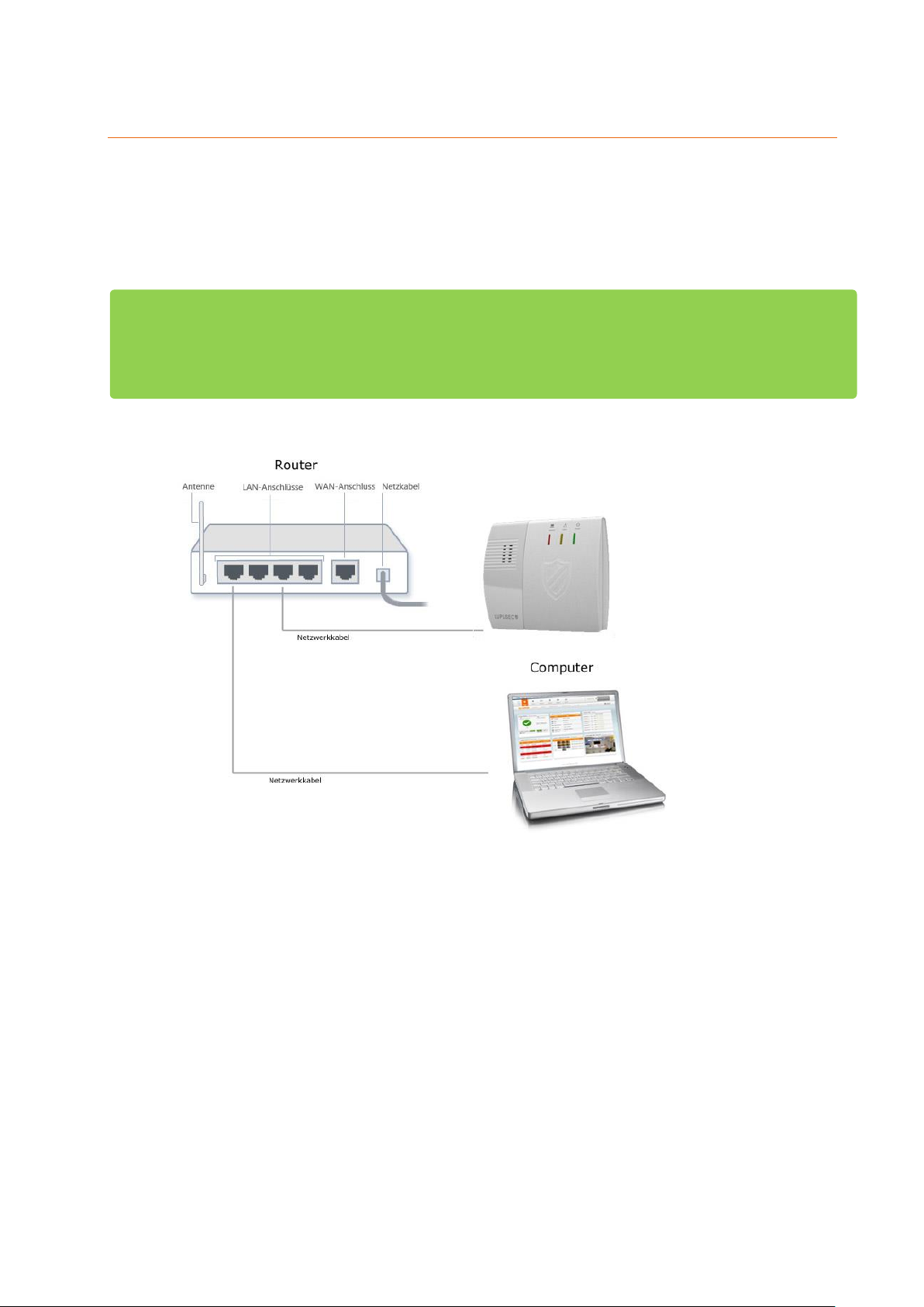
4. Connect the LAN cable to the alarm panel and then connect it to an internet router.
5. Mount the XT1 alarm panel to the wall mount. Make sure that the alarm panel locks
to the wall mount.
Description of the connectors:
1. Power supply connection
2. Battery on/off switch
On towards the power supply connector / off towards the LAN port
3. LAN port
4. Reset button
5. USB port
Currently no function
6. Mounting holes
For wall installation. The tampering contact of the alarm panel closes when the
alarm panel is locked onto the wall mount.
16
Page 17
Connecting the XT2 (Plus) alarm panel
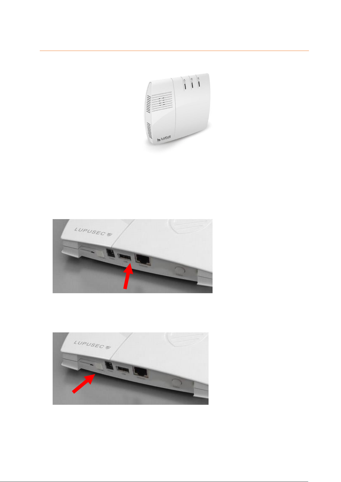
1. You can mount the XT2 (Plus) on a wall or place it on top of any even surface.
Please note:
For a wall installation, screws, dowels, and a drilling template are included. You need
to remove the rubber covers at the bottom of the alarm panel for an installation on a
wall.
2. Connect the provided mains adapter to the LUPUSEC-XT2 (Plus).
The alarm panel needs about 30 seconds to boot.
3. Remove the rubber cover from battery compartment on the back and turn the battery
switch to ON (left away from the power supply input).
Please note:
In case of power failure, the internal battery can supply the alarm panel with
power for approx. 12 hours.
It takes approx. 6 to 9 hours to fully charge the emergency battery!
In case of a power failure, it takes at least three minutes until the alarm panel
17
Page 18
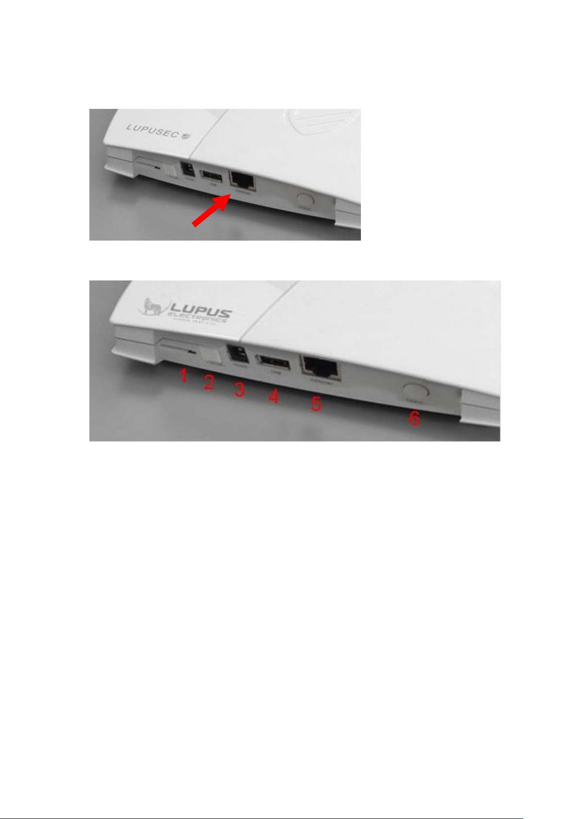
notifies you.
4. Connect the LAN cable to the alarm panel and then connect it to an internet router.
Description of the connectors:
1. (Mini) SIM card slot
2. Battery on/off switch
3. Power supply connection
4. USB port for “upgrade dongle to XT2 Plus”
5. LAN port
6. Learn button
18
Page 19
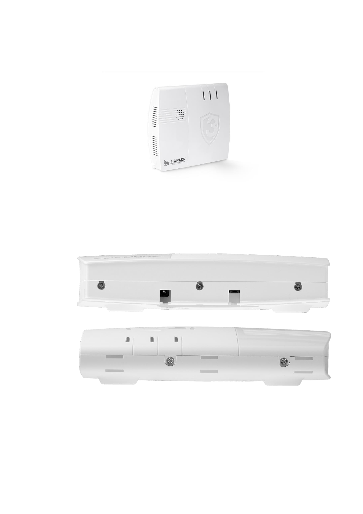
Connecting the XT3 alarm panel
According to the EN 50131 certification, it is required to install the alarm panel firmly to a
wall. All connectors are inside the chassis. Screws, dowels, and an installation template
are included.
1. Use a screwdriver to open the three screws at the bottom and the two screws
at the top of the alarm panel.
Bottom:
Top:
2. Open the chassis by moving the top towards the LEDs and the bottom in the
opposite direction (see following figure). Do not use force to open the chassis!
19
Page 20
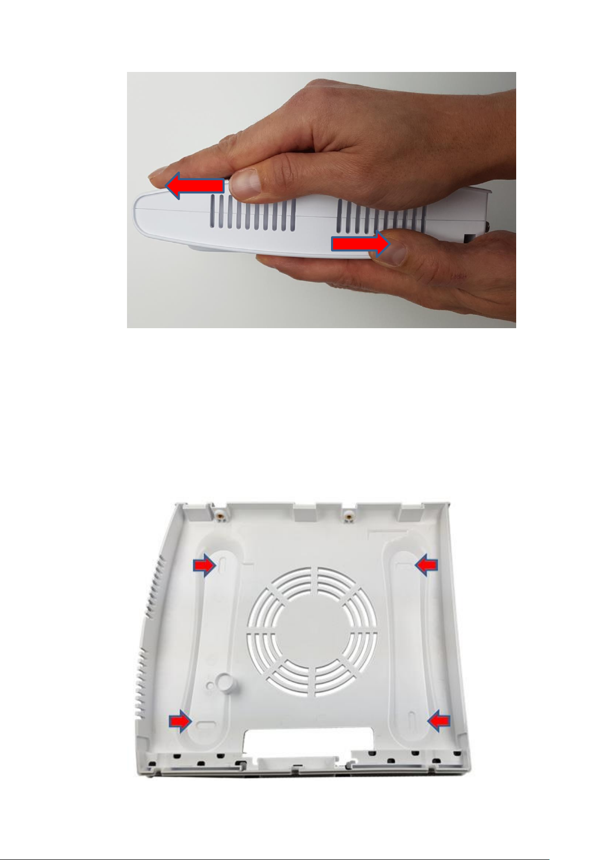
3. The place of installation is crucial for the smooth operation of the system, as all
sensors are connected to the alarm panel wirelessly (868 MHz or 2.4 GHz).
Therefore, the alarm panel should be installed at a central location, in order to
ensure the shortest possible transmission distances to all sensors, as well as,
an Ethernet connection to your router or switch. The wireless transmission
range of the alarm panel can be enhanced by using a wireless repeater.
4. Drill through the indicated points at the back of the alarm panel. Use the
installation template to drill holes for the dowels. Check the wall for wiring and
pipes before drilling the holes.
Back:
20
Page 21
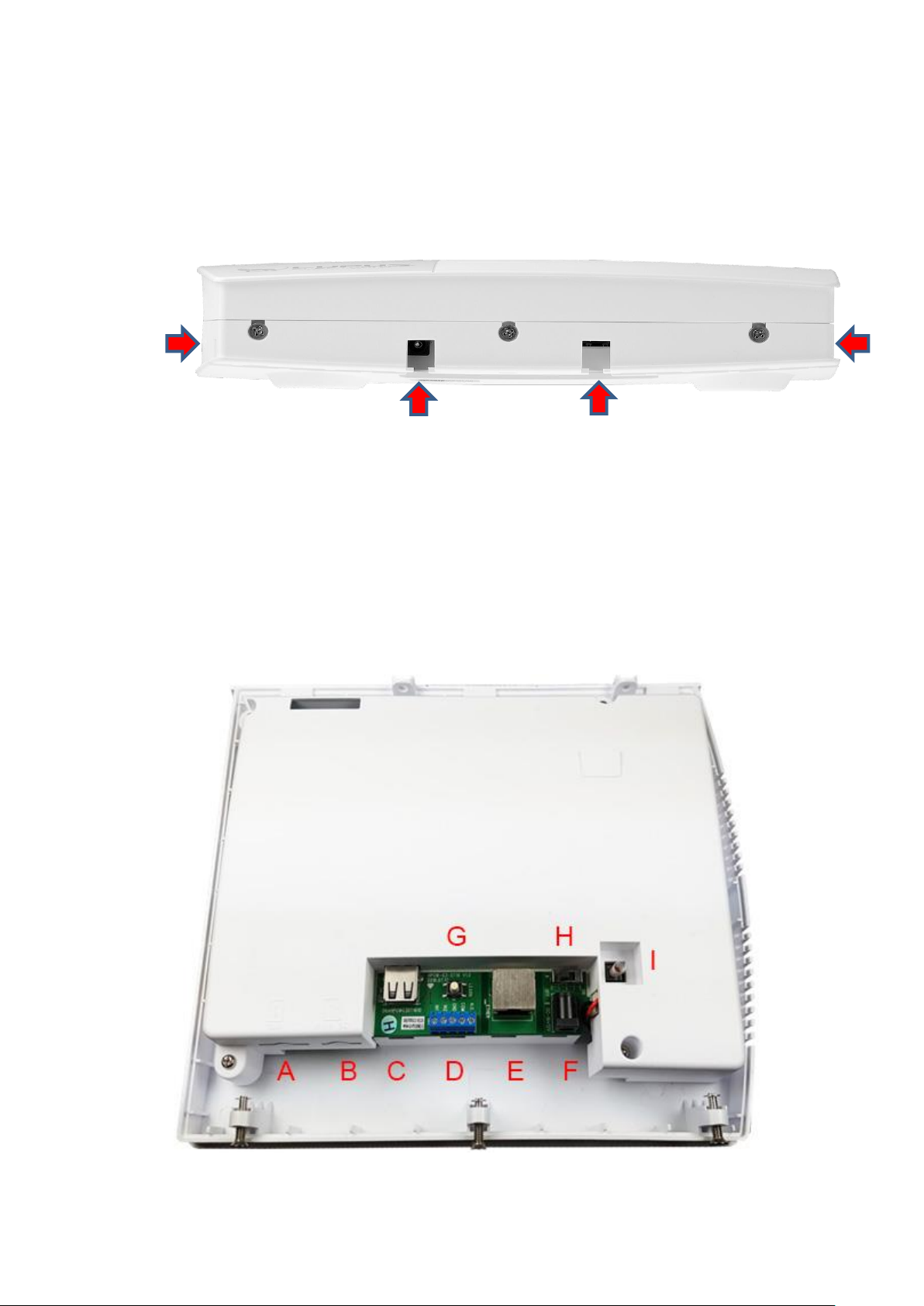
5. Drill the holes fitting to the included dowels.
Please note:
Before screwing the back to the wall, you need to lay all cables through the
cable opening of the alarm panel. After the installation, you would need to
unscrew the back from the wall again to lay the cables through the cable
opening.
6. Switch the emergency battery on (H – towards the tampering contact / off
towards the LAN port).
7. Connect the LAN cable to the LAN Port.
8. Connect the mains adapter to the power supply connector.
9. Screw the back of the alarm panel to the wall.
10. Reattach the front of the alarm panel to the back (without using force – start
with the top). Use the five screws to fix the front to the back again.
11. Plug the mains adapter into a power socket. The alarm panel requires approx.
30 seconds to boot.
Description of the connectors:
A. SIM slot
21
Page 22

Allows you to inset a Mini SIM card (not included) to use a second alarm route
via SMS or phone call.
B. Micro SD-card slot
Allows you to save recordings of connected LUPUS cameras (not yet
implemented).
C. USB port
Currently no function.
D. I/O terminal (2x alarm input / 1x alarm output)
Allows you to connect wired devices. Dry contact input and output. See chapter
I/O terminal for more information.
E. LAN port
F. Power supply connector
G. Reset button
H. Battery on/off switch
In case of power failure, the internal battery can supply the alarm panel
with power for approx. 16 hours.
It takes approx. 6 to 9 hours to fully charge the emergency battery!
In case of a power failure, it takes at least three minutes until the alarm
panel
I. Tampering contact
Opening the chassis triggers an alarm.
22
Page 23
Additional mounting information
After booting, the Error LED of the alarm panel lights up and a warning signal
sounds every 30 seconds. The cause is that usually no SIM card (not XT1 Plus) is
inserted upon the first start-up and that the emergency battery is not fully charged.
The alarm panel interprets both as a system error. The chapter “Status” describes
how to ignore such errors.
As soon as the XT1 Plus is removed from the wall mount or the chassis of the
XT3 is opened, the tampering contact opens and a tampering alarm is triggered.
In the default settings, a tampering alarm does not sound a siren alarm when the
alarm panel is disarmed. This can be changed in the menu “Alarm system”
“Settings” “Area settings” “Tamper alarm”.
The alarm panel is not equipped with a WLAN module. Hence, to use the
network connection a Ethernet cable needs to be connected at all times.
23
Page 24

Description of the LEDs
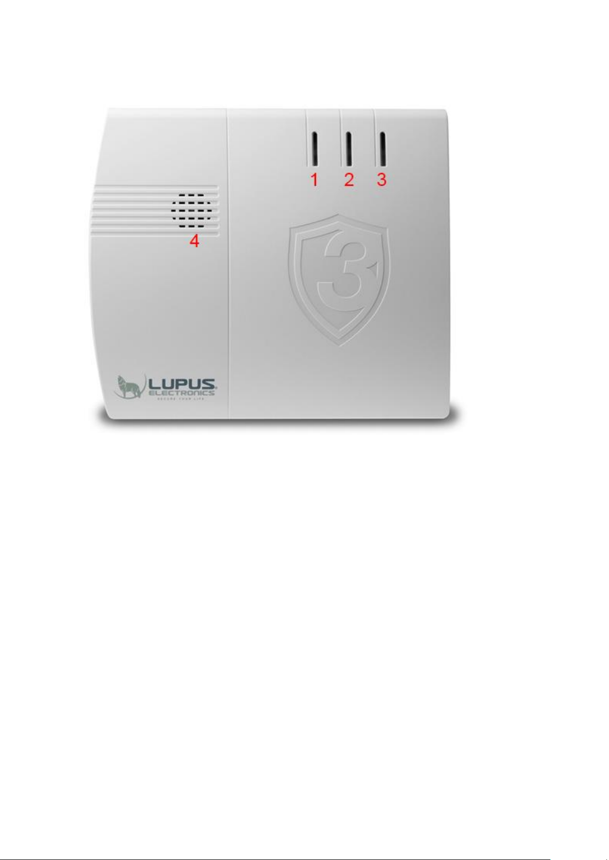
The LUPUS XT alarm panel has three different control LEDs, which inform you about the
alarm panel’s status.
XT1 Plus
XT2 (Plus)
24
Page 25
XT3
1. Error LED
Red = system error (list via “System” “Status” “Panel”)
Off = system in correct state
2. Area 1 LED
Red = Area 1 in armed mode (Arm)
Green = Area 1 in Home mode (Home 1, Home 2, Home 3)
Flashes red = Alarm in Area 1
o Switch the flashing off by disarming Area 1
Flashes green + Area 2 LED flashes green = Alarm panel is in Add sensors
mode or Test range mode
Off = Area 1 is disarmed, the system memory does not contain any alarm
3. Area 2 LED
Red = Area 2 in Armed mode (Arm)
Green = Area 2 in Home mode (Home 1, Home 2, Home 3)
Flashes red = alarm in Area 2
o Switch the flashing off by disarming Area 2
Flashes green + Area 1 LED flashes green = Alarm panel is in Add sensors
25
Page 26

mode or Range test mode
Off = Area 2 is disarmed, the system memory does not contain any alarm
Please note:
The LEDs of the XT2 (not Plus) area 1 LED flashes green and area 2 LED red during
learn or range test mode.
4. Speaker
Important:
The alarm panel has two areas. When adding a new sensor, the sensor receives an
individual number (zone) for the area in which the sensor is added. By default, it is a
consecutive numbering. The zone number can also be changed later on.
Both areas can be controlled separately, thus, a single XT alarm panel can secure a semi-
detached house.
Each area features five modes: arm, home 1,2, or 3, and disarm.
How the alarm panel reacts in the different modes depends upon the settings of the
individual sensors (see chapter “Edit sensor”). Hence, you can secure the shell of you
home while the motion detectors in the interior of your home will not trigger an alarm while
you are at home.
26
Page 27
Access to the web interface of the LUPUSEC-XT alarm panel
The alarm panel is controlled via a browser-based user interface, which is structured like
a website. On this website, you can control all system functions of the alarm panel, add
and edit sensors, arm or disarm the alarm panel, check for open windows or doors, and
view pictures from your LUPUSNET HD network cameras and recorders (if installed and
connected).
To open the main menu of the alarm panel, proceed as follows:
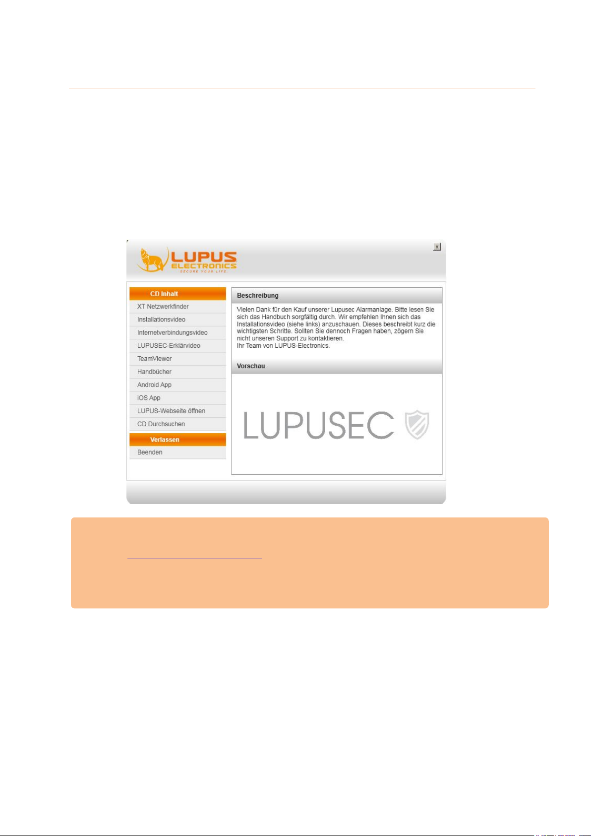
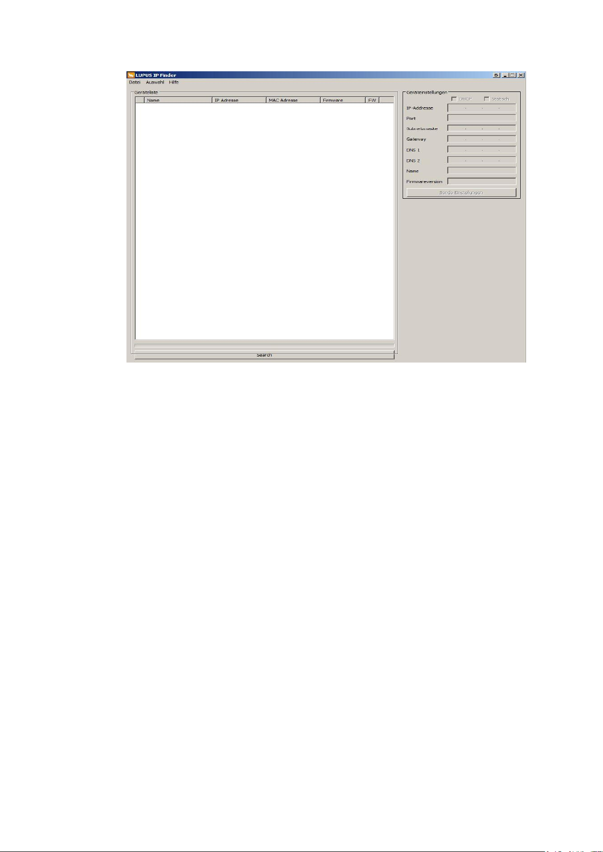
1. Insert the CD and start the network / IP Finder. If you already know the IP
address of the alarm panel, you can directly access it via your browser.
Please Note
The IP Finder for MacOS can be downloaded from our homepage
It is also possible to access the alarm panel via your Android or iOS
2. Click on “Search” in the bottom of the page to scan your network for your
(www.lupus-electronics.de).
smartphone. More information for the mobile access can be found in the
chapter “access via the LUPUSEC App”.
alarm panel.
27
Page 28
Please Note:
To gain access to the alarm panel, it must be within the same logical
network (e.g. 192.168.100.X) as the accessing device (PC/notebook).
If this is not the case, please check your network connection. More
information can be found in the chapter “Settings” “Network”.
If you do not (want to) use a DHCP server, you can also set a static IP
address for the alarm panel via the IP Finder. If you define a static IP
address, all settings are important and need to be correct to guarantee
that the alarm panel works correctly. In most cases, you can use the IP
address of your router as gateway, DNS 1, and DNS 2. More information
can be found in the chapter “Settings” “Network”.
In case you want to connect the alarm panel directly with your computer,
you need to use an Ethernet crossover cable.
3. Double-click on the alarm panel or, alternatively, click with the right mouse
button on “Open” to establish a connection to the alarm panel via your standard
browser. A login window opens.
All communication with the alarm panel is encrypted via SSL/TLS 1.2 SHA-
256bit RSA.
The waring “This connection is untrusted” does not mean that your
communication with the page in question was compromised. It simply means
that, if you continue, you will communicate with a page of which the identity
could not be confirmed. The reason therefore is that every alarm panel is
installed in a local area network and signs its certificate itself.
This warning will look differently depending on the browser you use. Please
allow the connection when this warning appears.
28
Page 29
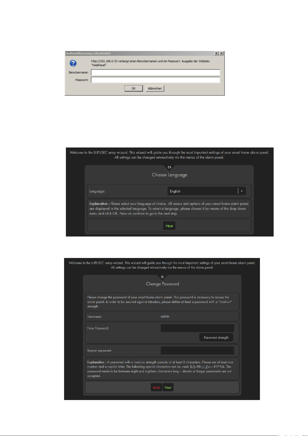
4. The login window opens:
Enter the following default access data upon the initial access:
User name: admin
Password: admin1234
5. The installation wizard
The installation wizard guides you through the initial set-up of the alarm panel.
a) Choose a language
b) For reasons of security, you will need to change the password. It is not possible
to use the alarm panel with the standard password! Make sure to remember
the new password and be aware of major and minor letters.
29
Page 30
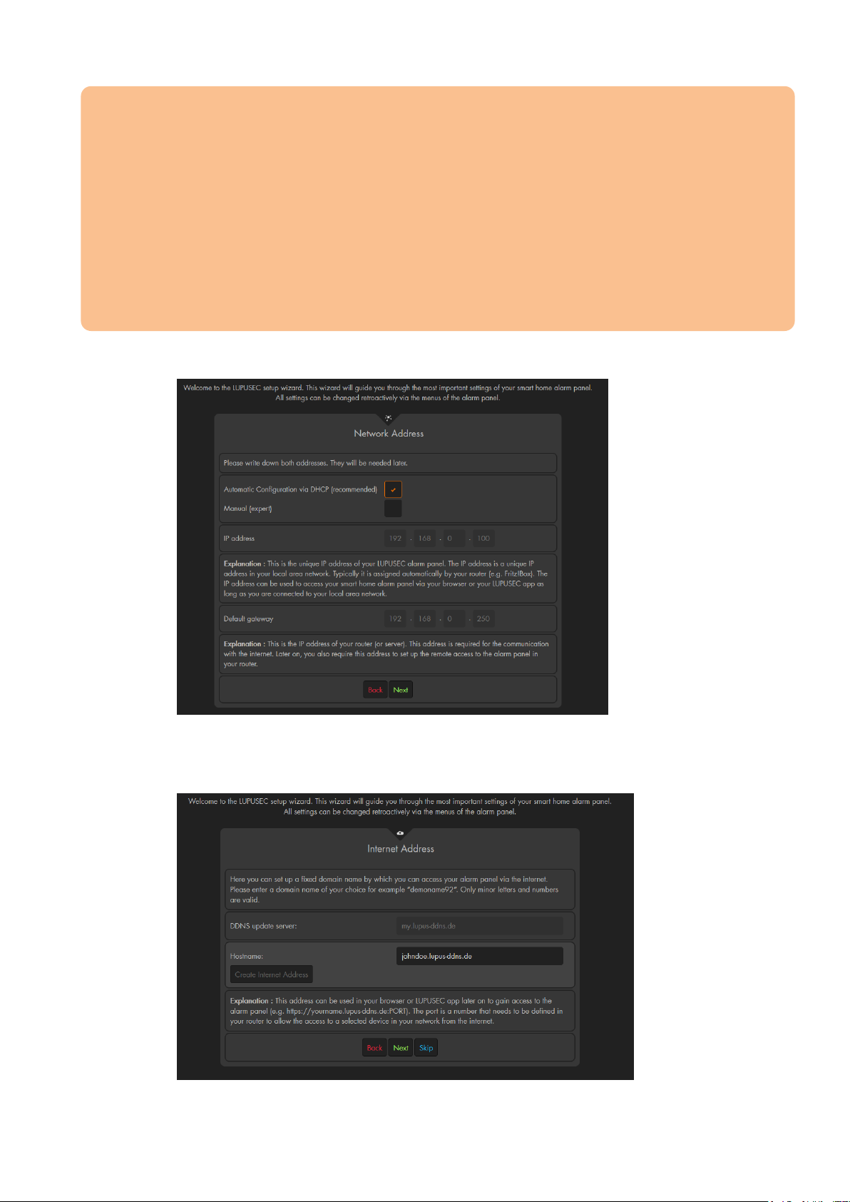
Important
The password needs to be at least 8 characters long (ASCII Code 33-126). A weak
password is not accepted (it needs to be at least medium).
o Blanks are not allowed!
The username may consist of major and minor letters and numbers.
o The users “expert” and “user” have less access rights and are deactivated
by default. You can find more information in the chapter “System”
“Access”
o The username has to be at least 5 characters long and may not be longer
than 20 characters.
c) Now you can change the network settings of the alarm panel. We advice you
to use DHCP.
d) You can now create a DDNS address for the access via the internet (IPv4
required). The DDNS address is created by the alarm panel – you do not need
any username or password for the DDNS.
e) A note about the further requirements for a remote access are displayed. You
30
Page 31
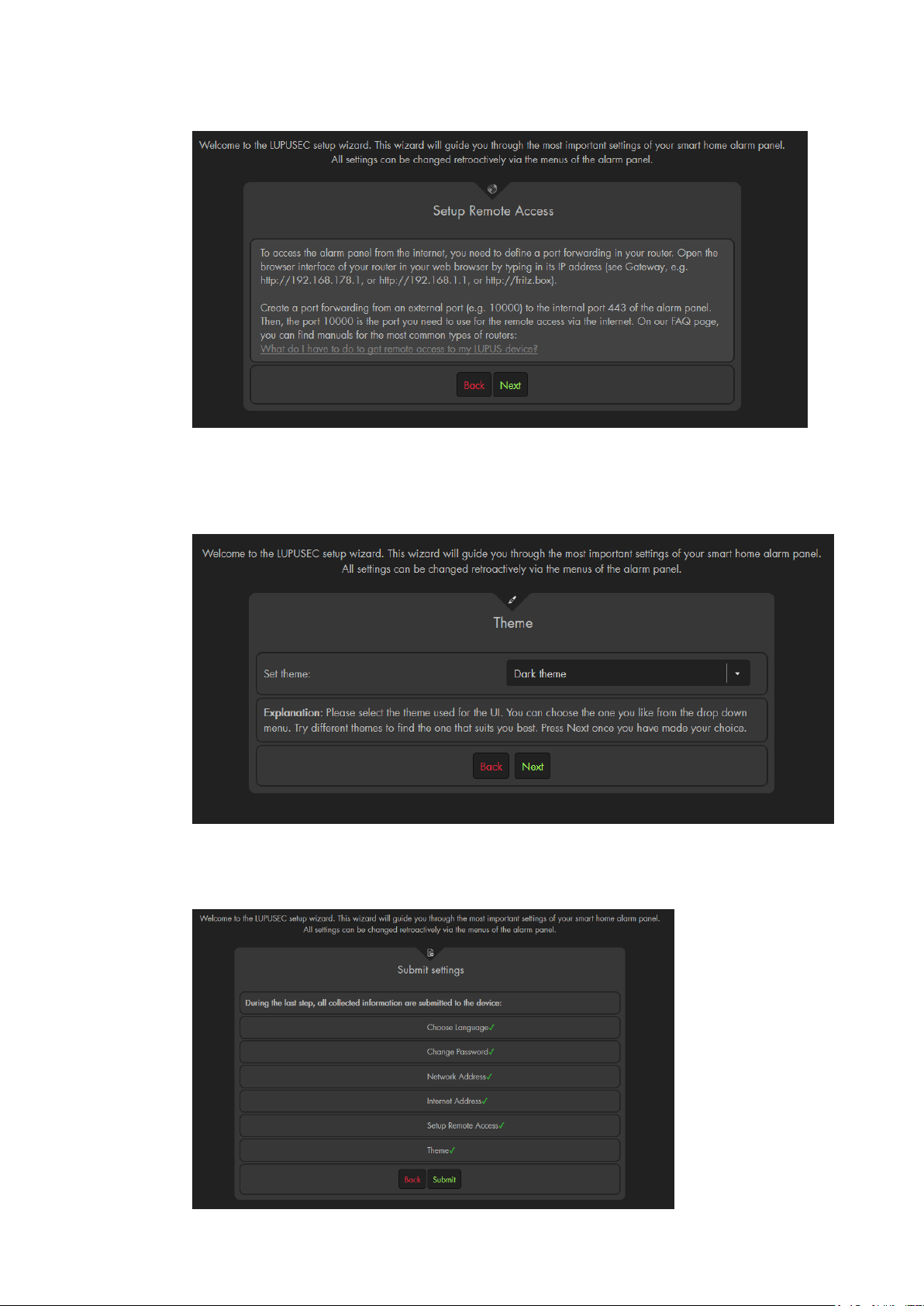
can find more information in the chapter “remote access via the internet”.
f) Now you can choose between a dark and a light theme for the user interface.
The default option is the dark theme and the manual only features the dark
theme (the only difference of the themes is the colour – all options and menus
are identical).
You can change the theme later in the menu “Alarm system” “Settings”
“Display”.
g) In the last step, all settings are transmitted to the alarm panel.
31
Page 32

Please note:
We recommend using Mozilla Firefox for web access to the alarm panel, which is
available on the provided CD.
You can save the IP address of the alarm panel e.g. in the list of favorites or
bookmarks of your browser to access the user interface of the alarm panel in an
easier and quicker way. Access via the IP finder is not required anymore.
32
Page 33
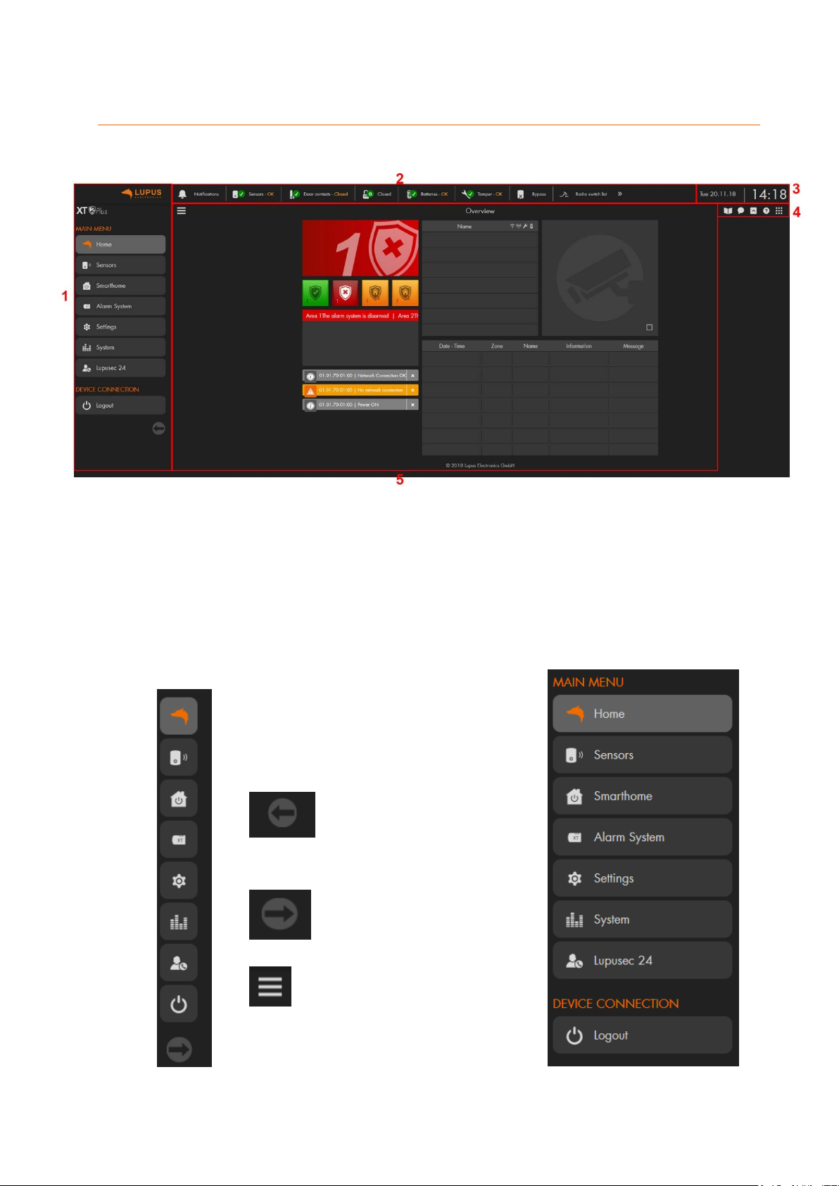
User interface of the alarm panel
The arrow headed to the
left allows you to minimize
the menu.
The arrow headed to the
right allows you to
maximize the menu.
This button allows you to
completely hide or show the
menu.
The user interface consists of 5 elements:
1. Main menu
The main menu contain the sub-menus to control the alarm panel and consists
of: “Home”, “Sensors”, “Smarthome”, “Alarm system”, “Settings”, “System”,
“LUPUSEC 24”, and “Logout”. You can change the menu by left clicking on the
menu you want to access. Depending on the menu you choose, additional sub-
menus appear. The menu you have currently open is highlighted.
33
Page 34
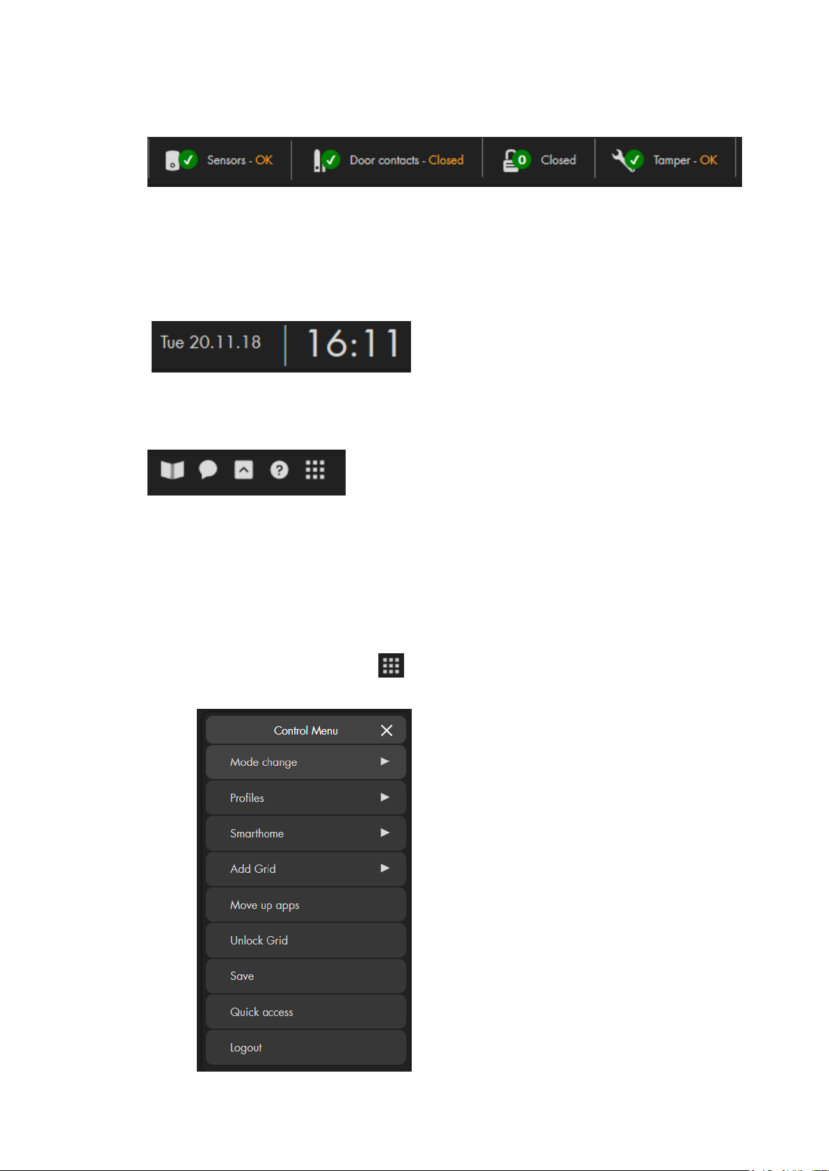
2. Quick access menu
The quick access menu allows you to display important information about the
status of the alarm panel. By pressing on an item, you receive additional
information. You can define which items and in which order items are displayed in
this menu.
3. Date and time
The top right corner shows the current time and the date.
4. Help and control menus
The book icons opens the latest manual as a PDF file (internet connection
required).
The speech bubble opens the FAQs (frequently asked questions) on our
website.
The arrow icon allows you to hide or show the quick access menu.
The question mark opens starts the guide that explains the GRID interface
and the main menus. This symbol is only shown in the “Home” menu.
The icon with the 9 dots opens the control menu. This menu can also
be accessed by right clicking in any other menu.
Please note:
In the “Home” menu, the control menu
offers you additional options for the GRID
interface (the “Home” menu): “Profiles”,”
Add Grid”, “Move up apps”, “Unlock grid”,
and “Save”. These options are explained in
the chapter “Home menu (GRID)
configuration”.
34
Page 35
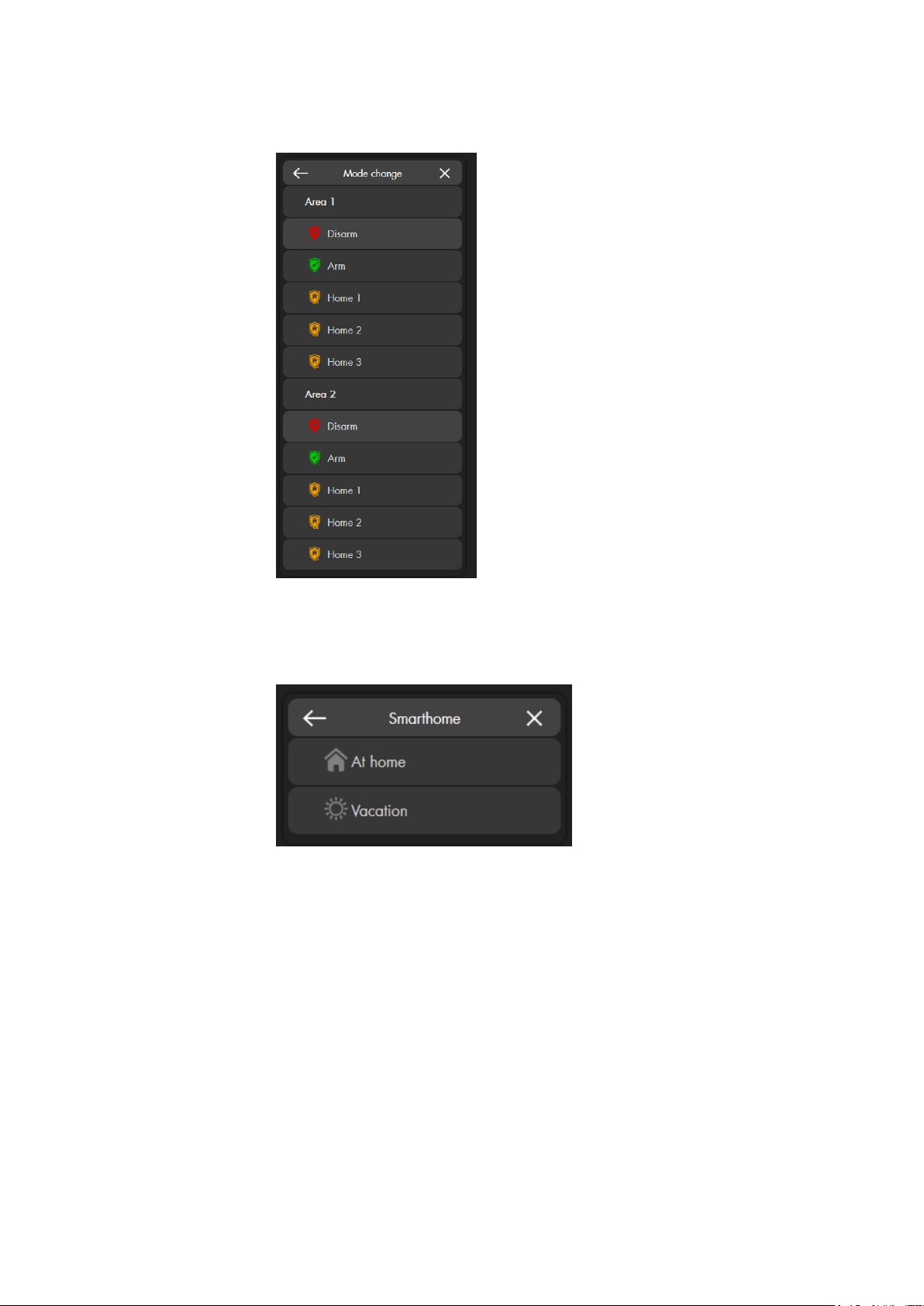
o Mode change
This menu allows you to change the mode (disarm, arm, home 1-3)
of both areas of the alarm panel. The current mode is highlighted.
o Smarthome
If you have created a profile in the menu “Smarthome”
“Automation” “Profile”, you can change the Smarthome profile
directly via this option.
35
Page 36
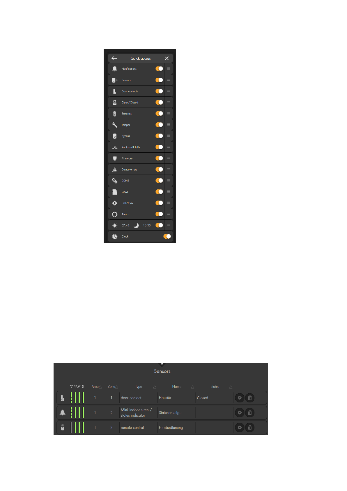
o Quick access
This menu allows you to define which information is shown in the
quick access menu (2).
You can change the order of the items via drag&drop (holding the
left mouse button and moving the item).
o Logout
Allows you logout of the user interface of the alarm panel.
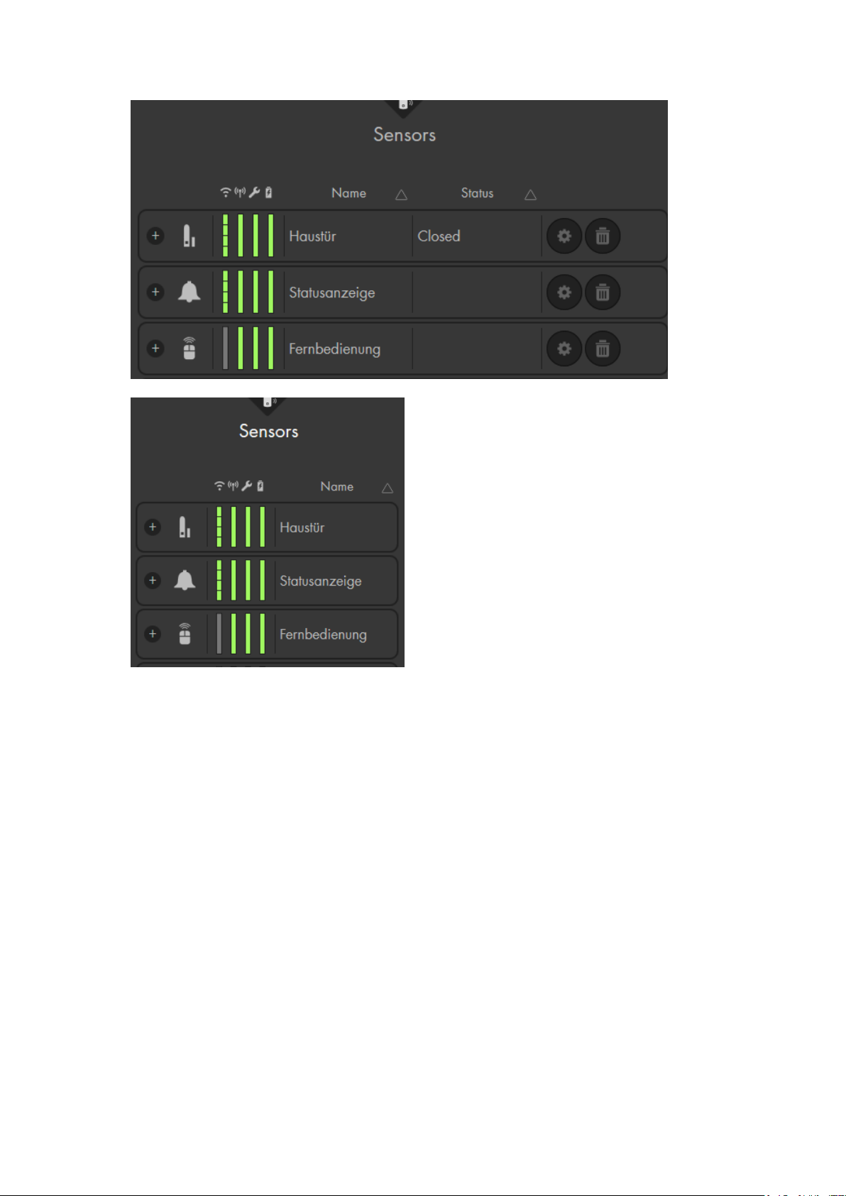
5. Configuration menu
Use this menu to make settings and configurations of the selected sub-menu. The
content changes according to the selected menu (e.g. the menu “list” contains the
“sensor list” and “alarm overview”.
Example: Sensor list:
36
Page 37
37
Page 38
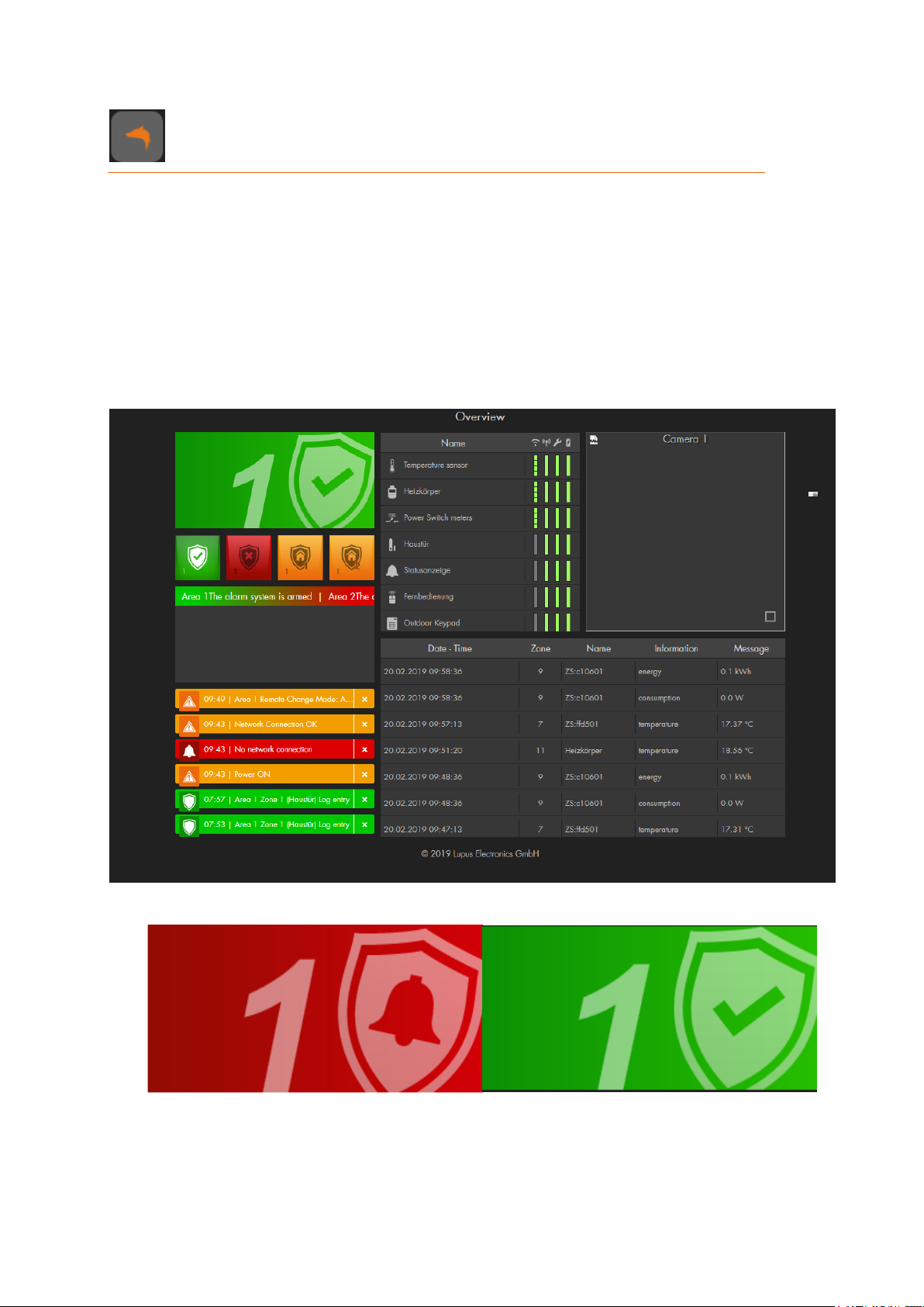
Home menu
1
2 a-d
3
4
5
6
7
The home menu features the GRID interface of your alarm panel. Use the LUPUS GRID
to personalize the user interface of your XT alarm panel in your browser. You define which
indication and information, which functions, and which switches and buttons you want to
display.
There are as many options as there are individual needs.
Configure the grid as follows:
Standard configuration
This is the default GRID interface of your alarm panel. It consists of ten apps:
1. Status indicator app
This app shows only the status of the alarm system, currently of area 1. It is merely
a display function, not an interactive click function. The next paragraph explains how
to change the status.
38
Page 39
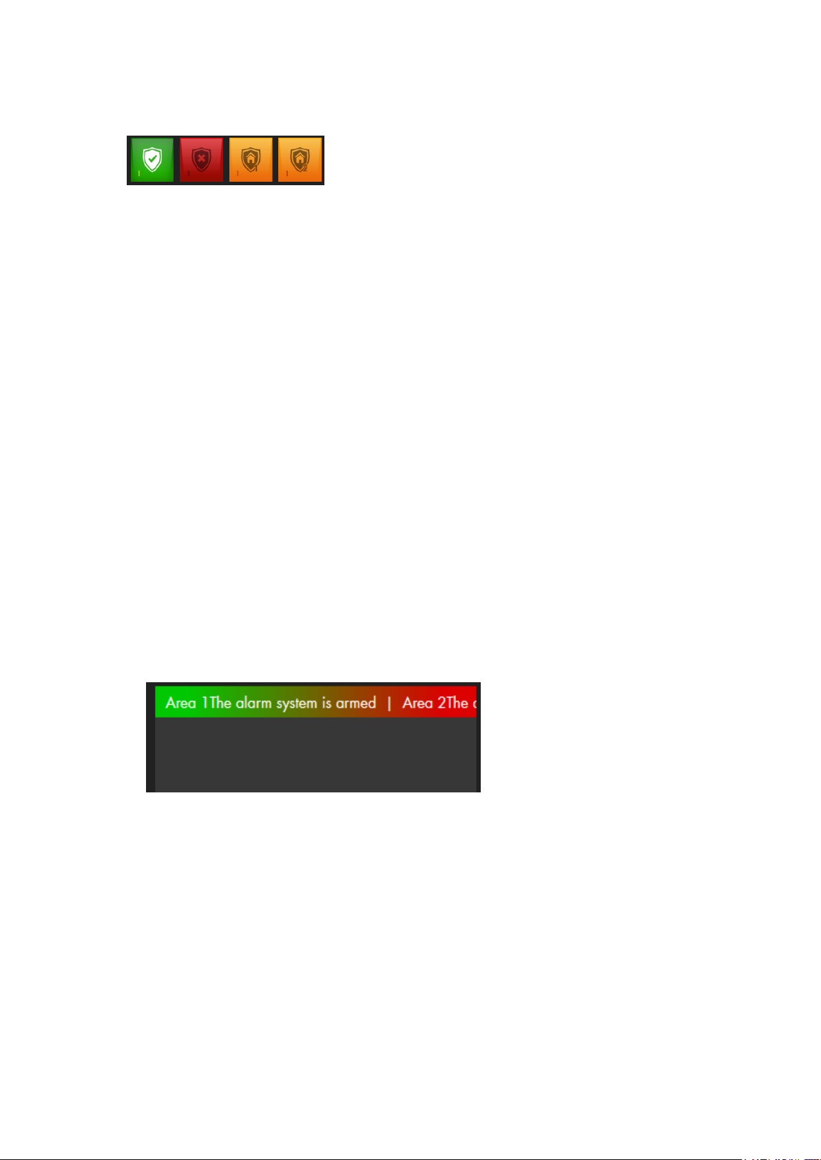
a b c
d
2. Alarm mode app
Section 2 shows altogether four alarm mode symbols. Click to set the alarm panel to
arm, disarm, or one of the home modes. The section consists of altogether four alarm
mode apps. Each app fulfills its own function and enables the mode set in the app
settings.
a: If the alarm panel is set to “Arm”, it is armed, meaning that each sensor
activation triggers an alarm. The alarm panel sounds a single long notification
tone when you arm it.
b: If the alarm panel is set to “Disarm”, it is disarmed and does typically not trigger
alarms. The alarm panel sounds two short notification tones when you disarm
it.
o There are exceptions (water, medical emergency, fire alarm…) which are
described in more detail in the chapter “Edit sensor”.
o In case of an alarm, you can use the “Disarm” button to end the alarm.
c, d: The Home modes 1-3 (the example only shows two) activate specific alarm
zones within the areas. The alarm panel sounds three short notification
tones when you switch to home mode.
Example: If you do not want to trigger an alarm by a motion detector when
someone enters the kitchen at night, set the option “Home 1 response” to “No
response” in the settings of the motion detector to deactivate the sensor in this
mode.
3. System status app
The “System status” app shows the currently most important messages. In the
example above, it shows that area 1 is armed and area 2 is not. Furthermore,
Important problems would be listed in this section. You can ignore an error and the
status (ignored / not ignored) is always listed behind an error.
39
Page 40
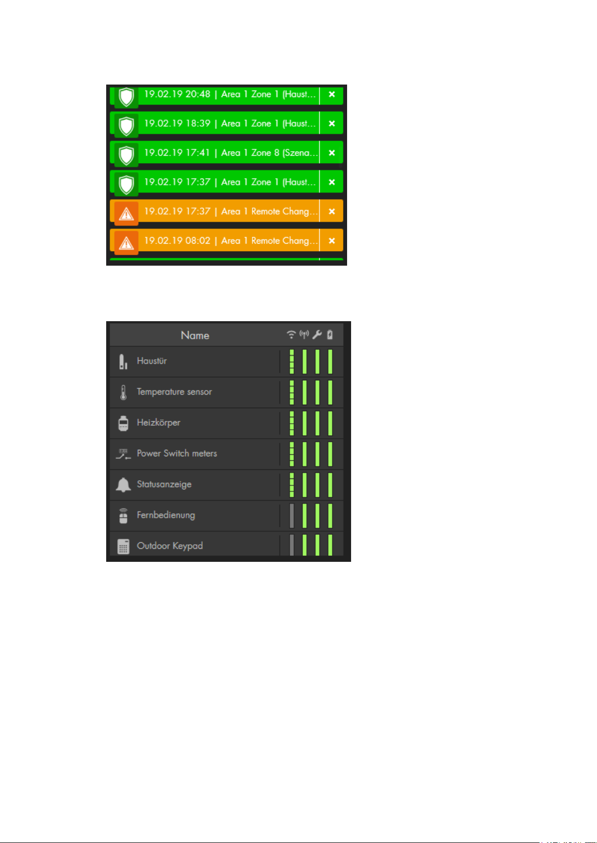
4. Notification app
The notification app displays the important sensor and system messages. You
only see a list of the latest events.
5. Sensor list app
The Sensor list app displays the installed sensors with their icon and name. The
column to the right shows the signal strength of the sensor (“WIFI” symbol), the
status (“radio tower” symbol), the tampering contact (wrench symbol), and the
battery status (battery symbol). The indicators are colour coded, green signals that
everything is OK, red signals that there is a problem.
The amount of information in this app depends upon the selected size. If you
increase the size of this app, the amount of displayed information increases.
40
Page 41
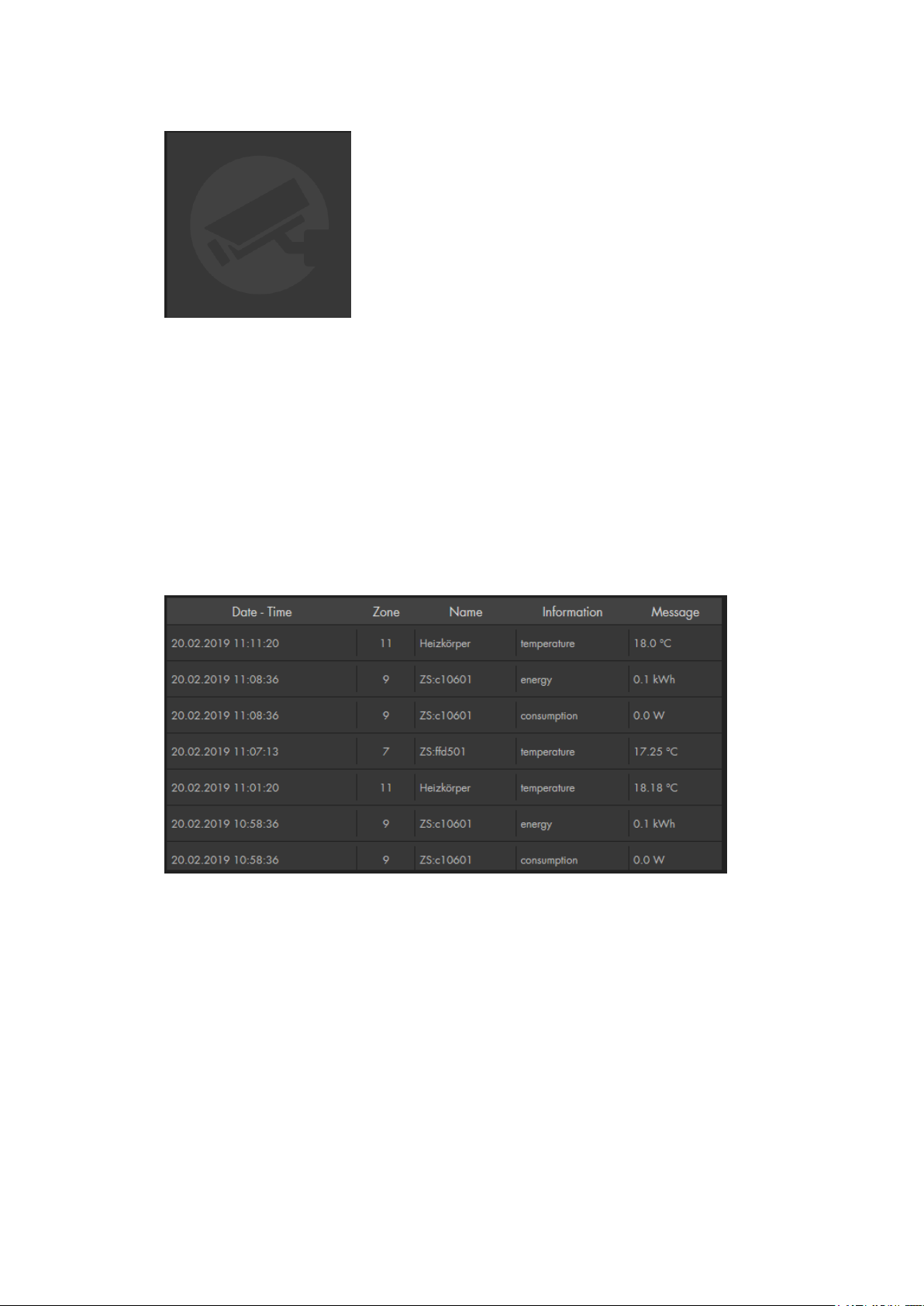
6. Camera app
This app displays the live stream of your cameras or recorders. You need to add
your cameras or recorder in the menu “Smarthome” “Cameras” in order to
display them in the GRID.
You can only add one camera app to the GRID. By pressing on the arrows at the
left and right when moving the mouse over the live stream, you can circle through
all your cameras.
Note:
The PIR network camera can only take pictures in Arm mode, but cannot supply
a live video stream. These screenshots are stored in the menu “Home”
“Capture” “Image events”.
7. Sensor messages app
This app shows the recent sensor messages, e.g. temperature and power
consumption. The amount of information in this app depends upon the selected
size. If you increase the size of this app, the amount of displayed information
increases.
41
Page 42
Configure overview page
The new Grid overview page facilitates the individual representation of information of your
smart home alarm panel. There is a specific app for each function and each sensor that
can be adjusted dynamically in size and, thus, its extent of information.
Large
Medium
Small
Click on the symbol on the top right to open the overview settings. The chapter „User
interface of the alarm panel“ above, described already the functions of the “mode
change”, “Smarthome”, “Quick access”, and “Log out” options.
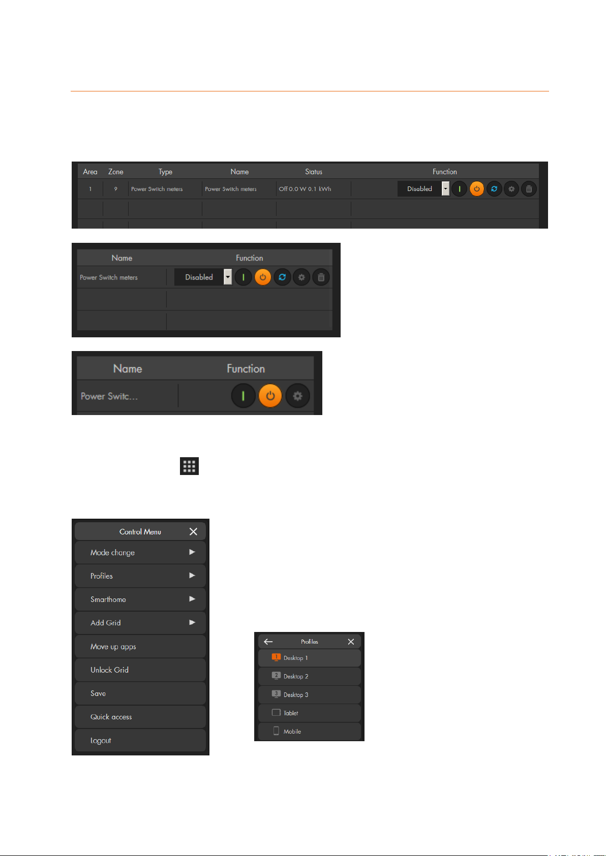
Profiles:
Use “Profiles” to open and configure various different
GRID layouts. The currently active profile is highlighted in
orange. Altogether five grid pages are provided that
cannot be renamed:
42
Page 43
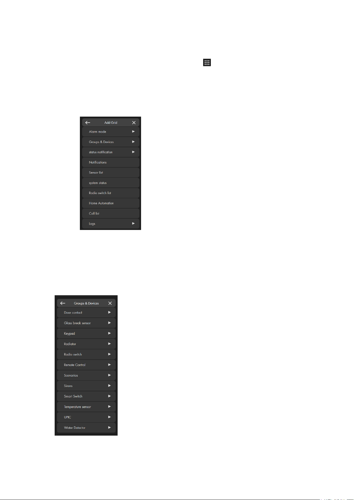
Add Grid
To adjust your overview page, please proceed as follows:
1. Open the “Control menu” (right click or ) and click on „Unlock grid“.
2. The maximum space available for apps is highlighted in grey.
3. You can drag&drop (left mouse button) to sort the apps in your unlocked
GRID.
4. To add new apps, you need to click on “Add Grid” and a list with available
apps appears.
a) Alarm mode
Use this app to change the alarm status of the alarm panel. If you e.g. set up an app
via “Alarm mode” “Area 1” “Arm”, you can arm the alarm system with one click.
b) Groups and devices
Shows a list of the available apps for sensors, groups, or scenarios. Sensors with
similar functions are grouped, because they use the same app.
Please note:
Some of these apps have functions of their own (switches, scenarios, radiator valve
thermostats), while others only display the current status (door contact, motion
43
Page 44

detector, light sensor, smoke detector).
c) Status notification
This app displays the status of the alarm panel.
d) Notification
This app displays all the important sensor and system messages.
e) Sensor list
The Sensor list app displays the installed sensors with their icon and name. The
column to the right shows the signal strength of the sensor (“WIFI” symbol), the
status (“radio tower” symbol), the tampering contact (wrench symbol), and the
battery status (battery symbol). The indicators are colour coded, green signals that
everything is OK, red signals that there is a problem.
The amount of information in this app depends upon the selected size. If you
increase the size of this app, the amount of displayed information increases.
f) System status
This app displays the most important messages for the safe operation of the system,
e.g. alarm status, sensor failures, or other similarly important system messages.
g) Radio switch list
This app displays the integrated wireless power supply devices and relays. You can
use the displayed devices according to the description in the chapter “Smarthome”
“Wireless Plugs” “Wireless plugs list”.
h) Home automation
This app displays all home automation rules that are currently in your active home
automation profile. You can use the play symbol ( ) to trigger the rule manually.
i) Call List
Displays outbound, missed, and inbound telephone calls of your connected Fritz!Box.
j) Logs
You can choose between the available logs that are in the menu “System” “Logs”
(System Messages, Notifications, System events, Reported events, Sensor
messages) and display them in the GRID.
k) Camera
This app opens a live window for the selected camera. The app size is adjustable.
You can only add one camera app to the GRID. If a camera app is already part of
your GIRD layout, “Add Grid” does not offer you to add another one.
A functional button ( ) in the bottom right corner of the app serves to activate the
automatic image cycle of all installed cameras. By pressing on the arrows at the left
and right when moving the mouse over the live stream, you can circle through all your
cameras.
Move up apps
This function moves all apps as far as possible to the top.
Unlock GRID
When you unlock the GRID, you can right click on an app for additional options:
1. Apps
44
Page 45
Allows you to change the selected app into another one.
2. Size
Allows you to change the size of the app. The available sizes depend on the
app you want to change. You can also use the mouse to directly change the
size of the app directly in the GRID.
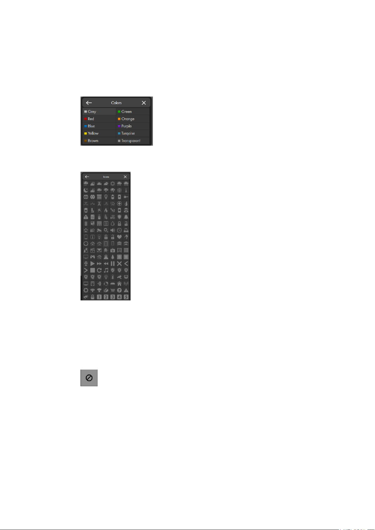
3. Colors
Allows you to change the background color of the app (only available for
“Groups & Devices” apps).
4. Icons
5. Remove app
Lock Grid
Ends the set-up mode to the GRID.
Save
Saves all changes you have made to the GRID. If you do not save, you receive a
warning when you want to open another menu. If you ignore the warning, all
changes to the GRID are reverted.
Allows you to change the symbol of the app (only available for “Groups &
Devices” apps).
Deletes the app.
Please note:
If one of your apps in the GRID belongs to a sensor that has been deleted
from the alarm panel, the GRID displays an error symbol:
To prevent malfunctions of the GRID interface, we advise you to delete
inactive apps.
45
Page 46
Sensors
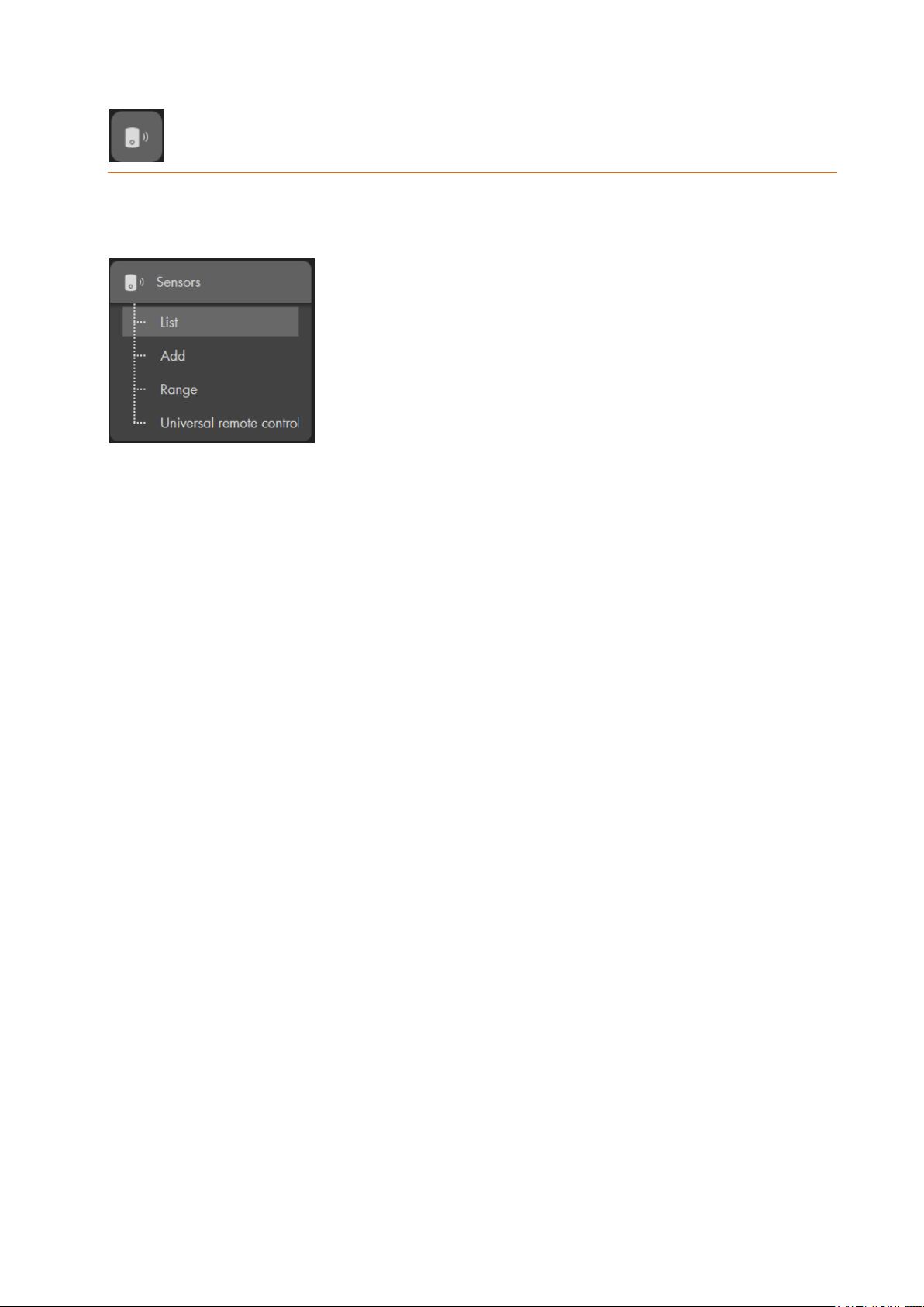
This menu shows the sensor list including all the connected sensors. The submenu “Add”
allows you to integrate new sensors to the alarm panel; “Range” is used to test the signal
strength; “Universal remote control” allows you to set-up your “universal IR controller”.
Note:
All components except wireless relays (item no 12014) and repeaters (item no 12016)
are counted as sensors. The alarm panel features two areas and each area supports up
to 80 sensors. Of the 160 sensors that could be connected, only 40 may be ZigBee
devices and 6 may be “PIR network cameras”. By using a ZigBee repeater you can
enhance the maximal amount of ZigBee devices that you can connect to the alarm panel
(depending on the repeater between 10 and 40 additional ZigBee devices are possible).
The maximal amount of possible sensors (80 per area) is not increased when using a
ZigBee repeater
Additionally, you can connect any number of devices (“wireless relay” item no. 12014 and
“wireless repeater” item no. 12016).
46
Page 47
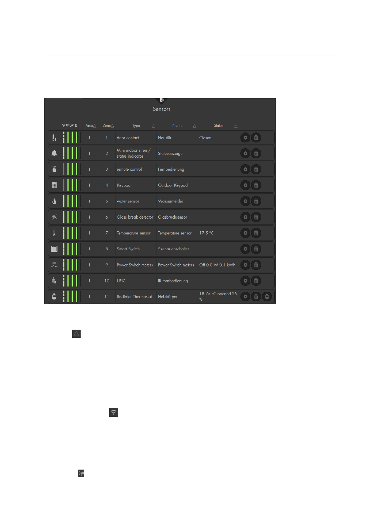
List
The menu “Sensors” “List” offers the “Sensors” in a list, as well as, the “alarm
overview” list.
Sensor list:
In this menu, you can find all sensors that are connected to your alarm panel. You can
change the sorting of the sensor list by means of the sort symbol at the top of each
column:
The list contains all information about the sensors. The four colored bars at the left of
each sensor indicate the signal strength, status, tampering contact, and battery. If you
move your mouse over one of the bars, you receive additional information.
Symbol
Each sensor type has an individual symbol that allows you quickly identify the sensor
type.
Signal strength
The higher the signal strength, the larger the bar is filled. If the signal strength is equal
or less then 2, a wireless repeater should be used. If the bar is red and displayed as
N/A (not available) when you mouse over there is no value currently available. The
signal strength of all sensors is N/A after a reboot of the alarm panel. This is normal –
the next time the sensors is checked (supervision), the test button is pressed, or the
sensor sends out a signal, the status will be displayed.
Status (indicator bar)
Shows the status of the sensor. A green bar indicates that everything is all right. A red
47
Page 48

bar indicates that something is not all right, e.g. the sensor is not working. If the bar
flashes, it indicates that, e.g. a door contact was opened or closed.
Tampering contact
The bar is green as long as the tampering contact of the sensor is closed. As soon as
the tampering contact opens (e.g. if you open the sensor or if someone tampers with
the sensor), a tampering alarm is triggered and the turns red. By default the siren would
only sound if the alarm panel is in arm or home mode. In the menu “Alarm system”
“Settings” “Area settings” “Tamper alarm” you can define if an alarm should also
sound in disarm mode.
Battery
The indicator bar is green as long as the sensor is all right. When the battery runs low,
the indicator bar turns red.
Area
Shows the area, in which the sensor was added. Areas can be armed separately.
Zone
This is a consecutive number provided for each newly added sensor.
Type
Shows the type of sensor, e.g. “Door contact” for a window/ door contact.
Name
You assign this name when you add a new sensor. It is limited to 30 characters.
Status
Shows the status of the sensors. Depending on the type of sensor, the following
statuses are possible:
o Open = open door sensor | Closed = closed door sensor
o Out of order = malfunction / Battery low / out of range
o Tampering contact open
o Temperature indicator in degrees Celsius
o Power consumption in Watt
o Bypass: The sensor has been deactivated by the bypass function and is highlighted
in orange. Please refer to the chapter “Edit Sensor” on the following pages for more
information about the bypass function.
o Blank = no status to report / working as intended
Sensor actions column
In the column to the very right, you can change the settings of the sensor and open the
“Edit sensor” menu ( ).
You can delete a sensor from the alarm panel ( ).
You can enter the thermo control menu of your radiator valve thermostats ( ).
You can take a manual snapshot with your PIR network cameras ( ).
48
Page 49
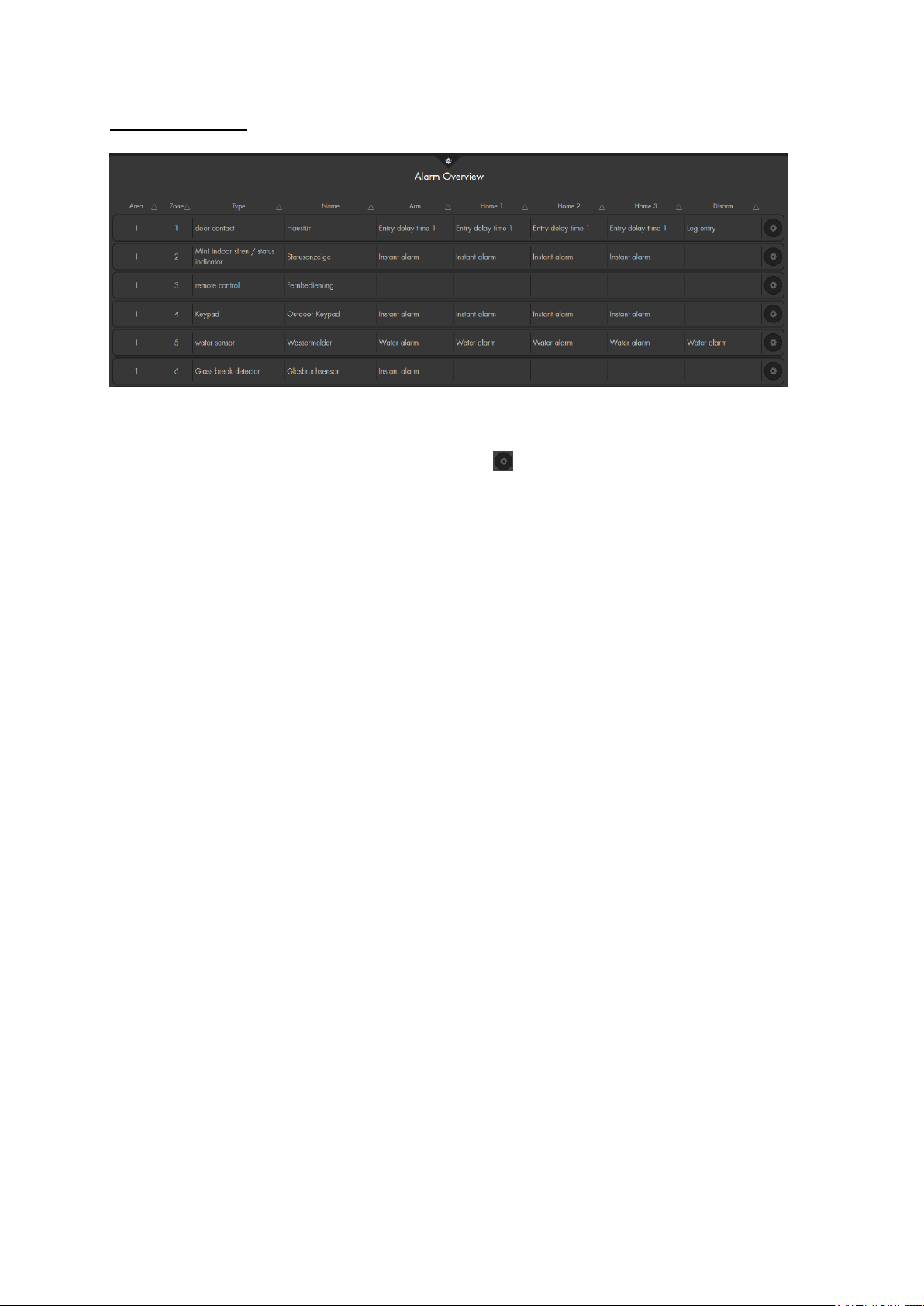
Alarm overview
The Alarm overview displays you at a glance the behaviour of the added sensors in the
respective alarm mode (Arm, Home 1-3, Disarm) of the alarm panel. You can change the
configuration by clicking on the setting symbol to enter the “Edit sensor” menu.
49
Page 50
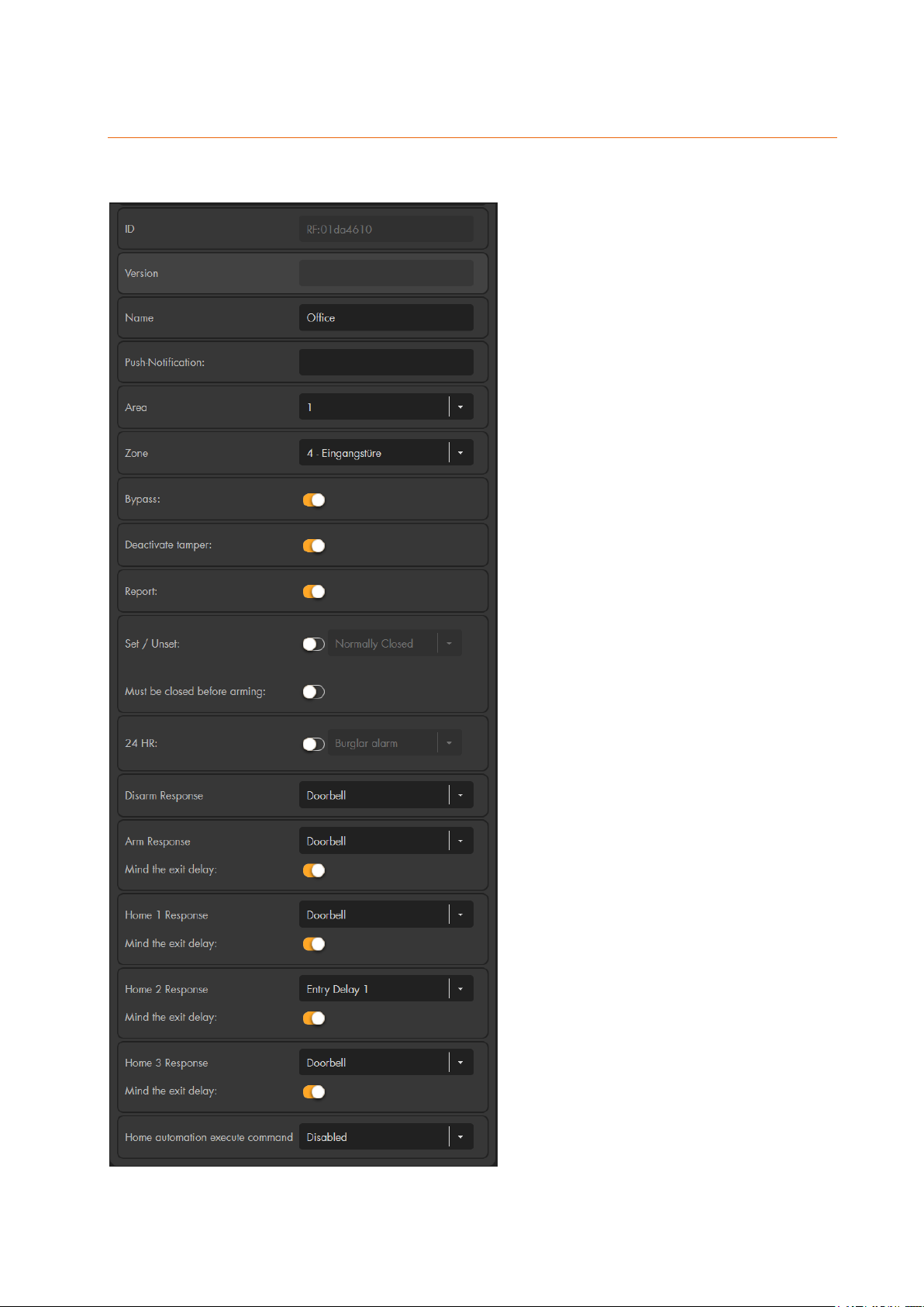
Edit sensor
You can assign different properties and actions to most of the sensors. In case of an
alarm, the sensor reacts according to the set parameters.
Depending on the type of sensor, the
following settings are available:
ID
Shows the sensor-specific ID (not
editable).
Version
Shows the software version (only for
certain sensors)
Name
Assign an individual name of up to 30
characters for the sensor.
Push-Notification
(only door contact, PIR motion
detector, sensor input)
If you have entered a text, a push
notification containing the entered
text is sent to your smartphone by
means of the app ever time the
sensor is triggered (e.g. open/close of
a door contact). The status of the
alarm panel (arm, home, disarm) is
irrelevant in this regard! Only enter a
text in this field if you want to monitor
a certain contact. If you only want to
get notified in case of an alarm, you
need to activate the push notification
in you LUPUS app.
Area
Assign an area to the sensor. The
areas can be armed separately.
Certain sensors (e.g. sirens) require
additional steps in order to change
the area. Please refer to the
corresponding part of the manual to
check if your sensor requires certain
additional steps.
Zone
Assign a zone number to the sensor.
Every zone number may only be
assigned once per area. Each area
has maximally 80 zones.
50
Page 51

Bypass
If a sensor is set to bypass, this sensor will not trigger any alarms (does not apply
to tampering alarm), as long as the bypass is active. This option is only available
for sensors that can trigger an alarm.
Please note:
If a sensor displays an error (e.g. low battery), you can ignore this in the menu
“System” “Status” “Panel” or via the “Quick access” bar “Device errors”.
Deactivate tamper
If this function is active, the sensor will not trigger tampering alarms anymore (by
e-mail, text, siren, or wireless relay). However, a warning is still issued if the alarm
panel is armed (or set to Home mode) until the system error is solved or ignored.
Example:
This function can be important if a sensor/tampering contact got loose during
longer periods of absence and you do not want to receive a message concerning
the open tampering contact every time the sensor status is checked.
Report
If this function is active and you use this sensor to change the mode of the alarm
panel (Set/Unset), you receive a notification. Depending on your set-up, this
notification is send via contact ID to an alarm service centre, e-mail, pushnotification, or SMS. If this option is not activated, you do not receive a notification
if you change the mode of the alarm panel with this sensor.
This option does not influence any other alarm or status notifications!
Set/ Unset
Door contacts and sensor inputs feature this function. By means of this function,
you can automatically arm/ disarm the alarm panel. The alarm panel is
automatically armed or disarmed, depending on whether the contact is closed or
open.
o Normally closed
The sensor is normally closed and arms the alarm panel when opened.
o Normally open
The sensor is normally open and arms the alarm panel when closed.
Please note:
o This function forces the immediate arming/ disarming of the alarm panel,
irrespective of the set delay times or possible system errors (if not set differently in
the menu “Alarm system” “Settings” “Area settings” “Force arm
SET/USNET”)! If you switch this setting to “confirm”, you need to confirm the mode
change again within 10 seconds (e.g. lock the door again).
o If you want to use several wireless lockswitch contacts and arm the alarm panel
only when the last door is closed, you should assign the additional attribute “Must
be closed before arming” to all wireless sensor inputs. Additionally, you need to
change the setting “Force arm SET/USNET” to “confirm” in the menu “Alarm
system” “Settings” “Area settings”.
Must be closed before arming
This function is available for door contacts and sensor inputs. If enabled, it is
impossible to arm the area or set it to home mode, if the door contact with this
option enabled is still open.
Please Note:
o It is necessary to set “Arming with failure” to “Confirm” in the menu “Alarm
system” “Settings” “Area Settings” – otherwise this function does not
work.
o Home automation rules and scenarios can arm the alarm panel irrespective
51
Page 52

of this setting.
24 HR
If this function is active, the set alarm is triggered irrespective of the alarm mode
of the alarm panel, when the sensor is activated.
Disarm / Arm / Home 1 / Home 2 / Home 3 response
Set how the alarm panel reacts if a sensor is triggered in the different alarm modes
o No response
The alarm panel does not react at all, when the sensor is triggered.
o Entry delay 1 / 2
The alarm panel starts the entry delay 1 or 2 if the sensor is triggered. If the
alarm panel is armed or in home mode and a sensor with the property “Entry
delay 1 / 2” is triggered, you can disarm the system within the pre-set time
(see “Alarm system” “Settings” “Area settings” “Entering delay time
1 / 2 ”).
o Mind the exit delay
If this function is active, the sensor will not react during the exit delay
time of the selected mode (Arm, Home 1-3). This function is required
if you want to leave your home without triggering the alarm of a
sensor during the exit delay!
Additionally, if this function is activated, the alarm panel will not
display an error if you change the mode while this sensor is open.
If you have activated “must be closed before arming”, you will still
receive an error if the sensor is open.
o Doorbell
The alarm panel sounds a door bell when the sensor is triggered.
Additionally, the outdoor siren V2 can also sound this doorbell sound (see
siren settings).
o Log entry
There is no notification, but only a log file entry in the alarm panel that the
sensor was activated.
o Log entry (save images)
There is no notification, but only a log file entry in the alarm panel that the
sensor was activated and a snapshot of a PIR network camera is taken.
The snapshot is saved in “Smarthome” “Capture” “Image events”. Be
aware, that this will result in a higher power consumption of your PIR
network camera.
o Burglar alarm Follow
A zone with this property does not trigger the alarm if an entry delay (of
another sensor) was started before. An immediate alarm is triggered if the
entry delay was not activated before.
Example:
Use this sensor property e.g. for a motion detector in the entrance area,
which is directed at the entrance door (equipped with a door contact with
the setting entry delay). Usually, no alarm is triggered, as the premises are
entered through the entrance door. If a burglar accesses the premises
otherwise, the alarm is triggered immediately when he passes this motion
detector.
o Burglar alarm Instant
The sensor triggers the alarm immediately.
o Silent alarm
If a sensor with this setting is triggered, the sirens do not sound an alarm,
52
Page 53
but sends a notification according to your “Alarm system” “Report”
settings.
o Intruder alarm silent
If a sensor with this setting is triggered, the sirens do not sound an alarm,
but sends a notification according to your “Alarm system” “Report”
settings.
Execute home automation command
If the sensor changes its state, one of 16 home automation rules or scenarios can
be performed, which are defined in the Automation menu (“Smarthome”
“Automation” or “Smarthome” “Scenarios”).
All areas (sirens only)
o Older siren versions with DIP switches: If you want to assign an external
siren to both areas, make sure that switch SW1 of the respective siren is
set to ON! Then enable this option. Afterwards, make sure to set switch
SW1 back to OFF.
o Newer siren version without DIP switches:
Press the learn button of the siren.
LED 1 & 3 of the outdoor siren V2 light up. The indoor siren emits a
brief confirmation sound
Check “all areas” and click on “OK”
The outdoor siren V2 sounds a confirmation signal, LED 2 flashes
briefly. The indoor siren emits a confirmation beep.
Current measurement (only wireless power supply devices / relays)
This option allows you to display the power consumption of a power supply
device or relay in the GRID interface.
Deactivated: Activated:
Trigger mode (only power supply devices like in-wall relays and, light switches)
Activates the trigger mode of the selected devices, which is available in the
menu “Smarthome” “Wireless plugs” “Wireless plugs list”. If this function is
enabled, the device is activated briefly and then deactivated again.
Always on (only power supply devices)
If you want to activate a wireless power supply device or in-wall relay irrespective
of the alarm mode of the alarm panel, you can activate this setting. Afterwards,
you once need to activate the PSS device manually. Afterwards, you cannot
switch this off anymore.
Emergency button (only medical emergency controller + panic button)
Allows you to set what kind of alarm is triggered or which automation rule is
performed, when the sensor’s alarm button is pressed.
53
Page 54
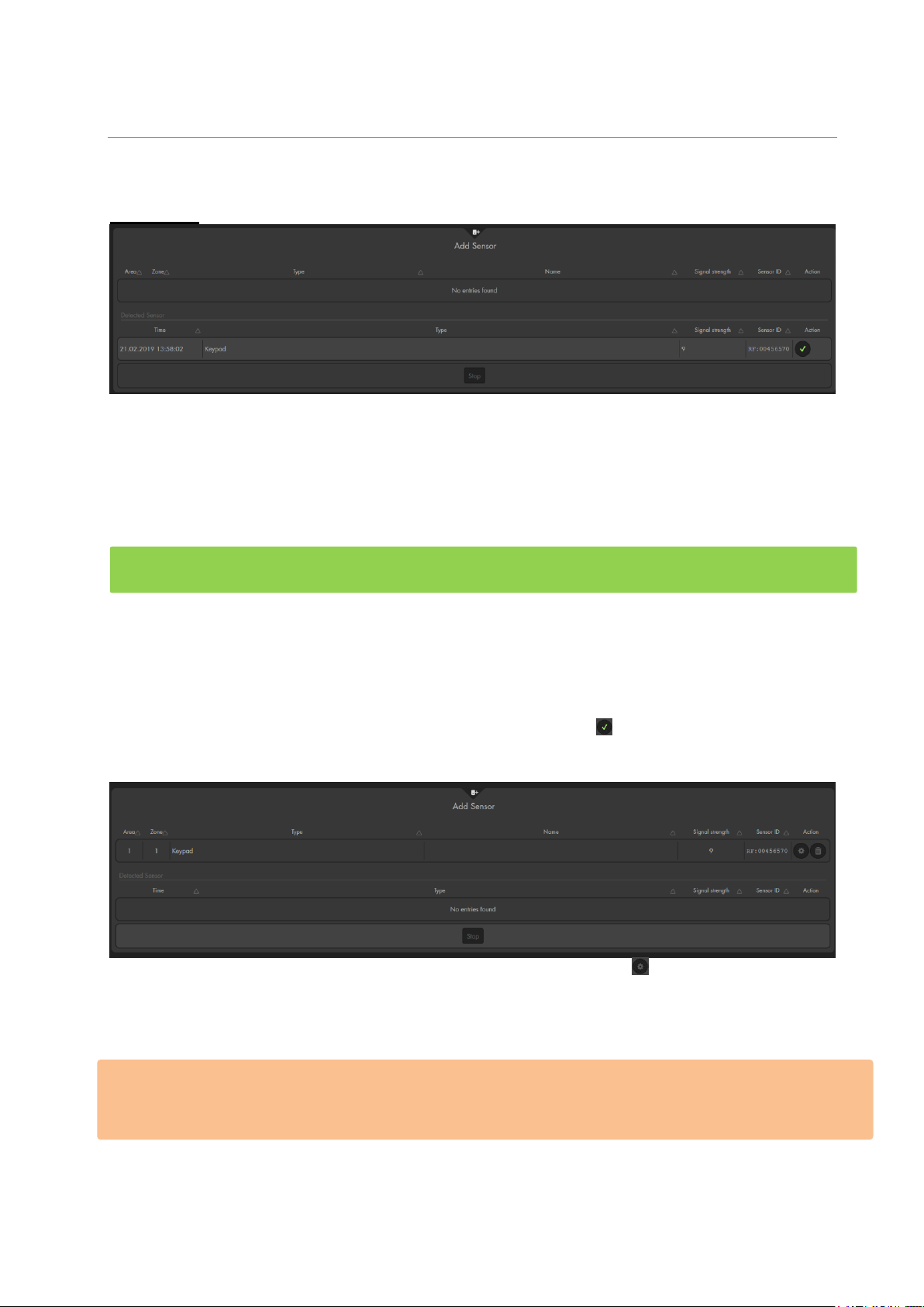
Add
In the menu “Add,” you can add sensors to the alarm panel.
Add sensor
Click on “Start” at the bottom of the menu to activate the learn mode (the LEDs or Area 1
and 2 begin to flash green). Then begin the adding process of your sensor.
Please note:
In the manual of your sensor, you find a step-by-step guide that explains
how this sensor is added. For most sensors, you need to press a certain
button for a specific amount of time.
Older XT2 alarm panels (not Plus version), the area 1 LED flashes green
and the area 2 LED flashes red while in add or range mode.
After a sensor was found, it is listed in the table below “detected sensors”. It also displays
the time when the sensor was found. This can be important if you add multiple sensors
of the same type. Additionally, the type of the sensor, the signal strength and the unique
sensor ID is listed.
You can add the sensor to the alarm panel by clicking on at the right. The sensor is
added to the alarm panel, the alarm panel emits a notification sound, and the sensor is
moved to the up into a different table.
You can assign properties to the added sensor by pressing on . This opens the menu
“Edit sensor” explained in the previous chapter.
You can stop the add mode by clicking on “stop”. After five minutes, the add mode is
deactivated automatically.
Please note:
We advise you to add all sensors before you install them. The sensors stay added when
you open them or remove the batteries.
54
Page 55
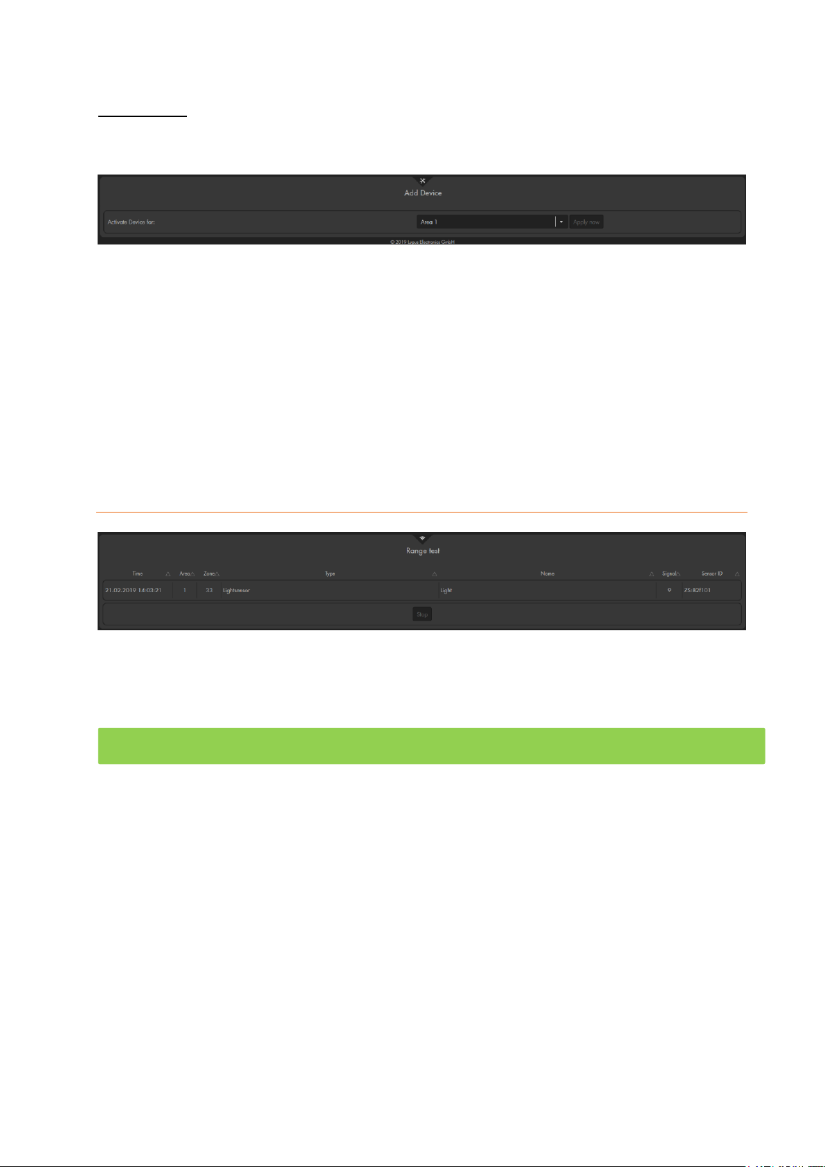
Add device
In this menu, you can add devices to the alarm panel. Devices are wireless repeaters
(item no. 12016) and wireless relays (item no 12014).
Select area 1 or 2 from the drop-down menu next to “Activate device for”, to define the
area to which a device should be added (both areas is not possible). Activate the add
mode of the device and click on “Apply now” to add the device to the alarm panel.
You find step-by-step guides to add the wireless repeater and wireless relay in the
corresponding manuals. If the device was added successfully, the alarm panel confirms
this by means of a short confirmation sound.
You can add any number of devices to the alarm panel.
Range
You can use the “range” function to check the signal strength of any added sensor at its
place of installation.
Click on “start” to start the range test mode (the LEDs of area 1 + 2 flash green).
o Older XT2 alarm panels (not Plus version), the area 1 LED flashes green
and the area 2 LED flashes red while in add or range mode.
Take the sensor to the designated point of installation.
Press the Test button of the sensor for a certain time (see sensor descriptions) to
start the sensor learn mode.
If the alarm panel detects the sensor, it will inform you with a notification sound.
The “Signal strength” in the “Range” menu shows the reception quality.
A signal strength of 9 is the best possible value and a signal strength of 1 the worst
possible. To ensure a loss-free alarm signaling, this value should be at least 3.
If a sensor loses the connection to the alarm panel frequently, you should use a
repeater.
You can find a chart with the compatibility of the various sensors and the possible
repeaters in the chapter “overview of sensor compatibility” and in the FAQs on our
homepage.
End the range test mode by clicking on “stop”.
55
Page 56
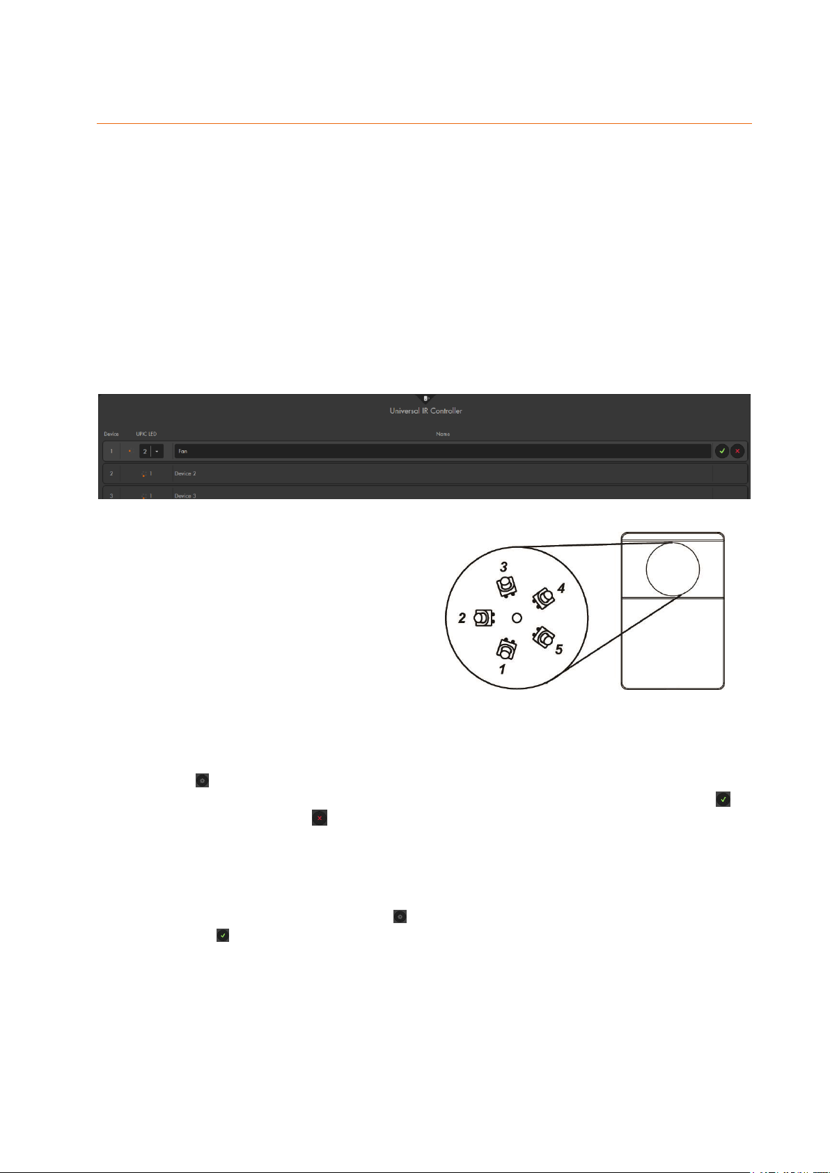
Universal remote control
Via the menu “Sensors” “Universal remote control”, you can operate a connected
universal IR controller. The universal IR controller was developed to control infrared-
controllable appliances automatically and manually. The universal IR controller can learn
IR signals and repeat them. After the IR signals have been learned, you can control the
corresponding device them via the LUPUS alarm panel without using the related remote
control.
As long as you do not have a universal IR controller added to the alarm panel, this
menu displays no options.
For clarity reasons, you can name the controlled appliance yourself and assign an
LED of the universal IR controller to the appliance.
The IR transmitter is equipped with six
LEDs, sending the IR signal. One
LED is in the center, the other five are
arranged in a circle. The five outer
LEDs have a 45° offset.
Each LED transmits the signal in a
cone-shaped way emanated from the
position of the LED. The LED in the
middle always transmits the signal.
The surrounding LEDs transmit the signal depending on the selection in the
LUPUS menu. The LED facing the appliance should be selected for the
appliance when assigning them.
In the example, appliance 1 is a fan installed below the universal IR controller.
Press to open the labeling of the appliance, select LED 1 (located at the bottom
of the universal IR controller LEDs) and name the appliance 1 “Fan”. Press to
apply the input, press to neglect the input.
You can label the signals learned before by the appliances via “Learn and test IR
signals” (see manual of universal IR controller) for more clarity. To do so, click on
the appliance, in the example “Fan”. A selection of functions of the appliance
opens. Then press the button to assign a name and save the name by
pressing .
56
Page 57
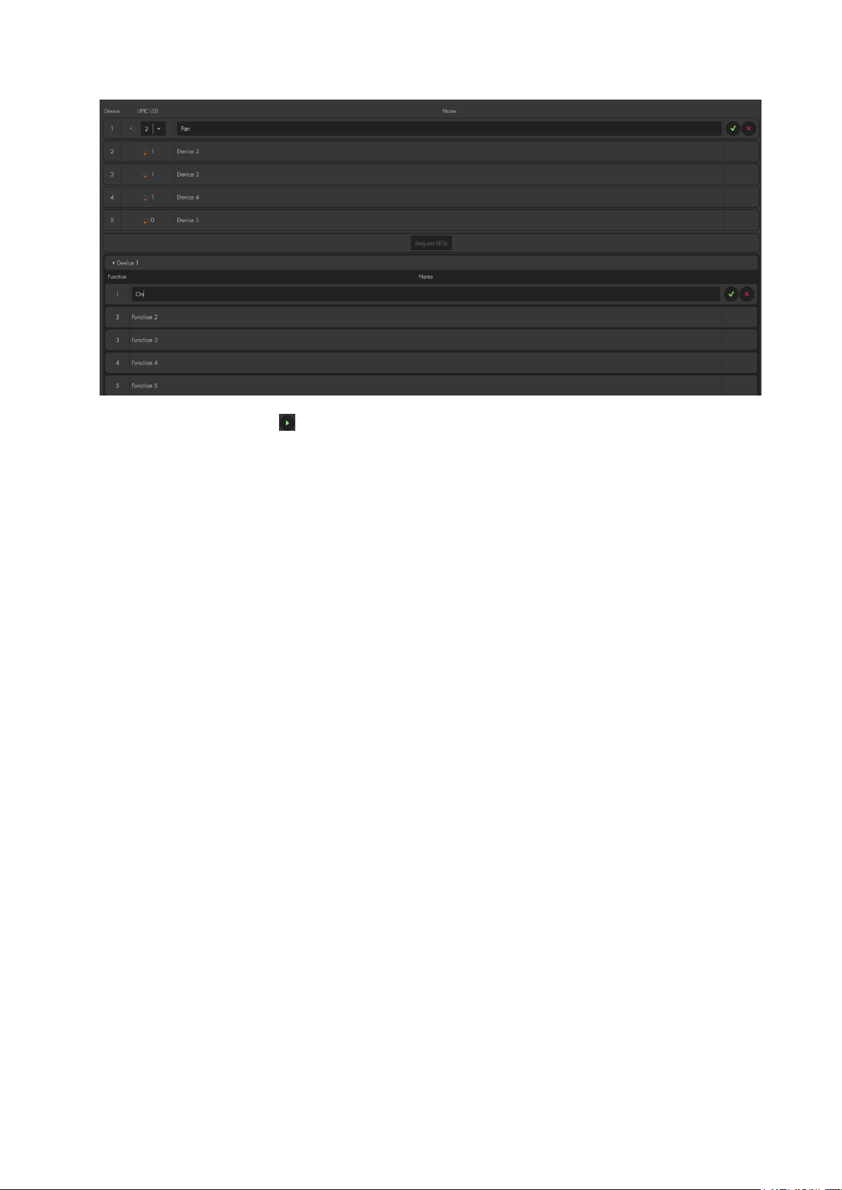
Press the button to repeat (send out) the saved signal, e.g. to switch the fan
on or off.
Five appliances with eight functions (signals) respectively can be programmed for
each universal IR controller.
57
Page 58
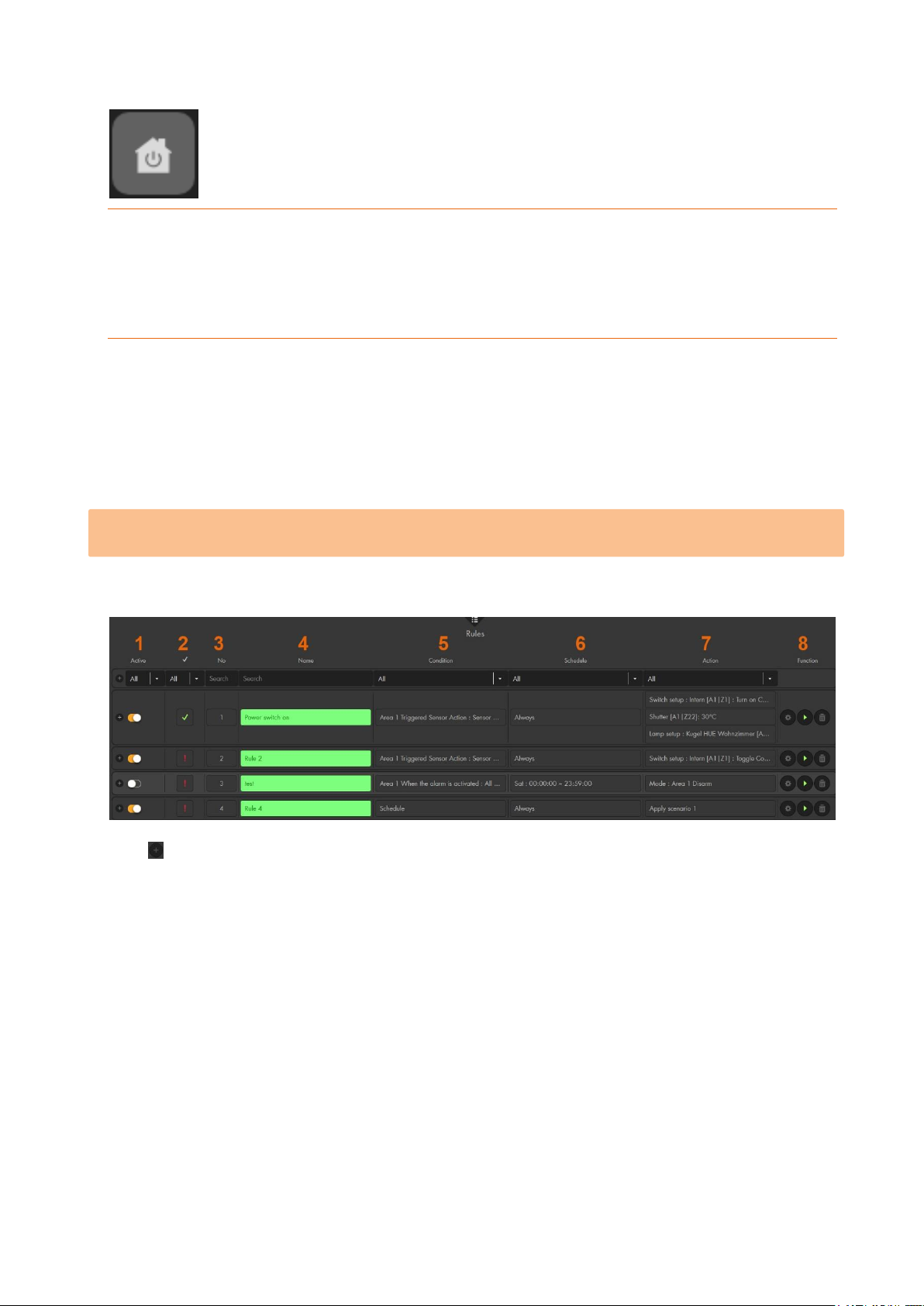
Smart home menu
In the Smart home menu, consists of the sub-menus “Automation”, “Wireless Plugs”,
“Cameras”, “Capture”, ”power consumption”, “temperature history”, and “Scenarios”.
Automation
The Home Automation menu allows the creation of up to 100 automation rules, to assign
them to up to ten groups, and have them executed in up to five profiles.
In the Automation menu, you can set up automations so that e.g. the alarm panel is
automatically armed or disarmed at a certain time when the bedroom is entered. You can
also control any consumer (device) via wireless power supply devices or relays
depending on temperature or other conditions.
Please note: The following chapter “Examples” explains some common home
automations and how they function.
Rules
Lists all rules in a table:
Use to add new rules.
Already created rules can be sorted by means of the title of each column or the
corresponding drop-down menus.
1. Active: Use the checkbox in front to activate or deactivate the rule (by default
always on).
2. Effective execution
Green checkmark: Rule is active and will be performed if the condition is met.
Red exclamation mark: Rule cannot be performed. Refer to “Profiles” for details in
this regard.
3. Nr.: A number is assigned to every rule (the first free number is chosen automatically).
You can change the number later on be means of the drop-down menu (1-100).
4. Name: You can assign a name of maximally 31 characters to a rule. Active rules are
highlighted in green, inactive rules in grey.
58
Page 59
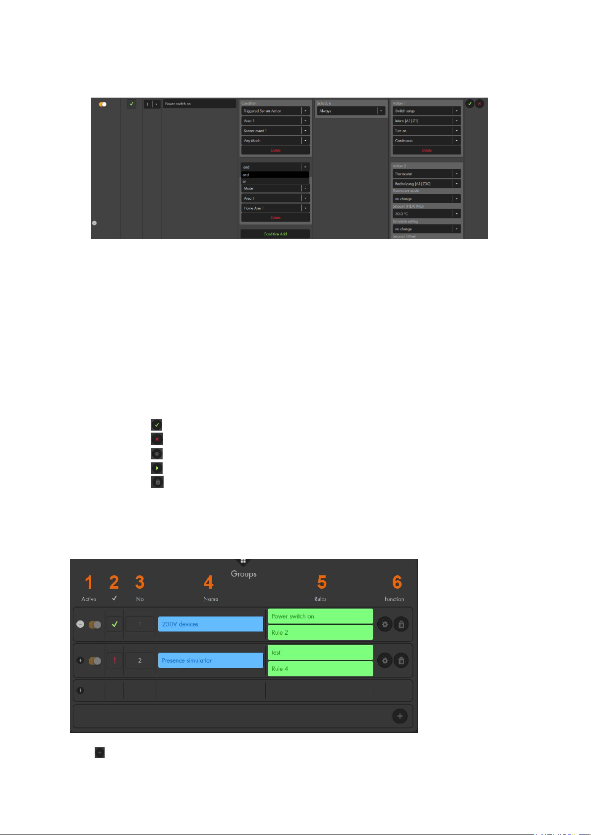
5. Condition: Shows which condition triggers the rule. Each rule can consist up to ten
conditions which can be connected via “and” or “or”.
If you connect two or more rules via “and”, all the conditions need to be met in
order to trigger the home automation rule.
An “or” condition (alongside other “and” conditions) is an alternative condition
to trigger this home automation rule.
6. Schedule: Define a schedule for the rule. The section “Examples of schedules”
explains this in detail.
7. Action: Specify the action to happen when the condition and schedule are met.
Sample applications are given on the following pages. You can combine up to ten
actions in a single home automation rule. Additional actions are added via “Action
Add” and can be deleted with “Delete”.
8. Functions:
Use to save automations.
Use to cancel any changes.
Use to edit exiting automations.
Use to trigger an automation manually (e.g. to test the automation).
Use to delete an automation.
Groups
This is an optional function to unite rules in groups. Groups are used for clarity, e.g. to
unite certain automations that belong together. However, you do not need to use groups
if you do not want to. In that case, forward to “Profiles”.
Use to add new groups.
59
Page 60
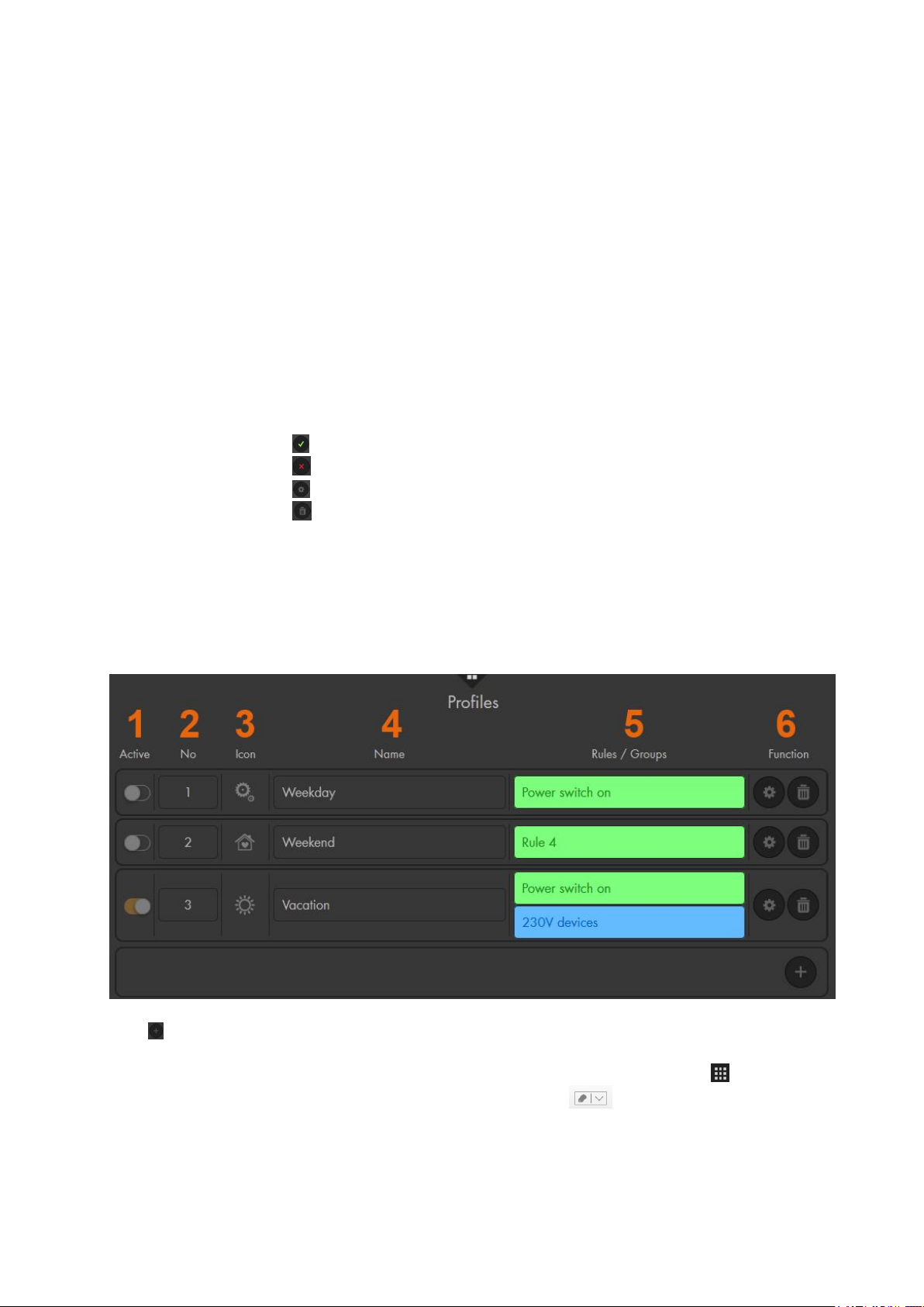
1. Active: Use the checkbox in front to activate or deactivate the group.
2. Effective execution:
Green checkmark: Group is active and will be performed if the
condition is met.
Red exclamation mark: Group cannot be performed. Refer to “Profiles”
for details in this regard.
3. Nr.: A number is assigned to every rule (the first free number is chosen
automatically). You can change the number later on be means of the drop-
down menu (1-10).
4. Name: You can assign a name of maximally 31 characters to a group. Active
groups are highlighted in blue, inactive groups in grey.
5. Rules: Shows the previously defined rules assigned to the group. You can
add others in the drop-down menu or remove rules by pressing the X behind
the name of the rule.
6. Functions:
Use to save automations.
Use to cancel any changes.
Use to edit exiting automations.
Use to delete an automation.
Profiles
Profiles are useful to control rules/automations differently, e.g. when you are on holidays
or at the weekend. For a rule to be executed, it is required, on the one hand, be activated
and, on the other hand, assigned to an active profile. You can create up to five profiles,
however, only one can be active.
Use to add new profiles.
1. Active: Use the activation switch to activate or deactivate the profile. You
can also change the profile by using the “Quick access menu”
“Smarthome”. option of the drop-down menu at the top and select
“Smarthome” “Profile:”
60
Page 61
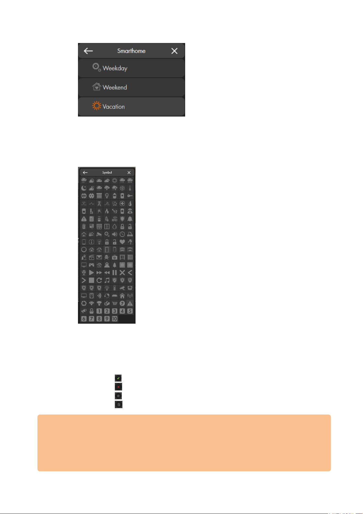
2. Nr.,: A number is assigned to every profile (the first free number is chosen
automatically). You can change the number later on be means of the drop-
down menu (1-5).
3. Symbol: You can assign a symbol to every profile to quickly identify the profile.
4. Name: You can assign a name of maximally 31 characters to a profile.
5. Rules/groups: Shows the previously defined rules and groups which are
assigned to the profile. You can add others in the drop-down menu or remove
rules by clicking on the X behind the name.
6. Functions:
Use to save automations.
Use to cancel any changes.
Use to edit exiting automations.
Use to delete an automation.
Important:
For already set-up rules to be executed, it is required either to add them to a group at
first, which is then added to a profile, or to add them directly to the active profile.
Please make sure that the rules you want to apply are always marked with the green
checkmark in the column “effective execution.” Only then the rule is active if the
assigned profile is active as well.
61
Page 62

Home Automation settings
In the following, we explain the various options of the home automation menu in detail.
In order to create a home automation, you need to insert the following information:
Condition – if the condition is met, the home automation is executed.
Schedule – the home automation is only executed if the condition is met at the
defined time.
Action – the home automation action you want to execute when a certain condition
is met at a certain time.
Condition
Schedule
If you select “schedule”, there is no requirement for this automation other than the
set time in the schedule.
When the alarm is activated
This condition allows you to execute a home automation when an alarm is
triggered. You need to define if the alarm has to be triggered in area 1 or area 2
and if the automation is executed only in case of a certain alarm or in case of all
alarms in the selected area.
Triggered sensor action
This condition allows you to execute a home automation when a sensor sends a
status change. In order to use this condition, you need to define, in the settings of
the sensor (“Sensors” “List” “Sensor List” ), that the sensor has to “apply
rule X” in case of a status change. If the sensor sends a status change, the rule X
is applied as well. Additionally, you can define if this rule shall always be applied
or only if the alarm panel is in a certain mode.
Entering delay
This condition allows you to execute a home automation when the entering delay
begins. Additionally, you can define the area and mode of the entering delay.
Leaving delay
This condition allows you to execute a home automation when the leaving delay
begins (when you arm the alarm panel). Additionally, you can define the area and
mode of the leaving delay.
Mode
This condition allows you to execute a home automation if the mode of the alarm
panel is changed. If you select “mode area 1 disarm,” the automation is always
performed when area 1 is switched to disarm.
Temperature between
This condition allows you to specify two values for a certain temperature sensor. If
the temperature is between these values, the home automation is executed.
Temperature above
This condition requires you to select a temperature sensor. If the temperature rises
above the set value, the home automation is executed.
Temperature below
Identical to “temperature above”, however, the home automation is executed when
the temperature is below the set value.
Energy above
This condition allows you to define a wireless power supply device or relay with
62
Page 63

power meter and to execute a home automation if the power consumption of this
device is above the set value.
Energy below
Identical to “energy above”, however, the home automation is executed when the
energy consumption is below the set value.
Humidity above
This condition is identical to “temperature above,” however, the home automation
is executed if the humidity is above the set value.
Humidity below
This condition is identical to “temperature below,” however, the home automation
is executed if the humidity is below the set value.
Door Lock
You can use your connected Nuki lock to trigger an automation when the door is
“locked” or “unlocked”. If you connect additional conditions via “and” to this
condition, you can define that a automation is only performed when your door is
“locked” or “unlocked”.
(To connect a Nuki lock, please go to chapter “Settings” “Device integration”
“Nuki”).
Lux between
This condition allows you to select a light sensor and to set two lux values. If the
lux value is in between the two specified values, the home automation is executed.
Please refer to the light sensor’s manual for an in detail breakdown of the lux
values.
Lux above
This condition is identical to “temperature above,” however, the home automation
is executed if the lux value is above the set value.
Lux below
This condition is identical to “temperature below,” however, the home automation
is executed if the lux value is below the set value.
Fritz!Box phone call
This condition allows you to use your Fritz!Box as a trigger for a home automation.
To use this function, you need to insert the host IP and port of your Fritz!Box in the
menu “Settings” “Device integration” “Fritz!Box”.
Open since
You can assign a span of time to a door contact. If this door contact is open for the
set time, the action is performed.
No motion since
You can assign a span of time to a motion detector. If during the set span of time,
no motion is detected, the action is performed.
Switch
This condition depends upon the status of a selected wireless plug or relay. If the
selected wireless plug or relay is switched “on” or “off”, the condition is met and
the rule will be executed. If you combine multiple conditions, the current status of
the selected wireless plug or relay (“on” or “off”) is monitored.
Doorcontact
This condition depends upon the status of a door contact. If the selected door
contact is opened or closed, the condition is met and the rule will be executed. If
you combine multiple conditions, the current status (open or closed) of the selected
door contact is monitored.
Random execution
This condition allows you to create a presence simulation. The selected timespan
63
Page 64

in schedule is used to calculate the chance that the automation is triggered in every
minute of this timespan. The 100% chance of execution of the automation is
divided by the minutes in the schedule.
Example
If you set the condition “random execution” and schedule “every day” “20:00 –
20:10”. Per minute, the chance that the automation is triggered is 10%
(100%/10minuntes). If you would have set the schedule to “every day 20:00 –
21:00” the chance would have been divided by 60 minutes (100%/60 minutes),
hence, the chance per minute would be 1.66%.
If you select “guaranteed execution on”, it is guaranteed that the automation is
executed, at the latest, during the last minute of the set schedule interval.
If you select “guaranteed execution off” the chance that the automation is
executed is 100% (calculated as described above 100%/XX minutes), however, it
is not guaranteed that the automation is executed at all.
Please note:
Mathematically, the real chance for the execution of an automation is not identical
for every minute, but reduces over the set time in the schedule, since the
automation could have already been executed before.
Schedule
Always
The automation is always executed when the set condition is met.
Once
Allows you to select a day and a time (Year/Month/Day Hour:Minute) at which the
automation should be executed if the set condition is met.
Every month
Allows you to set a certain day of a month and a time (Day Hour:Minute) at which
a home automation should be executed. If the set condition is met at this day and
time, the automation is executed.
Weekday
Allows you to define timespans for certain weekdays. You can choose the day(s)
and a start and end time (hour:minute).
Every day
Identical to weekday, but for every day.
Every week
This option allows you to set a beginning (day hour:minute) and an end (day
hour:minute). In contrast to the option weekday, the automation “every week” is
executed for the complete set period, and not every individual day from beginning
to end. The automation is executed if the set condition is met during this time.
Please note:
The end time of a schedule has always to be after the start time. Otherwise, it
would never be possible that the schedule cannot be saved since a negative
timespan cannot exist.
If you select “schedule” as condition, you cannot define a timespan since as soon
as the start time is reached, the automation is performed.
Please note:
64
Page 65

To use the following schedules sunrise, sunset, and daytime you need to select a
city or your longitude and longitude in the menu “Settings” “Date & Time”.
Sunrise
This option allows you to execute a home automation at sunrise. Furthermore, you
can set a time in minutes to execute the automation e.g. 30 minutes before sunrise.
To use this option, you need to specify your degree of latitude and longitude in the
menu “Settings” “Panel” “Date and Time.”
Sunset
Identical to sunrise for a schedule at sunset.
Daytime
The options allows you to execute a rule only during the day or during the night.
Similar to the “sunrise” and “sunset” schedule, you need to define you exact
location in the menu “Setting” “Date and Time”. Day is between sunrise and
sunset, night is between sunset and sunrise.
Action
None
If this is selected, no action is performed. This is only a placeholder for the creation
of an automation rule – you need to define an action.
Mode
This action allows you to change the alarm mode of your alarm panel. You can
define which area you want to change and into which mode you want to switch.
Please note, the normal rules for mode switching still apply (e.g. it is not possible
to switch to home mode while the alarm panel is in arm mode).
Apply scenario
This action allows you to perform a scenario.
Switch setup (only wireless plugs and relays)
First, use the drop-down menu to select the switch you want to control
o Turn on: The selected switch is switched on (e.g. to supply connected
devices with electric power).
o Turn off: The selected switch is switched off (e.g. the connected devices are
no longer supplied with electric power).
o Toggle: The selected switch is switched to the opposed state (e.g. on off;
off on).
o Duration (only available for turn on): You can select if the device should be
switched on continuously. If you select a time instead, the switch is switched
off again after the selected time.
Lamp setup (only for Smarthome color lights)
The available settings are identical to switch setup. Additionally, you have settings
for dimming (0% - 100% in 10% steps) and color (if these settings are supported
by your lamp). This automation allows you to control your Smarthome lamp
directly, to dim it, switch it on or off, and to change the color of the light.
65
Page 66

The color option is only available for Philips Hue Color
products. This option allows you to change the color of
your lamp. Be aware, that changing the color is only
possible while the lamp is switched on. Hence, your
automation required to actions: Firstly, switch the lamp
on and, secondly, change the color. These two actions
need to be combined via the “and” connection.
Dimmer setup (relay with dimmer, light switch V2,and Smarthome lamps
without color function)
The available settings are identical to switch setup. Additionally, you have settings
for dimming (0% - 100% in 10% steps).
Shutter setup
Before you use this option, define the time your shutter requires to open / close in
“Sensors” “List” “Sensor List” for all your shutter relays.
o Open: Opens the connected shutter completely.
o Close: Closes the connected shutter completely.
o Stop: Stops the shutter at its current position
o Level: Allows you to open/close your shutter to a certain degree (in 10%
steps).
Door lock
This action allows you to control your connected Nuki door locks. You can unlock,
lock, or unlatch your lock.
(To connect a Nuki lock, please go to chapter “Settings” “Device integration”
“Nuki”).
Bypass on / off
This action allows you to activate or deactivate the bypass function of the selected
sensor.
This action can only be applied to alarm sensors.
Execute UPIC
This action allows you to send out a saved signal of your universal IR controller.
You need to select the IR controller, as well as, the command you want to send
out.
Trigger alarm
This action allows you to trigger an alarm of the alarm panel.
Thermostat
This action allows you to change the settings of your radiator valve thermostat.
You find the explanation of the individual settings in the radiator valve thermostat
chapter.
Switch group setup
If you defined a group of relays or switches in the menu “Smarthome” “Wireless
Plugs” “Group settings”, this action allows you to control this group according to
the options available for switch setup.
Lamp group setup
If you defined a group of Smarthome lights in the menu “Smarthome” “Wireless
Plugs” “Group settings”, this action allows you to control this group according to
66
Page 67

the options available for lamp setup.
Dimmer group setup
If you defined a group of dimmers in the menu “Smarthome” “Wireless Plugs”
“Group settings”, this action allows you to control this group according to the
options available for dimmer setup.
Shutter group setup
If you defined a group of shutter relays in the menu “Smarthome” “Wireless
Plugs” “Group settings”, this action allows you to control this group according to
the options available for shutter setup.
PIR-camera
This action allows you to request images from all your PIR network cameras in
area 1, area 2, or only from a specific PIR network camera. The PIR network
camera takes three images that are saved in the menu “Smarthome” “Capture”
“Image events”. You can also use the upload function to receive these images
e.g. by mail (“Alarm system” “Report” “Media upload”).
IP-Camera (only for LUPUS cameras LE 20x and LE 9xx series)
First, select the camera which shall perform one of the following actions. You
connect your LUPUS cameras via the menu “Smarthome” “Cameras”. To send
commands to cameras of other manufacturers, you need to know the correct cgi
command and use the action Action URL explained below.
o Start video recording (only LE 20x series): Starts a manual recording of the
camera
o Stop video recording (only LE 20x series): Stops the recording.
o Start PTZ-Tour (only LE 203): Starts the first PTZ tour of the camera.
o Stop PTZ-Tour (only LE 203): Stops the PTZ tour of the camera.
o Activate motion detection: Activates the motion detection of the camera.
o Deactivate motion detection: Deactivates the motion detection of the
camera.
o Send eMail on motion: Activates the e-mail notification when a motion is
detected.
o Don’t send eMail on motion: Deactivates the e-mail notification when a
motion is detected.
o PTZ-Position (only LE 203): Moves the camera to one of the 25 positions
that can be saved in the camera. It is required to set these positions in the
camera before you can use this action.
Action URL
This action allows you to send out an URL command to another device. The
maximal amount of characters is 1000. You can find examples in the chapter
“Examples”.
Push-Notification
This action allows you to send a push notification to your smartphone with a
predefined text.
Change profile
This action allows you to change the Smarthome profile of your alarm panel
(“Smarthome” “Automation” “Profiles”).
67
Page 68
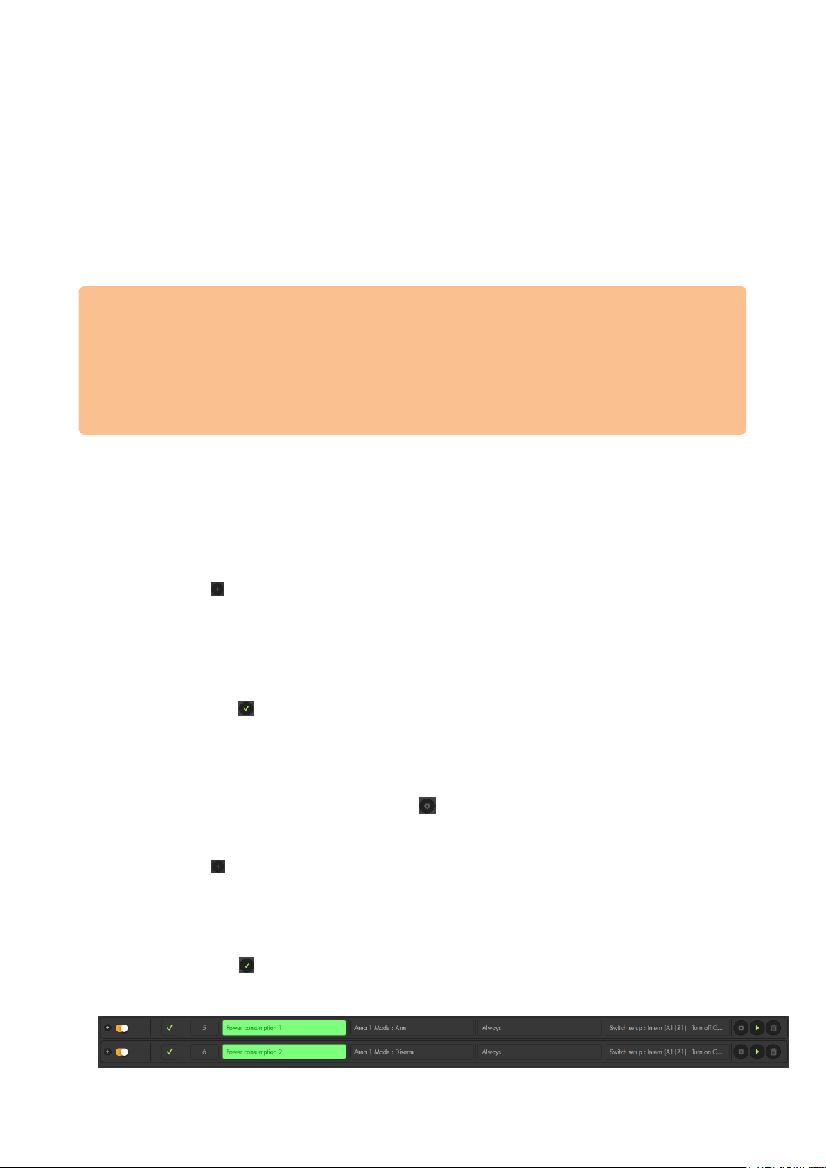
Examples
Please note:
Home automation rules are a very powerful tool to control the devices in your home.
However, due to the multitude of possible uses, we cannot offer an example for every
possible automation. This chapter aims to give you a brief overview how automations
work and how they have to be setup. Since each home and the devices connected to
each alarm panel are different, you need to define your own individual automations for
your needs.
Example 1 – reducing your power consumption
Aim: In order to reduce the power consumption of your devices in standby mode, you
can use a wireless plug or relay (area 1 zone 1) to switch off e.g. a television.
Settings:
Open the menu “Smarthome” “Automation” “Rules”
Click on in the rules menu.
Select a number for the new rule from the dropdown menu (the lowest free
number is selected by default).
Select “Condition” “Mode” “Area 1” “arm”.
Select “Schedule” “Always”.
Select “Action” “Switch setup” “Area 1 Zone 1” “Turn off”.
Click on the to the right of the rule.
Add the new rule to the currently active profile.
From now on, the alarm panel will switch off the selected wireless plug whenever the
alarm panel is armed. Thus, the power consumption is reduced. If you want to edit the
rule, you can do this anytime by clicking on .
In order to restore the power supply to your television when you come home, you have
to create the following second rule:
Click on in the rules menu.
Select “Condition” “Mode” “Area 1” “disarm”.
Select “Schedule” “Always”.
Select “Action” “Switch setup” “Area 1 Zone 1” “Turn on”
“Continuous”.
Click on the to the right of the rule.
Add the new rule to the currently active profile.
68
Page 69
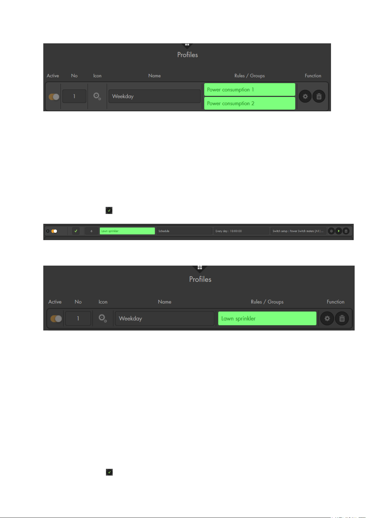
Example 2 – time control
Aim: How to switch on a lawn sprinkler that is connected to a wireless plug in area 1
zone 2 for two hours every evening.
Settings:
Create a new rule
Select “Condition” “Schedule”.
Select “Schedule” “Every day” and, then, select identical start time (e.g.
18:00).
Select “Action” “Switch setup” “Area 1 Zone 2” “Turn on” “2 hours”
Click on the to the right of the rule.
Add the newly set-up rule to an activate profile for activation.
Example 3 – automated shutter control
Aim: A shutter relay (zone 11) shall open the shutter only when someone is at home
(disarmed alarm panel) every morning 10 minutes before sunrise. In the evening, the
shutter relay shall close the shutter (irrespective of the mode of the alarm panel) 10
minutes after sunset.
Settings:
Create a new rule
Select “Condition” “Mode” “Area 1” “Disarm” and add the condition
“Mode” “Area 2” “Disarm”. Use “and” to connect these conditions.
Select “Schedule” “Sunrise” “-10 minutes”.
Select “Action” “Shutter setup” “Area 1 Zone 11” “Open”.
Click on the to the right of the rule.
69
Page 70
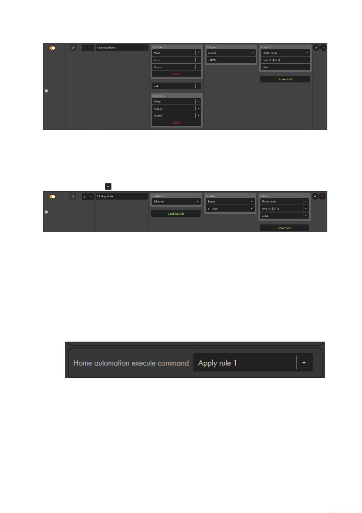
Create a second rule.
Select “Condition” “Schedule”.
Select “Schedule” “Sunset” “+10 minutes”.
Select “Action” Shutter setup” “Area 1 Zone 11” “Close”.
Click on the to the right of the rule.
Example 4 – Using a sensor triggered event, the “or” connection and night
schedule
Aim: We want to switch on a dimmable lamp for one minute if we pass by one of our
two motion detectors during the night.
Settings:
First, we need to open the edit sensor menu of our motion detectors (“Sensors”
“List” “Sensorlist”).
In both motion detectors, we set “execute home automation command” to “apply
rule 1”.
Now, we go to the menu “Smarthome” “Automation” “Rules”
Create a new rule
Select “Condition” “Triggered sensor action” “Area 1” “Sensor event 1”
Add another “condition” “Triggered sensor action” “Area 1” ““Sensor
event 1” and connect the conditions with “or”.
Select “Schedule” “Daytime” “Night”. Make sure that you have set your
location and date in “Alarm system” “Settings” “Date & Time”)
Select “Action” “Dimmer setup” “Area 1 zone 13” “Turn on” “60
seconds”.
70
Page 71
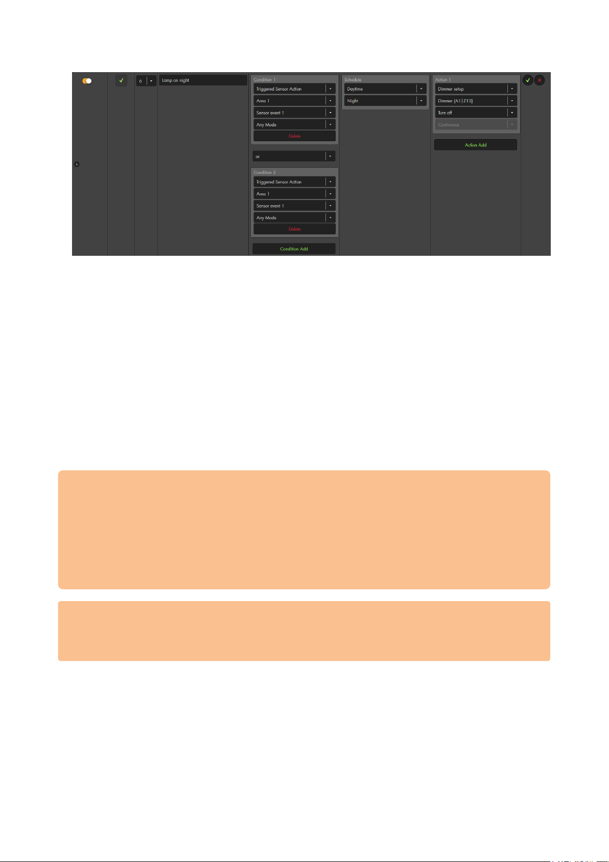
Please note:
You can use a sensor event (1-16) in multiple sensors.
Several home automation rules can be triggered at the same time by one sensor
event, e.g. to arm the alarm panel and at the same time switch on a wireless
power supply device or relay upon activation of the sensor.
„and“ connections allows you to define when an action should take place. Hence,
you can use a single sensor event for a multitude of different actions.
Example 5 – Action URL
The “Action URL” allows you to send out URL commands via your network. By using the
“Action URL” and CGI commands, you can control all kinds of devices (not limited to
devices by Lupus Electronics).
Please note:
In order to use the “Action URL” function, it is necessary to have a sound
knowledge of coding.
The possible CGI commands for your network devices can be found in the
devices manual or have to be requested from the devices manufacturer.
Before inserting the command in the alarm panel, make sure to test it beforehand
in your web browser (e.g. Firefox).
Make sure that all network devices are using the latest firmware.
In the examples below (5.1 – 5.3) we use the action URL method to control the
cameras. However, these specific commands are already pre-defined in the
alarm panel via the action “IP-Camera”. We show them here what can be done
with this function.
5.1 – Activate/deactivate the e-mail function of a camera (
Aim: The following example shows how to use the “Action URL” in order to activate the
e-mail function of a LUPUSNET HD IP camera (LE 9xx series) when you arm the alarm
panel. The IP address of the camera is 192.168.1.200. Username and password are
“Test”. The corresponding CGI command is “SetMail.cgi?Mail_Enable=1“.
The complete syntax is:
http://username:password@IP-address:Port/SetMail.cgi?Mail_Enable=1
Thus, with our test values:
http://Test:Test@192.168.1.200:80/SetMail.cgi?Mail_Enable=1
71
Page 72
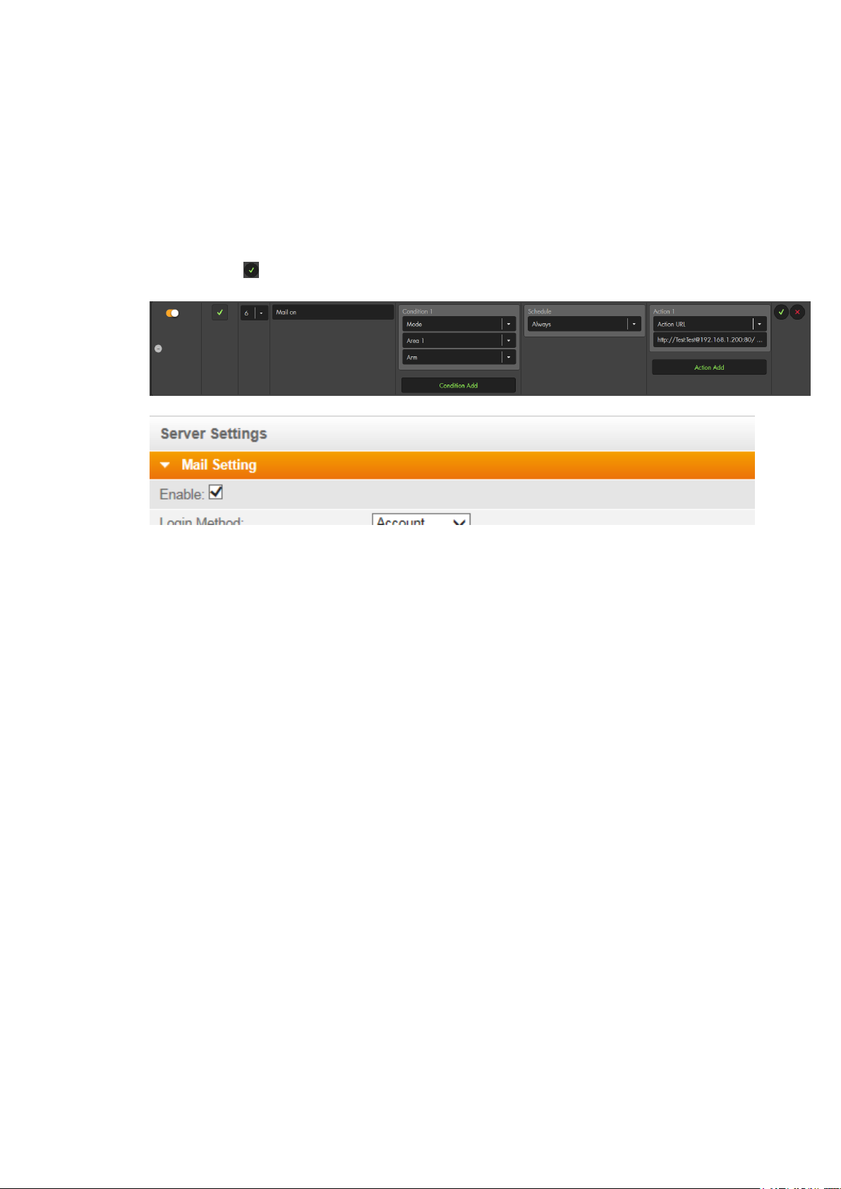
Settings:
Create a new rule
Select “Condition” “Mode” “Area 1” “arm.”
Select “Schedule” “Always
Select “Action” “Action Url” enter the following command into the blank
below (without quotation marks):
„http://Test:[email protected]:80/SetMail.cgi?Mail_Enable=1“
Click on the to the right of the rule.
Add the newly set-up rule to an activate profile for activation.
After you arm the alarm panel, the e-mail function of the camera is activated:
If you want to deactivate the e-mail function upon disarming of the alarm panel,
you need to create another home automation rule and use “condition” “disarm”
instead of “arm” and you need to change “Enable=1” (activates the e-mail
function) at the end of the CGI command to “Enable=0” (deactivates the e-mail
function).
5.2 – Activate/deactivate motion detection of a camera
Aim: The following example shows how to activate the motion detection of a LUPUSNET
HD IP camera (LE 9xx series) when arming the alarm panel.
The login information and IP address are identical to example 5.1. The CGI command to
activate the motion detection is “SetMotionDetect.cgi?md1_ena=1”.
“md1” refers to the motion detection area 1.
“ena=1” actives the motion detection.
“ena=0” would deactivate the motion detection.
In order to control more than one motion detection area at once, you need to combine
the commands using the “&” sign.
The complete syntax is:
http://username:password@IP-
address:Port/SetMotionDetect.cgi?md1_ena=1&md2_ena=1&md3_ena=1
Thus, with our test values:
http://Test:Test@192.168.1.200:80/SetMotionDetect.cgi?md1_ena=1&md2_ena=1&md3
_ena=1
72
Page 73
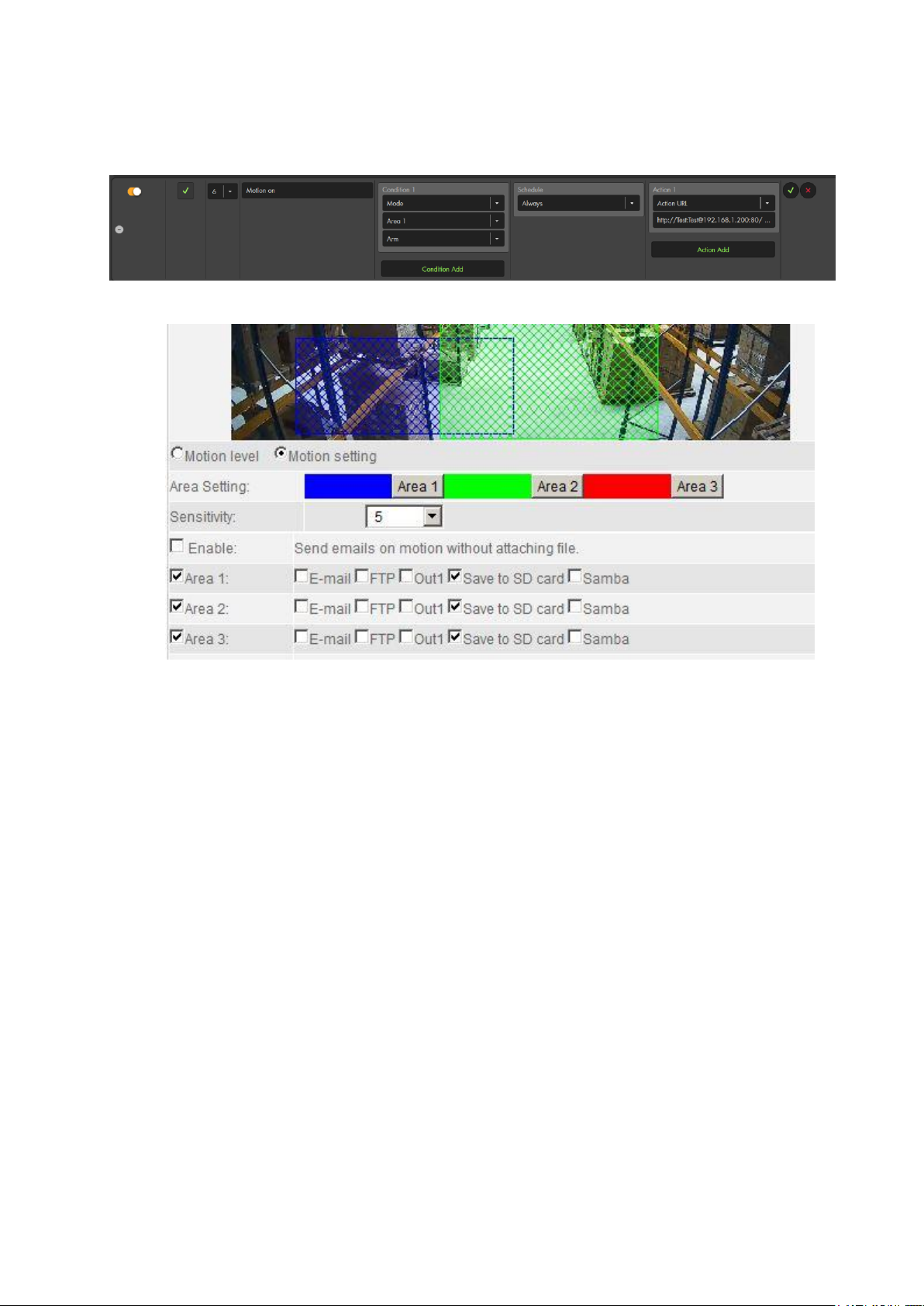
Settings:
The settings are identical to the settings in example 5.1. Only the “Action URL”
command is different
After arming the alarm panel, the motion detection areas of the camera are
activated:
If you want to deactivate the motion detection upon disarming the alarm panel,
you need to create another home automation rule and use “condition” “disarm”
instead of “arm” and you need to change “md1_ena=1” (activates the motion
detection of area 1) at the end of the CGI command to “md1_ena=0” (deactivates
the motion detection of area 1).
5.3 - Activate/deactivate motion detection of a camera
Aim: The following example shows how to activate the motion detection of a
LUPUSNET HD LE 20x (LE 201 / LE 202 / LE 203 / LE 204) when arming the alarm
panel.
The login information and IP address are identical to example 5.1. The CGI command to
activate the motion detection is:
cgi-bin/configManager.cgi?action=setConfig&MotionDetect[0].Enable=true
The complete syntax is:
http://IP-address:Port/cgibin/configManager.cgi?action=setConfig&MotionDetect[0].Enable=true&user=username
&password=password
Thus, with our test values:
http://192.168.1.200:80/cgibin/configManager.cgi?action=setConfig&MotionDetect[0].Enable=true&user=Test&pass
word=Test
73
Page 74
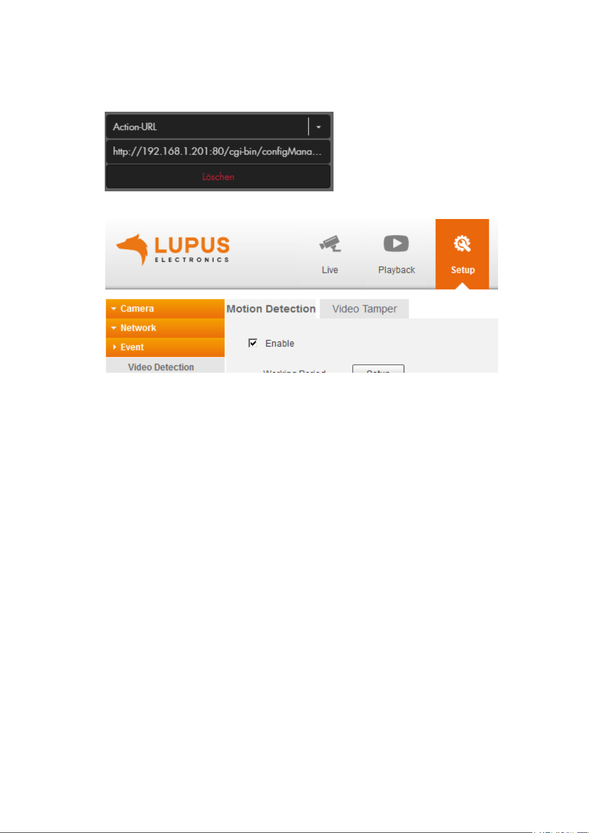
Settings
The settings are identical to the settings in example 5.1. Only the “Action URL”
command is different
After arming the alarm panel, the motion detection areas of the camera are
activated:
If you want to deactivate the motion detection upon disarming the alarm panel,
you need to create another home automation rule and use “condition” “disarm”
instead of “arm” and you need to change “&MotionDetect[0].Enable=true”
(activates the motion detection) at the end of the CGI command to
“&MotionDetect[0].Enable=false” (deactivates the motion detection).
Please note for LE 203
The camera LE 203 features an audio detection. You can use the following syntax
http://IP-Adresse:Port/cgi-bin/configManager.cgi?action=setConfig&AudioDetect[0].Muta
tionDetect=true&user=username&password=password to activate the audio detection.
Using MutationDetect=false disables the audio detection.
74
Page 75
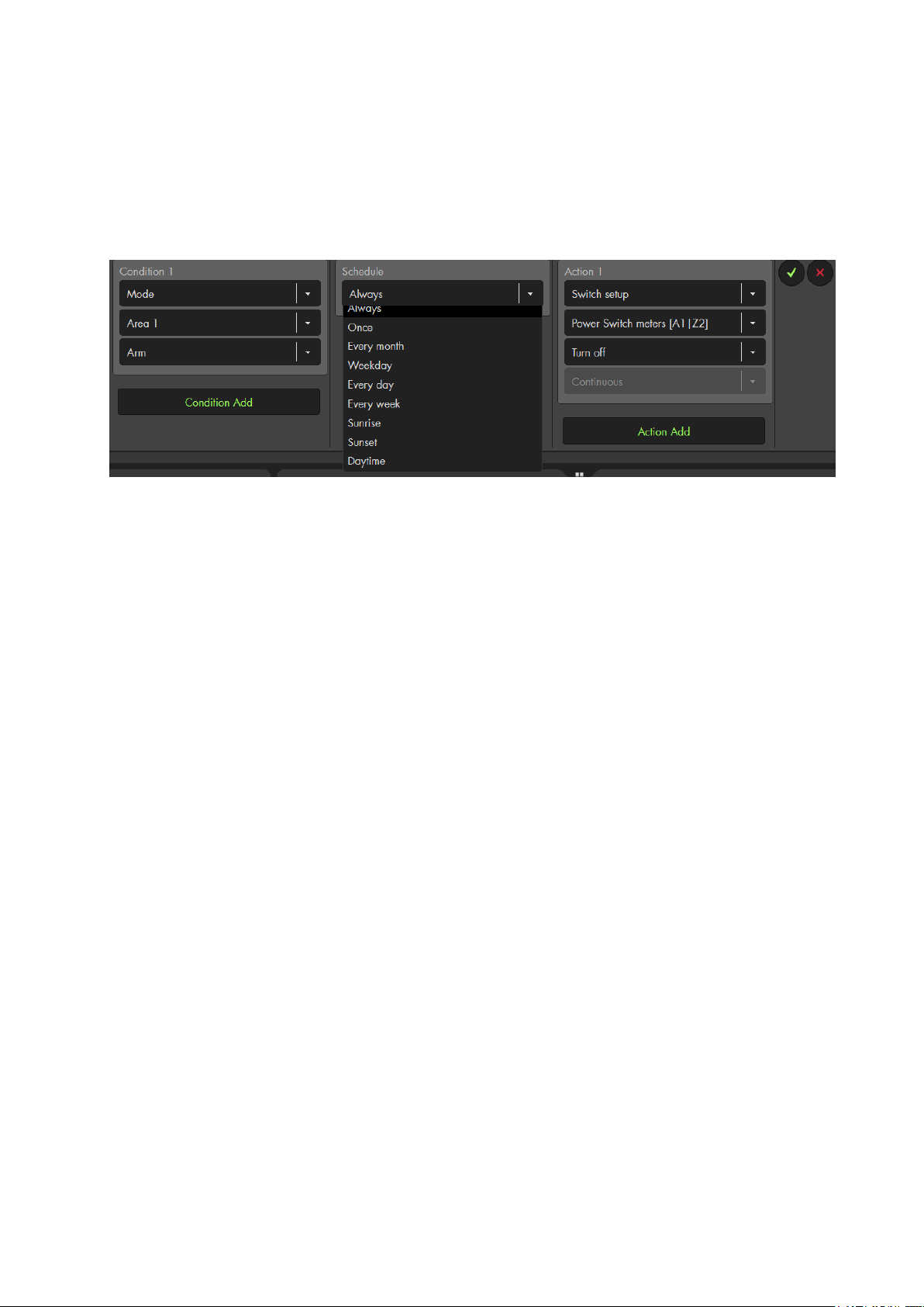
Examples of schedules:
The trigger for a home automation are the condition and the schedule. If the condition
and the schedule are met, the home automation is executed.
Depending upon if you have defined a point in time or a period in your schedule, the
home automation is executed under different circumstances.
Let us assume that whenever you arm your alarm panel (“condition” “mode” “arm”),
you want to switch off a wireless power plus at a certain time.
Point in time (once, every month, sunrise, sunset)
If the set point in time is reached and the condition is met (in this case the alarm panel in
arm mode), the power switch is turned off. In other words, the schedules triggers the
automation.
Period (always, weekday, every day, every week, daytime)
If the alarm panel is armed during the set period, the wireless is turned off. The condition
triggers the automation.
Hybrid: If e.g. “Every day: 12:00 – 24:00” was selected as the period, then, the action is
executed every day at 12 o‘clock if the alarm system is disarmed at the time. On the other
hand, the action is executed every day between 12:00 and 24:00 too, if the alarm panel
is set to disarm mode during this period.
Note:
If you arm the alarm panel by means of a schedule, the alarm panel will not
automatically by disarmed after the set time period. You need to set up a
second automation rule to disarm the alarm panel!
This is similar for any automation rule following a schedule, e.g. switching a
wireless power supply device on. You always need a second rule to switch it
off again.
75
Page 76
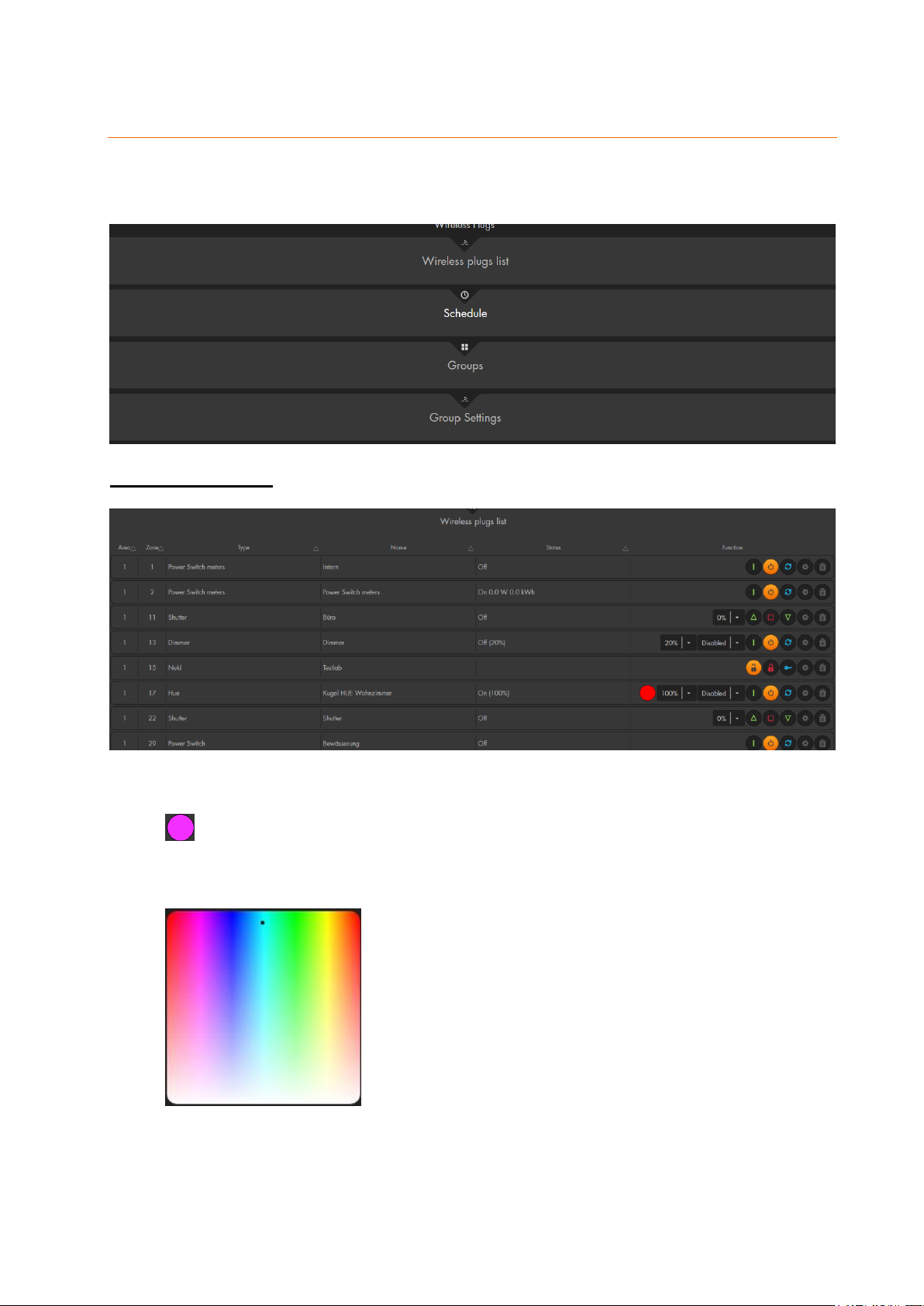
Wireless plugs
Shows a list of all integrated wireless power supply devices, relays, dimmers, and
Smarthome lights (PSS devices).
Wireless plugs list
The devices are listed with area, zone, type, name, and status.
Funktions
/ Colour circle (only Philips Hue colour Smarthome lights)
Clicking on the colour circle opens the colour selection that allows you to change
the colour of your Philips Hue Smarthome lights. To change the colour, the light
needs to be switched on.
76
Page 77
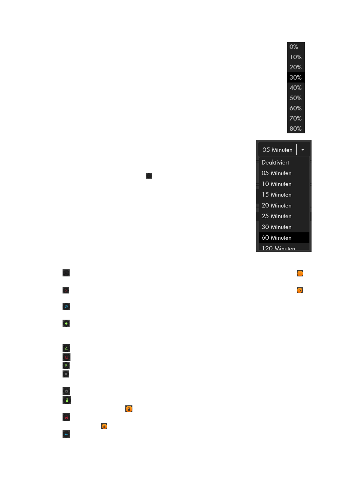
Percentage drop-down menu
o Allows you to adjust the brightness of your dimmer.
o Allows you to open / close your shutters to the selected degree
(100% = open / 0% = closed)
Time drop-down menu
o When the PSS device switched off, you can select
from the drop-down menu, for how long the selected
PSS device is to be switched on. Select the required
time and press the „ . If the PSS is switched on, this
dropdown menu has no function.
/ On: Switches the PSS device on. If the icon has an orange background , the
device is already switched on.
/ Off: Switches the PSS device off. If the icon has an orange background , the
device has already switched off.
/ Switch: Changes the status of the PSS device. If a PSS devices is switched
on, this button switches it off and vice versa.
/ Run trigger (only available if the trigger mode of the PSS device is activated):
Pressing this button switched the PSS devices on briefly and immediately switches
it off again.
/ Up (only shutter relay): Opens the connected shutter.
/ Stop (only shutter relay): Stops the connected shutter at its current position.
/ Down (only shutter relay): Closes the connected shutter.
/ Edit: Opens the sensor editing menu of the respective PSS device (see
chapter “Edit sensors”).
/ Delete: Deletes the sensor from the sensor list.
/ Unlock (only door lock): Unlocks your door lock. If the symbol has an
orange background , it is already unlocked.
/ Lock (only door lock): Locks your door lock. If the symbol has an orange
background , it is already locked.
/ Unlatch (only door lock): Opens the lock briefly (door buzzer)
77
Page 78
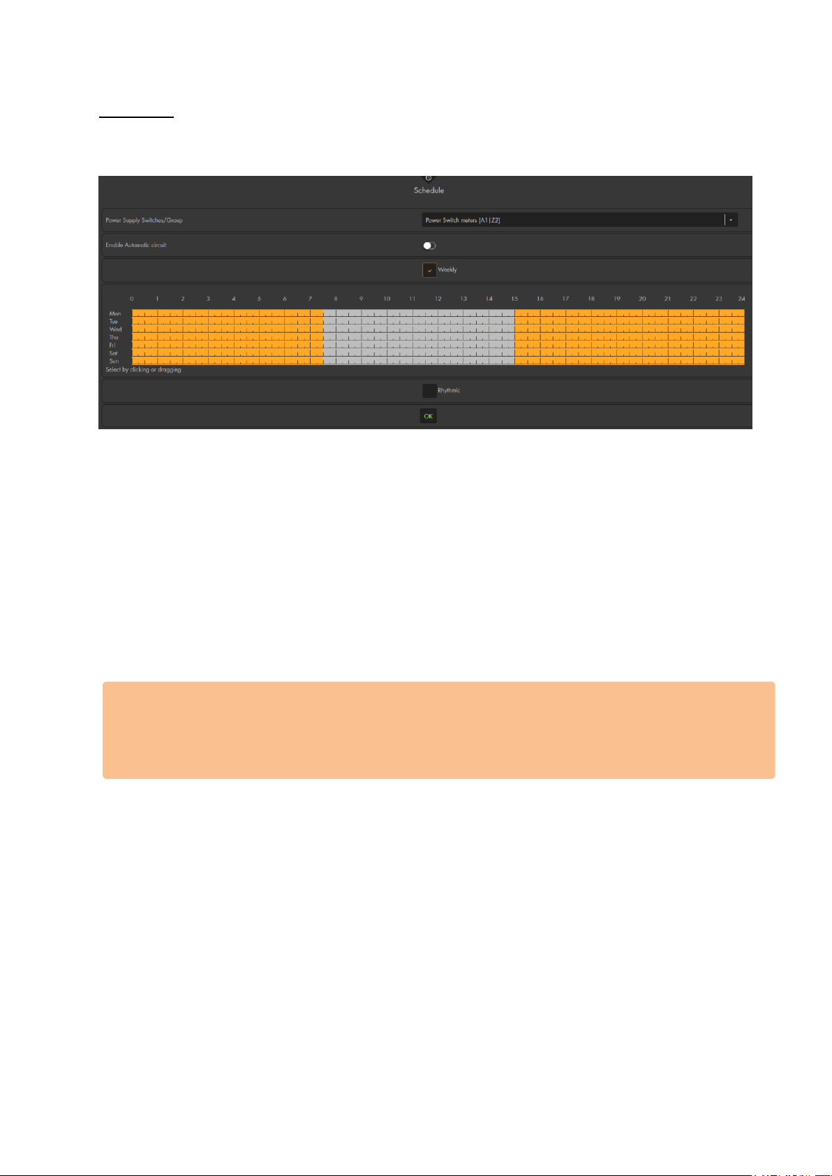
Schedule
The schedule menu allows you to define when a PSS device is switched on and when it
is switched off by means of a weekly schedule or a rhythmic interval.
Power supply switches / group
Select the device or group for which you want to define a schedule or rhythmic
interval.
Enable automatic circuit
You need to activate this function in order to apply the schedule or rhythmic interval for
the selected PSS device.
Weekly
Highlight the times the selected PSS device has to be active in the weekly schedule in
orange. Grey highlighting means that the selected PSS device is deactivated during
these times. If you still want to control your PSS device manually, please create a home
automation rule instead of using the schedule option.
Please note:
The difference between a home automation rule and the schedule is the following:
The schedule option checks and corrects the status of the PSS device every 15
minutes. If you would manually switch on the PSS device in the example image above
at 12:01, the schedule option would switch it off again at 12:15.
Rhythmic
Enter a fixed interval for how long the selected wireless power supply device / relay is
switched on and switched off. You could e.g. switch the selected wireless switch on for
ten minutes and then switch it off for 30 minutes. After the 30 minutes of deactivation,
it is switched on again for ten minutes and so on.
78
Page 79
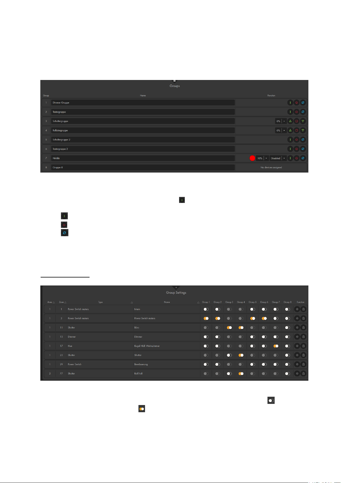
Groups
In the group settings, you can summarize wireless power supply devices and relays in a
maximum of eight groups and manually activate or deactivate them, activate them for a
specific period or activate/deactivate them in an automated manner.
Dropdown menu: When the PSS group switched off, you can select from the
drop-down menu, for how long the selected PSS device is to be switched on.
Select the required time and press the . If the PSS is switched on, this
dropdown menu has no function.
/ On: Switches the PSS group on.
/ Off: Switches the PSS group off.
/ Switch: Changes the status of the PSS group. If a PSS devices is switched
on, this button switches it off and vice versa.
Percent drop-down menu: Dims the group of relays with dimmer or Smarthome
lights.
Group settings
The group settings allow you to assign your PSS devices to 8 groups.
Group 1-8
In order to assign a device to a group, left click on the slider symbol . The
slider symbol changes to . If you click the symbol again, it changes to the initial
state and the device is no longer assigned to this group.
79
Page 80

Please note:
You cannot create groups consisting of different types of devices, since
they could have different functions.
A device can be assigned to various groups.
The following groups can be created:
o Switch groups: Remote controlled mains sockets, in wall relays.
o Light groups: Smarthome lights with colour selection e.g. Philips
Hue.
o Dimmer groups: In-wall relay with dimmer, light switch V2,
Smarthome lights without colour selection.
o Shutter groups: Shutter relay V1 / V2.
/ Edit: Opens the sensor editing menu of the respective PSS device (see
chapter “Edit sensors”).
/ Delete: Deletes the sensor from the sensor list.
80
Page 81
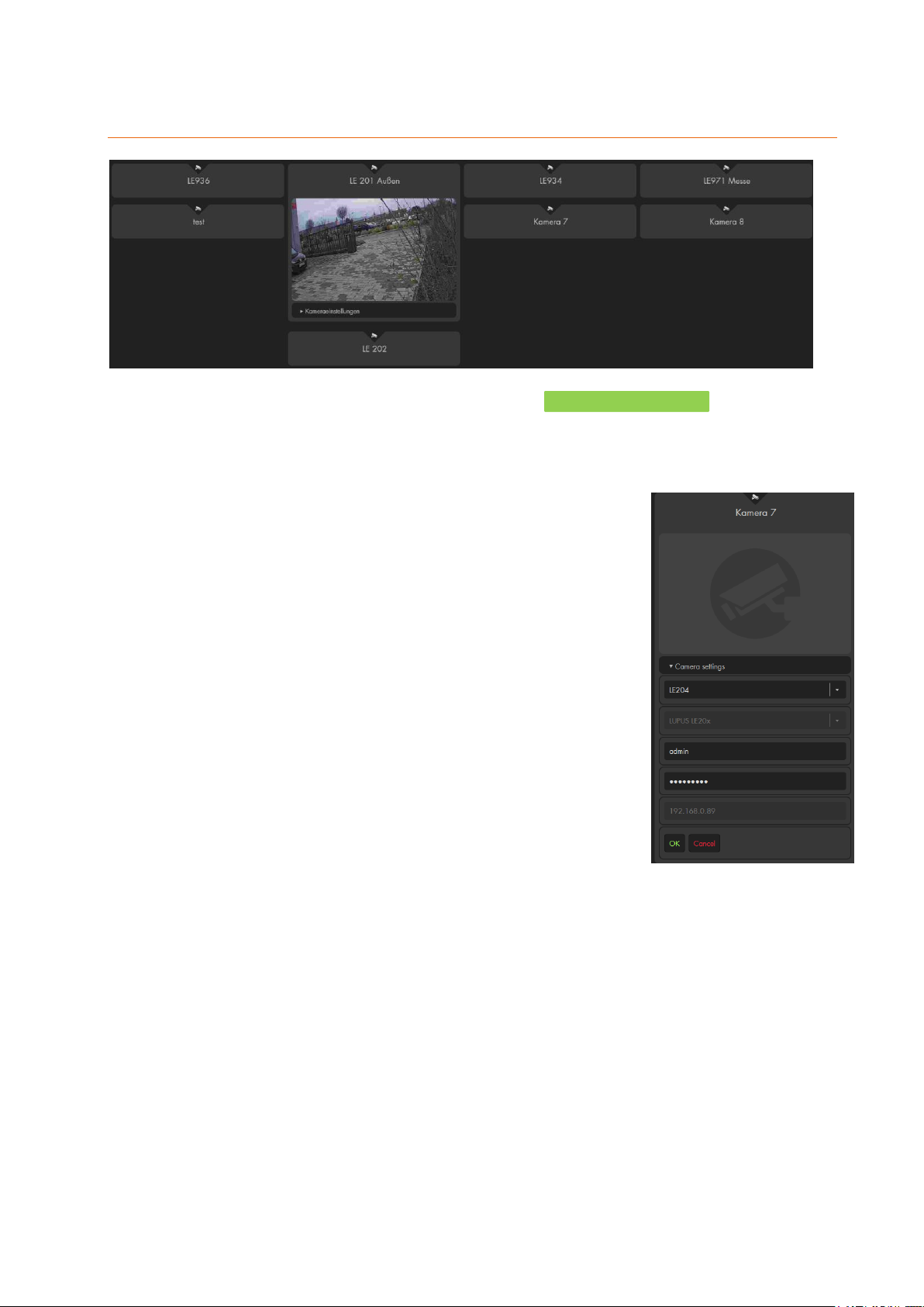
Cameras
In this menu you can connect up to eight live stream (XT1 Plus only four) of your LUPUS
IP cameras, as well as, most LUPUS recorder (8xx+, 8xxD1, 8xxHD, 8xxHD V2 series,
NVRs).
As of firmware 2.20 an IP finder is available in the alarm panel.
1. Open the settings of one of the available camera slots.
2. Select “Camera settings”.
3. Click on “Search” and wait until the XT finished the search.
4. Select your camera via the drop-down menu. The menu
lists the name of the camera. The corresponding IP
address of the camera is displayed below the camera
name after you have clicked on it.
5. Enter the username and password of the camera.
6. Save the settings with “OK” or cancel by clicking on
“Cancel”.
7. After you have saved the camera, you can enter an
optional name for the camera.
If you do not want to use the search function, or if your cameras
are not listed, you can always add them manually. Use the setting “LUPUS LE 20x” (LE
201 / 202 /203 /204) or “LUPUSNET HD” (LE 9xx series) to manually add cameras of
these types. Afterwards, you can enter an optional camera name and you need to enter
the username, password, and IP address of the camera.
If you want to connect a different LUPUS device (LE 200, LUPUS recorder) or a device
of another manufacturer, please select “Other” and enter the information to add the
image/video stream of that device. The requirement to add a device in this way is that the
device is able to supply a MJPEG stream. The URL to receive this stream needs to be
entered. Since this URL command is different for each manufacturer/camera, you need
to ask the manufacturer of your device for the correct stream.
We supply the command for our products in this manual and on our homepage.
81
Page 82

Examples:
Integration of a LE 200 camera
In order to display the live stream of your LE 200, you should update the firmware
of the camera to version 2.21.1.129_p1 (or later). The latest firmware can be
downloaded in the download section of the LE 200 on www.lupus-electronics.de.
Make sure to set the compression to MJPEG in the menu “Video” “Quality” of
your LE 200.
The URL consists of the following elements
IP-address: 192.168.123.10 Port: 88
Username: test Password: test
Image path: /cgi-bin/net_jpeg.cgi?ch=0
Example URL:
http://192.168.123.10:88/cgi-bin/CGIStream.cgi?cmd=GetMJStream&usr=
test&pwd=test
Integration of a LE HDTV V2 recorder (LE 8XX HD V2):
It is important that the latest recorder firmware is installed and the compression of
the extra stream is set to MJPEG via Main “menu” “Settings” “Camera”
“camera stream”.
The URL consists of the following elements
DVR address: 192.168.123.10 Port: 80
Username: test Password: test
Image path: /cgi-bin/mjpg/video.cgi? Channel: 1
Example URL:
http://192.168.123.10:80/cgi-
bin/mjpg/video.cgi?channel=0&subtype=1&user=test&password=test
Please note:
You need to subtract 1 from channel number. Channel 1 become channel=0 in the
URL command.
Integration of a LE HDTV recorder (first generation - LE 8XX HD, Nano
models excluded):
It is important that the latest recorder firmware is installed and the compression of
the extra stream is set to MJPEG via Main “menu” “Settings” “Camera”
“camera stream.”
The URL consists of the following elements:
DVR address: 192.168.123.10 Port: 80
Username: test Password: test
Image path: /cgi-bin/mjpg/video.cgi? Channel: 1
Example URL:
http://test:test@192.168.123.10:80/cgi-bin/mjpg/video.cgi?channel=0&subtype=1
Please note:
You need to subtract 1 from channel number. Channel 1 become channel=0 in the
URL command.
82
Page 83

Integration of an older 800 + / 800 D1 video recorder
The URL consists of the following elements:
DVR address: 192.168.0.155 Port: 10001
Username: test Password: test
Camera image: /cgi-bin/net_jpeg.cgi? Channel: 3
Example URL:
http://test:test@192.168.0.155:10001/cgi-bin/net_jpeg.cgi?ch=2
Please note:
You need to subtract 1 from channel number. Channel 3 become ch=2 in the
URL command.
These older recorder series can only display JPEG images and not a
livestream in the alarm panel.
Integration of a LE 20x camera (LE 201 / 202 / 203 / 204) via the “Other” option
The URL consists of the following elements:
IP-Address: 192.168.123.11 Port: 8080
Username: test Password: test
Image path: /cgi-bin/mjpg/video.cgi?channel=0&subtype=1
Example URL:
http://192.168.123.11:8080/cgi-bin/mjpg/video.cgi?channel=0&
subtype=1&user=test&password=test
Integration of a LUPUSNET HD camera (LE 9xx series)
The URL consists of the following elements:
IP address: 192.168.0.200 Port: 10030
User name: test Password: test
Image path: /GetData.cgi Stream: 2:
Example URL:
http://test:test@192.168.0.200:10030/GetData.cgi?CH=2
or
http://192.168.0.200:10030/GetData.cgi?CH=2&usr=test&pwd=test
Please note:
All examples only use sample data. You need to enter the username, password,
IP address, and, if required, channel of your camera (marked in red in the
examples).
[Only of you use “Other” to add the camera] In order to receive the live
stream of your cameras while you are not at home (not connected to your local
area network), you need to use your DDNS address instead of the IP address
and you need to create a port forwarding in your router.
Do not use the Internet Explorer! Internet Explorer does not support MJPEG
streams.
The PIR network camera cannot be added to this menu.
83
Page 84
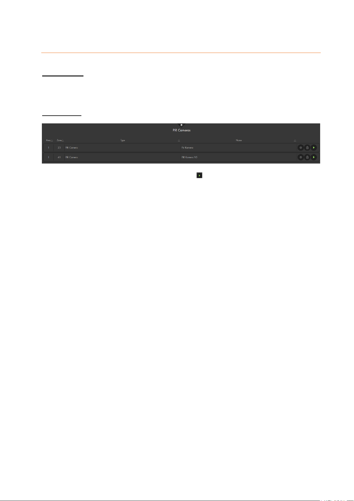
Capture
Image events
This menu displays all recent recordings of your PIR cameras, sorted by zone, picture,
and date. Click on a recorded picture to zoom in. A maximum of six PIR network cameras
can be added to the alarm panel.
PIR cameras
This menu displays the added PIR network cameras. allows you to manually trigger a
snapshot. The images are stored in “Smarthome” “Capture” “Image events”.
Please note:
You can only add up to six PIR network cameras to your alarm panel.
84
Page 85
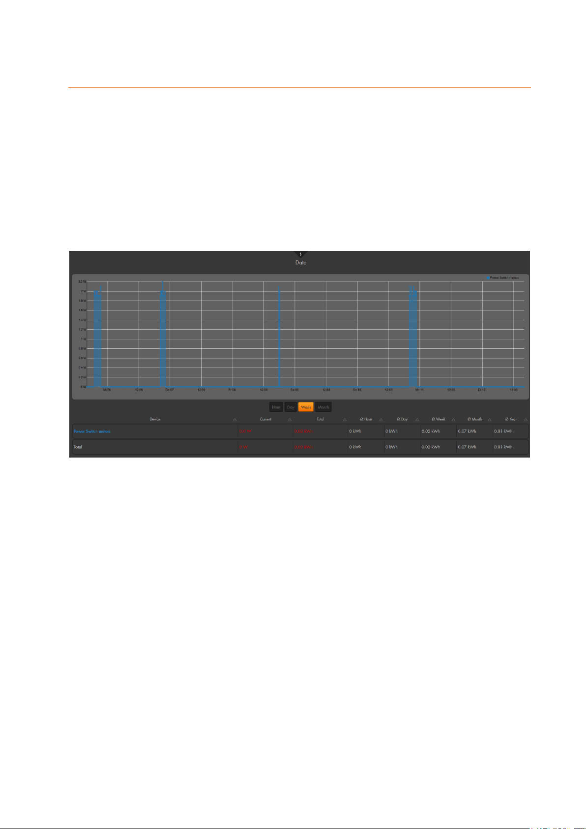
Power consumption
The table on the bottom of the screen shows the current, the average, and the
extrapolated power consumption of the added devices with electric meter (e.g. remote
controlled mains socket or in-wall relay # 12051).
You can select if you want to display the power consumption of the last hour, day, week,
or month. Depending on your selection, the graph is adjusted.
Each device with power meter is displayed in a different colour, which superimpose each
other in the graph. If you want to hide the graph of a device, click on the name above the
graph. Click again to display the graph of the device again.
The power consumption of the PSS devices is saved at intervals of ten minutes or, if the
consumption deviates within this interval by 2 watt and 5%. Additionally, you can view the
consumption values via the menu “System” “Logs” “Sensor messages”
Please note:
Depending on the amount of integrated PSS devices and the amount of saved
data, it may take a few minutes until the graph is compiled and the page is shown!
In order to reset the values in this menu, you need to delete the PSS device and
add it again to the alarm panel.
85
Page 86
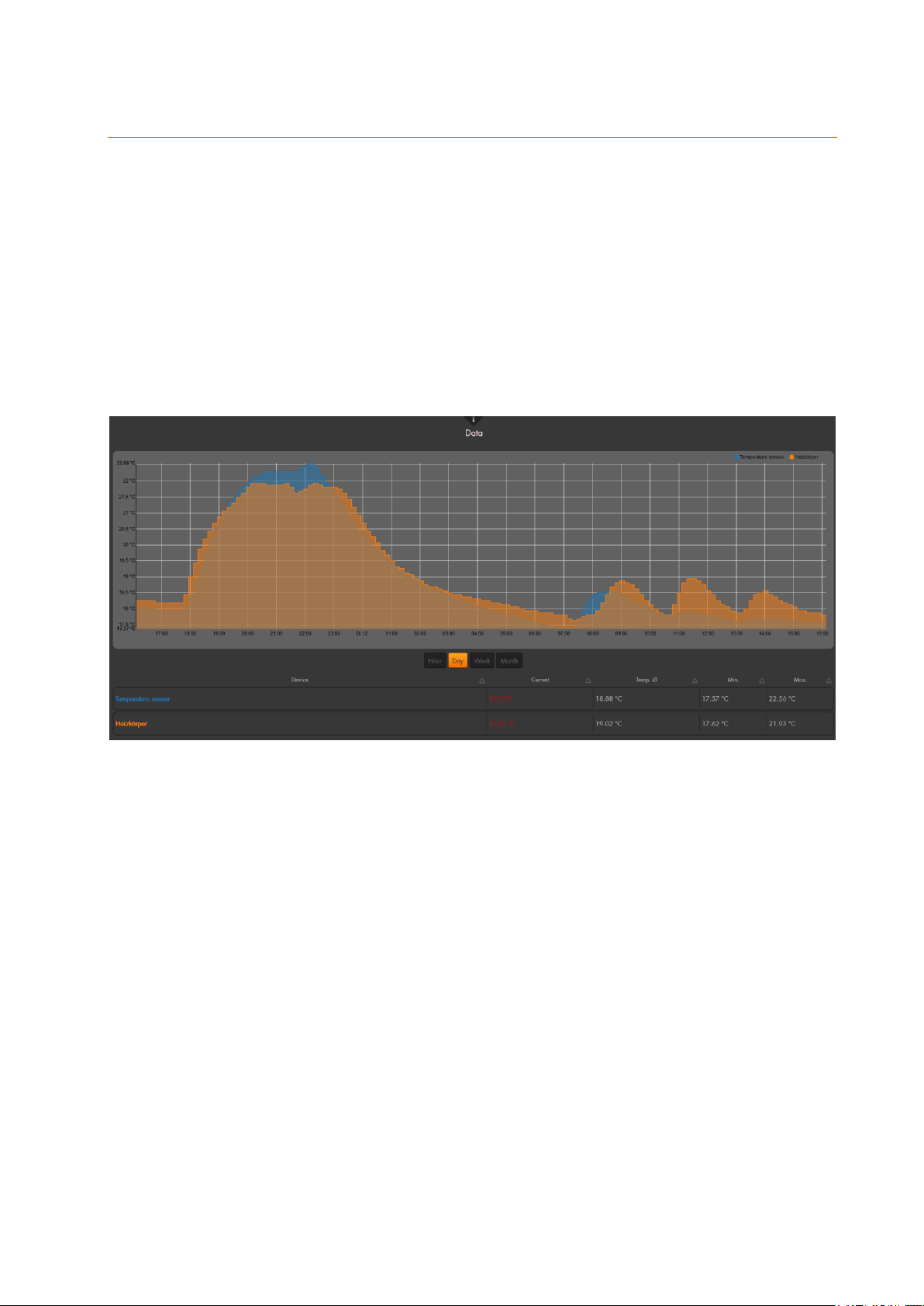
Temperature history
The table at the bottom of the screen shows the current temperature of your temperature
sensors, as well as, the average, minimum, and maximum temperature.
You can select if you want to display the temperature graph for the last hour, day, week,
or month. Depending on the selected period, the temperature profile graph displayed
above the table changes.
Each temperature sensor is displayed in a different colour, which superimpose each other
in the graph. If you want to hide a graph of a temperature sensor, click on the name above
the respective graph. Click again to display the graph of the sensor again.
The temperature data are saved at intervals of ten minutes. You can view the temperature
details via “System” “Logs” “Sensor messages”.
Please note:
Depending on the amount of integrated temperature sensors and the amount of
saved data, it may take a few minutes until the graph is compiled and the page is
shown!
In order to reset the values in this menu, you need to delete the temperature sensor
and add it again to the alarm panel.
86
Page 87
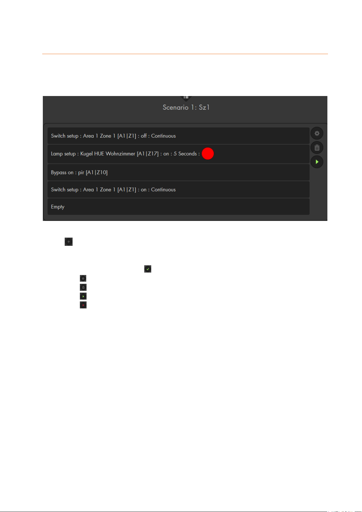
Scenarios
Up to 16 scenarios with up to five automation rules each can be set up. A scenario is a
combination of the individual commands. When you perform a scenario, all rules of this
scenario are performed at once.
allows you to create a new scenario.
You can assign a name for each scenario for reasons of clarity.
Use the drop-down menu to select up to five actions for your scenario.
Save your scenario with .
Use to edit your scenario.
Use to delete your scenario.
Use to manually trigger your scenario.
Use to discard your last (not saved) changes.
Please note:
A scenario can be triggered by nearly all sensors and, of course, the scenario
switch (see chapter “edit sensors”).
In the menu “Smarthome” “Automation” “Rules”, your can select a
scenario as an action.
In the home screen (GRID) of the alarm panel, you can place a scenario app
to trigger your scenario.
87
Page 88
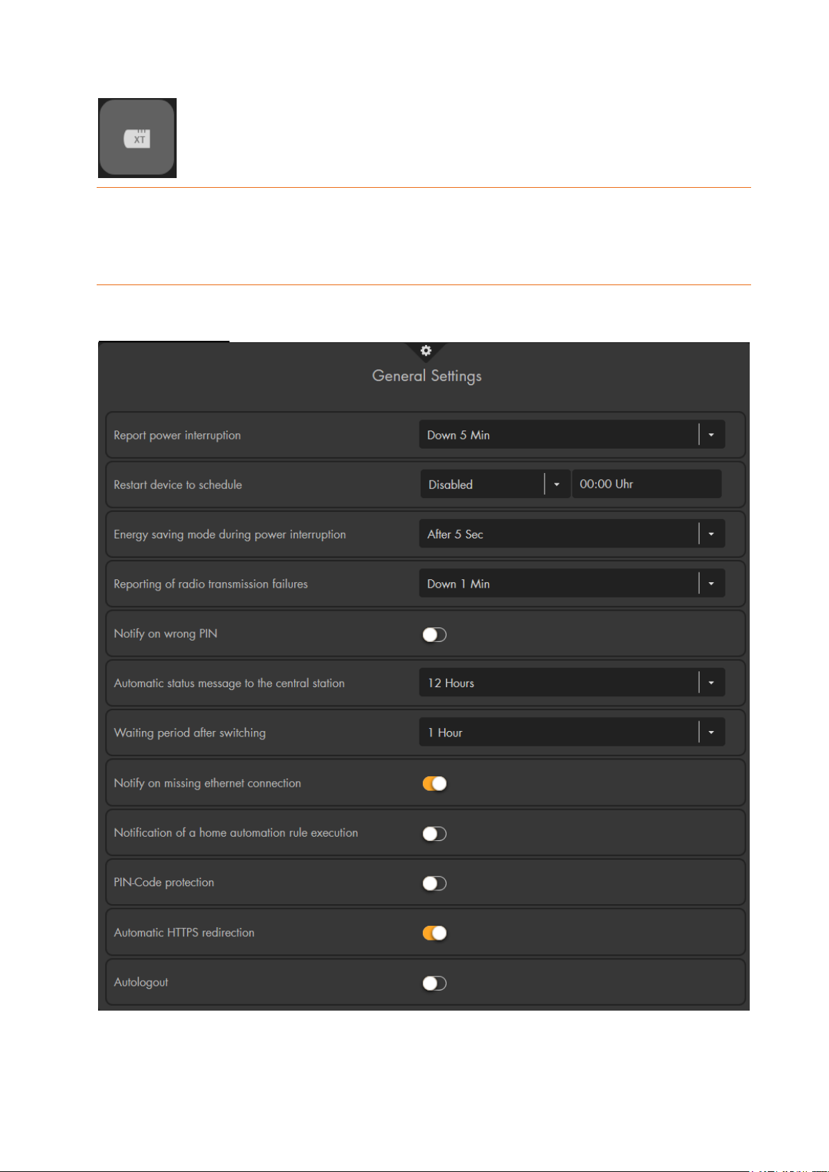
Alarm system
Comprises the sub-menus settings, siren settings, report, and PIN codes.
Settings
Use this menu to define the general settings, area, and alarm settings.
General settings
Report power interruption
Specify the time after which the alarm panel reports a power failure (Contact ID, e-
mail, SMS, etc.).
88
Page 89

Restart device to schedule
Use this function to schedule the regular restart of the alarm panel. After enabling
this option, it takes 24 hours until it is performed for the first time. Hence, it is not
possible to test a “restart in 5 minutes” with this option.
Please note: After a restart, the alarm panel has no information about the sensors
and all sensors (even open door contacts) are listed with “N/A”. If a sensor changes
its status from “N/A” to “open” (because it was open before the restart), an alarm
is triggered if this sensor should normally trigger an alarm in the current mode of
the alarm panel.
Energy saving mode during power interruption
Specify the time after which the alarm panel is to enter the energy saving mode in
case of power failure. It ends immediately in case of alarm.
Reporting of radio transmission failures
Enable this function if the alarm panel is to report radio interferences (e.g. by email, text message, contact ID, etc.) in case they are longer than the selected
duration (one or two minutes). No acoustic alarm is triggered.
Notify on wrong PIN
If this option is enabled, the alarm panel will notify you via Push message and email if a wrong PIN code was used. It is required that these messaging methods
are available.
Automatic status report to the central station
Specify the intervals at which the alarm panel is to report the status to the security
firm. Thus, the security firm recognises that the alarm panel is online. It is
necessary to set Contact ID to “all events” (recommended setting) or to “status
events” (alarms are not transmitted – not recommended). If you select “alarm
events”, status events, including this status report, are not transmitted to the alarm
service station.
Waiting period after switching
Specify how long the alarm panel has to wait until it sends the first status report to
the security firm after it was started.
Notify on missing Ethernet connection
Specify whether you want to hear a regular audio warning in case the network
connection is interrupted (or no Ethernet cable is connected). If this function is
disabled, the error LED does not signal a missing Ethernet connection.
Notification of a home automation rule execution
If this function is enabled, you receive a message by contact ID, e-mail, text
message, telephone, or push notification when an automation rule is executed.
Additionally, it is required that the condition “Automation rule” in the respective
notification drop-down menu (as condition / filter) is activated.
Protect PIN code
If this function is enabled, the keypad will be locked and will not react to any inputs
for 15 minutes after an incorrect PIN code was entered five times!
Automatic HTTPS redirection
By default, this option is enabled to ensure that only the SSL encrypted connection
(port 443) to the alarm panel is used. If you disable this option, against which we
strictly advise, you can also use the unencrypted port 80.
Autologout
By default, this option is enabled. After you have been inactive in the webinterface,
the alarm panel logs you out automatically.
89
Page 90
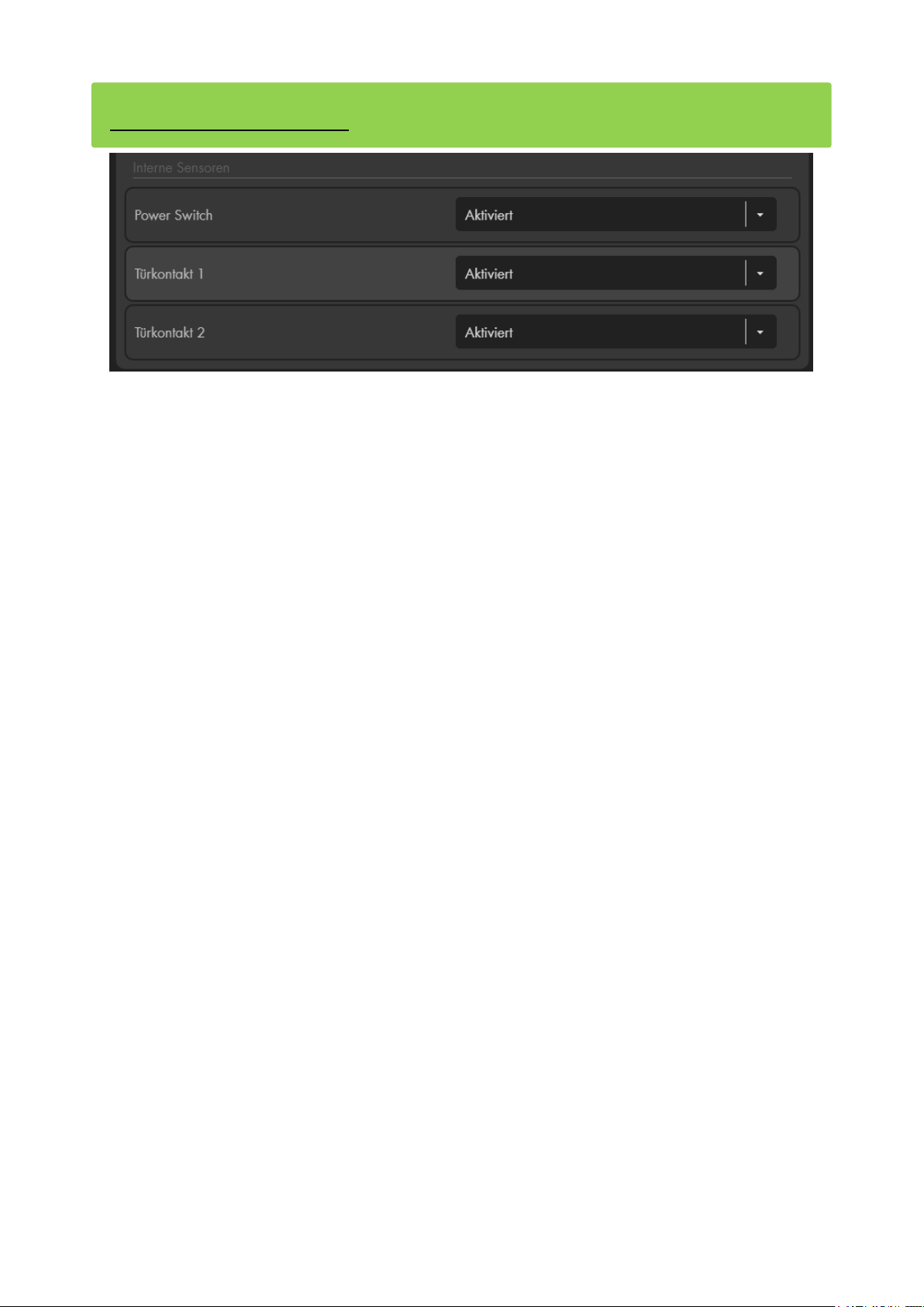
Internal sensors (only XT3)
In your sensor list, you find two “door contacts (intern)” and one “power switch (intern)”.
More information about these can be found in the chapter “The internal I/O terminal of the
XT3”.
In case you are not using these connectors, you can deactivate them via in this menu.
Afterwards, they are also removed from the sensor list.
90
Page 91
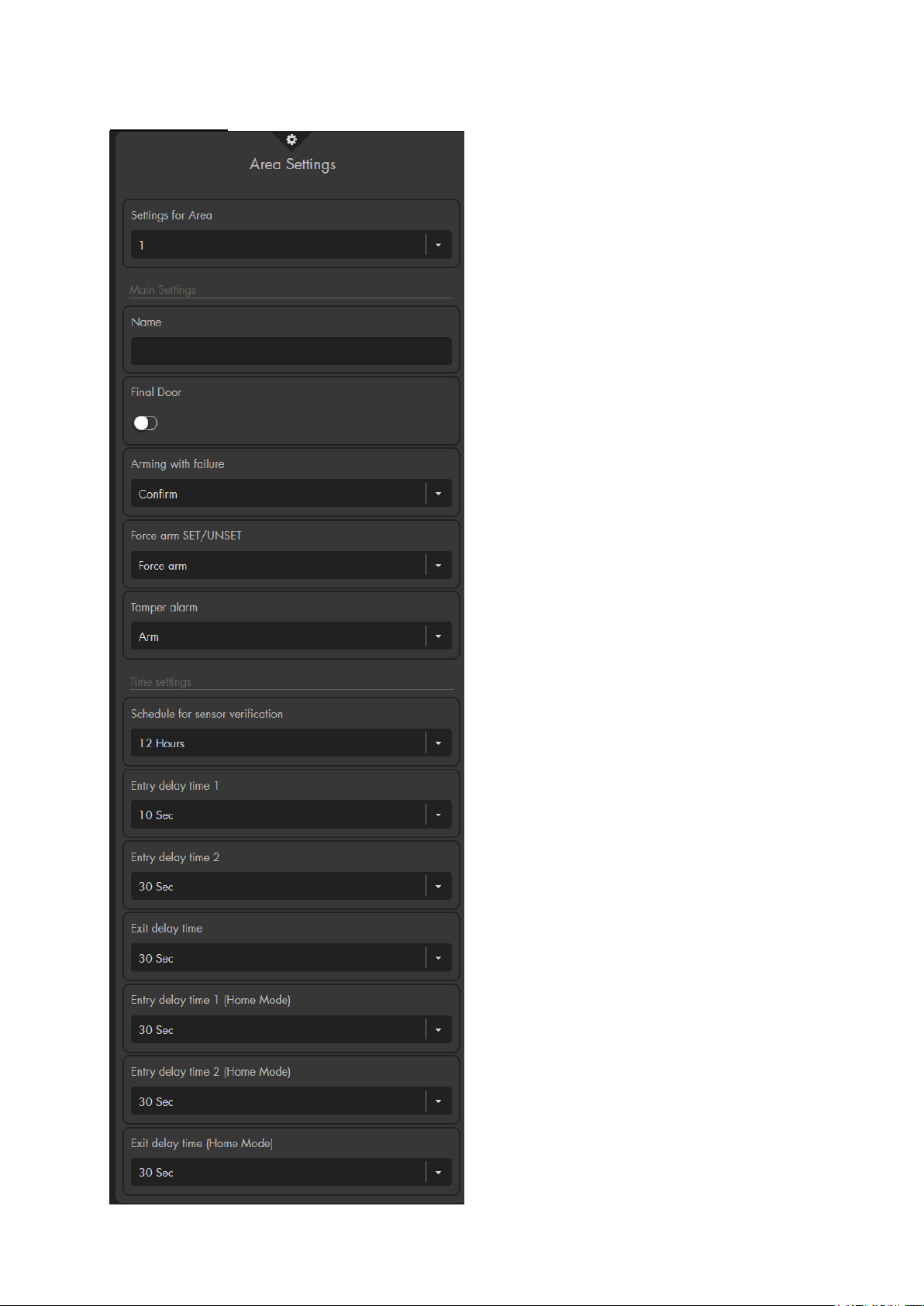
Area settings
Settings for area
Specify for which area the following
settings shall apply.
Main settings
Name
You can name the selected area. The
name will be included in e-mails/text
messages from the alarm panel.
Final Door
Activate this option if you want to arm the
alarm panel when the last open door
contact is closed during the exit delay.
Arming with failure
o Confirm (default setting): If you
attempt to arm the alarm panel while
an error is detected (system errors,
batteries and power supply, Contact
ID, SMS, IP-Ping, GSM, open
sensors, or other notifications by
sensors), a brief error message is
displayed in the web interface and the
panel emits two brief signal tones –
the alarm panel will not switch to arm
mode. If you attempt to arm the alarm
panel again within ten seconds, the
alarm panel will switch to arm mode
irrespective of any errors.
Note:
The errors are listed in the menu
“System” “Status” “Panel” or in
the “quick access” “Device errors”.
o Force arm: The alarm panel is
directly armed irrespective of any
errors (tampering, battery and power
supply, open door, etc.).
Force arm SET / UNSET
This setting is identical to “arming with
failure,” but is only for the arm function via
the SET / UNSET. If this option is set to
“confirm,” the sensor that should arm the
alarm panel, needs to send out the arm
command twice in a span of ten seconds
for the alarm panel to arm. If this does not
take place, the alarm panel stays in
disarm mode. If this function is set to
“force arm” (default), the alarm panel is
armed irrespective of any errors or open
sensors.
91
Page 92

Tamper alarm
o Arm (default): In case of a tampering alarm, the sirens sound an alarm only
in arm mode. They remain silent in all other modes (Disarm, Home 1-3).
o Always: In case of a tampering alarm, the sirens always sound an alarm –
irrespective of the alarm mode of the alarm panel.
Time settings
Schedule for sensor verification
At regular intervals, the alarm panel checks if the added sensors are still connected
to the alarm panel. We highly advise you keep this option enabled. If a sensor does
not send a status signal to the alarm panel during this interval, the alarm panel lists
this as an error, the sensor is marked as “out of order”, and the alarm panel emits
a notification sound every 30 seconds. Depending on your setup, you are notified
via contact ID, e-mail, SMS, or Push-Notification.
Please note:
o The alarm panel receives status information from every sensors on a
regular basis (every 30-50 minutes).
o After a reboot of the alarm panel, there are no status information available.
Hence, the sensors are displayed without their current status. If a sensor is
open and its status changes from “N/A” to “open”, an alarm is triggered, if
the sensor should trigger an alarm in the current mode of the alarm panel.
Entering delay (1 and 2)
If you enter your house while the alarm panel is armed, you may need a certain
time to disarm the alarm panel by e.g. entering the code in the keypad. This setting
allows you to specify the required delay time until an alarm should be triggered.
This only applies to sensors with the ‘arm response’ “Entry delay 1 or 2” (see
chapter “Edit sensors”). Sensors with the attribute “Burglar alarm instant” will
always trigger an alarm immediately.
Exit delay
If you arm the alarm panel, you may need a certain time to leave the house. This
option allows you to set this delay time. After the delay has expired, the alarm panel
is armed.
Please note:
o Additionally, you need to enable the option “mind the exit delay” in the
sensor edit menu of each sensor that should not trigger an alarm during this
delay time. This option can be set individually for every alarm mode.
o The exit delay is active irrespective of the way you arm your alarm panel
(e.g. Keypad, Remote control, Tag Reader V2, Web browser, or App).
Entry delay time 1 & 2 (home modes)
If one of the home modes is active and a sensor with the setting delay upon entry
(1 or 2) for home 1 / 2 / 3 response is triggered, the delay time is started and an
alarm will only sound if the alarm panel is not disarmed in the set time.
Exit delay time (home modes)
If the Home mode is activated e.g. via the keypad, you will usually need time to
leave the house or premises. You can set the delay before the alarm is triggered
here. Please observe the note under “Delay upon exit”.
92
Page 93
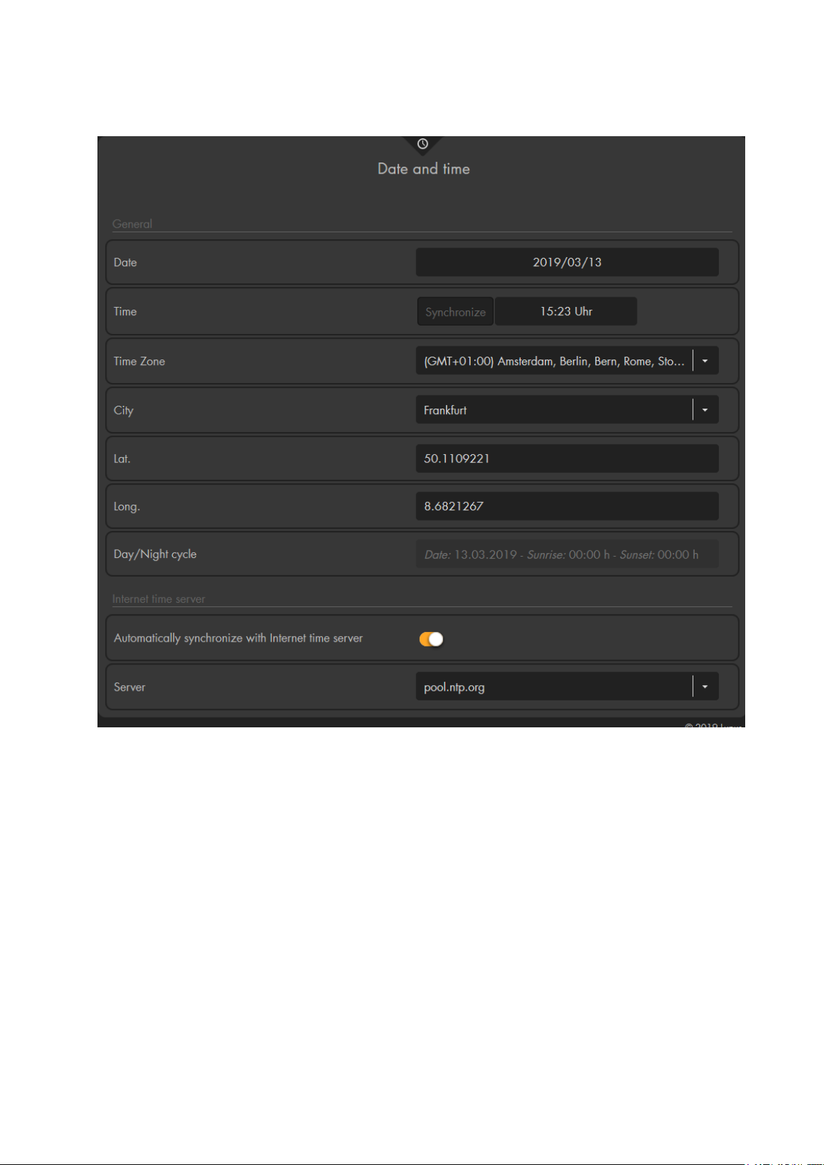
Date and time
General
Date
Enter the current date (YYYY/MM/DD).
Time
Allows you to manually enter the current time (HH:MM). Click on “Synchronize”
to use the current time of your computer.
Time zone
Enter your current time zone.
City
Allows you to choose city close to your location from a drop-down list to get the
times of sunrise and sunset of this city. Thus, you can use the automation
schedules for sunrise and sunset in the automation menu!
Latitude / longitude
As an alternative to selecting the city, you can enter the exact coordinates of your
location to get the exact times of sunrise and sunset.
Day/night cycle
Shows the time of sunrise/sundown for the current day (depends upon the choosen
93
Page 94
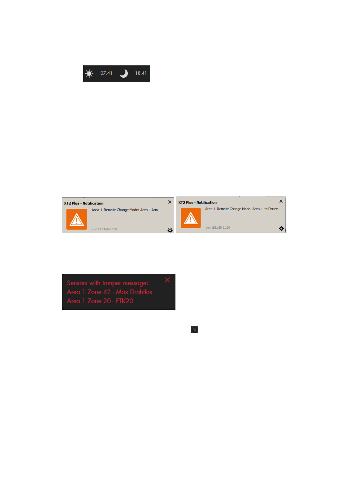
location).
Please note:
o You can display the sunrise and sunset times in the quick access menu.
Internet timeserver
Automatically synchronize with internet time server
If you enable this option, the time of the alarm panel synchronizes regularly with
the specified internet timeserver (if available).
Server
Select a timeserver from the list to synchronize the current time with.
Display
Browser-Notifications
If this option is enabled, you receive a small pop-up window in your browser
anytime something is happening, e.g. mode change, door bell, alarm, etc.
Show warning pop-up
If this option is enabled, you receive a pop-up after logging in or reloading the page
that displays errors (e.g. low battery, tampering contact open, etc.). You can close
the pop-up by clicking on the X at the top right corner of the pop-up.
Please note:
o The option “buy batteries now” brings you directly to the LUPUS
Electronics website.
o Before buying batteries, check that it are the correct ones. Over the years
we changed some of the used battery types.
Background image
You can define a background image for the web browser of the alarm panel. To do
so, you need to enter the URL of the image path.
Set theme
You can select between the dark and light theme of the web interface.
Language
Allows you to change the language of the web interface of the alarm panel.
Currently, German, English, Francais, Espanol, Italiano, and Lietuviškai are
supported.
94
Page 95
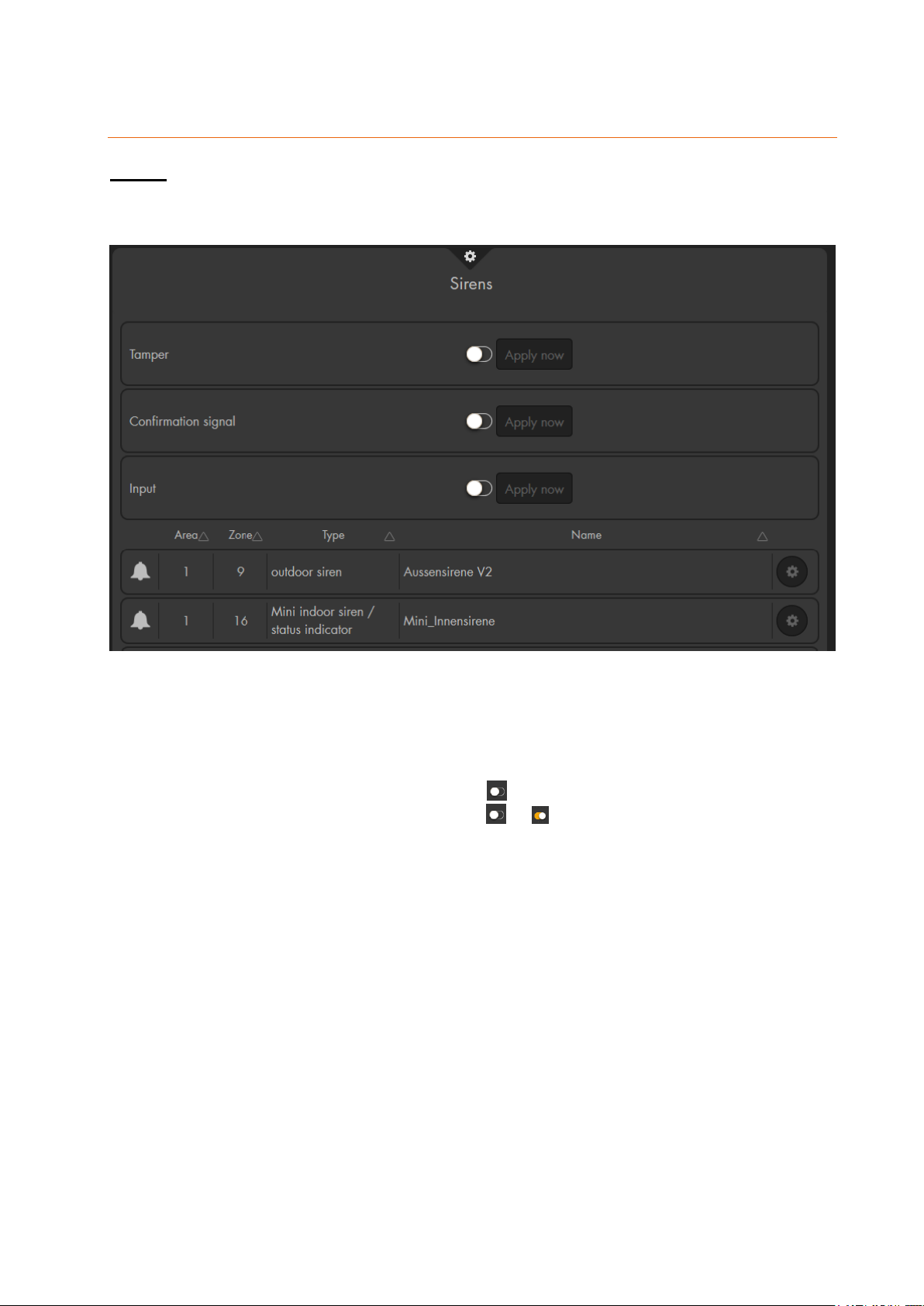
Siren settings
Sirens
This menu consists of two parts. The upper part allows you to transmit settings to all
connected indoor and outdoor sirens. The lower part lists your connected sirens and
allows you to enter the sensor edit menu of the sirens.
This menu allows you to configure “external” sirens that are added to the alarm
panel. It is not possible to configure the internal siren of the alarm panel in this
menu.
All settings in this menu are only transmitted and saved on the siren(s). The web
interface does not display the current setting of the sirens. After the transmission,
the alarm panel displays the setting as again.
To transmit the selected setting, select or and press “Apply now”.
The sirens will sound a notification sound to acknowledge that the new settings
have been received.
The new configuration is send to all connected sirens. If you want to set multiple
sirens differently, you need to add them later to the alarm panel or temporarily
disconnect the ones you do not want to change from their power supply.
It is not possible to display the current setting of a siren.
Tamper on/off
Deactivates the tampering contact of all currently connected “external” sirens for one
hour (useful e.g. to change the batteries).
Please note:
If the tampering contact is disabled, the siren does not transmit status updates to
the alarm panel anymore. For that time, you cannot see the current status of the
tampering contact via the menu “Sensors” “List” “Sensor list”.
Attention! If you open the siren without disabling the tampering contact, the
acoustic alarm of the siren will sound – even if the siren is not connected to the
95
Page 96
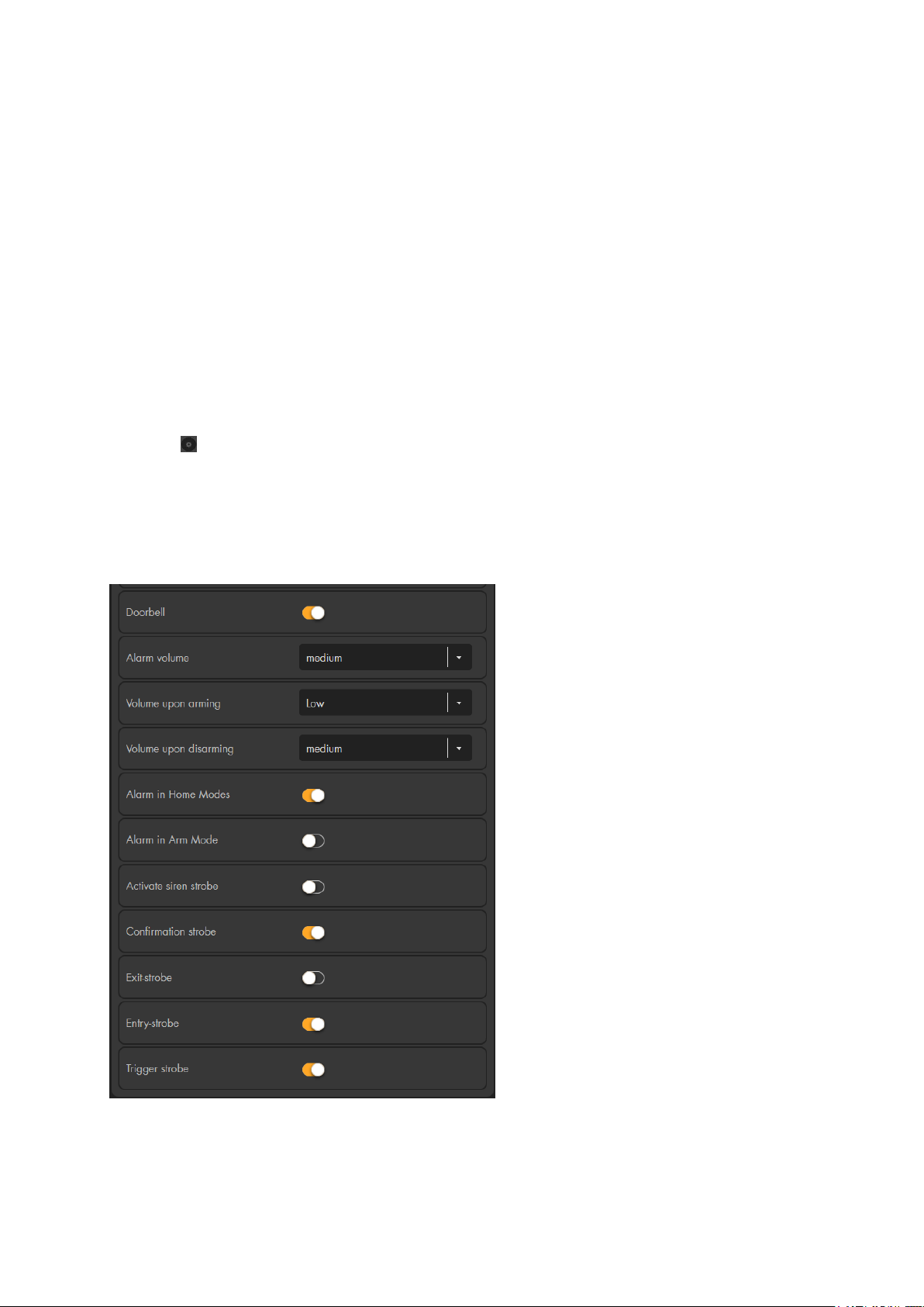
alarm panel! In this case, you should wear ear protection and disconnect the siren
as quick as possible from its power supply.
Confirmation signal on/off (with Arm / Disarm)
With this function active, the siren will sound one signal tone when arming and two
signal tones when disarming the alarm panel.
Please note:
If the tampering contact of the siren is open when arming or disarming the alarm
panel, five short acoustic signals sound even though the confirmation tone is
disabled. This can happen before the alarm panel displays an open tampering
contact, giving you the possibility to react before a tampering alarm is triggered.
Input on/off
With this function active, the external siren(s) sound confirmation signals for the
duration of the defined delay until the system is armed.
Advanced settings
Click on to change the settings of your siren. After you have selected the settings to
your preference, they are saved and the siren sounds a brief sound.
This menu is only available for the outdoor siren and small indoor siren V2 (sold since
Autumn 2018). Depending on the type of siren, this menu may look different (e.g. the
small indoor siren does not have the options to set LEDs, since this siren is not
equipped with LEDs.
Doorbell
Specify, whether the siren is to give
an acoustic signal with the “Doorbell
function”.
Please note:
In the menu “Siren settings”
“Sound settings” “Area settings”
“Doorbell” ”All sirens off” you can
also disable the doorbell sound for all
sirens.
Alarm volume
Define the siren’s volume in case of
alarms (loud, medium, quiet, mute).
Volume upon arming
Define the volume of the confirmation
sound when arming.
Volume upon disarming
Define the volume of the confirmation
sound when disarming.
Alarm in home mode
Specify, whether the siren is to trigger
an alarm in case of a burglary while
the alarm panel is in home mode.
Alarm in arm mode
Specify, whether the siren is to trigger an alarm in case of a burglary while the alarm
panel is in arm mode.
96
Page 97
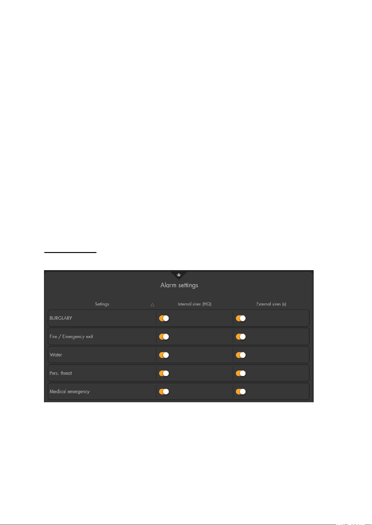
Activate siren strobe
Name
Type of alarm
Burglary
Burglary alarm (instant, delayed, follow)
Fire/emergency exit
Fire, heat, and smoke alarm
Water
Water alarm
Specify whether the LEDs of the siren are to flash after the acoustic alarm has ended
until the system is disarmed again.
Confirmation strobe
Specify, whether the siren is to flash for confirmation, when the alarm mode of the
alarm panel changes (Arm/ Home / Disarm).
Please note:
If you disable the “confirmation signal” in the siren settings above, the confirmation
strobe is also disables irrespective of this setting.
Exit strobe
Specify, whether the LEDs of the siren are to flash for confirmation during the delay
when leaving.
Entry strobe
Specify, whether the LEDs of the siren are to flash for confirmation during the delay
when entering.
Please note:
If you disable the “input” in the siren settings above, the entry and exit strobe is also
disables irrespective of these settings.
Trigger strobe
Specify whether the siren is to give a visual signal via the three LEDs in case of an
alarm. If activated, the external siren flashes continuously, until the acoustic alarm
has ended.
Alarm settings
In this menu you can define during which alarms the internal and the external sirens shall
sound an alarm.
Internal siren (alarm panel):
Allows you to set the cases in which the alarm panel’s internal siren is to be activated.
The following options are available for selection:
97
Page 98
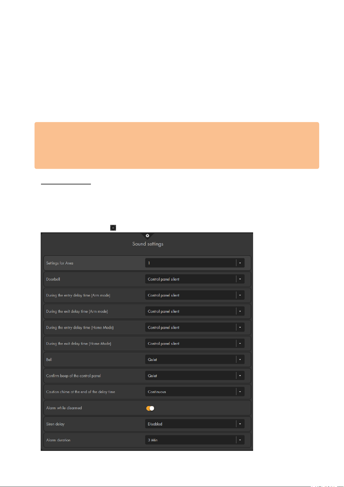
Personal threat
Panic and emergency alarm
Medical emergency
Gas, CO, medical alarm
External siren(s)
If additional sirens are connected to the alarm panel, you can specify, in which cases they
shall sound an alarm. If several external sirens are connected, you cannot configure them
individually – either all external sirens sound an alarm or none of them does.
Similar to the internal siren, the following options are available for selection:
Burglary, fire/emergency exit, water, personal threat, medical emergency.
Please note:
An installed wireless relay (#12014) reacts similarly to an external siren. If the alarm for
external sirens in case of burglaries is disabled, then the wireless relay will likewise not
be activated in case of a burglary alarm.
Sound settings
In this menu you can control the internal siren of the alarm panel, as well as, external
sirens. However, you can only adjust the volume of the internal siren. You can only mute
external sirens (“All sirens off”) in this menu – otherwise their volume is not adjustable.
Additional settings for external sirens can be found in the menu “Alarm system “ “Siren
settings” Sirens” .
98
Page 99

Setting for area
Set for which of the two areas you want to adjust the settings.
Doorbell
Set the volume of the doorbell.
During the entry delay time (Arm mode)
Set the volume for the entry delay while the alarm panel is in arm mode.
During the exit delay time (Arm mode)
Set the volume for the exit delay when you activate the arm mode.
During the entry delay time (Home mode)
Set the volume for the entry delay while the alarm panel is in home mode.
During the exit delay time (Home mode)
Set the volume for the exit delay when you activate the home mode.
Bell
Set the volume of the warning sound of the alarm panel in case of an error (see
chapter “System” “Status” “Panel”). External sirens do not sound this
warning sound.
Confirmation beep of the alarm panel
Allows you to set the last confirmation sound of the internal siren of the alarm
panel.
Caution chime at the end of the delay time
Set for how many seconds of the entry delay time you want to be notified before
the delay time ends.
Example:
If you enter 5 seconds, a warning sound (countdown) will start to sound only for
the last 5 seconds before the entry delay ends. If you activate Continuous, the
warning sound will sound for the entire duration of the entry delay.
Siren delay
If this setting is enabled, the internal and external sirens will sound the alarm
delayed (burglar alarm follow or instant). The delay does not affect smoke alarm,
water alarm, entrance delay, etc..
Alarm while disarmed
This option is “On” by default. If this setting is active, the internal siren of the alarm
panel, as well as, all connected sirens sound an acoustic alarm even if the alarm
panel is disarmed. This includes every alarm that is not silent, e.g. panic alarm or
24h smoke alarm. You can see which sensors are set to 24h via “Sensors” “List”
“Alarm overview.” If you only want to be informed about an alarm while the alarm
panel is disarmed by e-mail, text message, contact ID, but not in an acoustic way,
set the option to “Off.”
Alarm duration
This option refers to the alarm duration of all connected sirens. You can specify
the maximum alarm duration. If the alarm panel is disarmed again, the acoustic
alarm is switched off.
Note:
If the alarm duration of an external siren is set shorter with the DIP switches
(SW3+4, if available), as described in the according siren’s manual, then, the
audio alarm of the external siren will end early. Vice versa, the alarm duration of
an external siren will end early if the alarm duration in the alarm panel is set for a
shorter period than the DIP switches (SW3+4). If the alarm duration is “disabled,”
all added sirens remain off.
99
Page 100
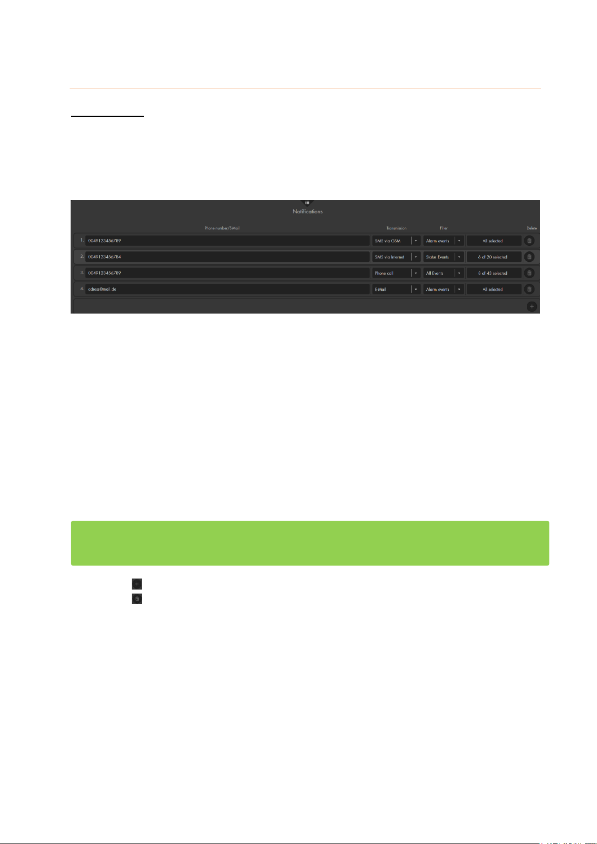
Report
Notifications
In this menu, you can define whether the alarm panel shall notify you in case of alarms,
status changes or all events. You can select between the options to send text messages
via GSM or via the internet, to be notified via a phone call (via SIM card), and via e-mail.
To reduce the risk of failures, you can set tup to 25 receivers in this menu
To use the different notification methods, you need either, a SIM card (with deactivated
PIN code), an internet connection and a account with one of the supported SMS clients,
or an internet connection and an e-mail address.
You can specify 20 recipients. To use the function “via internet,” you need to open a an
account with one of the provided internet SMS providers (see chapter “GSM & SMS”) or
insert a SIM card without SIM lock (PIN query deactivated) and with sufficient credit for
the delivery via the GSM module. For further information, refer to chapter “Network”
“GSM & SMS.”
Please note:
To use these notification methods, make sure to set them up first. This can be done
in the menus “Settings” “E-Mailaccount”, “Settings” “SMS account”, and
“Settings” “SIM card”.
The XT1 Plus does not feature a GSM module. Hence, you cannot use the method
“SMS via GSM” and “Phone call”. Likewise, the menu “Settings” “SIM card” does
not exist.
Use to create a new notification.
Use to delete a notification.
o Phone number / E-mail
Enter a valid phone number to receive a SMS or phone call. If this is the
number of a security firm, enter your account number before that (e.g.
1234@0177123456).
If you want to send an e-mail, enter the e-mail address of the receiver.
o Transmission
“SMS via GSM” (SIM card) send an SMS via the GSM module.
“SMS via Internet” (network + internet connection) send an SMS
via one of the supported internet SMS providers.
“Phone call” (SIM card) phone call via the GSM module.
“E-Mail” (network + internet connection) send an e-mail.
o Filter
You can choose from a drop-down menu whether the alarm panel is to notify
100
 Loading...