

Page 1
MBR2520(F)CT~MBR25200(F)CT
Features
The plastic package carries Underwriters Laboratory
Flammability Classification 94V-0
Construction utilizes void-free molded plastic technique
Low reverse leakage
High forward surge current capability
High temperature soldering guaranteed:
250°C,MAX. for 10 seconds
Mechanical Data
Case
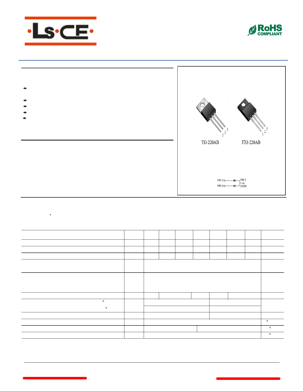
: (I)TO-220AB molded plastic body
Terminals: Solder plated, solderable per MIL-STD-750, Method 2026
Polarity
Mounting Position: Any
Maximum Ratings And Electrical Characteristics
Ratings at 25 C ambient temperature unless otherwise specified.
for capacitive load current derate by 20%.
: As marked
Single phase half-wave 60Hz,resistive or inductive load,
25.0Amp Schottky Barrier Rectifiers
SYMBOLS
Maximum repetitive peak reverse voltage
Maximum RMS voltage
Maximum DC blocking voltage
Maximum average forward rectified current
(see fig.1)
Peak forward surge current
8.3ms single half sine-wave superimposed on
rated load (JEDEC Method)
Maximum instantaneous forward voltage at 12.5A
Maximum DC reverse current TA=25 C
at rated DC blocking voltage TA=100 C
Typical junction capacitance (NOTE 1)
Typical thermal resistance (NOTE 2)
Operating junction temperature range
Storage temperature range
Note:1.Measured at 1MHz and applied reverse voltage of 4.0V D.C.
VRRM
VRMS
VDC
I(AV)
IFSM
VF
CJ
RθJC
TJ
TSTG
MBR
2520(F)CT
20
14
20
0.55
IR
MBR
2540(F)CT
40
28
40
-55 to +125 -55 to +150
MBR
2545(F)CT
45
32
45
0.60
0.15
40.0 20.0
580
MBR
2560(F)CT
60
42
60
0.70
-55 to +150
MBR
25100(F)CT
25.0
200.0
0.85
23
2.Thermal resistance from junction to case
www.
cnelectr
.net
100
70
100
25150(F)CT
0.1
180
MBR
150
105
150
MBR
25200(F)CT
140
0.95
200
200
UNITS
VOLTS
VOLTS
VOLTS
Amps
Amps
Volts
mA
pF
C/W
C
C
Page 2
MBR2520(F)CT~MBR25200(F)CT
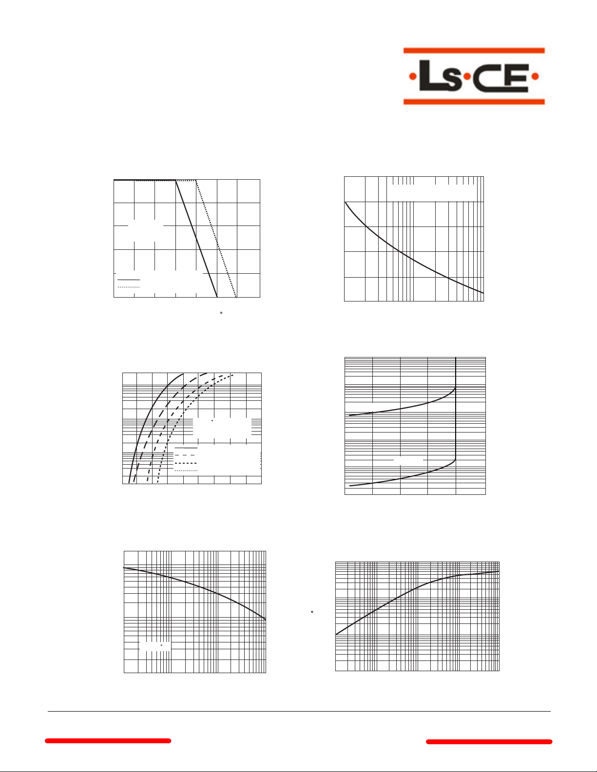
Ratings And Characteristic Curves
FIG. 1- FORWARD CURRENT DERATING CURVE
25.0
20.0
15.0
AMPERES
10.0
AVERAGE FORWARD RECTIFIED CURRENT,
CURRENT,AMPERES
INSTANTANEOUS FORWARD
Single Phase
Half Wave 60Hz
Resistive or
inductive Load
5.0
0
0 25 50 75 100 125 150 175
0.2
0.02
MBR2520(F)CT-MBR2060(F)CT
MBR25100(F)CT-MBR25200(F)CT
AMBIENT TEMPERATURE, C
FIG. 3-TYPICAL INSTANTANEOUS FORWARD
40
20
2
0.2 0.4 0.6 0.8 1.0 1.1
INSTANTANEOUS FORWARD VOLTAGE,
CHARACTERISTICS
TJ=25 C
PULSE WIDTH=300
1%DUTY CYCLE
MBR2520(F)CT-MBR2545(F)CT
MBR2560(F)CT
MBR25100(F)CT
MBR25150(F)CT-MBR25200(F)CT
VOLTS
FIG. 2-MAXIMUM NON-REPETITIVE PEAK FORWARD
250
200
150
AMPERES
100
50
PEAK FORWARD SURGE CURRENT,
0
1 10 100
FIG. 4-TYPICAL REVERSE CHARACTERISTICS
100
10
1.0
µs
0.1
MILAMPERES
0.01
INSTANTANEOUS REVERSE CURRENT,
0.001
0 30 60 90 120 150
PERCENT OF PEAK REVERSE VOLTAGE,%
SURGE CURRENT
8.3ms SINGLE HALF SINE-WAVE
(JEDEC Method)
NUMBER OF CYCLES AT 60 Hz
TJ=100 °C
TJ=25 °C
FIG. 5-TYPICAL JUNCTION CAPACITANCE FIG. 6-TYPICAL TRANSIENT THERMAL IMPEDANCE
2000
1000
100
JUNCTION CAPACITANCE, pF
10
TJ=25 C
0.1 1.0 10 100
REVERSE VOLTAGE,VOLTS
www.
cnelectr
100
10
C/W
1
TRANSIENT THERMAL IMPEDANCE,
0.1
0.01 0.1 1 10 100
t,PULSE DURATION,sec.
.net
Page 3
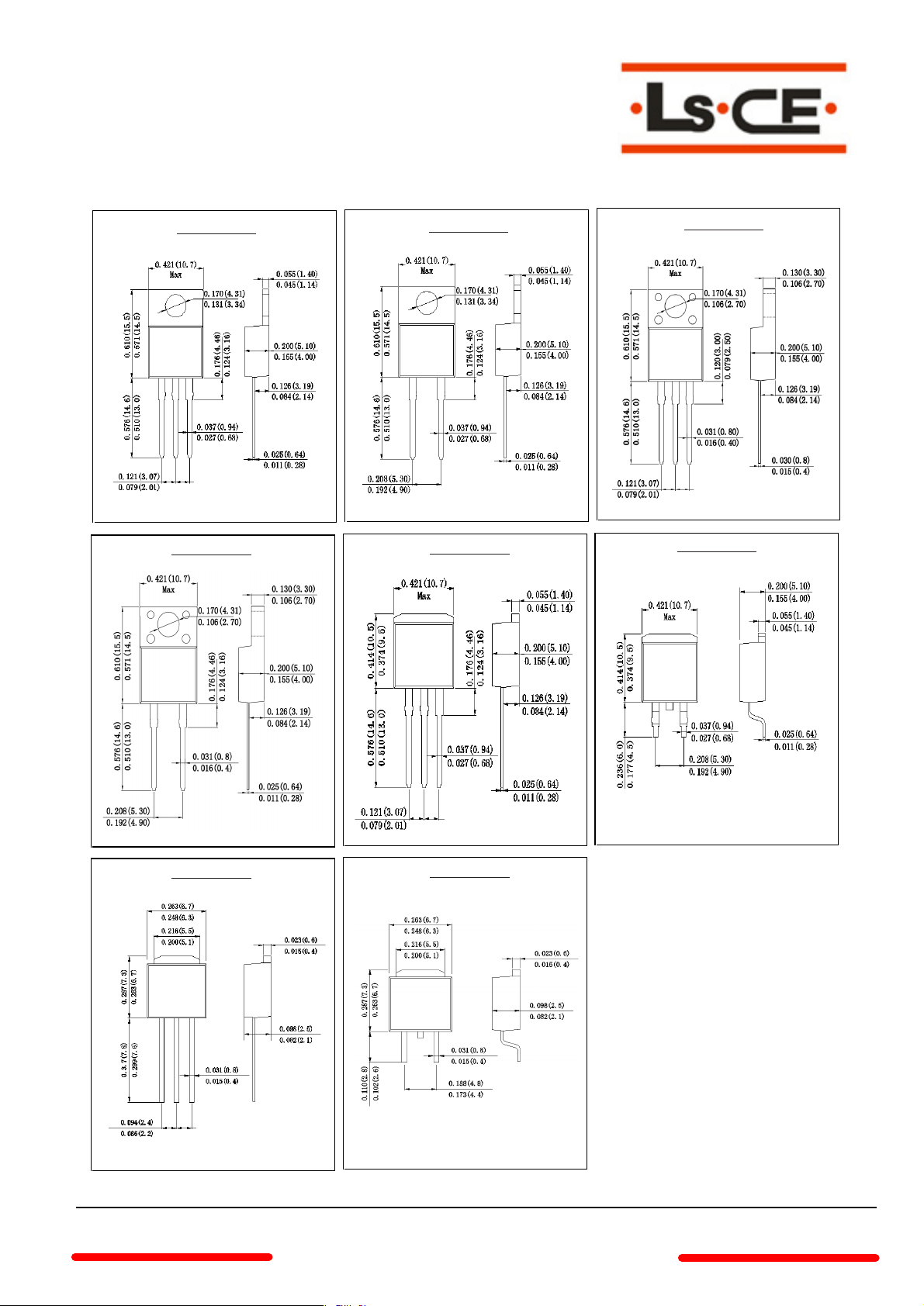
Outline Drawing
All dimensions in inches and (millimeters)
TO-220AB
ITO-220AC
TO-220AC
TO-262
ITO-220AB
TO-263
TO-251
www.
TO-252
cnelectr
.net
 Loading...