

Page 1
Mounting Instructions
Decentralized Ventilation System with Heat Recovery Type
e² mini
- Please pass on to User-
Contents Page:
About these instructions, Safety instructions, Technical data, Disposal 1
Dimension drawings, Mounting position 2
Scope of application, Shipping units 3
Assembly: Mounting tube, Outer grille 4
Assembly: Electrical installation and Electrical connection 5
Assembly: Heat exchanger unit and interior screen 6
Filter change, Cleaning, Additional and Spare parts 7
About these Instructions
Read these instructions carefully and completely before executing assembly work! General safety
instructions and the safety symbols with respective notes in text form must be observed.
These instructions are to be passed on to the user after completing assembly work (tenant, own-
er, building administration etc.).
Symbols in these instructions
This symbol warns of a risk of injury.
This symbol warns of a risk of injury from electricity
Safety Instructions
Caution! All terminals must be completely disconnected from the power supply before com-
mencing assembly work! The fan is insulated pursuant to Protection Class II, connection protection does not apply!
Attention! Electrical connections must be carried out by authorized qualified staff in accordance with applicable VDE 0100!
Attention! This device must not be operated by children or persons (filter change/cleaning)
who are not able to operate it safely on account of their physical, sensory or mental capacity or
due to their inexperience or lack of skills. Children must be supervised to ensure they do not
play with the device.
Technical Data
Supply voltage: 230 VAC 50 Hz
Device voltage: 12 VDC SELV
Protection Class: IP 22
Flow rate: 5m³/h; 10m³/h; 20m³/h
Disposal
Dispose of packaging correctly sorted. If you wish to dispose of the device, observe applicable conditions. Your local disposal center will provide relevant information.
1
Page 2
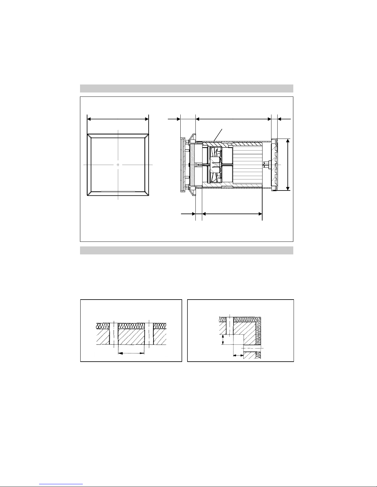
Dimension drawing (all dimensions in mm)
Installation Position
2
1m
Decentralized fans with heat recovery of the type e² mini only function in pairs in alternating operation.
One device operates for 50 s in supply air mode, the other for 50 s in exhaust air mode at the respective flow rate set. After this, the direction of air flow is changed. This ensures that the total flow rate
supplied is the same as the total air flow ejected. If a push-pull device pair is installed and operated in
two different rooms in the apartment, a sufficient volume of air must always be ensured between these
two rooms via adequately large dimensioned overflow air passages.
Minimum distance recommended when installing a device pair in one wall:
Minimum distance recommended when installing a device pair at a right angle:
1m
1m
□136 34 min. 167 14
15 133
Ø115
Assembly tube DI 100 mm,
DA 104 mm
Dimensions in mm
Do not position the device above sensitive furniture, surfaces or pictures, the wall beneath the device
should remain ‚unused‘.
Do not position the device above or near room thermostats.
Page 3
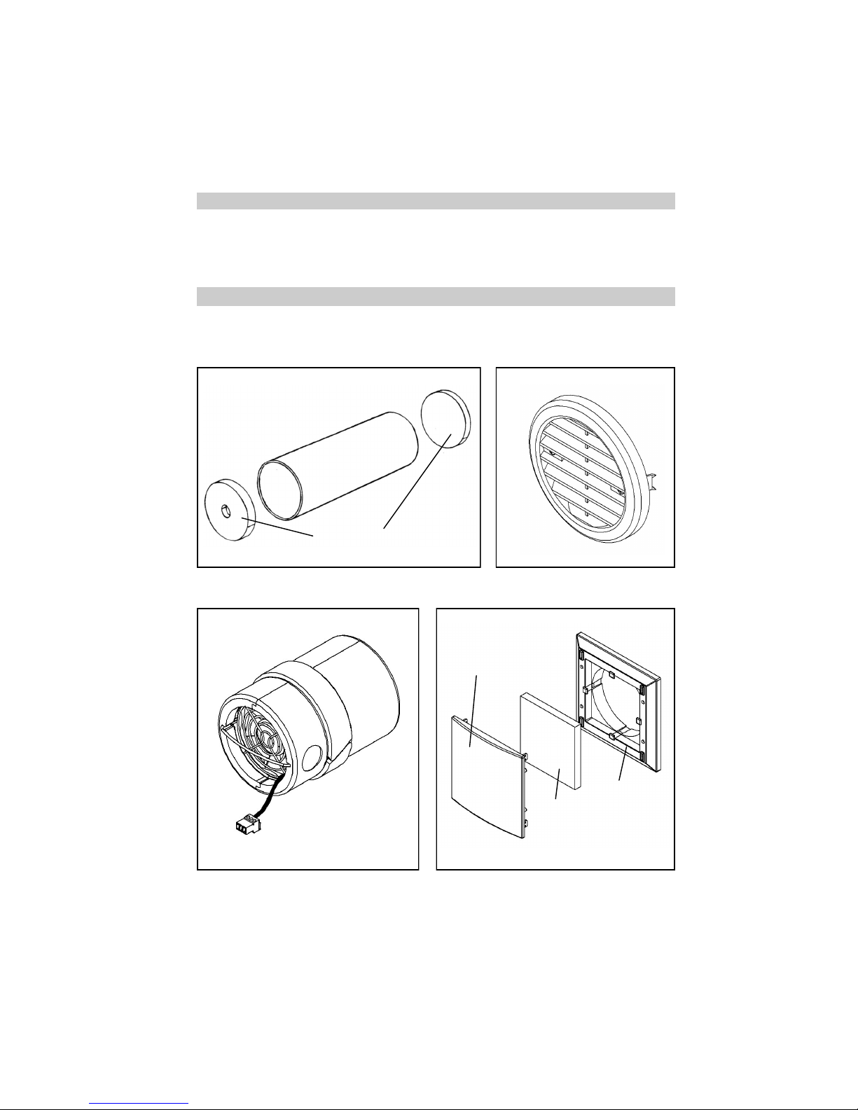
Shipment units
Check the delivery with regard to completeness and perfect condition!
Assembly tube Outer grille
Insert e² mini Interior screen 2/IBM
3
Tube DI 100 mm
Plaster protective
Filter
Design screen
Cover
frame
Scope of application
Temperature range: - 15°C to + 40°C
Can be used at a relative humidity of up to 65% inside the apartment. Low condensate formation
may occur during the heating period. If limits are exceeded, switch off the device and close the interior screen. Ensure supply of fresh air by opening the window.
Page 4
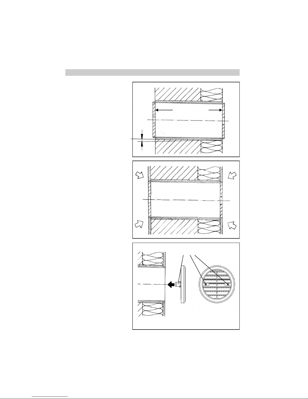
Other outer grilles available on request!
Assembly—Assembly Tube and Outer Grille
Prepare wall cavities for the assembly tube (via core bore hole, drill bit
Ø106 mm). If necessary, shorten the
tube to the required installation
length. Make sure there is a protrusion of the tube on both sides to
bridge the plaster thickness (after
plastering, the tube must be flush
with the plaster). Insert the tube and
seal it all round (Assembly adhesive
Order No. 038 733).
Apply the inside and outside plaster.
In the case of an outside closure to
be plastered, first replace the plaster
protective cover with the outside
closure.
Remove the outside plaster protective cover. Mount the outer grille
using the integrated claws (tighten
the screws). The solid plastic outside covers provided by Lunos ensure high resistance to driving rain
and can be used in the Stress
Group III pursuant to DIN 4108-3
(2012-04). Metal or metal-coated
covers can be used in Stress Group
I pursuant to DIN 4108-3 (2012-04).
In the case of buildings exposed to
wind or the risk of strong winds and
rain to the outside covers, further
measures of weather protection may
be required.
4
①
②
➂
inside
inside
outside
outside
Plaster protective
Tighten the claws with screws
3 mm
Page 5
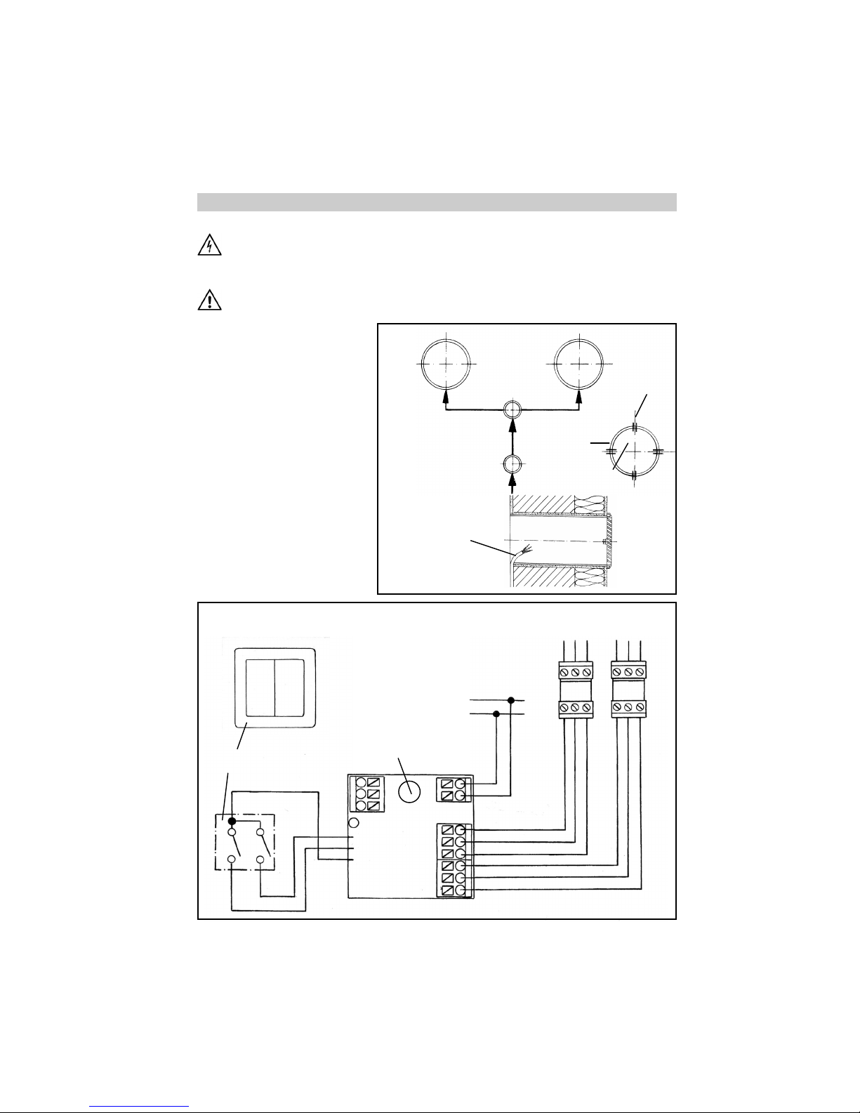
Assembly – Electrical Installation and Electrical Connection
Caution! All assembly work on the fan must only be carried out when power has been disconnected from all
terminals!
Make sure all connection lines are de-energized before connecting the fan to the power supply !
(disconnection from power supply with at least 3 mm contact opening, e.g. all-pole circuit-breaker)
Each circuit connected to the ventilation system must be fitted with residual current protection (e.g. a RCD
switch)! Electrical connections must be carried out by qualified staff only!
Additional installations and electrical components in this ventilation system are not admissible!!
Triggering can be made via the
universal control 5/UNI and the
added feature control TAC. Respective installation instructions
apply accordingly.
Select the position of the switch.
Slit the cable ducts (power cable +
cable to device pairs) and the
tubes (2 cm deep). Install the power cable (e.g. 3 x 1.5 mm² ) and
the cables to the device pairs (e.g.
3 x 0.75 mm² ). Prepare the cables
to the device pairs in the tube.
Circuit and switches are connected
in accordance with the wiring diagram below.
5
➃
Power
Switch
Device 1
Out/In
Device 2
In/Out
horizontal
vertical
also slit tubes
for cables
only slit
tubes in
these four
sections
Joint box
Safety Instructions
Device cable prepared in tube
I III II
0
Important! Set the
coding switches to
the functions required for e² mini
(refer to Installation
Instructions E 148).
Deviating coding
switch settings are
inadmissible and
result in malfunctions!
Series switch 5/W2U
Front view
Universal
control
5/UNI
grey
red
black
W1 W2
+ 12V
-
rt bl li rt bl li
Device (e)1 Device (e)2
Out/In In/Out
5
Page 6
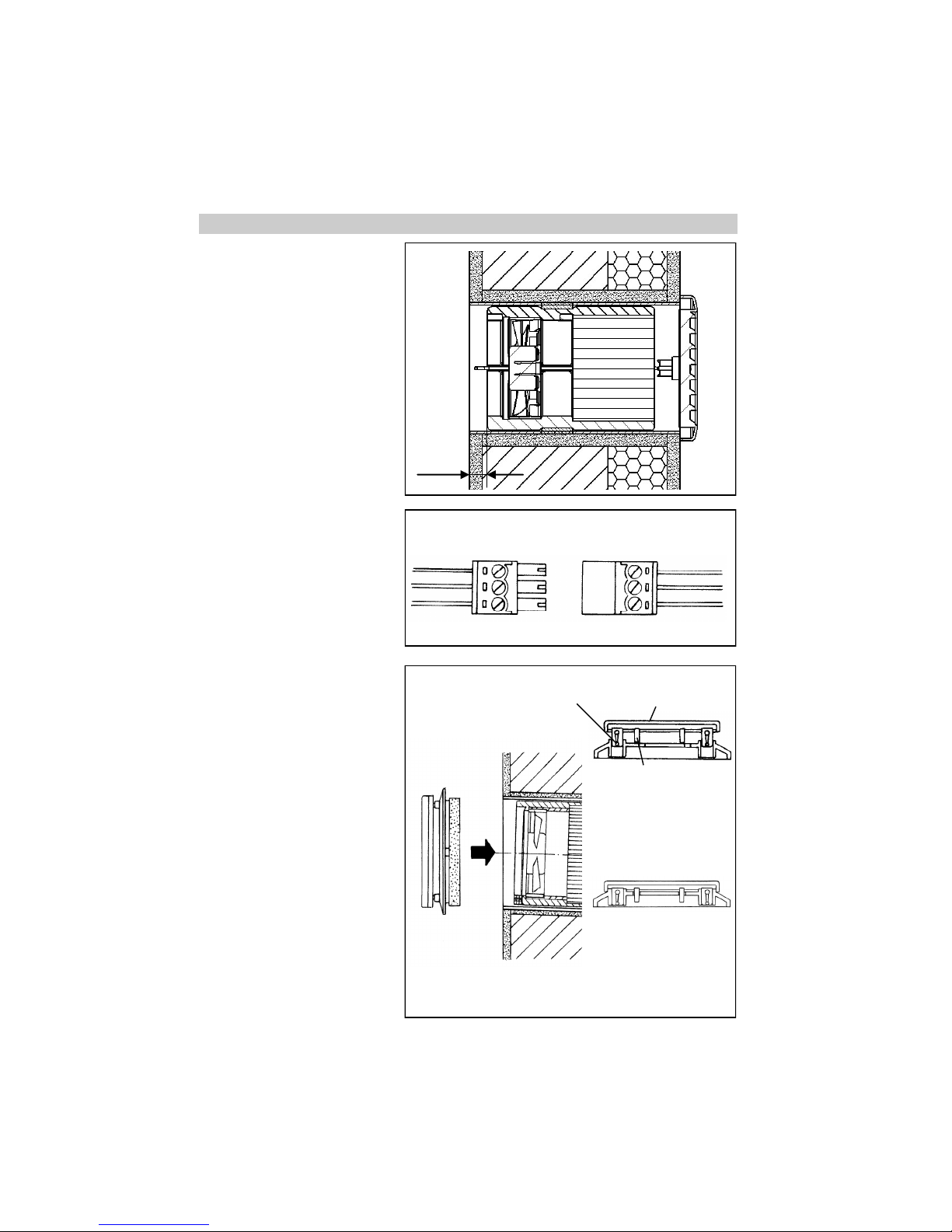
Assembly – Heat exchanger unit and Interior screen
Remove the inside plaster protective cover and insert the heat exchanger unit into the assembly
tube, observe 15 mm distance.
Using the loop on the inside of the
heat exchanger unit, the unit can be
adjusted by pulling out, if required.
Connect the cable to the connector
and install into the tube in front of
the motor.
6
⑦
Cable Motor cable
red
blue
purple
⑧
Insert inside closure with filter, snap
the interior screen in in the Open
position!
Finished!
⑨
15 mm
„Open position“
„Closed position“
Catch lock
Fixing pin
Design screen
- Catch locks snapped in
- Fixing pins in front of
cover frame
- Design screen turned
180° compared to Open
position.
- Fixing pins sunk into the
bore holes of the cover
frame.
Page 7
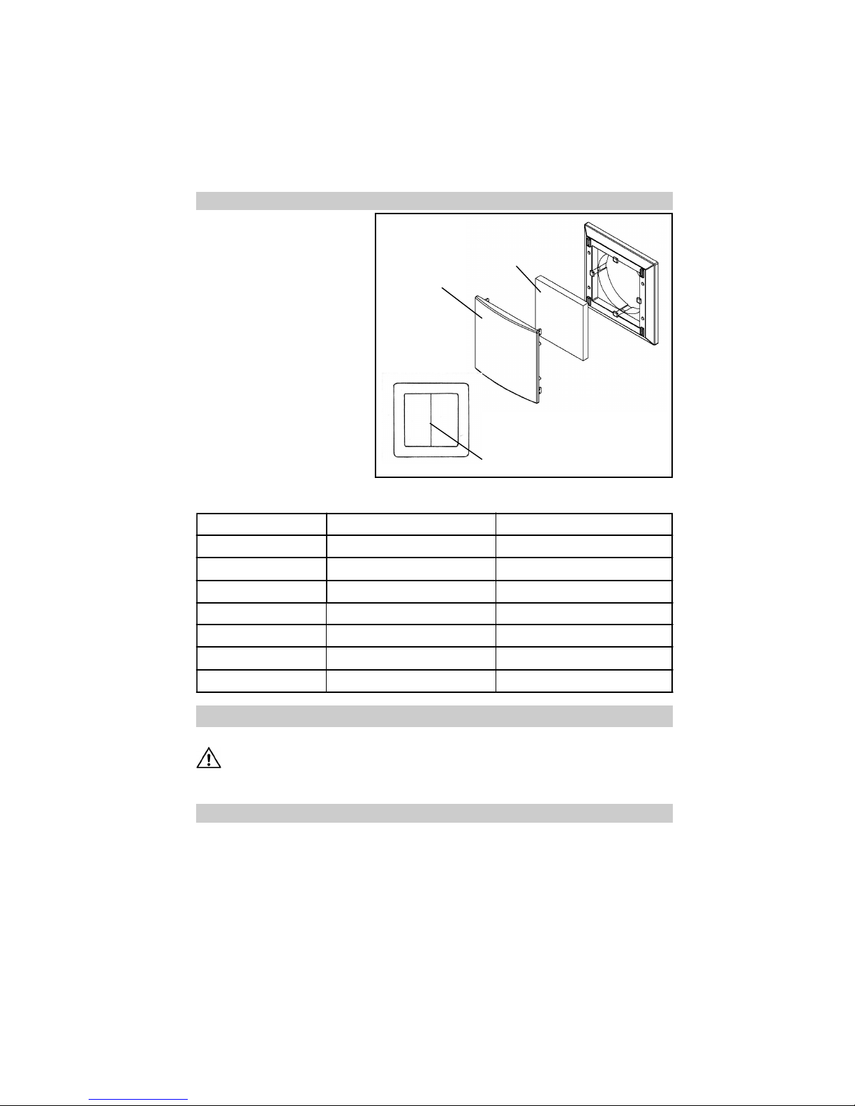
Filter change date planned filter change Filter type used
Please record the filter changes made below:
Filter Change
Cleaning
Wipe the interior screen and cover frame with a dry, soft cloth when required.
Filter change and cleaning must not be carried out by children and persons not able to execute
such work due to their physical, sensory or mental capacity, or due to their inexperience or lack of
skills.
Additional / Spare parts
The filter change display indicates
when a filter is dirty. In connection
with the universal control, a red
LED lights up continuously beneath
the switch.
Remove the design screen, remove the filter, install the new or
cleaned filter (cleaning of the filter
can be executed e.g. in the dishwasher), put the design screen
back on.
The vents must not be obstructed
or covered.
Reset the filter change display by
rocking the rocker switch W1 once.
Functionality of the filter change
display in connection with the TAC
and LUNOS-KNX control is described in the respective instructions.
I III II
LED lights up beneath switch
Design screen
Filter
Replacement filter Filter Class G3; pack of 3 Type 9/FB3R Order No.: 037 176
Page 8
E 173/ 06.14
Deutschland
LUNOS Lüftungstechnik GmbH Tel.: 0 30 / 36 20 01 - 0
für Raumluftsysteme Fax: 0 30 / 36 20 01 - 89
Wilhelmstr. 31 email: [email protected]
13593 Berlin Internet: http://www.lunos.de
Notes
 Loading...