

Page 1
DE Einbauanleitung
Dezentrales Lüftungssystem
mit Wärmerückgewinnung
Typ ego
- Bitte an den Nutzer weiterleiten -
EN Installation Manual
Decentralised Ventilation
System with Heat Recovery
Type ego
- Please pass on to user -
Page 2
2
237 mm 257 mm
217 mm
63 mm 300* bis 500**mm 63 mm
1
(C)
(D)
30 cm 25 cm
30 cm
2
(E)
(F)
3
(G)
(I)
(H
(J)
(K)
(L)
(L)
4
(A) (B)
Page 3
3
(M)
(N
?
(O)
(P
(Q)
5
6
7
8
4,6 cm
3,9 cm
(R)
(S)
9
(T) (U) (V)
(W)
10
OBEN/TOP
(Y)
(X)
11
(Y)
12
(A)
(B)
(A)
(B)
(F)
3 mm
Ø 6 mm
Page 4
4
(Z)
(Y)
13
+ - S1 + - S2
(Y) (Z)
14
(I)
(G)
(H)
(Z1)
(J)
15
(N)
(Z2)
16
(L)
(M)
(N)
17
(G)
(J)
18
Page 5
5
Zu dieser Anleitung, Sicherheitshinweise, Technische Daten, Entsorgen 5
Maßbild, Einbauposition, Einsatzbereich 6
Versandeinheiten 6
Montage: Montagerohr 6
Montage: elektrische Installation und elektrischer Anschluss 7
Montage: Lüftereinsatz, Innenraumblende 7
Montage Außenblende 7
Verschluss der Innenblende 8
Filterwechsel, Sommerlüften, Reinigung, Zusatz- und Austauschteile 8
Lesen Sie vor Montage diese Anleitung sorgfältig und vollständig durch! Beachten Sie unbedingt
die allgemeinen Sicherheitshinweise und die Sicherheitssymbole mit Hinweisen im Text.
Diese Anleitung ist nach Abschluss der Montage an den Nutzer (Mieter, Eigentümer, Hausverwal-
tung usw.) weiterzugeben.
Zeichen in dieser Anleitung
Dieses Zeichen warnt Sie vor Verletzungsgefahren.
Dieses Zeichen warnt Sie vor Verletzungsgefahr durch Elektrizität
Vorsicht! Jede Montagearbeit am Lüftungsgerät darf nur bei allpolig abgetrennter Netzspannung erfolgen! Das Lüftungsgerät ist schutzisoliert nach Schutzklasse II, der Schutzleiteranschluss entfällt!
Achtung! Der elektrische Anschluss darf nur von autorisiertem Fachpersonal und nach
gültiger VDE 0100 vorgenommen werden!
Achtung! Dieses Gerät darf nicht von Kindern und Personen (Filterwechsel/Reinigung)
bedient werden, die aufgrund ihrer physischen, sensorischen oder geistigen Fähigkeiten oder
ihrer Unerfahrenheit oder Unkenntnis nicht in der Lage sind, es sicher zu bedienen. Kinder
sollten beaufsichtigt werden, um sicherzustellen, dass sie nicht mit dem Gerät spielen.
Versorgungsspannung: 230 VAC 50 Hz
Gerätespannung: 12 VDC SELV
Schutzart: IP 22
Volumenstrom: 5; 10; 15; 20 m³/h im Reversierbetrieb, 45 m³/h im Abluftbetrieb
Entsorgen Sie die Verpackung sortenrein. Wenn Sie sich vom Gerät trennen möchten, entsorgen Sie es zu den aktuellen Bestimmungen. Auskunft erteilt die kommunale Stelle.
Einbauanleitung DE
Sicherheitshinweise
Inhalt Seite:
Zu dieser Anleitung
Entsorgen
Technische Daten
Page 6

6
(A) innen; (B) außen;
* minimal ** größere Längen möglich
Im ego arbeiten zwei Ventilatoren immer in entgegen gesetzter Richtung und sorgen so gleichzeitig
für Zu- und Abluft. Für eine ungehinderte Luftströmung ohne unzulässige Durchmischung von Zu–
und Abluft müssen Mindestabstände zur Wand und zu umliegenden Bauteilen eingehalten werden!
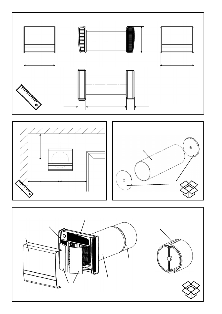
Bild 2: Mindestabstände zur Wand und zu umliegenden Bauteilen
((C) Wand; (D) Fenster)
Temperatureinsatzbereich: - 15°C bis + 40°C
Einsetzbar bei einer relativen Luftfeuchte bis 65% im Innenraumbereich (nicht kondensierend). Bei
Überschreitung der Einsatzgrenzen Gerät ausschalten und Innenblende verschließen. Frischluftzufuhr durch Fensterlüftung sicherstellen.
Überprüfen Sie die Lieferung auf Vollständigkeit und einwandfreien Zustand!
Bild 3: Montagerohr
((E) Rohr DA 160 mm; (F) Putzschutzdeckel)
Bild 4: ego-Einschub
((G) Deckel; (H) Innengehäuse-Unterteil; (I) Filter (2x); (J) Verschlusselement (2x); (K) Wär-
metauschereinheit mit Motoren; (L) EPP-Adapter: 2 Stück an der Wärmetauschereinheit
montiert bzw. optional als Zusatzteil)
Bild 5: Außenblende Typ 1/EGA Bestell -Nr.: 40019
((M) Deckel; (N) Außenblende-Unterteil))
+ Schraubenzubehör
Bild 6: Wetterschutzhaube Typen:
1/HWE-2 weiß Bestell-Nr.: 40107
1/HAZ-2 anthrazit Bestell-Nr.: 40108
((O) Abdeckung; (P) Rahmen; (Q) Verbindungsschrauben)
+ Schraubenzubehör
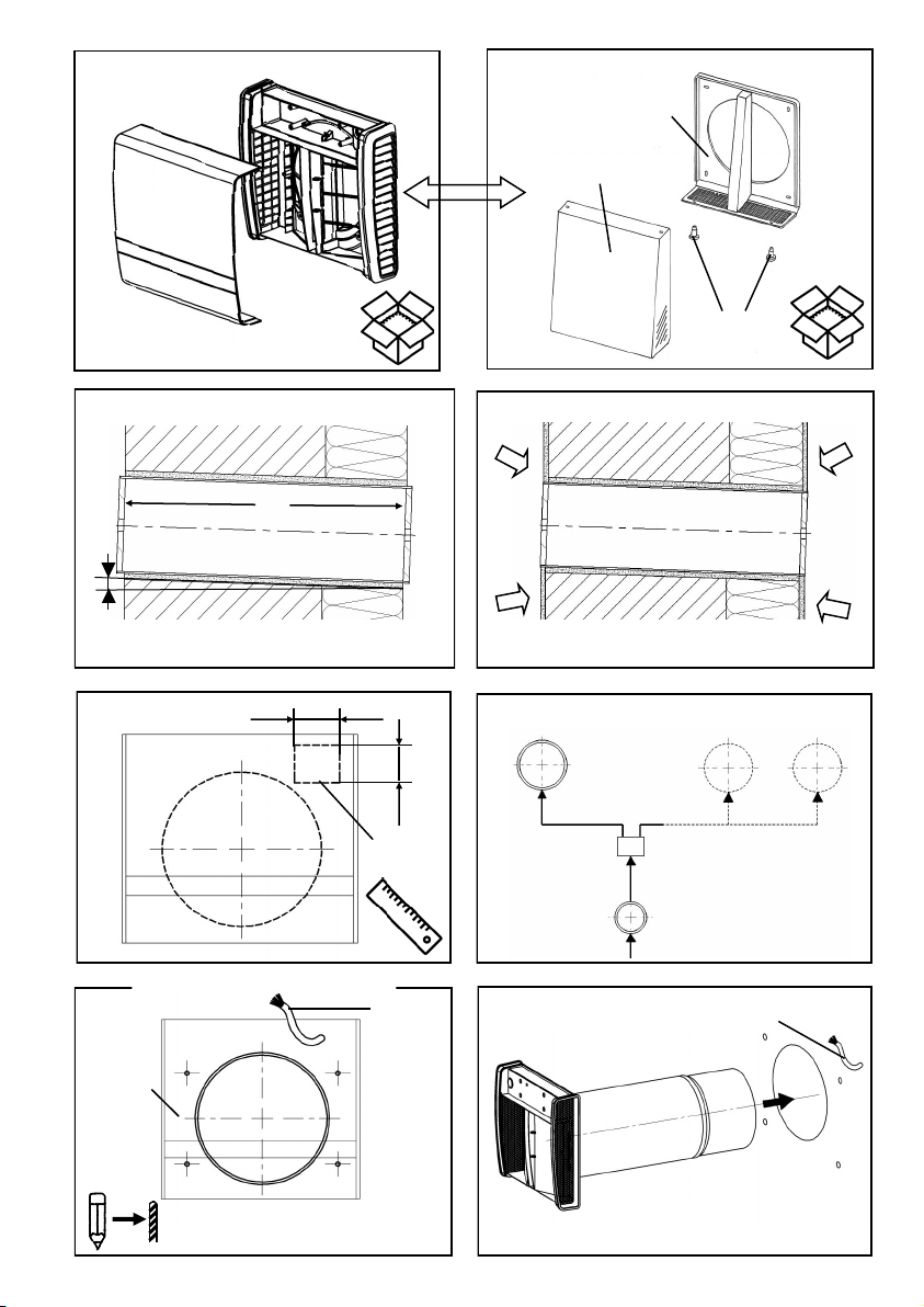
Bild 7: Schaffen Sie di e Wandöffnungen für die Montagerohre (z.B. mittels Kernbohrung,
Bohrkrone Ø162 mm). Kürzen Sie ggf. das Rohr auf die gewünschte Einbaulänge.
Achten Sie dabei auf einen eventuellen beidseitigen Überstand des Rohres zur Über-
brückung der Putzdicken (das Rohr muss nach dem Einputzen bündig mit dem Putz
abschließen). Setzen Sie das Rohr ein und dichten Sie es umlaufend ab (Montagekleber
Best.-Nr. 38733).
((A) innen; (B) außen; (F) Putzschutzdeckel)
Bild 8: Bringen Sie den Innen und Außenputz an. ((A) innen; (B) außen)
Bild 9: Stellen Sie das Kabel für den Geräteanschluss im gekennzeichneten Bereich bereit
z.B. J-Y (ST)Y4x2x0,8).Kabellänge ca. 100 bis 120 mm. Nutzen Sie dazu die Bohrschablo-
ne! ((R) Kernbohrung bzw. Wandeinbaurohr; (S) Bereich für Gerätekabel)
Maßbild (Bild 1)
Einsatzbereich
Montage - Montagerohr (Bild 7 bis 9)
Versandeinheiten (Bilder 3 bis 6)
Einbauposition (Bild 2)
Page 7
7
Vorsicht! Jede Montagearbeit am Lüftungsgerät darf nur bei allpolig abgetrennter Netzspannung erfolgen!
Machen Sie vor Anschluss des Lüftungsgerätes an die Netzspannung alle Anschlussleitungen
spannungsfrei! (Abtrennung vom Netz mit mindestens 3 mm Kontaktöffnung, z.B. allpolig trennende elektr. Sicherung).
Jeder zu diesem Lüftungssystem gehörende Stromkreis muss mit einem Fehlerstromschutz
(z.B. FI-Schalter) ausgestattet sein!
Elektrischer Anschluss nur durch Fachmann! Zusätzliche Installationen und elektrische Bauelemente sind nicht zulässig!
Sicherheitshinweise
Bild 10: Die Ansteuerung kann über verschiedene von LUNOS angebotene Steuerungen er -
folgen. Hierzu gelten die entsprechenden Einbauanleitungen.
Wählen Sie die Position des Schalters. Schlitzen Sie die Kabelkanäle. Verlegen Sie das
Kabel zum Schalter bei Unterbringung des Netzteils unter dem Schalter z.B. 3x 1,5mm²,
ansonsten genügt ein geringerer Querschnitt z.B. J-Y(ST)Y 4 x 2 x 0,8) und die Kabel zu
den Geräten ( z.B. J-Y(ST)Y 4 x 2 x 0,8).
((T) Gerät 1; (U) weitere Geräte, (V) Steuerung; (W) Schalter)
Bild 11: Bohren Sie mit Hilfe der Bohrschablone die Befestigungsbohrungen für die Innen -
raumblende (Bohrdurchmesser: 6mm) und setzen Sie die beiliegenden Dübel ein.
Hinweis: Beachten Sie die Aufschrift „OBEN“, eine abweichende Einbaulage ist aus
strömungstechnischen Gründen unzulässig!
((X) Bohrschablone; (Y) Geräteanschlußkabel)
Bild 12: Entfernen Sie die Putzschutzdeckel. Kürzen Sie den EPP- Adapter auf die Länge des
Montagerohres. Bei Rohrlängen über 500 mm können zusätzliche Adapterstücke montiert
werden!
Führen Sie das Lüftungsgerät (Innengehäuse-Unterteil, Wärmetauschereinheit und EPP-
Adapter) in das Montagerohr ein!
((Y) Geräteanschlußkabel)
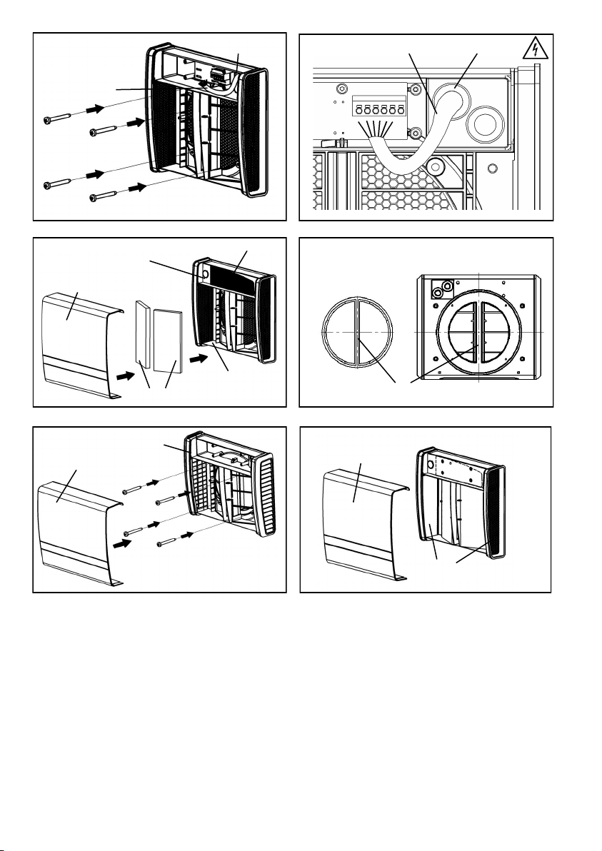
Bild 13: Führen Sie das Anschlusskabel (Y) durch eine der Tüllen (Z) des Innengehäuse-
Unterteils in den Bereich für den elektrischen Anschluss! Befestigen Sie das Innengehäuse-
Unterteil mit den beiliegenden Schrauben an der Wand!
Bild 14: Schließen Sie das Lüftungsgerät an! ((Y) Geräteanschlusskabel; (Z) Tülle)
Bild 15: Montieren Sie den Deckel für den elektrischen Anschlussbereich (Z1) und legen Sie
darüber die Verschlusselemente (J) ein!
Setzen Sie die Filter (I) ein und rasten Sie den Deckel (G) ein!
((H) Innengehäuse-Unterteil)
Bild 16: Bohren Sie mit Hilfe der Bohrschablone ((X) -siehe Bild 11) die Befestigungsbohrungen
und setzen Sie bauseits (dem Untergrund entsprechend )zu stellende Dübel ein!
Setzen Sie das Außenblenden-Unterteil (N) auf den im Rohr befindlichen EPP-Adapter (N)!
Nur senkrechte Lage der Mittelstege (Z2) zulässig!
Bild 17: Befestigen Sie das Außenblenden-Unterteil (N) mit den beiliegenden Schrauben!
Setzen Sie den Deckel (M) auf!
Hinweis: Den alternativ zu montierenden Wetterschutzhauben (Bild 6) liegt eine gesonderte
Einbauanleitung bei!
Montage – Außenblende 1/EGA (Bilder 16 und 17)
Montage – Montage Lüftereinsatz, Innenraumblende (Bilder 11 bis 15)
Montage – Elektrische Installation und elektrischer Anschluss (Bild 10)
Page 8
8
Bild 18: Mit den magnetischen Verschlusselementen (J) kann im Bedarfsfall die Innenblende
verschlossen werden:
Verschlusselemente wie dargestellt mit der roten Seite nach außen von Innen vor die Lüftungsgitter
legen!
Deckel (G) aufsetzen!
Ein verschmutzter Filter wird durch die Filterwechselanzeige signalisiert. In welcher Weise dies erfolgt, entnehmen Sie bitte der Beschreibung der von Ihnen verwendeten Steuerung.
Deckel (G) abnehmen, Filter (I) entnehmen, neuen oder gereinigten Filter einlegen (die Reinigung
des Filters kann z.B. mit dem Geschirrspüler erfolgen), Deckel aufsetzen.
Die Lüftungsöffnungen dürfen nicht zugestellt oder verdeckt werden.
Bitte notieren Sie hier die von Ihnen durchgeführten Filterwechsel:
Wischen Sie bei Bedarf Innenraumblende und Abdeckrahmen mit einem trockenen weichen
Tuch ab.
Filterwechsel und Reinigung dürfen nicht von Kindern und Personen durchgeführt werden, die
aufgrund ihrer physischen, sensorischen oder geistigen Fähigkeiten oder ihrer Unerfahrenheit
oder Unkenntnis nicht in der Lage sind, diese sicher durchzuführen.
Filter G3 Typ 9/FEGO-3R 4-er Pack Bestell-Nr.: 39998
Pollenfilter Typ 9/FEGO-P 4-er Pack Bestell-Nr.: 39982
EPP-Adapter Typ 2/AD 160 Bestell-Nr.: 39965
In dieser Funktion wird die Reversierzeit des Lüfters auf eine Stunde verlängert. D.h. der Lüfter läuft
eine Stunde im Modus Zuluft, die darauf folgende Stunde im Modus Abluft usw..
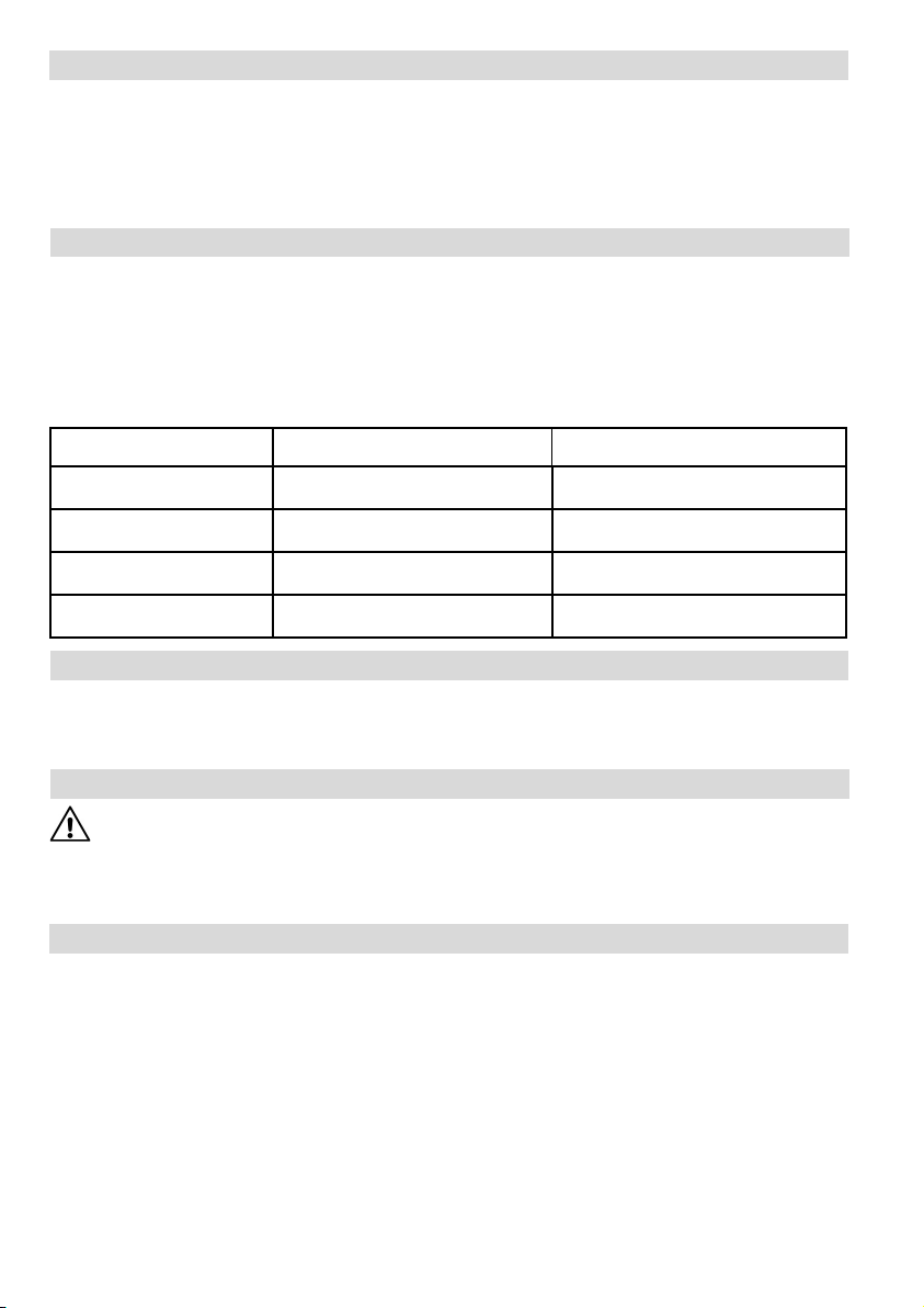
Filterwechsel-Datum Voraussichtlicher Filterwechsel Eingesetzter Filtertyp
Filterwechsel (siehe Bild 4)
Verschließen der Innenblende (Bild 18)
Sommerlüften
Zusatz-/Austauschteile
Reinigung
Page 9
9
About this manual, Safety instructions, Technical data, Disposal 9
Dimension diagrams, Installation position, Range of application 10
Shipping units 10
Assembly: Assembly tube 10
Assembly: Electrical installation and electrical connection 11
Assembly: Fan insert, inside room screen 11
Assembly: Outer screen 11
Closing the inner screen 12
Filter replacement 12
Summer ventilaton, Cleaning, Additional parts and replacement parts 12
Read this manual carefully and completely before assembly. Always observe the general safety
instructions and the safety symbols with information in the text.
Hand out this manual to the user (tenants, proprietors, property management etc.) after comple-
ting assembly.
Symbols in this manual
This symbol warns you against risks of injury
This symbol warns you against risks of injury from electricity
Caution! An y assembly w ork to the ventilation device may only be carried out after disconnecting all poles of the supply voltage. The ventilation device is fitted with protective insulation according to Protection Class II, a protective conductor connection is not required.
Attention! The electric connection may only be made by authorised qualified personnel
and according to the applicable version of VDE 0100.
Attention! This device must not be operated by children and persons (filter replacement/
cleaning) who are not able to operate the device safely due to their physical, sensory or mental
abilities or their inexperience or lack of knowledge. Children should be supervised to ensure
that they do not play with the device.
Supply voltage: 230 VAC 50 Hz
Device voltage: 12 VDC SELV
Protection Class: IP 22
Airflow volume: 5; 10; 15; 20 m³/h in reverse operation, 45 m³/h in exhaust air mode
The packaging must be sorted before disposal. If you wish to dispose of the ventilation device, observe the current regulations. The competent municipal authority will provide information.
Installation Manual English EN
Technical data
Safety instructions
Contents Page:
About this manual
Disposal
Page 10

10
(A) inside; (B) outside
* minimum ** longer lengths possible
The two fans in the ego always operate in opposite directions thus providing supply and exhaust air
simultaneously. Minimum distances to the wall and surrounding components must be observed to
ensure unobstructed air flow without inadmissible mixing of supply and exhaust air!
Picture 2: Minimum di stances to wall and surrounding components
((C) Wall; (D) Window)
Temperature range of application: - 15°C to + 40°C
Can be used at a relative humidity up to 65% in the interior room area (not condensing). The user is
requested to switch off the unit and close the inner screen if the application limits are exceeded.
Ensure supply of fresh air via window ventilation.
Please check your delivery for completeness and mint condition!
Picture 3: Assembly tube
((E) Tube DA 160 mm; (F) Plaster protection cap)
Picture 4: ego- insert
((G) cover; (H) Inner housing sub-part; (I) Filter (2x); (J) Closing element (2x); (K) Heat
exchanger unit with motors; (L) EPP adapter: 2 pieces mounted and optional additional)
Picture 5: Outer screen, type 1/EGA Order-No.: 40019
((M) Cover; (N) Outer screen sub-part)
+ Screw accessories
Picture 6: Weather protection hood, types:
1/HWE-2 white Order-No.: 40107
1/HAZ-2 anthracite Order-No.: 40108
((O) Cover; (P) Frame; (Q) Connectiion screws)
+ Screw accessories
Picture 7: Prepare wall openings for the assembly tubes (e.g. via core drill hole, core bit Ø162
mm). If necessary, shorten the tube to the installation length required.
Make sure there is a slight projection of the tube on both sides to bridge the plaster thick
ness (after plastering, the tube must be flush with the plaster). Insert the tube and seal it
all-round (Assembly adhesive Order No. 38733).
(A) inside; (B) outside; (F) Plaster protection cap)
Picture 8: Apply the inside and outside plaster. ((A) insi de; (B) outside)
Picture 9: Prepare the cable for the device connection in the designated section (e.g. J -Y (ST)
Y4x2x0,8).Cable length approx. 100 to 120 mm. Use the drilling template.
((R) Core drill hole or wall installation tube; (S) Section for device cables)
Shipping units (Pictures 3 to 6)
Dimension diagrams (Picture 1)
Installation position (Picture 2)
Range of application
Assembly: Assembly Tube (Pictures 7 to 9)
Page 11
11
Caution! Any assembly work to the ventilation device may only be carried out after disconnecting all poles of the supply voltage!
Make sure that the supply voltage of all connection lines is voltage-free (dead)! (Separation
from the power supply with a minimum contact opening of 3 mm, e.g. electric fuse separating
all poles).
Each electric circuit of this ventilation system must be fitted with a residual current protection
(e.g.FI switch/RCCB)!
Electric connection only by a specialist!
Additional installations and electrical components in the ventilation unit are not allowed!
Safety instructions
Picture 10: Triggering can be made via variuos LUNOS-controls. The respective installation in
structions apply accordingly. Select the position of the switch. Slit the cable channels.
Connect the cable to the switch and locate the power pack under the switch e.g. 3x
1.5mm², otherwise a smaller cross-section suffices e.g. J-Y(ST)Y 4 x 2 x 0.8) and the
cables to the devices ( e.g. J-Y(ST)Y 4 x 2 x 0.8). Switching and switch are connected in
accordance with the connection plan displayed below.
((T) Device 1 Exhaust/Supply; (U) Other devices (with power pack 5/NT18 (18 Watt):
max. 2 ego, with power pack 5/NT60 (60 Watt): max. 5 e
go)
; (V) Control; (W) Switch)
Picture 11: Drill the fastening bores for the inside room screen using the drilling template and
insert the dowels enclosed.
Note: Observe the label ‚TOP‘, any deviating installation position is not
admissibe for flow-related reasons!
((X) Drilling template; (Y) Device connection cable)
Picture 12: Remove the plaster protection cap. Shorten the EPP adapter to the length of the
assembly tube. In the case of tube lengths above 500 mm, additional adapter pieces
may be mounted!
Insert the fan unit (inner housing sub-part, heat exchanger unit and EPP adapter) into
the assembly tube!
((Y) Device connection cable)
Picture 13: Insert the connection cable (Y) through one of the boots (Z) of the inner housing
sub-part in the section of electrical connection! Fasten the inner housing sub-part to the
wall using the screws enclosed!
Picture 14: Connect the ventilation unit! ((Y) Device connection cable; (Z) Boot)
Picture 15: Mount the cover for the electrical connection (Z19 section and insert the closing
element (J) on top!!
Insert the filter (I) and snap the cover (G) into place!
((H) Inner housing sub-part)
Picture 16: Using the drilling template ((X) - please refer picture 11), drill the fastening drill holes
and insert dowels (in accordance with the surface) provided on-site.
Place the outer screen sub-part (N)on the EPP adapter (N) located in the tube!
Only vertical position of center bar (Z2) is admissible!
Picture 17: Fasten the outer screen sub-part (N) using the screws enclosed!
Place the cover (M) on top!!
Note: The alternative to be assembled weather protection hood has a corresponding installation
manual!
Assembly: Assembly fan insert, inside room screen (Pictures 11 to 15)
Assembly: Outer screen 1/EGA (Pictures 16 and 17)
Assembly: Electrical installation and electrical connection (Picture 10)
Page 12
12
Picture 18: The inner screen can be closed, if required, using the magneti c closing elements
(J) : Place the closing elements with the red side outwards from the inside in front of the
fan grille! Apply the cover (G)!
The filter replacement indicator signalises that a filter is contaminated. For further information pleace read
the instructions of your LUNOS-control.
Remove cover (G), take filter (I) out, insert new or cleaned filter (filters can be cleaned e.g. in a dishwasher),
put cover on.
The ventilation openings must not be blocked or covered.
Please enter the filter changes you have carried out:
Filter replacement date Expected filter replacement Type of filter used
Filter G3 Type 9/FEGO-3R, four-pack Order No.: 39998
Pollenfilter Type 9/FEGO-P, four-pack Order No.: 39982
EPP Adapter Type 2/AD 160 Order No.: 39965
In this function the reversing time of the fan is increased to 1 hour, i.e. the fan runs in supply air mode
for one hour, in the following hour in exhaust air mode etc..
If necessary wipe the indoor screen and covering frame with a dry soft cloth.
Filter replacement and cleaning must not be carried out by children or by persons who are not
able to operate the device safely due to their physical, sensory or mental abilities or their inexperience or lack of knowledge.
LUNOS Germany
LUNOS Lüftungstechnik GmbH & Co. KG Phone +49 30 362 001-0
für Raumluftsysteme Fax +49 30 362 001-89
Wilhelmstr. 31 [email protected]
13593 Berlin ∙ Germany www.lunos.de
E152 02.22
Additional parts and replacement parts
Filter replacement (please refer picture 4)
Closing the inner screen (Picture 18)
Cleaning
Summer ventilation
 Loading...