

Page 1
1
Einbauanleitung / Installation Manual
Universalsteuerung/ Universal Control
Typ: 5/UNI-FT No.: 40089
- Bitte an den Nutzer weiterleiten / Please pass on to user -
manuell, sensorgeführt, via 0-10V
und/oder Funkmodul UNI-EO
Integrierter Zeitnachlauf
Intervallbetrieb programmierbar
Filterwechselanzeige
Technische Daten:
Betriebsspannung: 12 V DC
Funktionsspannungsbereich: 0-10 V
Betriebsschaltstrom: max. 5 A
Anschlussleistung: max. 60 W
Netzteile und max. Geräteanzahl pro Typ.
Es kann immer nur ein Typ pro Steuerung
betrieben werden.
Am 5/NT100 können zwei Steuerungen
mit den oben genannten Geräteanzahlen
parallel betrieben werden.
Manual, sensor-guided or via 0-10V
and/or radio module UNI-EO
Integrated time delay
Interval operation
Filter change indicator
Technical specifications
Operating voltage: 12 V DC
Functional voltage range: 0-10 V
Operational switching current: max. 5 A
Connected load: max. 60 W
Power supplies and device per type. It‘s
only possible to use one type of device
per controller.
On 5/NT100 two controllers can operate
parallel with the device numbers above.
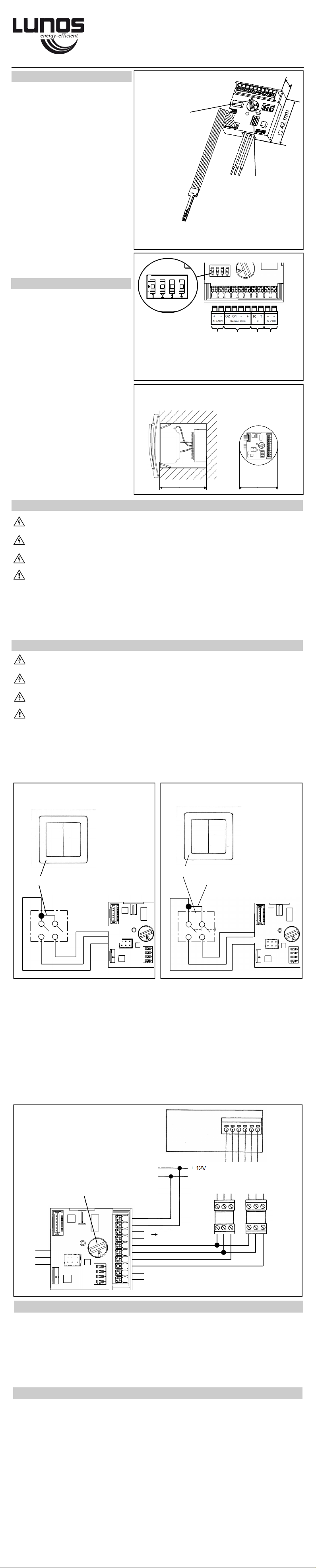
Abmessungen
Dimensions
15,7 mm
Codierschalter
Coding switch
min. 66 mm min. 60 mm
Einbau in Schalterdose / Abzweigdose
Installation in switch box / junction box
Vorsicht! Jede Montagearbeit (Netzanschluss und Einstellung der Miniaturschalter) darf nur bei abgetrennter
Netzspannung erfolgen!
Machen Sie vor Anschluss des Lüftungsgerätes an die Netzspannung alle Anschlussleitungen spannungsfrei!
(Abtrennung vom Netz mit mindestens 3 mm Kontaktöffnung, z.B. elektr. Sicherung).
Jeder zum Lüfter gehörende Stromkreis muss mit einem Fehlerstromschutz (z.B. Fl - Schalter) ausgestattet
sein!
Elektrischer Anschluss nur durch Fachmann!
Zusätzliche Installationen und elektrische Bauelemente im Lüftungsgerät sind unzulässig! Anschlussbilder für weitere Lüfterfunktionen auf Anfrage!
Verwenden Sie folgende Kabel für den elektrischen Anschluss:
Kabel zu den Lüftungsgeräten: z.B. J-Y(St)Y(2x2x0,8), min. 0,5 mm², max. 1,5 mm²
Kabel für die Versorgungsspannung des Netzteils z.B. NYM 3x 1,5 mm²
Taster anschließen und die Taste „▲“ 5 mal innerhalb von 6 Sekunden betätigen. Die rote LED be-
stätigt dies mit 5 mal Blinken.
Steckplatz für Funkmodul
Slot for wireless module
Typ / type UNI-EO 40091
Wechsel von Schalter– auf Tasterbetrieb
Netzteil Serie e² eGO RA15-60
5/NT18 6 3 1
5/NT60 10 5 2
5/NT100 10+10 5+5 2+1
W1 W2
Anschluss eines Tasters
Connection of a push-button
5/W2T
Brücke bauseits
Bridge installation side
▲ ▼
Anschluss eines Schalters
Connection of a switch
I III II
5/W2U
power supply e² series eGO RA15-60
5/NT18 6 3 1
5/NT60 10 5 2
5/NT100 10+10 5+5 2+1
LED (rot/grün)
Feuchte-/Temperatursensor
LED (red/green)
Humidity-/temperature sensor
Funktionen DE
Functions EN
To connect a push-button press the button „▲“ 5 times within 6 seconds. The red LED will flash
5 times for confirmation.
Changeover from switch to push-button operation
Caution! Any assembly work (connection to power supply and setting of the miniature switches) may only be
carried out after disconnecting the supply voltage.
Make sure that the supply voltage of all connection lines is voltage-free (dead). (Separation from the power
supply with a minimum contact opening of 3 mm, e.g. electric fuse).
Each electric circuit of this ventilation system must be fitted with a residual current protection (e.g. FI switch/
RCCB).
Electric connection only by a specialist.
Additional installations and electrical components in the ventilation unit are not allowed.
Connection diagrams for further fan functions upon request.
Use the following cables for the electric connection:
Cable to the ventilation units: e.g. J-Y(St)Y(2x2x0,8), min. 0,5 mm², max. 1,5 mm²
Cable for the supply voltage of the power supply unit e.g. NYM 3 x 1,5 mm²
Elektrischer Anschluss DE
Electrical connection EN
Geräteanschluss
Device connection
Wichtig! Codierschalter entsprechend Tabelle auf S.2 stellen.
Important! Set the coding switch to
the desired functions according to
table on page 2.
+ - S1 + - S2
Anschlussplatine
Junction board
ego
Gerät / Unit
+ - S1 + - S2
e² (1, 3, 5,...)
RA 15-60 (1)
e² (2, 4, 6,...)
RA 15-60 (2)
Wechsel von Taster– auf Schalterbetrieb
Schalter anschließen und Wippe 1 oder 2 für 120 s einschalten, die grüne LED blinkt 5 mal kurz.
Standardmäßig ist an der 5/UNI-FT der Anschluss eines Schalters eingestellt.
By default, the 5/UNI-FT is set to the connection of a switch.
Changeover from push-button to switch operation
To connect a switch and turn on the switch rocker 1 or 2 for 120 seconds. The green LED will
flash 5 times for confirmation.
Ansicht von vorn
Front view
W1 W2
grau / grey
rot / red
schwarz / black
grau / grey
rot / red
schwarz / black
a b c
d
a. 0-10V analoger Eingang / analogue Input
b. Geräteanschluss / device connection
c. digitaler Ein-/Ausgang / digital in-/output
d. 12V DC Spannungsversorung / power supply
-
+
0-10 V Eingang / Input - TAC, 5/GS (optional)
T
R
5/GS (optional)
R
T
Externe regelbarer DC Spannungsquelle DE
Stufe / Stage 0: 0,6 V - 0,9 V AUS / OFF
Stufe / Stage 1: 1,1 V - 1,4 V 6,1 V - 6,4 V
Stufe / Stage 2: 1,6 V - 1,9 V 6,6 V - 6,9 V
Stufe / Stage 3: 2,1 V - 2,4 V 7,1 V - 7,4 V
Stufe / Stage 4: 2,6 V - 2,9 V 7,6 V - 7,9 V
Stufe / Stage 5: 3,1 V - 3,4 V 8,1 V - 8,4 V
Stufe / Stage 6: 3,6 V - 3,9 V 8,6 V - 8,9 V
Stufe / Stage 7: 4,1 V - 4,4 V 9,1 V - 9,4 V
Stufe / Stage 8: 4,6 V - 4,9 V 9,6 V - 9,9 V
The universal control can be connected to an external controllable low-voltage source via the 0-10V
input shown above and thus be integrated into a home automation system, for example. The following voltages are assigned to the corresponding ventilation levels.
In addition to normal operation with heat recovery (0.6 V - 5 V) (i.e. both fans run balanced with the
same volume flow), the control can also be switched to an alternative ventilation operation. This is
used for summer ventilation or pure ventilation (6.1 V - 10 V). Despite the lack of a bypass, cool fresh
air can be transported into the living unit in summer.
At a voltage of 0 V - 0.4 V, the controller works independently, according to internal sensors.
Über den oben gezeigten 0-10V Eingang kann die Universalsteuerung an eine externe regelbare
Niederspannungsquelle angeschlossen werden und so z.B. in ein System zur Hausautomatisierung
eingebunden werden. Folgende Spannung sind den entsprechenden Lüftungsstufen zugeordnet.
Neben dem normalen Betrieb mit Wärmerückgewinnung (0,6 V - 5 V) (d.h. beide Ventilatoren laufen
balanciert bei gleichem Volumenstrom) kann die Steuerung auch in einen alternativen Lüftungsbetrieb versetzt werden. Dieser dient zum Sommerlüften oder reinem Ablüften (6,1 V - 10 V). So kann
trotz fehlendem Bypass im Sommer kühle frische Luft in die Wohneinheit befördert werden.
Bei einer Spannung von 0 V - 0,4 V arbeitet die Steuerung eigenständig, nach interner Sensorik.
External adjustable DC voltage source EN
Page 2
2
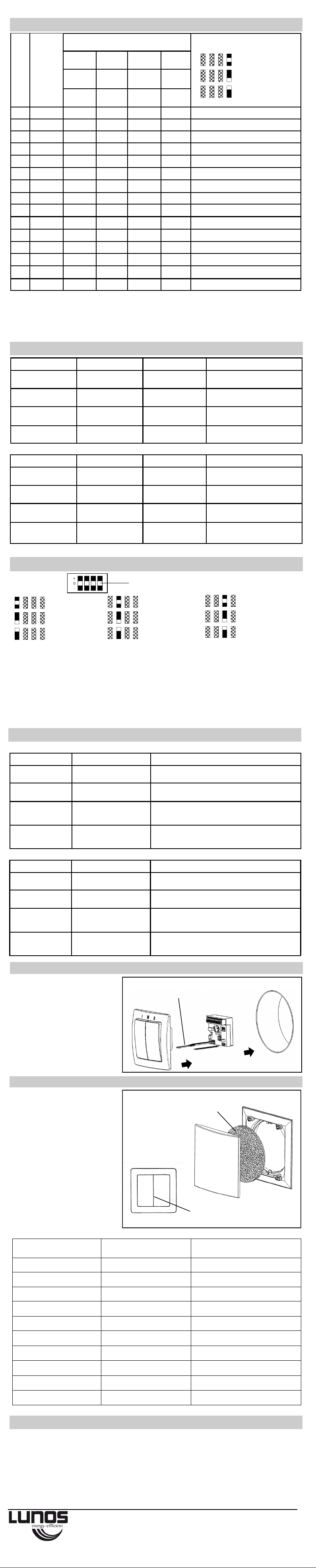
Codierschaltereinstellungen / Coding switch positions DE / EN
Lüftertyp
Fan type
Stufe 0
Level 0
Stufe I
Level I
Stufe II
Level II
Stufe III
Level III
W1
AUS / OFF
W1
EIN / ON
W1
AUS / OFF
W1
EIN / ON
Wippe 2
AUS / OFF
Wippe 2
AUS
Wippe 2
EIN
Wippe 2
EIN
0 RA 15-60
AUS / OFF 15 m³/h 30 m³/h 45 m³/h
1 RA 15-60 AUS / OFF 15 m³/h 30 m³/h 60 m³/h
2 RA 15-60 15 m³/h 30 m³/h 45 m³/h 60 m³/h
3 e² AUS / OFF 15 m³/h 30 m³/h 38 m³/h e²kurz / e²short
4 e² 15 m³/h 20 m³/h 30 m³/h 38 m³/h e²kurz / e²short
5 e²60 AUS / OFF 15 m³/h 30 m³/h 40 m³/h e²60kurz / e²60short
6 e²60 5 m³/h 15 m³/h 30 m³/h 40 m³/h e²60kurz / e²60short
7 e²60 AUS / OFF 15 m³/h 30 m³/h 60 m³/h e²60kurz / e²60short
8 e²60 15 m³/h 30 m³/h 45 m³/h 60 m³/h e²60kurz / e²60short
9 ego AUS / OFF 5 m³/h 10 m³/h 45 m³/h* Stufe III WRG / level III HRV 20m³/h
A ego 5 m³/h 10 m³/h 20 m³/h 45 m³/h* Stufe III WRG / level III HRV 20m³/h
B ego 10 m³/h 20 m³/h 45 m³/h* 45 m³/h* Stufe III WRG / level III HRV 20m³/h
C e²60** AUS / OFF 15 m³/h 30 m³/h 60 m³/h e²60kurz / e²60short
D e²60** 15 m³/h 30 m³/h 45 m³/h 60 m³/h e²60kurz / e²60short
E 0-10 V
Programme und Luftvolumenströme
Programs and airflow levels
Deutschland / Germany
LUNOS Lüftungstechnik GmbH & Co. KG Phone: +49 30 36 20 01 - 0
für Raumluftsysteme Fax: +49 30 36 20 01 - 89
Wilhelmstr. 31 [email protected]
13593 Berlin www.lunos.de
Codierschalterstellung Coding switch position
Montage von Sensor und LED / Installation of the sensor and LED DE / EN
LED + Feuchte-/Temperatursensor
LED + humidity-/temperature sensor
Filterwechsel / Filter change indicator DE / EN
Achtung! Die LED und der Feuch-
te-Temperatursensor werden in die
kreisrunde Öffnung auf der Unterseite des Schalters eingeschoben!
Die Montage zusammen mit einem
Taster erfolgt auf gleiche Weise.
Attention! The LED and the humidity-temperature sensor are inserted in
the circular opening on the bottom
side of the switch.
The assembly together with a pushbutton is carried out in the same
way.
Zusatz-/Austauschteile / Additional and Replacement parts DE / EN
Funkmodul UNI-EO Best.-Nr. / order.-no.: 40091
Schalter 5/W2U Best.-Nr. / order.-no.: 39972
Taster 5/W2T Best.-Nr. / order.-no.: 40011
Netzteil 5/NT18 Best.-Nr. / order.-no.: 39973
Netzteil 5/NT60 Best.-Nr. / order.-no.: 39974
Netzteil 5/NT100 Best.-Nr. / order.-no.: 40096
E206 05.22
Filter
filter
Ein verschmutzter Filter wird durch
dauerhaftes rotes Leuchten der LED
unterhalb des Schalters signalisiert.
Deckel abnehmen, Filter entnehmen, neue oder gereinigte Filter
einlegen (die Reinigung des Filters
kann z.B. im Geschirrspüler erfolgen), Deckel aufsetzen.
Rücksetzen der Filterwechselanzeige siehe Punkt „Bedienung“.
A permanent red light of the LED
beneath the switch signals that the
filter is contaminated.
Remove front cover, take filter out,
insert new or cleaned filter (filters
can be cleaned e.g. in a
dishwasher), put lid on.
Reset the filter change indicator as
discribed under point „Handling“.
I III II
LED leuchtet unter Schalter
LED lights up under the switch
Intervall AUS
Interval OFF
alle 4 Std. 30 min *
every 4h 30 min *
alle 2 Std. 15 min *
every 2h 15 min *
Weißer DIP-Schalter
White DIP-Switch
Werkseinstellung
Factory settings
Feuchteregelung*** AUS
Humidity control*** OFF
EIN 50% r.F. - 70% r.F
ON 50% r.h. - 70% r.h.
EIN 45% r.F. - 75% r.F
ON 45% r.h. - 75% r.h.
DIP-Schalter Einstellung / DIP-Switch settings DE / EN
1 2 3 4
* Period of summer ventilation 8h maximum, then back to normal operation.
* Der Intervallbetrieb wird je Gerät in der Stufe II der oben aufgeführten Tabelle ausgeführt.
** Nachlaufzeit bedeutet, dass der Lüfter nach Herunterschalten von Stufe 3 nachläuft.
*** Die Feuchteregelung ist aktiv, wenn Stufe 0 des Serienschalters eingestellt ist, also auch, wenn dadurch der
Lüfter AUS ist. Ein komplettes Deaktivieren ist nur über die DIP-Schalter möglich! Das Zurückschalten des Lüfters
durch Schalter oder Taster in die Feuchteregelung wird durch zweimaliges grünes Blinken der LED quittiert. Wenn
die Feuchteregelung aktiv ist, blinkt die LED alle 15s grün.
* The interval operation is carried out for each device in level II of the table above.
** Delay time means that the fan will continue to run after switching down from level 3.
*** The humidity control is active when the level 0 is set, i.e. also if the fan is OFF. Complete deactivation is only
possible via the DIP-switches. Switching back the fan by switch or push button into the humidity control is confirmed
by the LED flashing green twice. When humidity control is active, the LED flashes a green light every 15 seconds.
Funktion Schalter Taster Rückmeldung LED
Änderung
Volumenstrom
- „▲“ oder „▼“ betätigen 2s nach letzter Betätigung der Stufe
entsprechendes rotes Blinken
Zurücksetzen
Filterwechselanzeige
Einmaliges Wippen von
W1 innerhalb 3s
5s W1 gedrückt halten 3 maliges rotes Blinken
Sommerlüften
aktivieren*
Einmaliges Wippen von
W2 innerhalb 3s
5s W2 gedrückt halten LED leuchtet 1x lang (3s) grün
Sommerlüften
deaktivieren
Einmaliges Wippen von
W2 innerhalb 3s
5s W2 gedrückt halten LED leuchtet 2x kurz (je 1s) grün
Functions Switch Push-button Feedback LED
Change flow rate - Press „▲“ or „▼“ Lights up red 2s after last switching
according selected level
Reset filter change
indicator
Rocker W1 one time
within 3s
Press W1 for 5s Lights up red 3 times
Activate summer
ventilation*
Rocker W2 one time
within 3s
Press W2 for 5s Lights up green 1 time long (3s)
Deactivate summer
ventilation
Rocker W2 one time
within 3s
Press W2 for 5s Lights up green 2 times short (every
1s)
Bedienung / Handling DE / EN
* Dauer des Sommerlüftens max. 8h, dann wieder Normalbetrieb.
* Abluft ohne Wärmerückgewinnung / exhaust air without heat revovery
** Unpaariger betrieb mit einm Gerät an S1 und zwei Geräten an S2 /
** Unpaired operation with 1 unit conneted to S1 and two units connected to S2
Bitte mit der maßgebenden Tabelle auf der Rückseite der vorliegenden Steuerung vergleichen./
Please compare with the relevant table on the back of the delivered controller.
Ein Anleitung zur Kalibrierung der Volumenströme ist auf Anfrage erhältlich.
Flow rate calibration instructions are available upon request.
Funktion Voraussetzung Rückmeldung LED
Werksreset Codierschalter auf F
DIP-Schalter auf „0000“
5x Blinken
Intelligenz der
Feuchteregelung
Codierschalter auf F
DIP-Schalter „000+“
1x Blinken aktiviert
2x Blinken deaktiviert
LED Funktion Codierschalter 0-E
1x Blinken Vollfunktion
2x Blinken vollständig deaktiviert
3x Blinken Filterwarnung deaktiviert
Lüftungsbetrieb Codierschalter auf F
DIP-Schalter auf „00+0“
1x Blinken Balanciert
2x Blinken dynamische Disbalance (DIBt)
3x Blinken erweiterte dynamische Disbalance
Programmiermodus / Programming mode DE / EN
Function Requirements Feedback LED
Factory reset Coding switch on F
DIP-switch „0000“
5x flashing
Intelligence of the
Humidity control
Coding switch on F
DIP-switch „000+“
1x flashing activated
2x flashing deactivated
Function of LED Coding switch on 0-E
1x flashing full function
2x flashing completely deactivated
3x flashing filter warning deactivated
Ventilation mode Coding switch on F
DIP-switch „00+0“
1x flashing balanced
2x flashing dynamic disbalance (DIBt)
3x flashing extended dynamic disbalance
Steuerung entsprechend Tabelle und Funktion einstellen und W1 oder W2 10x Wippen oder bei Taster 30s drücken.
Set the control according to the table and function and rocker W1 or W2 10x or press the push-button 30s.
1 2 3 4
Sonderfunktion
Special feature
deaktiviert
deactivated
aktiviert
activated
-
Nachlaufzeit AUS
Time delay OFF
Nachlaufzeit 15 min **
Time delay 15 min **
Nachlaufzeit 30 min **
Time delay 30 min **
1 2 3 4
1 2 3 4
FIlterwechsel /
Filter change date
gewaschen oder ersetzt /
washed or replaced
Filtertyp /
Filter type
 Loading...