

Page 1
Version 003
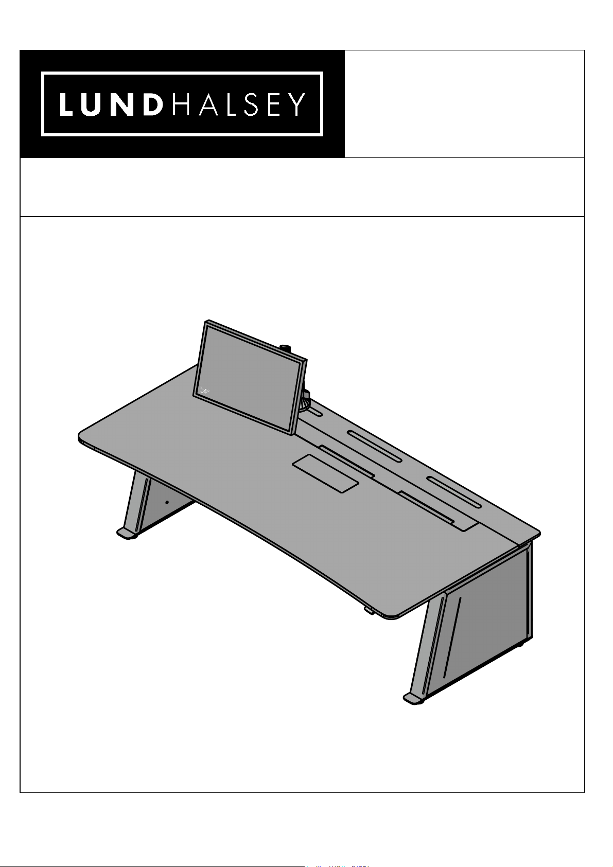
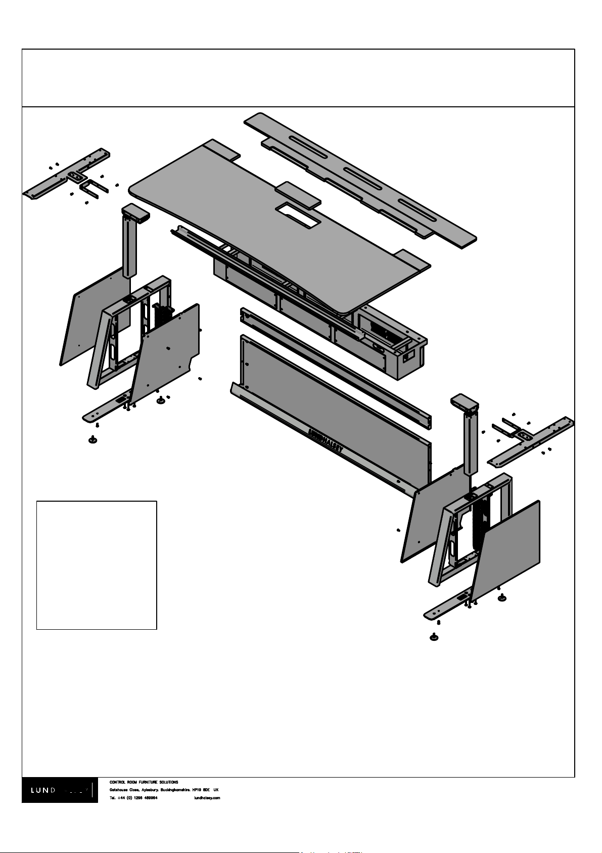
VISIONLINE. Assembly instructions
Page 2
®
Version 003
VISIONLINE. Assembly instructions
1.
Warning! Heavy items require at least 2 people to lift.
O:\Quality & Environmental\ISO 9001\New product Folder\Visionline\Bills drawing Development folder\Current drawings\Bill Current drawing\Visionline\Assembly Instructions\stock-vector-warning-heavy-object-402273037.jpg
To prevent scratches where necessary place parts onto a
soft, clean surface and do not slide parts
Page 3
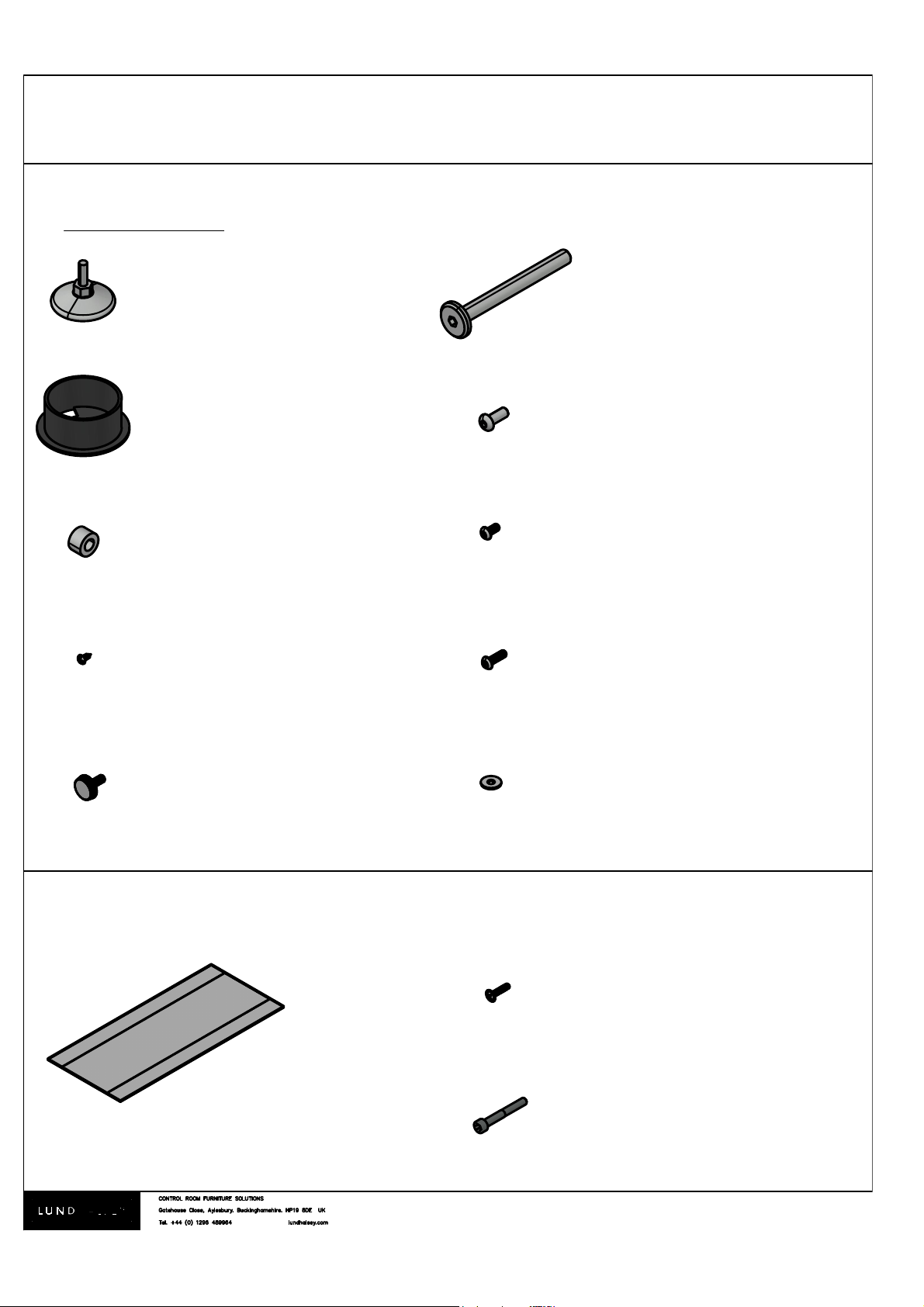
Adjustable feet x4
Cable caps x2
15mm M8 Nylon washers x2
4x10mm screws x 8
M4 23mm Flange head fixing
x 2
60mm Flat allen head fixing x8
Cable putty x1 (used on HA
desks only)
25mm M8 button head fixing x 6
10mm M6 button head fixings x 97
M6 washers x 21M6 Thumbscrew x 2
®
Version 003
VISIONLINE. Assembly instructions
Fixing kit
2.
Fixings for height adjustable desks.
40mm M6 allen head fixing x 2
20mm M6 pozi drive fixings x 4
Fixing kit supplied for largest style desk. There may be some fixings left over.
Page 4
®
Version 003
VISIONLINE. Assembly instructions
1 2
3 4
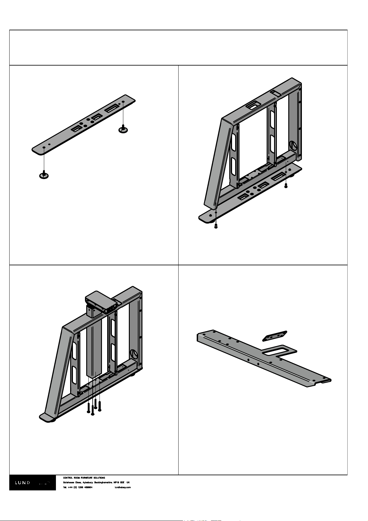
Fit adjustable feet to foot plate
Fit foot plate to leg frame with 25mm M8
button head fixings.
Fit Actuator through top of leg assembly
and fix using 60mm flat Allen head fixing.
Remove bracket from T plate (see stage 12)
3.
Page 5
®
Version 003
VISIONLINE. Assembly instructions
7 8
5 6
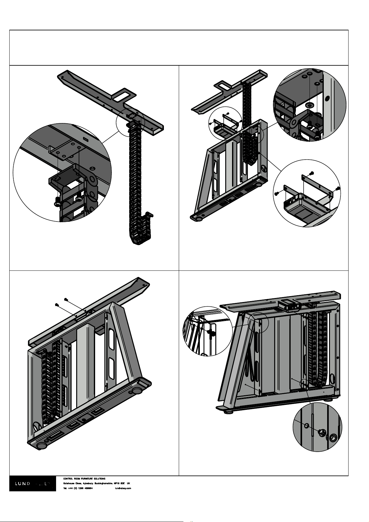
Fit energy chain to T plate using 10mm
M6 button head fixings.
1. Feed energy chain into leg assembly and
fix using 10mm M6 button head fixings and
m6 washers
2. Fit bracket to actuator using 10mm M6
button head fixings.
Fit T plate to bracket fitted to actuator
using 10mm M6 button head fixings.
4.
P
DETAIL P
SCALE 1.2000
A
1.
B
DETAIL B
SCALE 1:2
2.
Fix outer panel to leg assembly with 4x10mm x4.
I
M
To prevent scratches place gloss panel onto a soft,
clean surface and do not slide parts
Page 6
®
Version 003
VISIONLINE. Assembly instructions
9
11
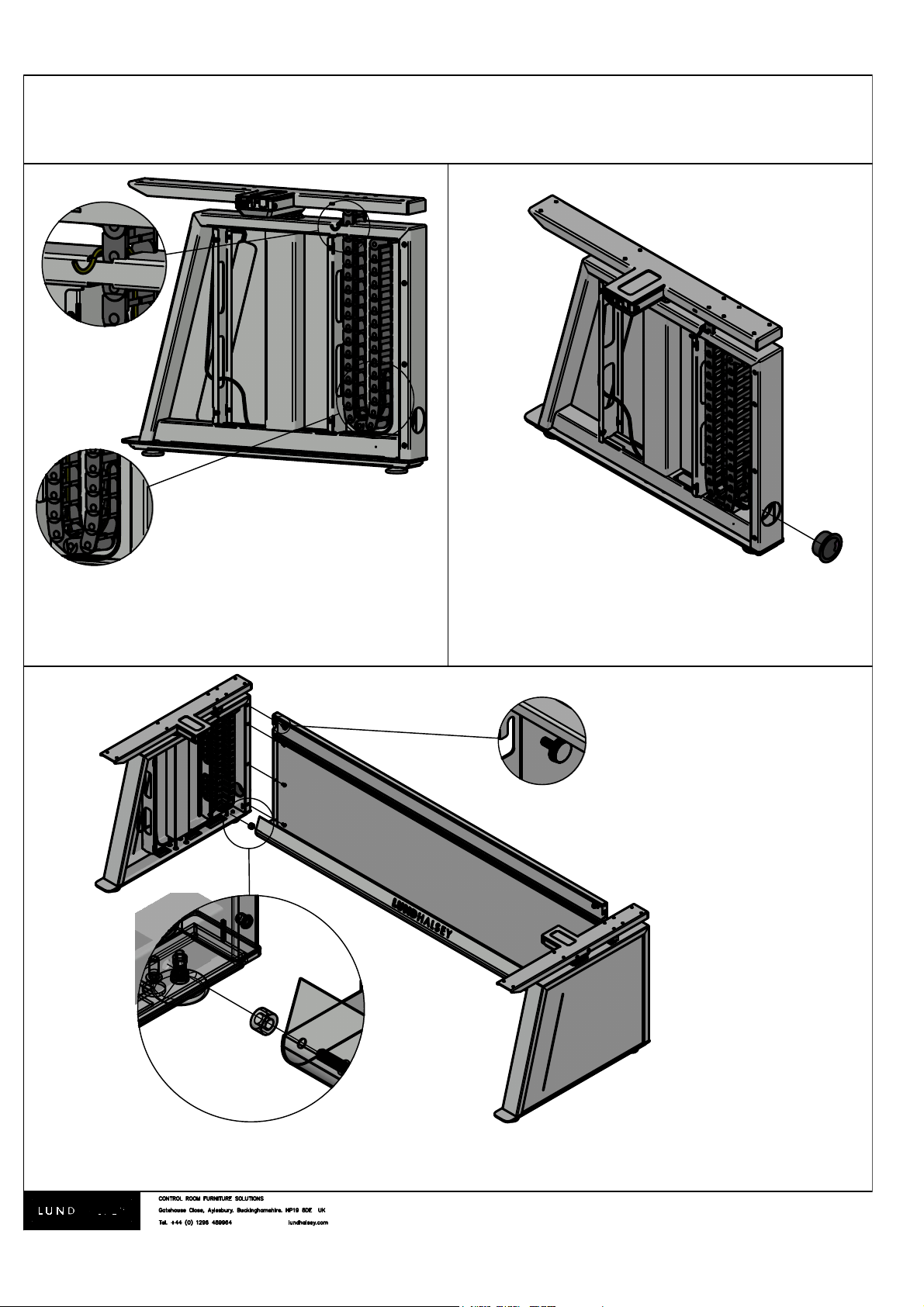
Fit cable cap to rear of leg assembly.
Repeat steps 1 to 9 for opposite leg assembly.
Attach both leg assemblies to large modesty panel with 25mm M8 button head fixings with 15mm M8
spacer and 10mm M6 button head fixings. Attach small (top) modesty panel to leg assemblies using M6
thumbscrews (do not over tighten).
5.
10
Q
Feed cables all the way through leg frame, into
the energy chain and out the top of the leg. see
page 12 for further cable routing examples.
R
DETAIL R
SCALE 1:2
C
D
If Bridging cabinets are
being used please refer
to Bridging cabinet
assembly instructions
Page 7
®
Version 003
VISIONLINE. Assembly instructions
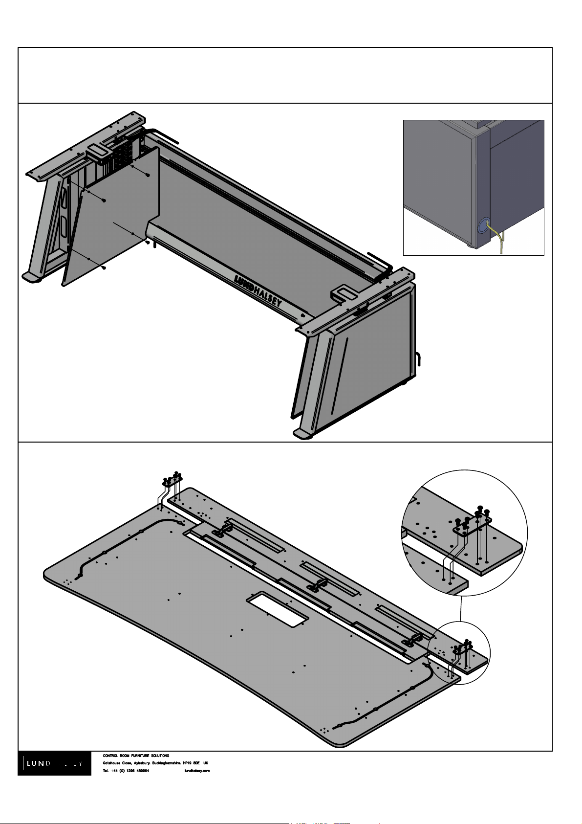
13.
Attach rear shelf assembly to work surface with
metal bracket (see stage 4) and 10mm M6
button head fixings.
E
6.
To prevent scratches place work surface onto a
soft, clean surface and do not slide parts
Feed any power cables required into leg
assembly and through energy chain. Fit inner
black steel panel to leg assembly with 10mm
M6 button head fixings.
12.
Page 8
®
Version 003
VISIONLINE. Assembly instructions
7.
15.
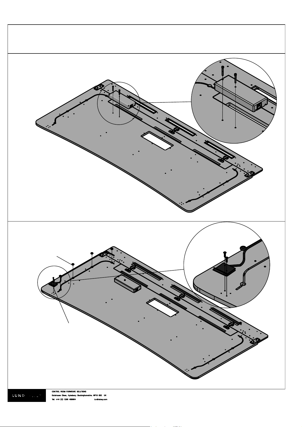
Fit controller unit to underside of work surface
using M4 23mm flange head fixings. Secure
cables into place using the cable putty.
Height adjustable desks only.
Fixed height desks skip to step 16 on page 8.
Cable putty.
###### #
SCALE
######
Controller unit can be fitted on either
left or right hand side of work surface.
N
DETAIL N
SCALE 0.6500
Fit actuator power control box to underside of
work surface using 2x M6 40mm Allen
head fixings.
O
DETAIL O
SCALE 1:2
14.
Page 9
®
Version 003
VISIONLINE. Assembly instructions
16
17
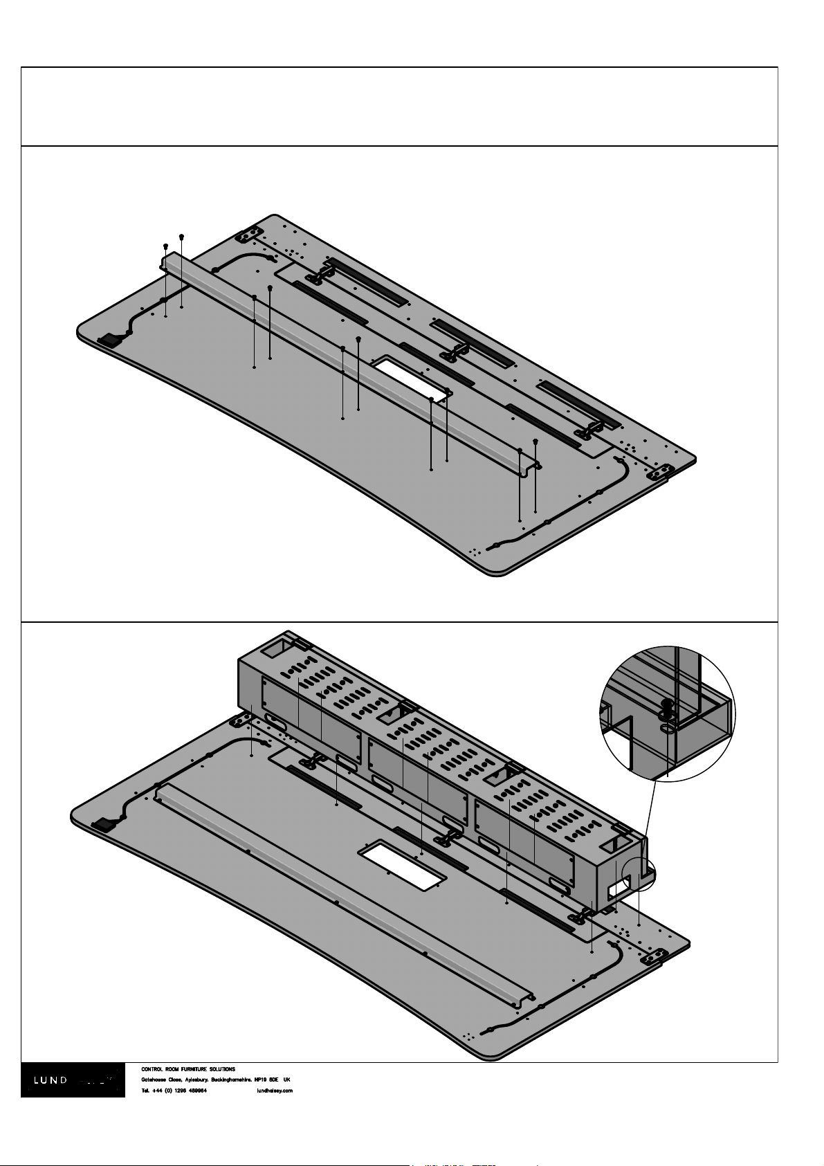
Attach support front rail to underside of work
surface using 10mm M6 button head fixings.
F
DETAIL F
SCALE 1:1
Attach cable tray box to underside of work
surface and rear shelf assembly using 10mm
M6 button head fixings and M6 washers.
8.
Page 10
®
Version 003
VISIONLINE. Assembly instructions
18.
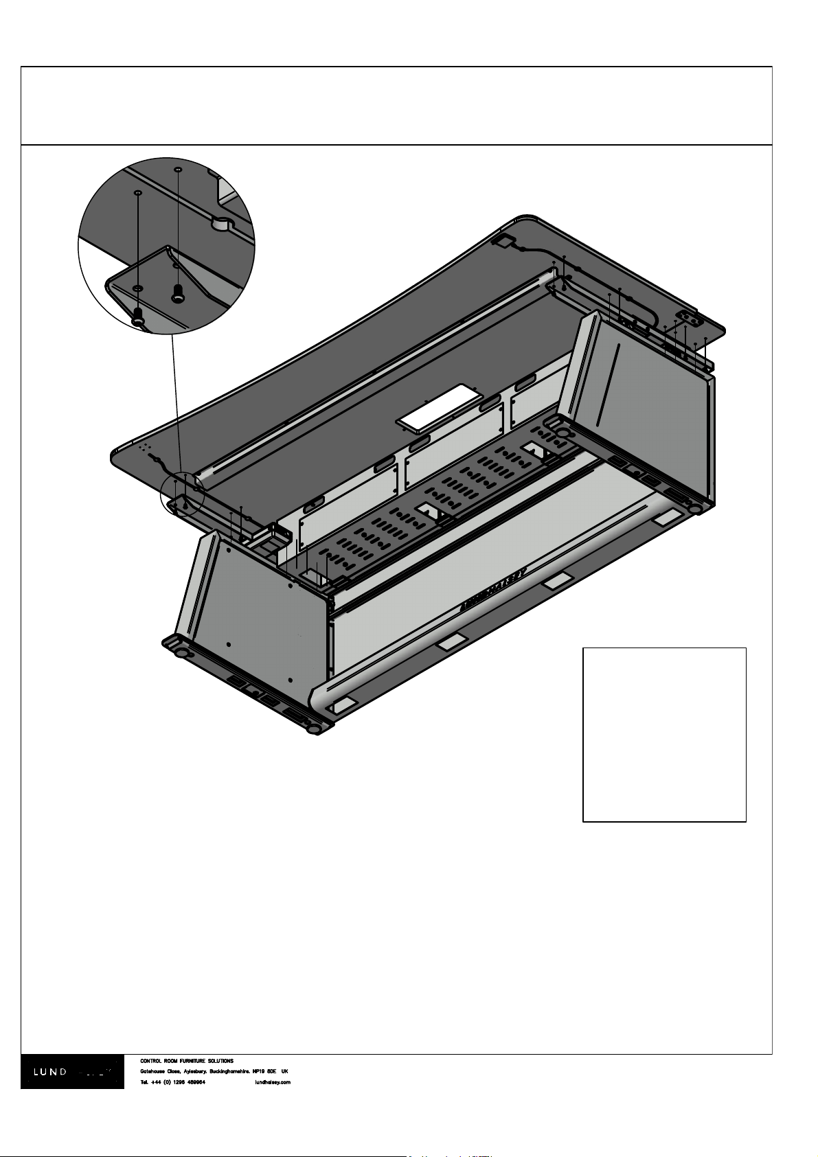
Turn work surface and cable tray box assembly over and fit to leg and modesty assembly using
10mm M6 button head fixings.
Warning! Heavy items require at least 2 people to lift.
9.
O:\Quality & Environmental\ISO 9001\New product Folder\Visionline\Bills drawing Development folder\Current drawings\Bill Current drawing\Visionline\Assembly Instructions\stock-vector-warning-heavy-object-402273037.jpg
H
DETAIL H
SCALE 1:1
Page 11
®
Version 003
VISIONLINE. Assembly instructions
19a
10.
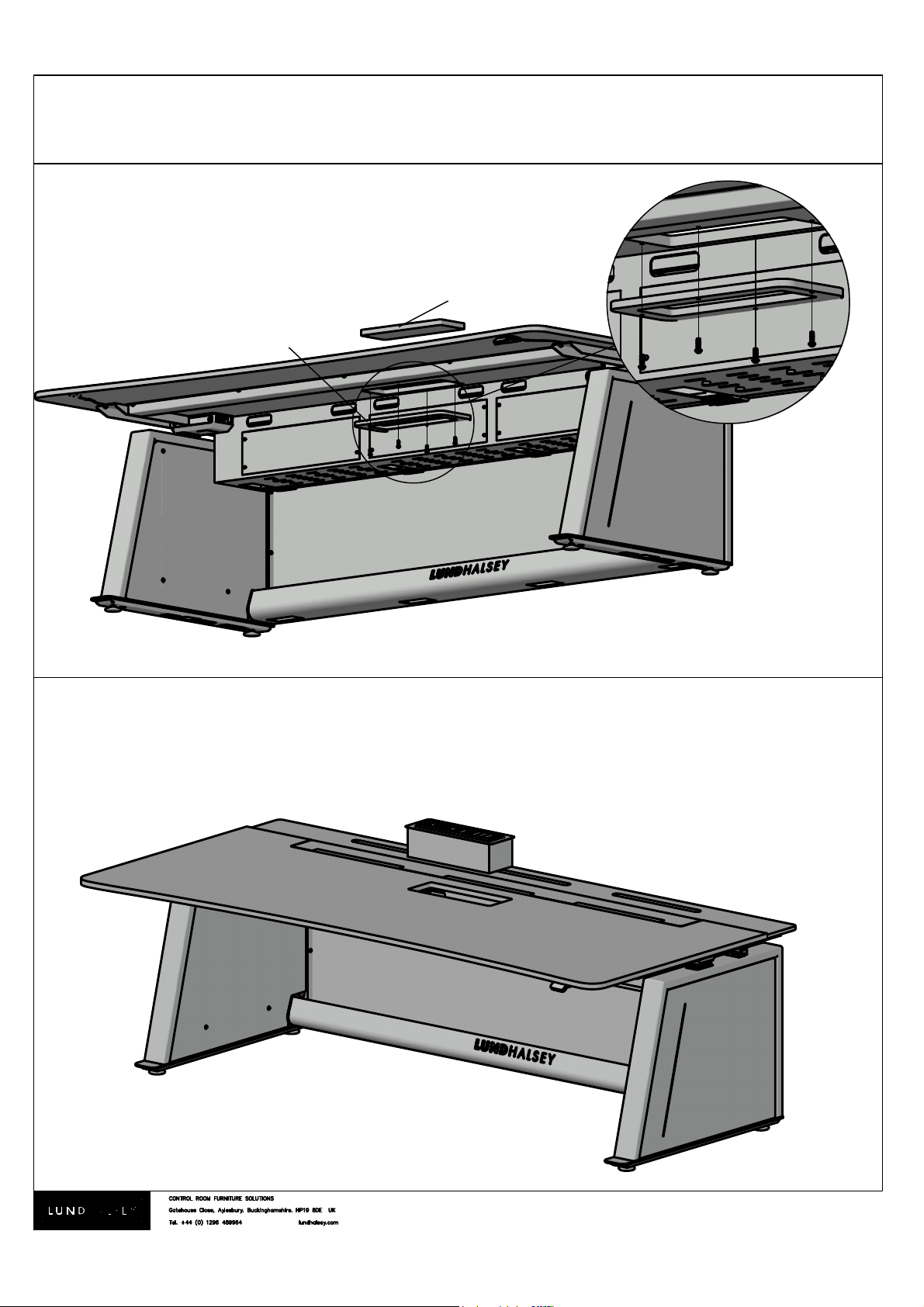
Remove infill panel and support ring if
previously fitted and drop Kontrol Touch power
dock into place.
Desks without Kontrol Touch power dock.
Fit infill support ring to underside of worktop
with M4 x 20mm fixing and drop infill panel into
place.
Infill panel
Infill support ring
Desks with Kontrol Touch power dock.
19b
G
DETAIL G
SCALE 1:2
Page 12
®
Version 003
VISIONLINE. Assembly instructions
11.
J
DETAIL J
SCALE 0.4000
K
DETAIL K
SCALE 0.4000
L
DETAIL L
SCALE 0.4000
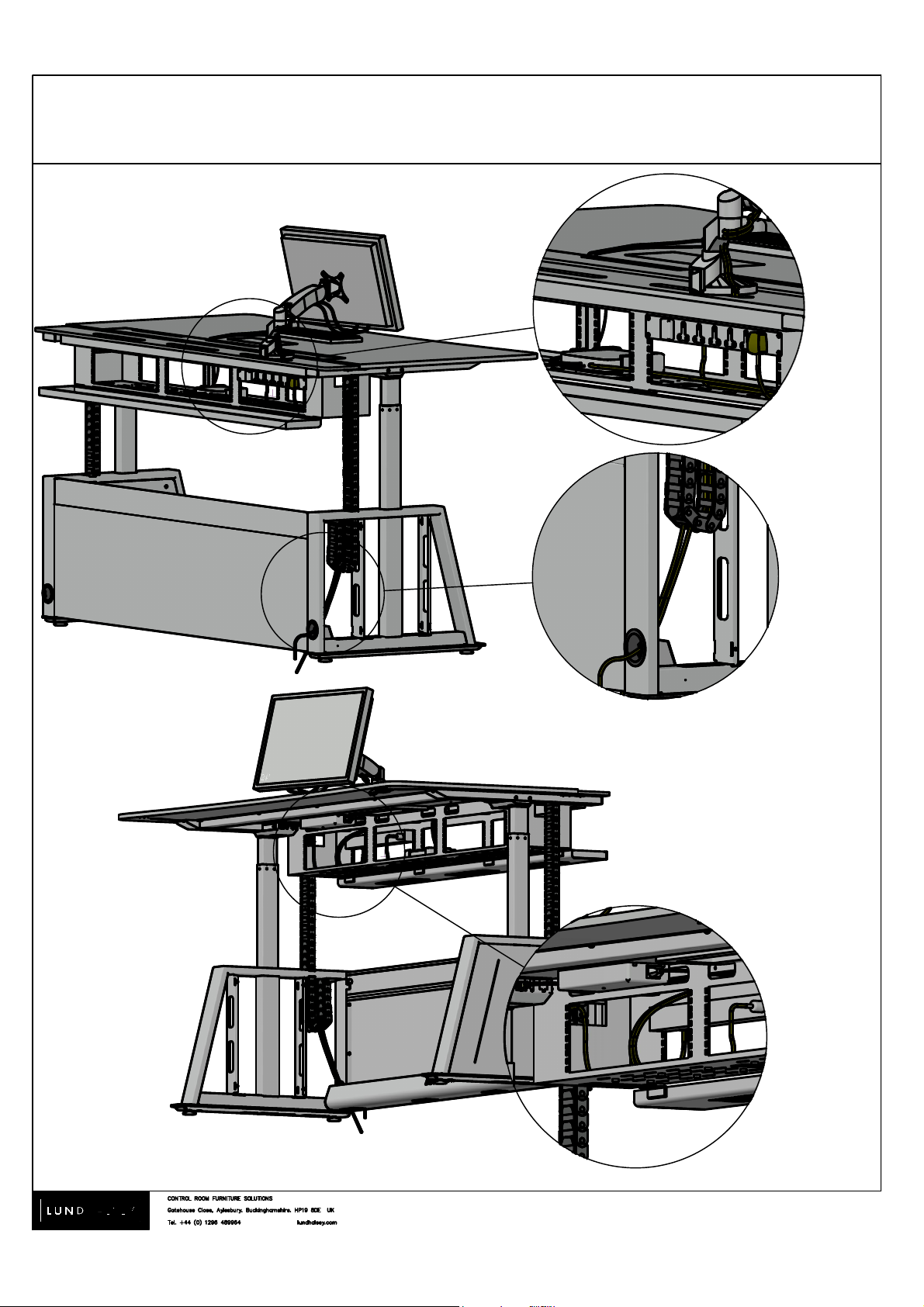
Note: Some components removed for clarity.
Example cable routing
Page 13

®
Version 003
VISIONLINE. Assembly instructions
12.
Example cable routing
On fixed height desks and height adjustable desks in the lower position access to cable tray box
rear door can be achieved by loosening thumbscrews and removing small modesty panel.
S
T
 Loading...