

Page 1

Installation Guide
Lumisys MX Series
1025 Cobb Place Blvd Suite 100 Kennesaw, GA 30144 • 800-241-9173 • www.anybas.com
Page 2
ATTENTION
!
!
!
Installation Guide
Mx Series
Lighting Relay Panel
This section serves as a notice of the immediate or potential dangers involved when working with
the equipment described throughout this manual. Any person involved in installation, maintenance,
or service of the equipment should first carefully examine the equipment and read the instructions
contained in this manual to ensure that personal and/or equipment injury is avoided.
The following safety messages are used throughout this manual to alert of immediate or potential
danger to life or property:
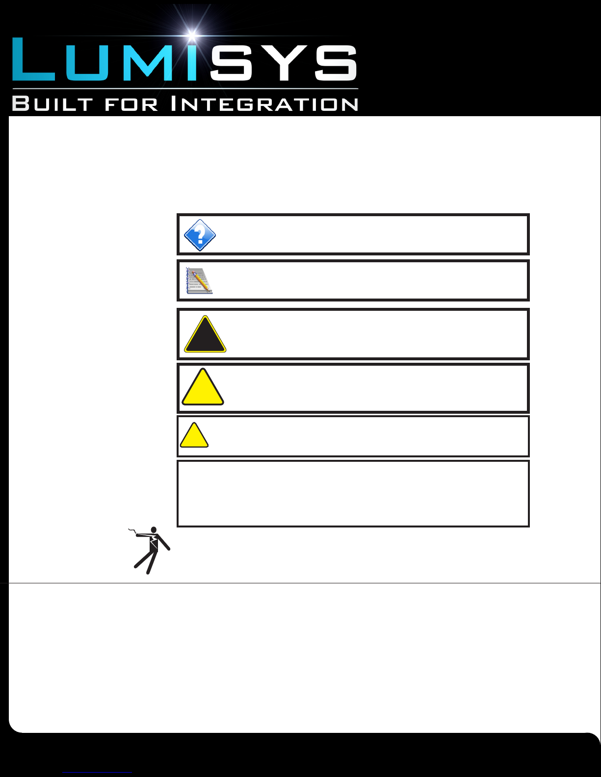
Hint Indicates a tip or trick to help you.
Note Indicates an important note.
DANGER! Indicates an immediately hazardous situation which,
if not avoided, will result in death or serious injury.
Disclaimer
WARNING! Indicates a potentially hazardous situation which, if
not avoided, can result in death or serious injury.
CAUTION: Indicates a potentially hazardous situation which, if not
avoided, can result in minor or moderate injury.
CAUTION: Used without the safety alert symbol, indicates a potentially hazardous situation which, if not avoided, can result in personal or
property damage. Failure to comply with proper handling of the Lumisys
products may void your warranty
In addition, this symbol may appear in the margin of specific portions of text as a safety reminder.
Applicable instruction steps will be listed beneath the symbol.
This equipment has been tested and found to comply with the limits for a Class A digital device,
pursuant to part 15 of the FCC Rules. These limits are designated to provide reasonable
protection against harmful interference when the equipment is operated in a commercial
environment. This equipment generates, uses, and can radiate radio frequency energy and, if
not installed and used in accordance with the instruction manual, may cause harmful interference
to radio communications. Operation of this equipment in a residential area is likely to cause
harmful interference, in which case the user will be required to correct the interference at his own
expense.
Instructions contained in this user’s guide should be performed only by qualified persons in
accordance with local and national codes. Lumisys® Lighting and its affiliates assume no
responsibility for any consequences related to the improper use of this manual.
0726070122
Due to continuous product improvement, Lumisys reserves the right to change product specications without notice.
www.anybas.com
Lumisys is a Registered Trademark
Page 2
Page 3

Table of Contents
Installation Guide
Mx Series
Lighting Relay Panel
Overview ..............................................................................................................
Inspection ............................................................................................................
Installation ............................................................................................................
Connecting the Power Supply .............................................................................
Connecting the Power Supply con’t .....................................................................
Connecting Branch Circuit Wires .........................................................................
Connecting Branch Circuit Wires con’t ................................................................
Connecting Switch Inputs ....................................................................................
Connecting Switch Inputs con’t ............................................................................
Connecting the RS-485 Network .........................................................................
Connecting Lumisys LS5 Photocell Inputs ...........................................................
Adding and Removing LTR Relays ......................................................................
Connecting to Digi-Touch Addressable Switch Network ......................................
Terms and Conditions of Sale ..............................................................................
3
4
5
6
7
8
9
10
11
12
13
14
15
16
0726070122
Due to continuous product improvement, Lumisys reserves the right to change product specications without notice.
www.anybas.com
Lumisys is a Registered Trademark
Page 3
Page 4
Installation Guide
Mx Series
Lighting Relay Panel
Overview
This document provides instructions on how to physically install the Lumisys MX Series Lighting Relay Panel. For panel
conguration and programming refer to Maxiom User’s Guide- Hardware and Maxiom User’s Guide - Software. For network
point descriptions and integrations to a building automation system refer to the appropriate Maxiom Integration Guide.
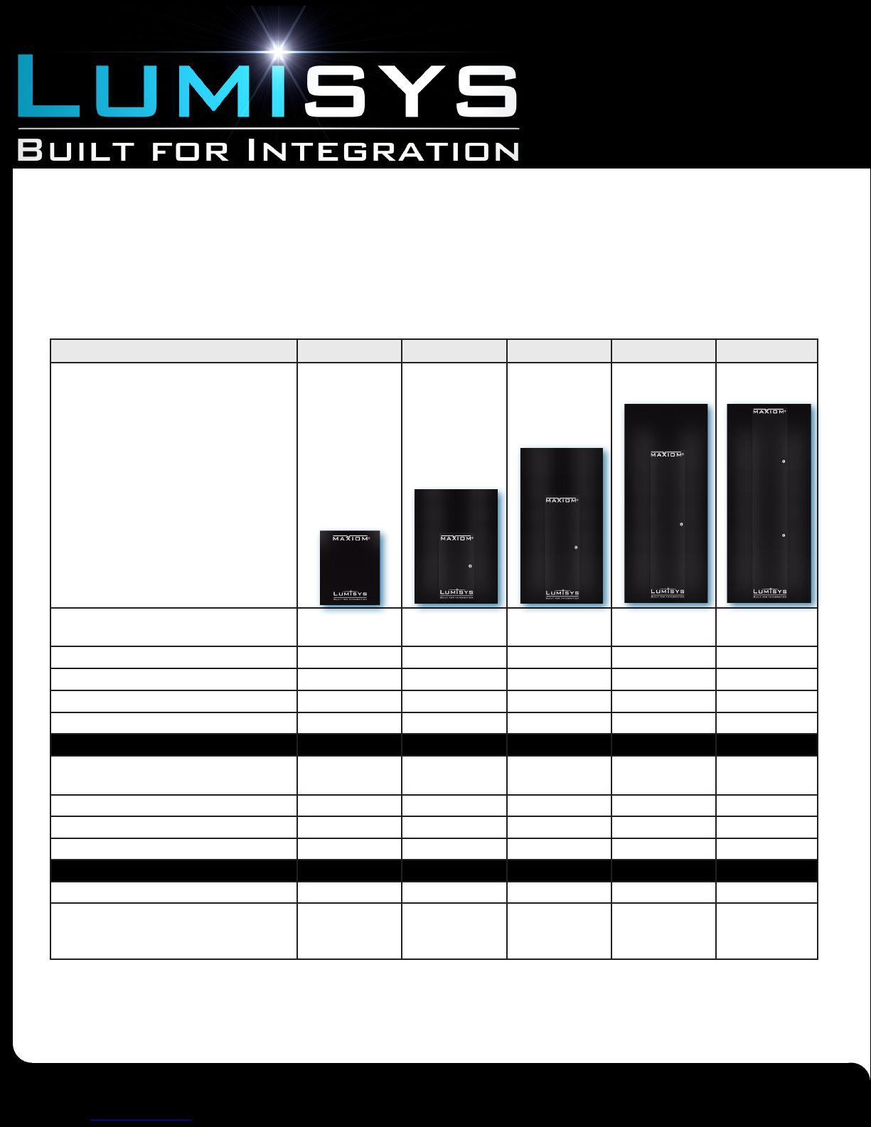
Product Family Comparison
MX08 MX16 MX32 MX48 MX60
Panel
Dimensions (Width x Height x Depth) 13” x 16” x 4” 18” x 25” x 5 3/4” 18” x 33 3/4” x
5 3/4”
Contactor Mounting Space N/A 8.0” x 8.0” x 5.0” 8.0” x 8.0” x 5.0” 8.0” x 8.0” x 5.0” N/A
Trim Style Screw on Tru-lock Tru-lock Tru-lock Tru-lock
Controller Lx5 Lx5 Lx5 Lx5 Lx5
Flash Upgrade Yes Yes Yes Yes Yes
Inputs
Digital Subnet for Switches and Occupancy
Sensors
Binary inputs available without option card 24 24 56 88 120
Analog Inputs available without option card 6 6 6 6 6
Optional Telephone Override Card No Yes Yes Yes Yes
Outputs
Relay Panel Capacity 8 16 32 48 60
Latching Relay with manual override on relay Yes,
Warranty 24 months from date of shipment.
Refer to Lumisys Terms and Conditions of Sale for additional details.
Digi-Touch Native Digi-Touch Native Digi-Touch Native Digi-Touch Native Digi-Touch Na-
Lumisys True
Relay (LTR)
Yes,
Lumisys True
Relay (LTR)
Yes,
Lumisys True
Relay (LTR)
18” x 45 1/2” x
5 3/4”
Yes,
Lumisys True
Relay (LTR)
18” x 45 1/2” x
5 3/4”
tive
Yes,
Lumisys True
Relay (LTR)
0726070122
Due to continuous product improvement, Lumisys reserves the right to change product specications without notice.
www.anybas.com
Lumisys is a Registered Trademark
Page 4
Page 5
Installation Guide
!
!
!
Mx Series
Lighting Relay Panel
Inspection
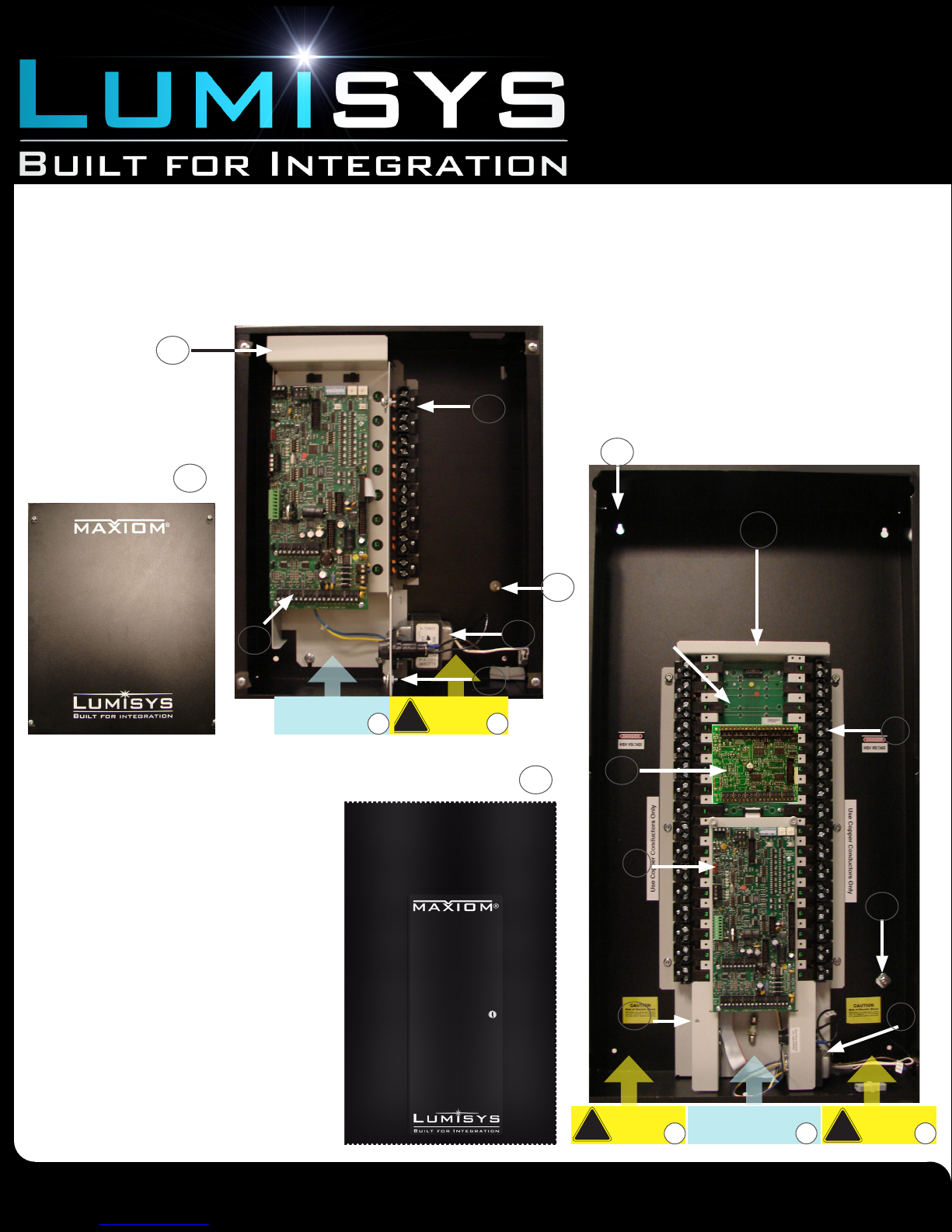
The MX Series comes in ve basic units based upon relay capacities: MX08, MX16, MX32, MX48, and the MX60. Each unit may
contain up to the number of relays indicated. Enclosure sizes for each of the ve units will vary
Pictures of the MX08 and MX32 appear below showing the main components. Check each unit for shipping damage or missing
parts
MX08
13
2
MX32
5
MX08 Cover
8
6
Low Voltage Section
1) Power Supply and fuse
2) LTR Relays
3) High Voltage Sections
4) Low voltage section
5) Contactor space
6) LX5 main processor electronics
7) RIB relay interface board electronics (not
visible on MX08)
8) Surface mounted cover (MX08)
9) LEXP input expansion electronics
10) True lock screw
11) Ground nut
12) Surface mounted cover w/ hinged door
13) Removable, one-piece interior frame
4
MX32 cover
High Voltage
Section
11
13
11
1
3
12
7
2
9
6
11
10
1
0726070122
Due to continuous product improvement, Lumisys reserves the right to change product specications without notice.
High Voltage
Section
www.anybas.com
Lumisys is a Registered Trademark
3
Low Voltage Section
High Voltage
4
Section
Page 5
3
Page 6
Installation Guide
Mx Series
Lighting Relay Panel
Installation
Mounting the MX Series Enclosure
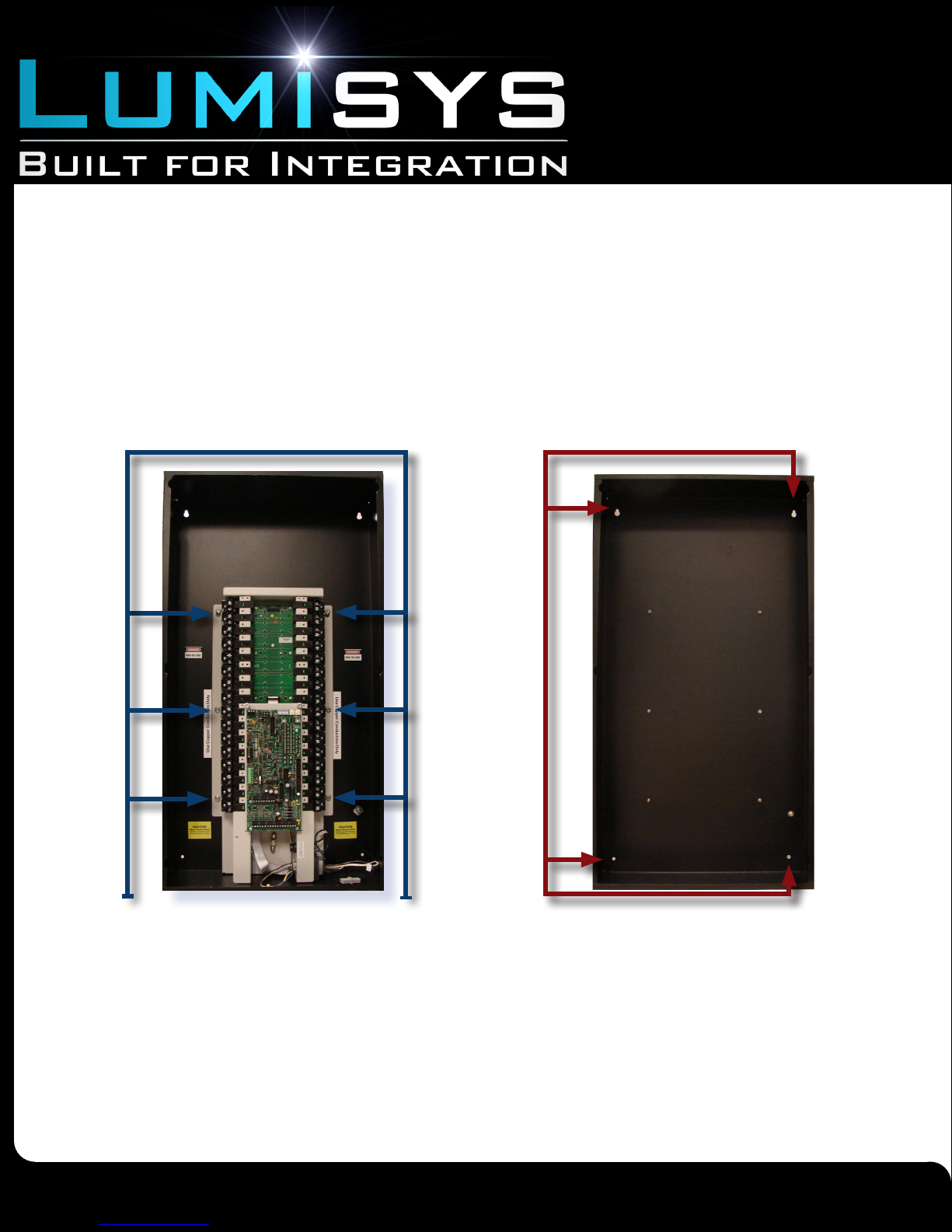
1. Knockout Holes for high and low voltage conduit connections. Below illustrates areas in the MX Series
enclosure where conduit holes for high and low voltage wiring can be made.
a. Remove the interior. If the panel was shipped with electronics installed, remove the interior with electronics until all holes for
conduit are punched and all metal shavings are removed. Metal shavings from drilling could lodge in the electronic components
and cause damage.
The interior is held to the enclosure by ange nuts. See picture below.
Remove the interior and place it away from any work area before drilling holes for conduit.
Interior
ange nuts
(May vary
with panel
size)
Mounting
Holes
(four total)
2. Mount the enclosure with anchors and screws according to picture above .
The picture on the right illustrates the location of the panel mounting holes. The top two mounting holes of the panel enclosure
are keyhole shaped so you can slide the unit over mounting screws, avoiding the need to hold the unit while trying to secure the
mounting screws. Use wall anchors capable of supporting 6lbs for MX08, 16lbs for MX32 and 25lbs for MX60.
If ush mounting, secure the enclosure between the wall studs. Be sure to allow for the thickness of the drywall and 7/8” for the
overhang of the cover so that the panel’s cover will mount ush on the nished wall and away from adjacent panels.
0726070122
www.anybas.com
Lumisys is a Registered Trademark
Due to continuous product improvement, Lumisys reserves the right to change product specications without notice.
Page 6
Page 7
Installation Guide
Mx Series
Lighting Relay Panel
Connecting the Power Supply
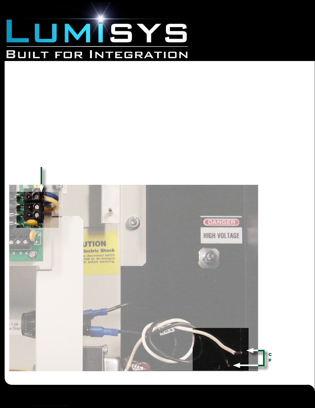
The MX Series can be powered by either 120 or 277VAC. A fuse and dual primary transformer are utilized to offer maximum
exibility during installation. This factory mounted transformer powers the MX Series controller and associated low voltage
coils on the contactors (relays).
1. If connected, remove the power harness from the MX Series controller. See Figure 4 for location of the
harness on the controller. Remove the harness by lifting on the terminal block of the harness.
2. Connect main power to the transformer and fuse assembly. Locate the Common (white) wire and the hot
(black) wire for connection to main power. Figure 4 shows the connectors on the white and black wires.
Power harness
from transformer
(24VAC)
Figure 4
0726070122
Due to continuous product improvement, Lumisys reserves the right to change product specications without notice.
www.anybas.com
Lumisys is a Registered Trademark
Connectors for
power supply
Page 7
Page 8
Installation Guide
Mx Series
Lighting Relay Panel
Connecting the Power Supply
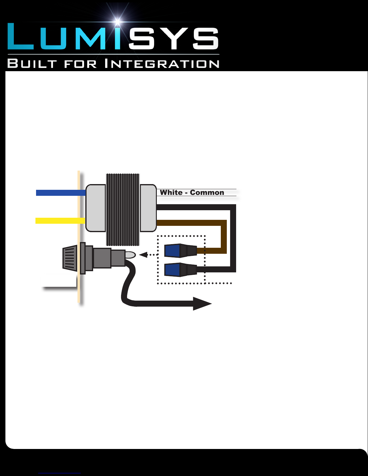
3. Locate wire with correct voltage and connect to fuse. Refer to Figure 5. Power is connected by
choosing the proper voltage wire stemming from the transformer and connecting that wire to the fuse holder.
Each wire is labeled either 120V or 277V. The 120V wire should be black and the 277V wire should be brown.
If this is not the case contact the factory immediately. Each wire is terminated with a spade connector that inserts
over a contact on the fuse holder.
Figure 5
Transformer
Blue
24V
Yellow
Replace with 1.0A
Slow Blow Fuse Only!
White - Common
Black - 120V
Brown - 277V
Fuse
Select either 120 or 277V to HOT
Black - HOT
0726070122
Due to continuous product improvement, Lumisys reserves the right to change product specications without notice.
www.anybas.com
Lumisys is a Registered Trademark
Page 8
Page 9
Installation Guide
!
Mx Series
Lighting Relay Panel
Connecting Branch Circuit Wires
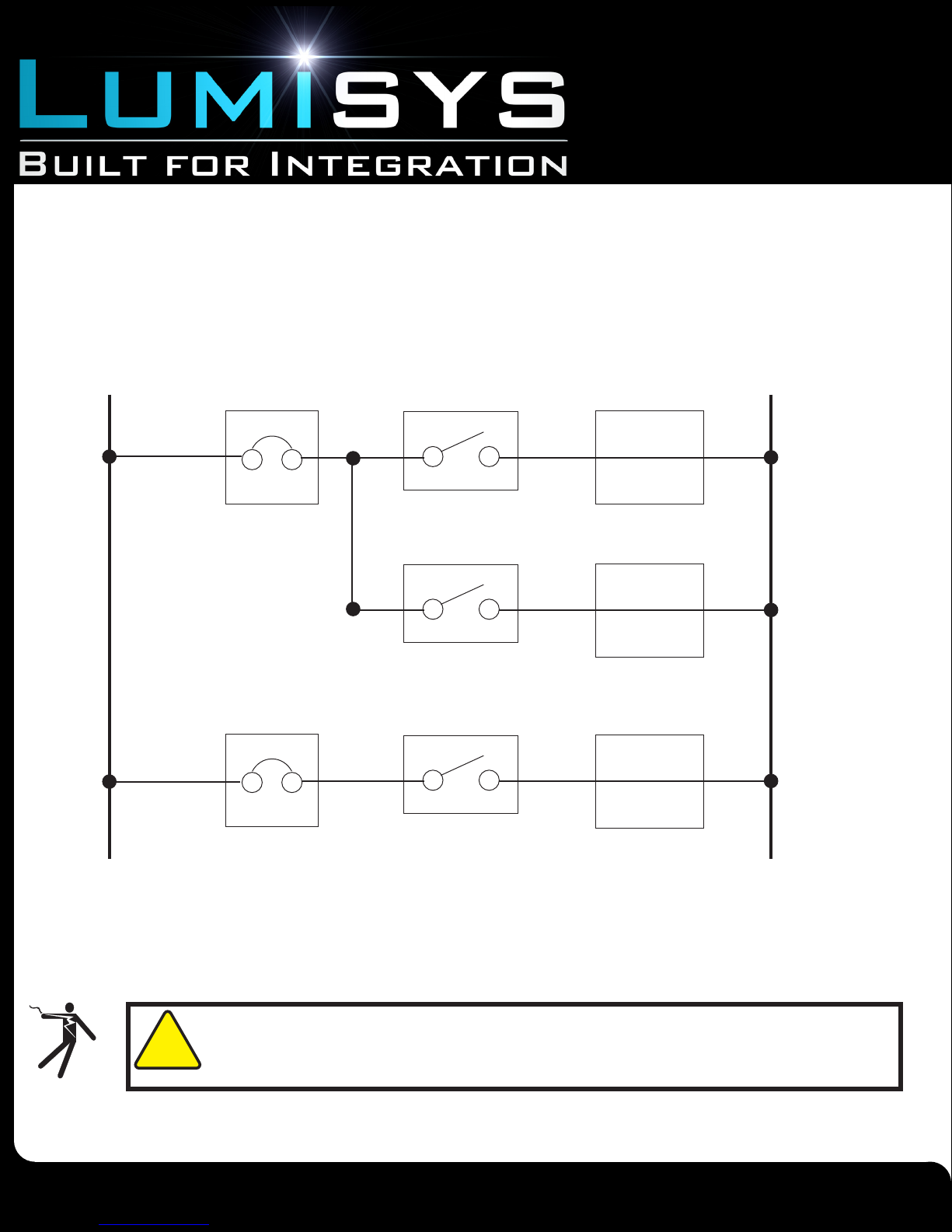
The MX Series panel is equipped with relay capable of switching up to 20 amperes at 277 VAC (Canadian versions, 347VAC). Each
relay can be easily assigned to any of the unit’s zones.
The following gure is a typical wiring diagram. Be sure not to exceed 20 amperes per relay. If the high voltage wiring requires both
120V and 277V on the same high voltage of the panel, a Lumisys MXDIV will be required.
Figure 7
Lighting Load
Maxiom Series
Fuse or Breaker
LTR Relay
Hot
(size per
N.E.C.)
Lighting Load
Maxiom Series
LTR Relay
Lighting Load
Maxiom Series
Fuse or Breaker
LTR Relay
Neutral
WARNING! Disconnect high voltage power to all circuits before connecting them to the
MX Series. Failure to do so could result in serious injury.
Steps 1-2
0726070122
Due to continuous product improvement, Lumisys reserves the right to change product specications without notice.
www.anybas.com
Lumisys is a Registered Trademark
Page 9
Page 10
Installation Guide
Mx Series
Lighting Relay Panel
1. Pull branch circuit wires through high voltage conduit. Note: All wiring should be in accordance with local
regulations and the National Electric Code. Control signal wiring to the low voltage side of the unit should not be run in the
same conduit as line voltage wiring or other conductors that supply highly inductive loads such as generators, motors, or
high voltage circuits located on the high voltage side of the unit.
If 120V and 277V branch wires must be connected to relays on the same side of the panel do not run these wire through the
same conduit. See Overview for high (load) and low (24V) voltage areas of the panel.
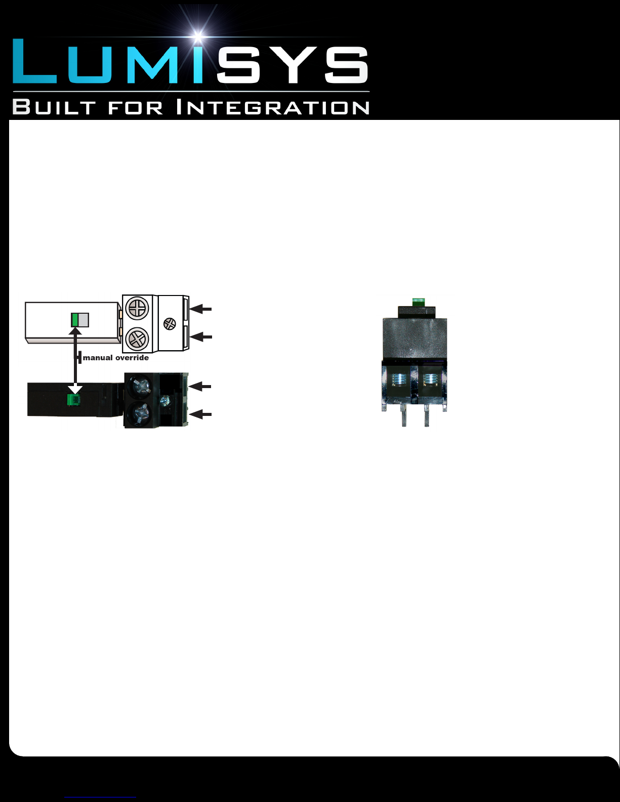
2. Install each branch circuit in one relay as shown in Figure 6. Each branch circuit can be installed in a
relay as shown in Figure 6 below.
Figure 6
Lumisys LTR Relay
Terminal opening to Circuit Breaker
The Lumisys LTR Relay
Terminal opening to Lighting Load
Terminal opening to Circuit Breaker
features manual override and
large gauge terminal block
capable of accommodating
#14-8 AWG or two 10 AWG
wires in each terminal opening.
Terminal opening to Lighting Load
0726070122
Due to continuous product improvement, Lumisys reserves the right to change product specications without notice.
www.anybas.com
Lumisys is a Registered Trademark
Page 10
Page 11
Installation Guide
Mx Series
Lighting Relay Panel
Connecting Switch Inputs
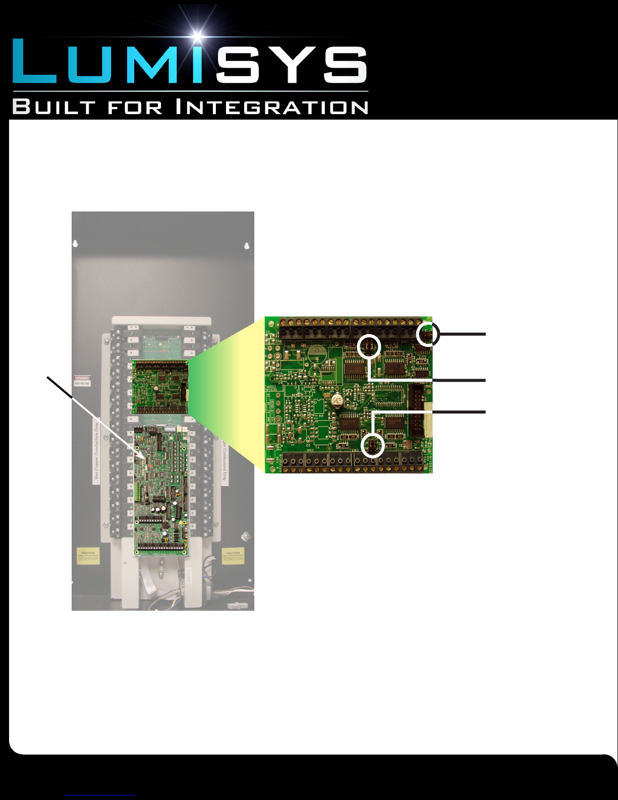
Switch input connections are made on the main processor card, The LX5. The LX5 controller comes standard with 24 programmable
inputs. Input expansion cards (LEXP) increase input capacity and are standard on MX32 panels and higher in increments of 32. See
table in Overview for details. Note LEXP cards are jumper addressed A, B, and C at the factory. Always power down the LX5 before
connecting or removing card.
Figure 8
LEXP
Identication Jumper Pins
J5 (A, B); J6 (C)
LX5
The inputs can be set in software as Momentary on, Momentary off, Momentary on/off, Maintained, Linked, or State change. Each
section has an accompanying jumper that sets whether its associated eight inputs will be up to 24 VDC or dry (0 VDC).
Switch Input Jumpers
1-8 (N, R), and 9-16 (N, R)
Switch Input Jumpers
17-24 (N, R), and 25-32 (N, R)
0726070122
Due to continuous product improvement, Lumisys reserves the right to change product specications without notice.
www.anybas.com
Lumisys is a Registered Trademark
Page 11
Page 12
Installation Guide
!
Mx Series
Lighting Relay Panel
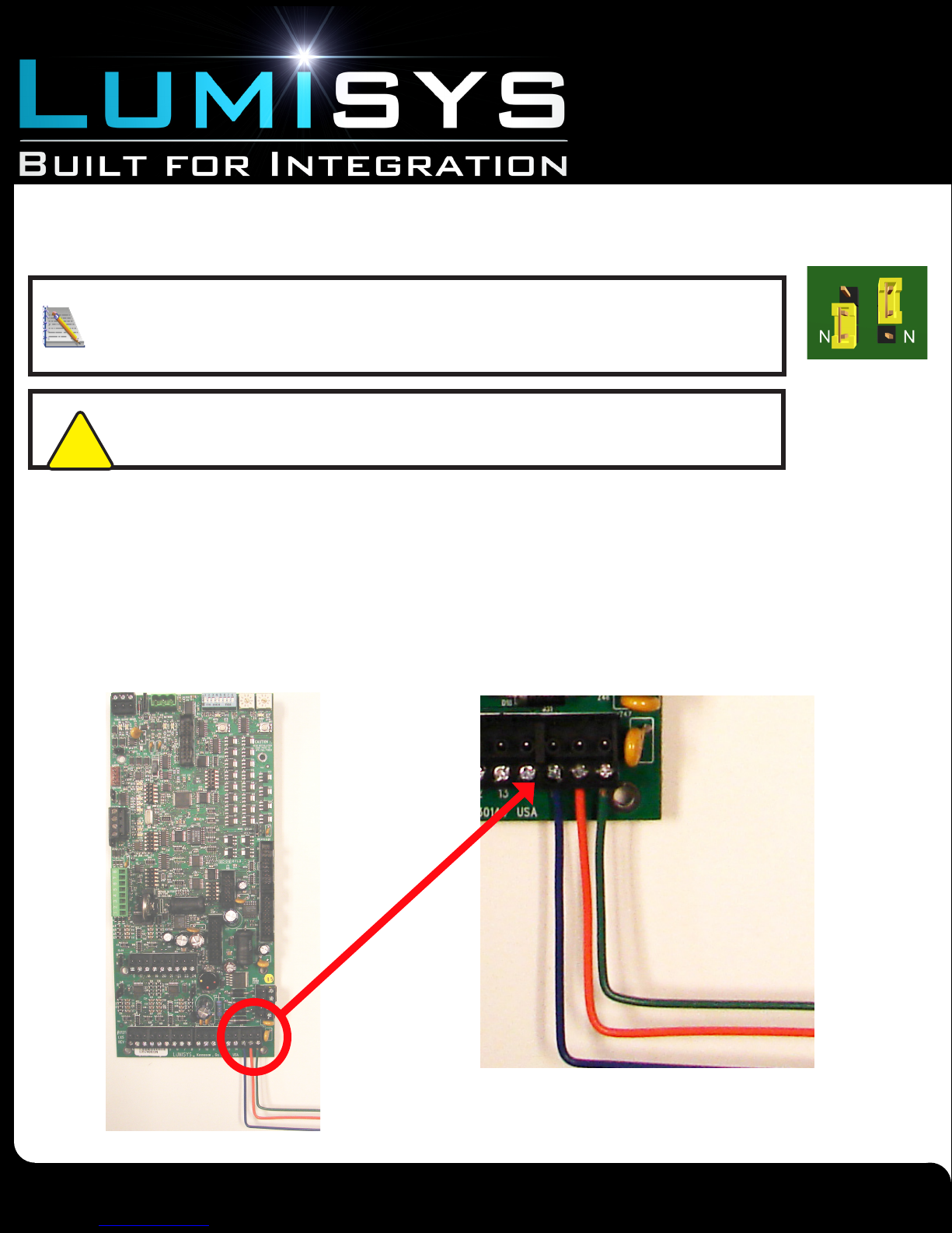
Each jumper set has 3 pins, one of which is labeled “N”. The “N” jumper is for setting the switch inputs for dry
contact. The “up to 24” pin of the jumper pin is not labeled. Figure 9 shows how to place jumpers properly.
The jumper must be set before wiring.
Figure 9
Dry
Position
Up to 24V
Position
Note If one switch input is dry, the entire section of eight switch inputs must also be dry contacts,
and the associated jumper must be in the “dry” position. If one switch input is externally powered up
to 24 VDC, the entire section of eight switch inputs must also be up to 24 VDC, and the associated
jumper must be in the “up to 24” position.
LX5 Switch Input
Jumper Settings
CAUTION! Before handling any components on the circuit board, the installer should be
grounded to prevent damaging the board.
1. Remove power to the controller. Refer to Figure 4. Remove the yellow/blue power harness by lifting on its
terminator block.
2. Set jumpers. See explanations and Figure 8 and Figure 9
3. Connect the switches to the controller. Connect one end of the switch or contact to terminal “G” and the other to
terminal “1-24”. Momentary switches which have both an ON and Off contact will require two switch inputs on the controller. See
Figure 11 for sample wiring diagrams for each input type. Switch input terminal blocks are screw type. Land wires by unscrewing,
inserting the stripped wire, and tightening the screw.
4. Reconnect power to the controller.
*A maximum of 500 feet wire total is allowed, measured from the
switch to the LX5 socket. Use 18-22AWG wire.
0726070122
Due to continuous product improvement, Lumisys reserves the right to change product specications without notice.
www.anybas.com
Lumisys is a Registered Trademark
Page 12
Page 13
Installation Guide
Mx Series
Lighting Relay Panel
Connecting the RS-485 Network
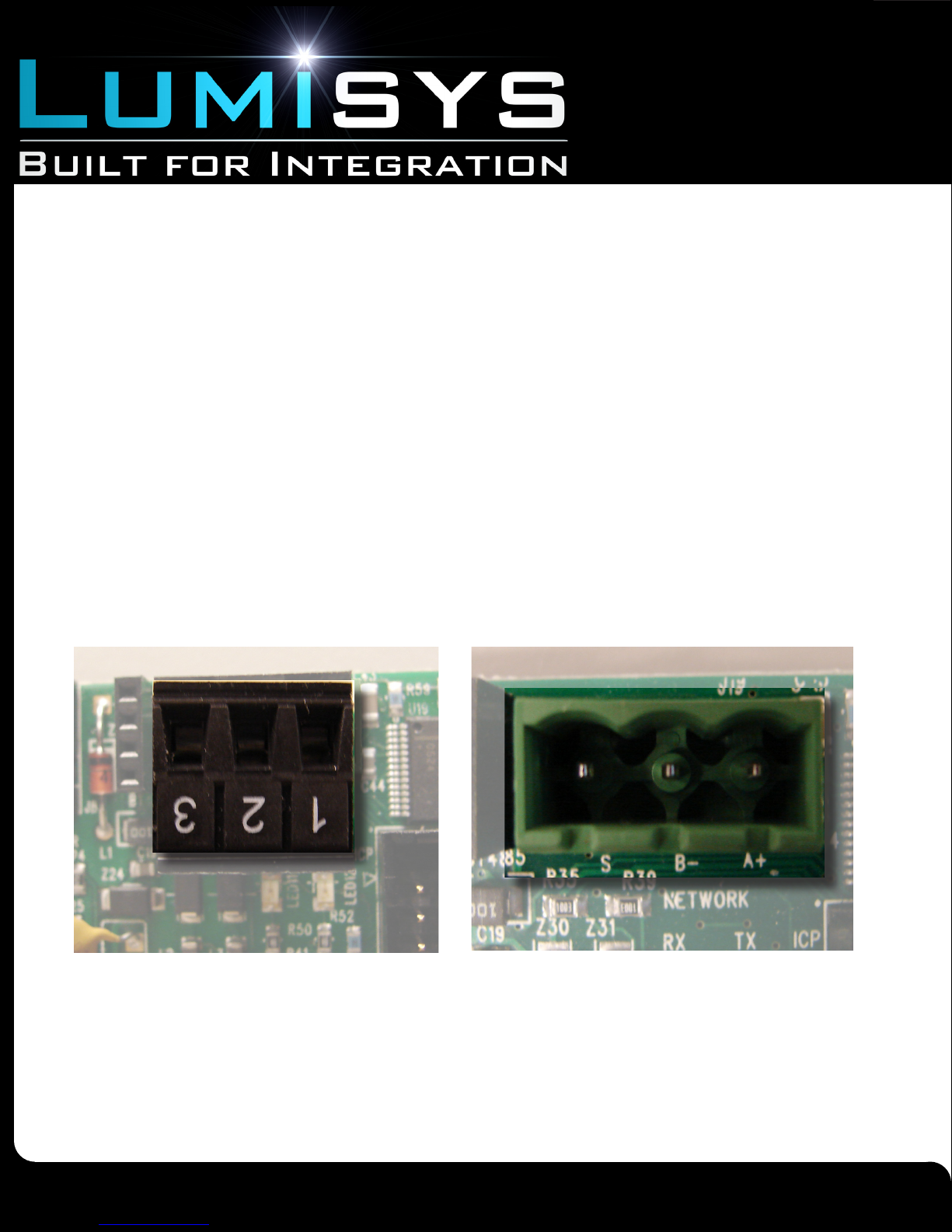
The MX Series is capable of being networked to a Building Automation System over a two or three wire RS-485 communication
network. A terminal block is provided to connect the two communication wires plus the shield wire. (RS-485 wires are not provided
by Lumisys.) Use 18 AWG stranded 600V insulated wire, twisted pair with shield. The RS-485 connection location and labeling is
illustrated in Figure 16.
1. Disconnect power to the MX Series LX5. Refer to Figure 4.
2. Connect incoming and outgoing transmit “+” to “+” on the RS-485 connector. As with switch inputs, a screw type
terminal block is provided.
3. Connect incoming and outgoing transmit “-” to “-” on the RS-485 connector.
4. When a shield wire is used, either splice incoming and outgoing shield wires together or connect to “S” on the
RS-485 connector.
5. Reconnect power to the MX Series LX5.
Figure 16.
RS-485 Connector Input Detail
EIA-485 port w/ terminal block
0726070122
Due to continuous product improvement, Lumisys reserves the right to change product specications without notice.
EIA-485 port showing S, (-), and
www.anybas.com
Lumisys is a Registered Trademark
(+) pins
Page 13
Page 14
Installation Guide
Mx Series
Lighting Relay Panel
Connecting Lumisys LS5 Photocell Inputs
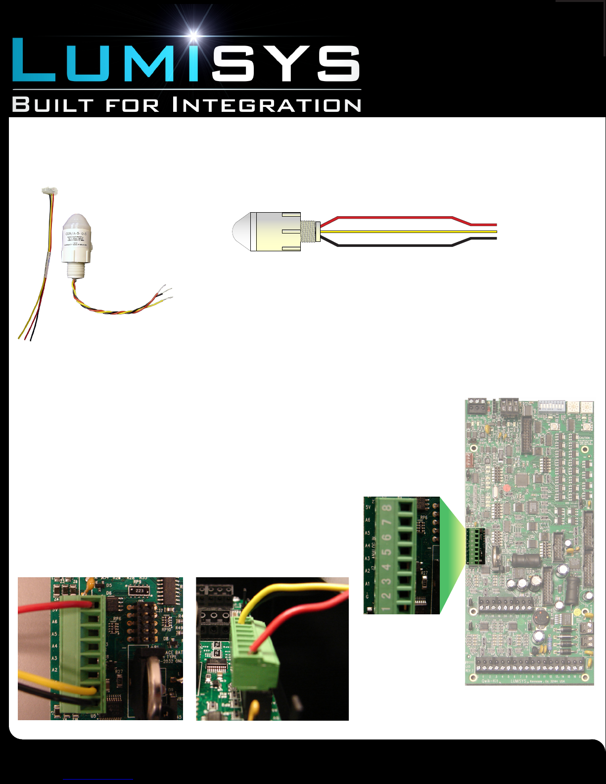
The MX Series Controller comes with six inputs for the LS5 Series Photocells. Each LS5 photocell ships with one pigtail wiring
harness. The contents as shipped are shown in Figure 12. The LS5 photocells have three (3) wires each. Figure 13 gives a wiring
schematic for an example LS5 photocell.
Figure 12
LS5A Indoor Atrium Sen-
The photocell is powered by 5V from the MX Series Controller. The power circuit includes the
Red (5V hot) and the Black (ground) wires. The yellow wire carries the 0-5V input signal from
the photocell which is then scaled to a value used by the LPPK Software. Instructions for
installing the LS5 Photocell follow.
Figure 13
LS5 Photocell
Red
Yellow
Black
LS5 Pigtail Wiring Har-
2. Remove power from LX5.
3. Join red wires from all LS5 sensors into pigtails and
terminate in single termination point marked “5V” on LX5
main board.
4. Connect each yellow signal wire from each LS5 sensor into
individually marked A1-A6 on LX5 main board.
5. Join black wires from all LS5 sensors into pigtails and
terminate in single termination point marked “G” on main
board.
6. Reconnect power to the LX5.
Figure 15
1. After installing the Lumisys LS5 Photocell, splice extension wires to photocell
wires. If possible use the same color wires provided with the photocell. A maximum of 500
feet of wire total is allowed, measured from the photocell to the LX5 socket.
Use 18-22AWG wire.
Figure 14
Location of LS5
Photocell Input
Socket on MX
Series LX5
0726070122
Due to continuous product improvement, Lumisys reserves the right to change product specications without notice.
www.anybas.com
Lumisys is a Registered Trademark
Page 14
Page 15
Installation Guide
Mx Series
Lighting Relay Panel
Adding and Removing LTR Relays
To Remove a LTR Relay
Direct Override Switch**
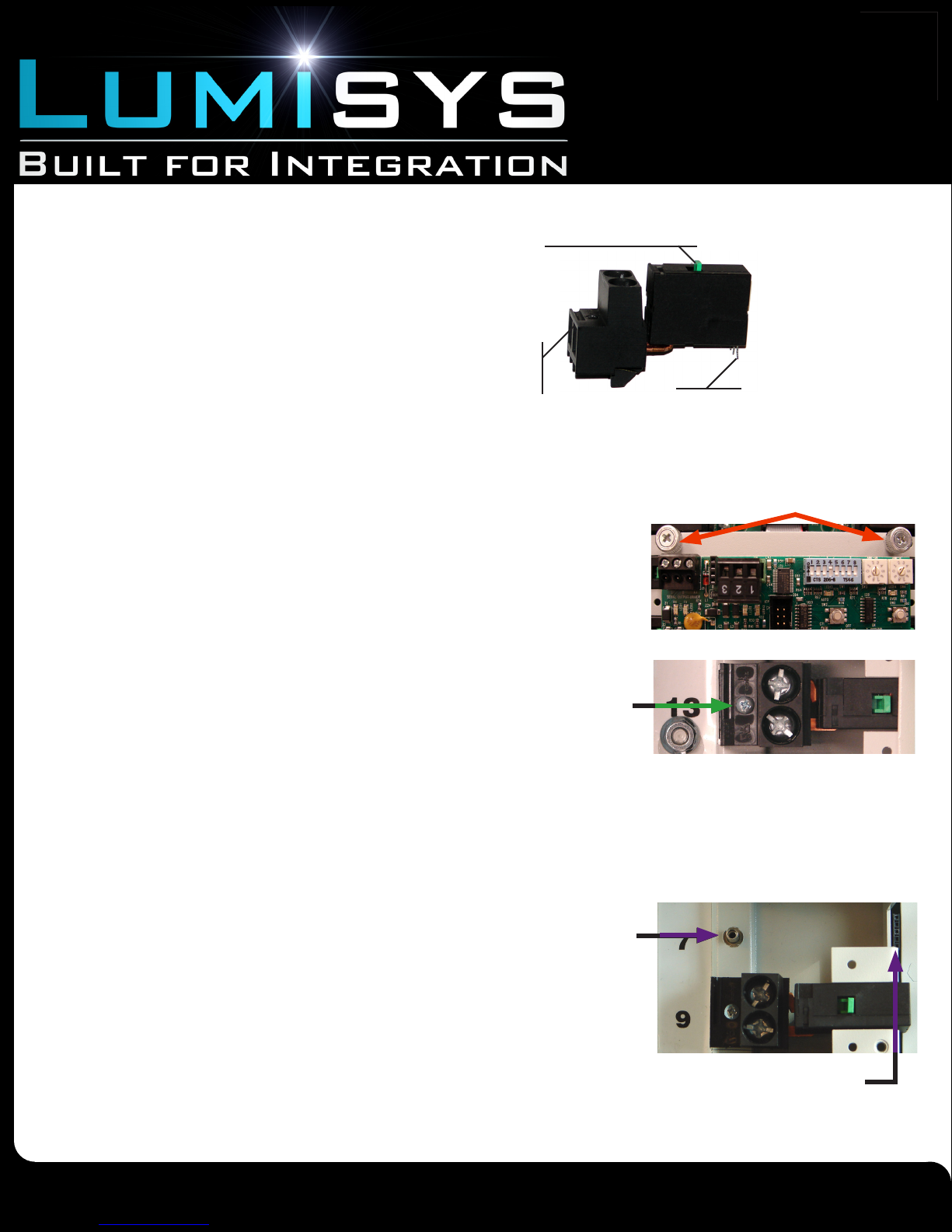
The MX Series contains Lumisys LTR relays which provide the
benet of simple removal and installation. Relay components are
shown in Figure 17. For more information on the LTR relay refer
to the MX Data Sheet obtainable from our website.
1. Disconnect power to the LX5. Refer to Figure 4 of this installation guide for the power connection location to the LX5.
2. If the relay is located behind the LX5, open the LX5 hinged backplate.
Open the LX5 by loosening the two thumbscrews. See Figure 18.
3. Remove branch circuit wires at the relay terminal block.
Refer to “Connecting Branch Circuit Wires” of this installation guide.
Relay
Terminal
Block
Coil Pins
Figure 18
Figure 17
Lumisys LTR
Thumbscrews
4. Remove the relay. The relay is held in place by one screw as shown in Figure 19.
Remove the screw to remove the relay. Pull the relay out in the direction
perpendicular to the panel. Be careful not to damage the relay coil pins when
removing.
5. If a new relay will be placed in the position of the removed relay,
proceed to Step 5 under “To add a relay” below. Otherwise, close the
LX5 backplate.
6. Reconnect power to the LX5. If you are immediately replacing the
removed relay, do not disconnect power.
LTR relay
mounting
screw
To Add a LTR Relay
1. Disconnect power to the LX5. See Figure 4 of this installation guide.
2. If the relay is located behind the LX5, open the backplate by loosening
the two thumbscrews. Refer to Figure 18 for the location of the thumbscrews.
3. Remove the relay blank. The relay blank is factory mounted in
MX Series panels where relay capacity of the unit exceeds the number of
relays ordered. The blank is removed by loosening the one screw.
4. Install the relay. Insert the relay coil pins into the coil pin socket
while seating the terminal block of the relay onto its mounting screw
standoff. Be careful not to bend the coil pins during installation. Fasten
the relay by tightening its mounting screw. See Figure 20.
Mounting
standoff for
LTR relay
terminal
block
Figure 19
Figure 20
5. Install branch circuit wires. Refer to “Connecting Branch Circuit Wires”
of this installation guide.
6. Close the LX5 hinged backplate if necessary, and reconnect power to the LX5.
0726070122
www.anybas.com
Lumisys is a Registered Trademark
Due to continuous product improvement, Lumisys reserves the right to change product specications without notice.
Coil Pin
Page 15
Page 16
Installation Guide
Mx Series
Lighting Relay Panel
Connecting to Digi-Touch Addressable Switch Network
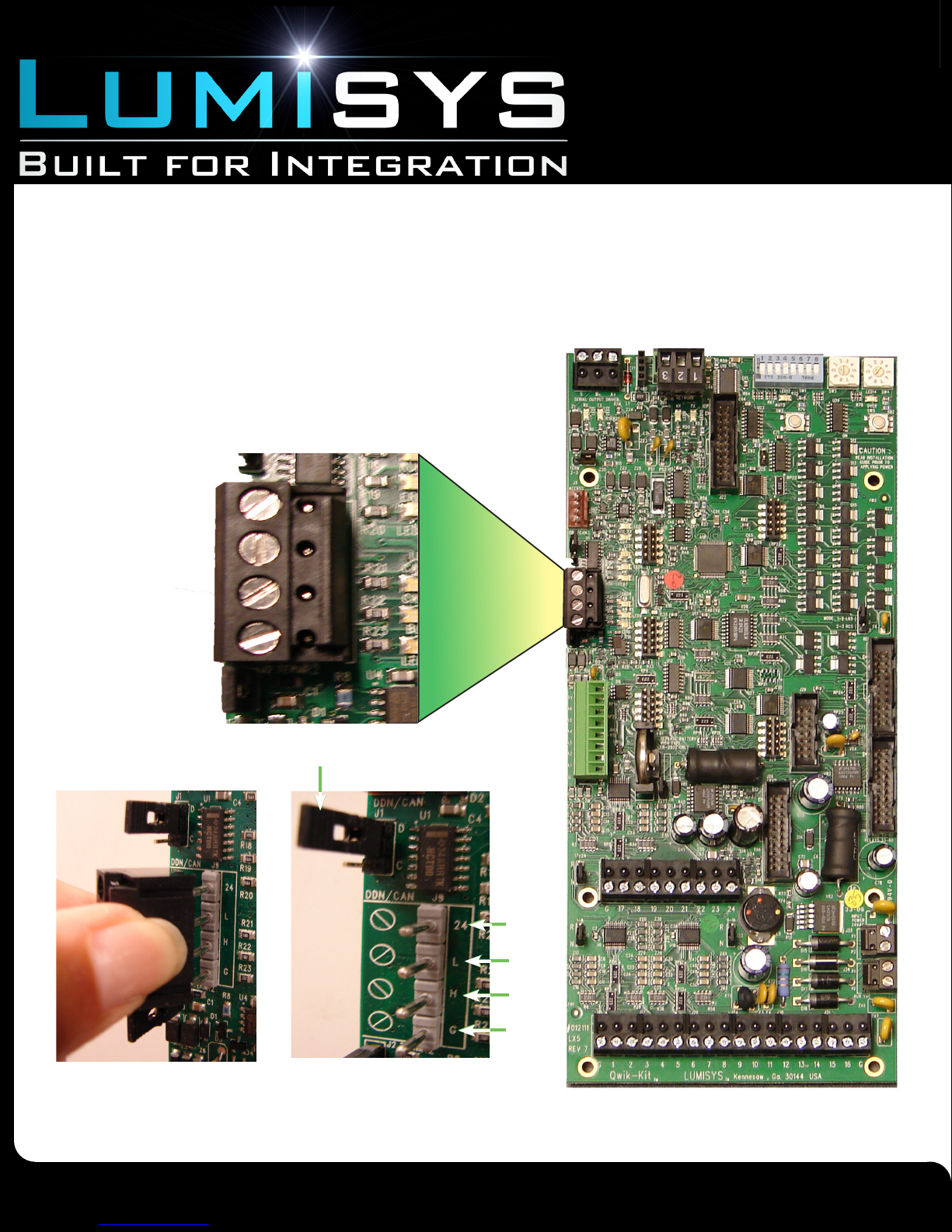
Make all connections before applying power to the LX5 main board. Connect the network of switches to the LX5 port marked DDN/
CAN and set the jumper to DDN (upper 2 pins) as shown in picture below. Remove terminal block to view Pcb markings designating
pins “ 24, I, H, and G”. The LX5 can be used to loop power up to 8 two button DigiTouch switches or up to 16 one-button DigiTouch
switches. For higher quantities of switches, use 24VCD auxiliary power supply. Refer to DigiTouch Installation Guide for details.
Terminal Block
Jumper
0726070122
Due to continuous product improvement, Lumisys reserves the right to change product specications without notice.
24
L
H
G
www.anybas.com
Lumisys is a Registered Trademark
Page 16
Page 17

Installation Guide
Mx Series
Lighting Relay Panel
Terms and Conditions of Sale
AGREEMENT OF SALE: Acceptance by Lumisys, (hereinafter “Seller”) of any order, placed for the goods described on the Acknowledgment, Invoice or Sales Contract hereof shall be subject
to Seller’s Standard Terms and Conditions of Sale and is conditioned upon the Buyer’s acceptance of these Standard Terms and Conditions of sale as stated on this Sales Contract.
TERMS OF CONTRACT: Any terms or conditions of the Buyer ’s order which are inconsistent with these Standard Terms and Conditions shall not be binding on the Seller and shall not be
considered applicable to the sale or shipment of goods covered by this Acknowledgment, Invoice, or Sales Contract. PRICES: Prices are subject to change to the extent permissible under applicable federal law. Sales contracts which call for delivery in the future will be billed at prices in effect at the time of shipment. Shipping weights shown are approximate and subject to change
without notice. Seller shall notify buyer of any signicant changes in weight.
SHIPMENT AND PAYMENTS: All prices are F.O.B. Seller’s plant in Kennesaw, Georgia. No freight is allowed on any shipments. Shipments and deliveries hereunder shall at all times be subject
to the approval of Seller’s Credit Department. Seller may, at any time, require payment in advance or satisfactory security or guarantee that invoices will be promptly paid when due. If Buyer fails
to comply with any terms of payment, Seller, in addition to its rights and remedies but not in limitation thereof, reserves the right to withhold further deliveries or terminate this Agreement, and any
unpaid amount thereon shall become due immediately. Terms of payment shall be as set forth on the face hereof. Unless approved by Seller, all overseas shipments shall require prepayment
by wire transfer or an irrevocable letter of credit from Buyer.
FORCE MAJEURE: Delays or defaults in delivery by Seller of the goods covered by this Sales Contract shall be excused as Force Majeure so far as the same is caused by re, strikes, accident,
war, natural disasters, acts of God, terrorism, explosions, death, vandalism, armed robbery, theft, breakage of machinery, governmental regulation, or any other events which were unavoidable
or caused by events which are beyond the reasonable control of Seller. In no event shall Seller be liable for any consequential, special, or contingent damages on account of any default or delay
in delivery from any Force Majeure event. If any Force Majeure event occurs which may affect Buyer’s goods, Seller shall give prompt oral and written notice of its Force Majeure declaration to
Buyer within 7 days or as soon as is practicable.
NON-CANCELLATION: Orders are not subject to suspension, reduction, or cancellation, except on terms that will indemnify Seller against loss. SPECIFICATIONS: Seller relies on specications and other data furnished by the Buyer, architect, contractors, and/or consulting engineer in all phases of the work covered by this Acknowledgment, Invoice or Sales Contract. Seller shall
be responsible to check quantities only. Alterations, changes in specications, approval of samples, and/or changes in delivery shall not be binding upon Seller unless approved by Seller in
advance. In the event Buyer asks Seller to perform design or engineering work for any and all phases of the work covered by this Acknowledgment, Invoice or Sales Contract, Seller shall not be
responsible for any damages claimed by the Buyer as a result of alleged errors or defects in such design or engineering work except for gross negligence on the part of Seller.
WARRANTY AND LIMITATION OF LIABILITY: Seller warrants that the goods supplied by it have been manufactured in accordance with its standard manufacturing practices, are non-defective
and conform to the contract or catalog description for such goods. Except as stated herein, Seller makes no express warranty with respect to goods supplied by it and Seller makes no implied
warranties of suitability or tness for any particular purpose. Unauthorized or unapproved modications or alterations of such goods without the express written approval of Seller shall void all
warranties and indemnities granted herein. To satisfy its indemnity and warranty obligations, Seller will, at its sole option, credit, repair or replace, any goods supplied by it which its examination shall disclose to its satisfaction are defective in workmanship or material, and are returned to it within two years from the date of shipment. Any claim not made within this period shall be
conclusively deemed waived by Buyer. Seller shall not be liable for any consequential, special, incidental, punitive or contingent damage or expense arising directly or indirectly from any defect
in its goods or from the use of any defective goods or otherwise arising out of this Contract or any purchase order. The remedies set forth herein shall constitute the exclusive remedies available
to Buyer for Seller’s indemnity and warranties and are in lieu of all other remedies that would otherwise be available to Buyer.
Warranty and technical support on Lumisys products are only available after payment has been received in full.
RETURNS: Material returned for credit is subject to a 10% restocking charge. Freight or other costs incurred in restocking will be added. Returns resulting from errors by the Seller will not be
subject to the charge. Returned materials shall be received in condition for resale as new equipment to qualify for credit. Returned materials must be returned to the Seller within 30 days of
receipt and shall only be accepted with prior authorization.
SELLER RESERVES THE RIGHT TO SUBSTITUTE MATERIALS USED IN CONSTRUCTION OR EQUIPMENT SOLD PROVIDED SAID SUBSTITUTION DOES NOT MODIFY THE OPERATIONAL CHARACTERISTICS OF THE EQUIPMENT SOLD.
THESE TERMS OF SALE MAY BE MODIFIED WITHOUT NOTICE. THE TERMS OF SALE IN EFFECT AT THE TIME OF SALE SHALL APPLY. THE SELLER AS REFERRED TO IN THE
TERMS OF SALE IS Lumisys.
CLAIMS: Claims for shortages of goods or for mistakes or errors in billing must be presented within forty-ve (45) days from the date of goods; and must state the packing slip number and
container number applicable to the claim. Any claim not so presented shall be conclusively deemed waived.
TAXES: Any federal, state, local or government tax or charge on the sale, shipment, or installation of the goods covered by the Acknowledgment, Invoice or Sales Contract, shall be added to
the price and paid by Buyer or, in lieu thereof, the Buyer shall furnish Seller with tax-exemption certicates acceptable to the taxing authority. Buyer agrees to reimburse and save Seller harmless from all such state and local taxes, including interest and penalties thereon, which may at any time be payable to any governmental unit with respect to the sale of any goods covered by
this Acknowledgment, Invoice or Sales Contract.
CREDIT BALANCE: Any credit memos granted to Buyer from Seller arising out of returned goods or other circumstances, which are not subsequently requested or applied to the purchase of
other goods from Seller within twelve months from the date credit was granted, shall become the property of Seller.
APPLICABLE LAW: All questions arising out of this Acknowledgment, Invoice or Sales Contract, which shall be deemed a Georgia contract, shall be governed by the laws of the State of Georgia. Venue for any disputes arising out of this agreement shall be in Georgia. All disputes arising out of this agreement shall be resolved in the following fashion: the parties shall rst engage
in good-faith negotiation. If the parties are unable to settle their claims through good-faith negotiation, the parties shall attempt to resolve their dispute through mediation by an agreed upon
mediator. Lastly, if mediation fails, the parties shall be subject to binding arbitration by an agreed upon arbitrator who is a member of the American Arbitration Association. The prevailing party
in any arbitration or other legal action arising out of this agreement, and/or these terms and conditions of sale, shall be entitled to indemnication of all its attorneys’ fees, litigation expenses,
and costs from the losing party.
EXCLUSIVE TERMS: This Acknowledgment, Invoice or Sales Contract, which includes these Standard Terms and Conditions, shall constitute the nal and binding contract between the parties
and shall take precedence over any other terms and conditions from the Buyer. Any changes or deviations from this Acknowledgement, Invoice or Sales Contract must be in writing and mutually
agreed to by Buyer and Seller.
LIMITATION FOR SUITS: Any controversy or claim arising out of, or relating to, this Acknowledgment, Invoice or Sales Contract, or the breach thereof, must be commenced within two (2) years
after the cause of action accrued.
0726070122
Due to continuous product improvement, Lumisys reserves the right to change product specications without notice.
www.anybas.com
Lumisys is a Registered Trademark
Page 17
 Loading...