

Page 1

LSDT
API
DYNAMIC LINK LIBRARY
REFERENCE GUIDE
LUMISYS
Page 2
/6'7$3,'\QDPLF/LQN/LEUDU\
5HIHUHQFH*XLGH
315HY
0DUFK
Lumisys, Inc.
225 Humboldt Court
Sunnyvale, CA 94089
Page 3
/6'7$3,'\QDPLF/LQN/LEUDU\5HIHUHQFH*XLGH
BBBBBBBBBBBBBBBBBBBBBBBBBBBBBBBBBBBBBBBBBBBBBBBBBBBBBBBBBBBBBB
7 $%/(2)&217(176
BBBBBBBBBBBBBBBBBBBBBBBBBBBBBBBBBBBBBBBBBBBBBBBBBBBBBBBBBBBBBB
TABLE OF CONTENTS..........................................................................................................................1
1. INTRODUCTION.............................................................................................................................4
1.1 Document Notation......................................................................................................................4
1.2 Terminology................................................................................................................................4
1.3 Related Documents.....................................................................................................................4
1.4 Environment Requirem ents.........................................................................................................4
1.4.1 Minimum Hardware.............................................................................................................4
1.4.2 Operating S ystems.............................................................................................................4
1.4.3 CPU Resources Used by the Data Control Board................................................................5
1.4.4 LSDT Device Driver (DCB Interface Only)........................................................................... 5
2. LUMI S CAN LSDT ARCHITE CTURE...............................................................................................6
2.1 Interfaces....................................................................................................................................6
2.1.1 DCB Interface.....................................................................................................................6
2.1.1.1 DCB Memory Mapping....................................................................................................6
2.1.2 SCSI Interface....................................................................................................................7
2.2 Technical Featur e s......................................................................................................................7
2.2.1 Scan Mode and Pixel Resolut ion.........................................................................................7
2.2.1.1 Fixed..............................................................................................................................7
2.2.1.2 Variable..........................................................................................................................7
2.2.2 Pixel Depth.........................................................................................................................7
2.2.3 Pixel Format .......................................................................................................................8
2.2.4 Averaging Modes................................................................................................................8
2.2.5 Shifted Dynamic Range Mode.............................................................................................8
2.2.6 User LUT.................................................................................................................. ..........8
2.2.7 6-Sheet Film Feeder ...........................................................................................................9
2.2.8 Bulk Autoloader Film Feeder.............................................................................................10
2.2.9 Barcode Reader................................................................................................................10
2.2.10 Film Present Sensor..........................................................................................................10
2.3 Di gitizer Capabilities..................................................................................................................12
3. SOFTWARE FUNCTIONS............................................................................................................13
3.1 Gener al Setup Functions...........................................................................................................13
3.2 Special Operation Functions......................................................................................................13
3.3 Scanning Functions...................................................................................................................13
3.4 Post-Scan Functions.................................................................................................................13
3.5 Miscellaneous Functions...........................................................................................................14
3.6 Di agnost ic Functions.................................................................................................................14
3.7 Compat ibi l it y Fu n ctions.............................................................................................................14
4. SOFTWARE APPLICATIONS.......................................................................................................15
4.1 Linking LSDT Software Functions..............................................................................................15
4.2 Sample Code............................................................................................................................15
4.2.1 Very Simple Example........................................................................................................15
4.2.2 Better Example.................................................................................................................16
4.2.3 Finding Pixels Per Line .....................................................................................................18
5. LIBRARY FUNCTIONS REFERENCE ..........................................................................................19
5.1 LS_ChangeTimer......................................................................................................................19
5.2 LS_CloseDevice........................................................................................................................19
5.3 LS_DiagnosticScan...................................................................................................................20
5.4 LS_DriverStateString.................................................................................................................20
5.5 LS_ErrorString..........................................................................................................................21
5.6 LS_FeedFilm.............................................................................................................................21
P/N 0068-105, Rev. 08 Page 1 of 53 March 9, 1999
Page 4

/6'7$3,'\QDPLF/LQN/LEUDU\5HIHUHQFH*XLGH
5.7 LS_FileC o p y.............................................................................................................................22
5.8 LS_GetAllTimers.......................................................................................................................22
5.9 LS_GetApiInfo...........................................................................................................................23
5.10 LS_GetDataCount.................................................................................................................23
5.11 LS_GetDriverHandle.............................................................................................................23
5.12 LS_GetDrvInfo......................................................................................................................24
5.13 LS_GetDrvVersion................................................................................................................25
5.14 LS_GetImageWindow ...........................................................................................................25
5.15 LS_GetLastSC S IEr ror...........................................................................................................25
5.16 LS_GetPixelsP e rL in e............................................................................................................25
5.17 LS_GetStatus........................................................................................................................26
5.18 LS_GetTimer........................................................................................................................26
5.19 LS_GetVersion ......................................................................................................................27
5.20 LS_isBarCodeValid...............................................................................................................27
5.21 LS_isFilmPres e n t..................................................................................................................27
5.22 LS_LoadCalibrationTable......................................................................................................28
5.23 LS_LoadCorrectionLookUpTable...........................................................................................28
5.24 LS_LoadLookUpTable...........................................................................................................28
5.25 LS_LoadLut ..........................................................................................................................29
5.26 LS_MapImageData ...............................................................................................................30
5.27 LS_MapImageWindow..........................................................................................................31
5.28 LS_ModelNameString...........................................................................................................31
5.29 LS_Motor..............................................................................................................................32
5.30 LS_OpenDevice....................................................................................................................32
5.31 LS_PixelDepth S tring.............................................................................................................32
5.32 LS_PixelFormatString...........................................................................................................33
5.33 LS_ReadBarCode.................................................................................................................33
5.34 LS_ReadCalibrationTable .....................................................................................................34
5.35 LS_ReadCorrectionLookUpTable..........................................................................................34
5.36 LS_ReadDiagnostic ..............................................................................................................34
5.37 LS_ReadImageIntoBuffer......................................................................................................35
5.38 LS_ReadImageIntoFile..........................................................................................................36
5.39 LS_ReadImageIntoFile_Fast.................................................................................................36
5.40 LS_ReadImageToPointer......................................................................................................37
5.41 LS_ReadLookUpTable..........................................................................................................37
5.42 LS_ReadLut..........................................................................................................................38
5.43 LS_Register C md...................................................................................................................39
5.44 LS_ResetD ri verVa riables......................................................................................................39
5.45 LS_ResetH a rdw a re...............................................................................................................39
5.46 LS_ResetSc a n......................................................................................................................40
5.47 LS_ScanModeString.............................................................................................................40
5.48 LS_SetAverag ingMode .........................................................................................................40
5.49 LS_SetDevNu m....................................................................................................................41
5.50 LS_SetLase r Mode ................................................................................................................41
5.51 LS_SetNextSca n Params.......................................................................................................41
5.52 LS_SetPMTvol ta ge ...............................................................................................................42
5.53 LS_SetSDRMod e..................................................................................................................42
5.54 LS_SetTrim...........................................................................................................................43
5.55 LS_StartFilmS c a n.................................................................................................................43
5.56 LS_StartFilmS c a n N o C L U T....................................................................................................44
5.57 LS_StartMotor.......................................................................................................................45
5.58 LS_StatusOfLastScanString..................................................................................................45
5.59 LS_StopMotor.......................................................................................................................45
5.60 LS_StopScanEject................................................................................................................46
5.61 LS_UnMapImageWindow......................................................................................................46
5.62 LS_WriteMemory..................................................................................................................46
APPENDIX A: LUMISYS IMAGE HEADER FORMAT .........................................................................47
APPENDIX B: FUNCTION ERROR CODES........................................................................................48
P/N 0068-105, Rev. 08 Page 2 of 53 March 9, 1999
Page 5

/6'7$3,'\QDPLF/LQN/LEUDU\5HIHUHQFH*XLGH
APPENDIX C: SCSI ERROR CODES..................................................................................................49
P/N 0068-105, Rev. 08 Page 3 of 53 March 9, 1999
Page 6

/6'7$3,'\QDPLF/LQN/LEUDU\5HIHUHQFH*XLGH
1. INTRODUCTION
This document describes the function s in the LSDT Application Programmer’s In terface Dynamic Link Library
(LSDTAPI.DLL). They provide a Windows 3.x / Windows 9x / Windows NT high-level application interface to
LSDT digitizers. Refer to the LSDT Software Functions Library Reference Guide (P/N 0066-022) for information
on DOS high-level application interface functions to th e LSDT digitizers.
1.1 Document Notation
ALL_CAPS_IN_ITALICS – den otes a #DEFINE value. Almost all of the #DEFINEs you will need are in the
following header files:
• LS_TYPES.H
Data types and defines used by the librar y.
• LS_DT.H
Defines , const an ts and str uctures u s ed by the library, LSDT errors, scan modes, LSDT stat es
(a.k.a. "pha ses"), and mi scell aneous defines and structures.
• LS_API.H
API function declarations for Windows. They are the same for both Win16 and Win32.
If you don’t fin d what you need in these two files, then look in one of the other in clude files in \INCLUDE (Win16)
or \INC (Win32).
1.2 Terminology
• DACQ Data Acquisiti on Boar d in the LSDT digitiz er
• DCB ISA-based Data Control Board located in the PC
• Host PC cont aining the DCB
• Win16 for Microsoft Windows 3.1, Windows For Workgroups 3.11, Windows 95, or
Wind ows 98
• Win32 f or Microsoft Windows 95, Wi ndows 98, or Windows NT
1.3 Related Documents
LSDT Software Functions Library Reference Guide P/N 0066-022
LSDT API Dyn amic Link Library Reference Guide P/N 0068-105
LUMISCAN 20 Operator’s Reference Guide P/N 0069-384
LUMISCAN 50 / 75 / 8 5 Operator’s Reference Guide P/N 0061-494
ACR-2000 Operator’s Reference Guide P/N 0070-711
LUMISCAN LSDT Film Digitizer / CR Rea der Configuration Guide P/N 0071-434
1.4 Environment Requirements
1.4.1 Minimum Hardware
• 486DX2/66 MHz (or faster, depen ding upon Windows Operating System)
• 8 MB RAM (or more, depending upon Windows Operating System)
1.4.2 Operating Systems
• Windows 3.1 / Windows For Workgroups 3.11 (using 16-bit driver w/ DCB)
• Windows 95 / Win dows 98 (using 16-bi t driver w/ DCB or 32-bit w/ SCSI)
• Windows NT (u s i ng 32-bit driver w/ DC B or 32-bit w/ SCS I)
P/N 0068-105, Rev. 08 Page 4 of 53 March 9, 1999
Page 7

/6'7$3,'\QDPLF/LQN/LEUDU\5HIHUHQFH*XLGH
1.4.3 CPU Resources Used by the Data Control Board
• Address Space
32-Kbyte (0x8000 Hex) window
starting address 0xA0000-0xE8000 (switch selectable)
0xD0000 – factory setting
• IRQ
3, 4, 5, 6, 7 (jumper selectable)
5 – factor y s e tting
• I/O Address
0x100-0x11F, 0x120-0x13F, 0x140-0x15F or 0x160-0x17F (switch selectable)
0x100 – factory setting
NOTE: Older DCB models only supported addresses beginning at 0x100 and 0x120.
• DMA
None
• Bus Type
8- or 16-bit ISA
1.4.4 LSDT Device Driver (DCB Interface Only)
For all Win16 systems , the DOS LS DT device dr iver "LSD TVxxx.COM " mu st be instal led on the host. At the
command line or in AUTOEXEC.BAT, enter "LSDTVxxx" (where xxx specifies version number). This must be
installed prior to starting Windows. For Windows 95 / Windows 98, the dr iver must be loaded by
AUTOEXEC.BAT. The driver switch option s are descr ibed in the LUMISCAN Oper ator’s Referen ce G u ides.
For Win dows NT, the LSDT device driver is automatically loaded. It may be manually loaded by using
“Device s” (in “Control Panel”) or by typing “NET START LSDT” from a comm and promp t. S ee RE AD M E.TXT
for installa tion instructi ons for the Windows NT LSDT device driver, LS D T.SYS.
Digi tizers with a SCSI int erface do not use th e LS DT device driver.
P/N 0068-105, Rev. 08 Page 5 of 53 March 9, 1999
Page 8

/6'7$3,'\QDPLF/LQN/LEUDU\5HIHUHQFH*XLGH
2. LUMISCAN LSDT ARCHITECTURE
The LumiScan DeskTop (LSDT) family con sists of film digitizers and CR phosphor plate readers using either
a scanning laser beam and light collection cylinder or a CCD array with a proprietary illumination system. A pinch
roller system is used to transport the medium being scanned.
NOTE: In this document, when we use the term “film”, we mean a somewhat gen eric reference to “whatever is
being scan ned”. Currentl y, several type s o f media are used in var i ou s d igitiz er s and reader s:
• Film (ph otographic negatives) LS20 CCD Digitizer
LS50, LS75, LS85 Laser Digitizers
• Phosphor-coated CR plates ACR-2000 CR Reader
• Fluorescent CR Test patterns ACR-2000 CR Reader
NOTE: Ad d itionally, in this docum en t, we use the t erm “digitizer” t o mean a somewhat generic reference to either
a (film) digitizer or a (CR) reader.
An LSDT digitizer houses a Data Acquisition Board (DACQ) which is connected to a Data Control Board
(DCB) l oca ted in a host computer via a shielded 37 - pin cable (for the SCSI in terface, the DCB i s l oca ted in sid e the
digitizer). All operations are controlled by the DCB. Once a scan is initiated, the data acquisition is automatic,
requirin g no intervention. During a scan operation image data is written into a circular buffer in the image memory
on the DCB. On digitizers with enough memory to hold a complete image it is possible to let the scan complete
before tran sfer image da ta out of DCB image memory. However, if the image size is gr eater than the circular buffer
size, then the situation is en tirely different:
NOTE: For Images Greater Than the DCB Memory Size
The pinch roll er med ia tran s p ort system does N O T allow the scan operation to stop before the end of the
media. Therefore, the host application MUST read the imag e da ta out of th e circular bu ff er as th e dat a is acquired
or the buffer will even tually overflow. When the DCB image memory circular buffer is full it wraps and begins
overwriting the oldes t data. If the ho st application has not read the old data when t he image memory wraps, a
“DATA_LOST” error is generated and data from the scan will truly be l ost.
2.1 Interfaces
2.1.1 DCB Interface
In thi s interface, the DCB is an ISA card in th e host com p uter. It con nects to the digitizer via a shielded 37 - pin
cable. The car d itself is a PC/AT ISA 8-bit board requiring a 32K byte memory window (0xA0000-0xE8000) and
32 bytes of I/O space based at either 0x100, 0x120, 0x140 or 0x160 (older DCB boards only supported address at
0x100 and 0x120). An interrupt resource (IRQ) is also used and can be set to 3, 4, 5, 6 or 7. The 32K memory
window is for access to t he image memory and can be placed on any 32K boundary within the 0xA0000-0xE8000
address space. The DCB is populated with 4, 12 or 16 Megabytes of memory depending on the model of digitizer
that wi ll be conn ected.
The DCB is contr olled by the LSDT device driver running on the host computer . The LSDT Application
Programmer's Interface Dynamic Link Library (LSDTAPI.DLL) provides a run-time Windows application interface
to the LSD T digitizer (via the LSDT devi ce d river or SCSI int er face). The library contain s al l the funct ions needed
by a Windows application program to control th e LSDT family of digitizers. DOS pr ograms use the LSDT Software
Functions Library (LSDTFCNS.LIB) which provide substantially th e same functions.
Neither dir ect interface to the D C B n or direct interface t o the DOS/Windows or Windows NT driver s are
supported by Lumis ys.
2.1.1.1 DCB Memory Mapping
The 32 KB ad dress space can be map ped into th e application’s ad dress space. This allows dir ect access to the
image d ata. The fun ction LS_Ma p ImageWindow is used to add the DC B mem ory to the app licati on s ad dress spa ce;
LS_UnMapImageWindow is used to remove it. The function LS_GetImageWindow returns the physical address of
the DCB m emory, which is called by the LS_ M apImageWindow function. Th e function LS _ M apImageData cau s es
P/N 0068-105, Rev. 08 Page 6 of 53 March 9, 1999
Page 9

/6'7$3,'\QDPLF/LQN/LEUDU\5HIHUHQFH*XLGH
the dr iver to program the DC B hardware to place th e image data specified by byte offset from the beginning of th e
image, into the DCB memory window. All mapping must be on 32K boundaries.
2.1.2 SCSI Interface
In this inter face, the DCB is located in side the digitizer. It is part of a single board computer, also inside the
digit izer, which in turn con nects t o a h ost comput er via a stan dard SCSI ca bl e.
2.2 Technical Features
When you start a scan ( LS _ S tartFilmScan ), there are four things you must s p ecify:
• Scan Resolution Mode Fixed or Variable number of pixels per inch
• Pixel Resolution Pixels Per Line (PPL) or Pix el s Per Inch (PPI )
• Pixel Depth 8 or 12 bits per pixel
• Pixel Format LSB or MSB first
Additionally, there are other settable features such as avera gi ng, shifted dynamic ran ge, lookup tables, etc.
2.2.1 Scan Mode and Pixel Resolution
There are two scan modes: FIXED_RESOLUTION an d VARIABLE_RESOL UTION. You specify which
when you start a fi lm scan. Note th at all digitizer s have minimu m and maximum “pixel s per line” and “p ixels per
inch” resolutions. These minimums and maximums vary according to the digitizer type, and in many cases, to the
width of the film being scanned.
2.2.1.1 Fixed
FIXED_RESOLUTION means that the pixel resolution (or “pixels per inch”) will be the same regardless of
film width. The resolution will be determined by the “pixels per inch” argument passed to th e LS_xxx function s.
The number of pixels per line returned is determined by th e film width with a maximum being imposed by the
digitizer model.
When th e r eq uested p ix els per in ch times the fi lm width ca u s es the total n umber of pix e l s p er line to exceed the
digitizer model har dware limits, an error (PIXELS_PER_LINE_OUT_OF_RANGE) is returned and the film is
reversed out of the digitizer. However, if the film width is just a little too large ( < 1 inch), then the scan is
performed by trimming the edges (instead of returning an error).
2.2.1.2 Variable
VARIABLE _ RE S O LUTION m eans tha t the pixel resolut ion (or “pixels per inch”) wi ll vary accordin g t o th e
width of the film. The resolution will be determined by the “pixels per line” (argument passed to the LS_xxx
function s) over the entire width of the film. So regardless of film width, each scanned line will contain PPL pixels.
For example, if th e pixels per line is set to 1024 and the scan mode is variable, then a scanned line of film will
contain 1024 pixels. If the width of film is 14", the pixel resolution will be 1024 ÷ 14 = 73 pixels/inch. If the film
width is only 8 inches, a scanned line of film will still contain 1024 pixels; however, the pixel resolution will be
higher: 1024 ÷ 8 = 128 pixels/inch.
NOTE: If the film is too narrow, a minimum pixel resolution may be encountered depending on the PPL requested
for the scan. The effect of thi s limit is that th e P P L scan ned ma y be less t han the P PL r equested . The
application should al ways check to ensure th at the r eq u es ted PPL are equal to the actual PPL. Wh en
shoul d you check? Check right after data fi rst starts becomi ng availa ble from the scan. If fewer pixel s per
line ar e being delivered, the application should adjust accordingly.
In the case of the LS20 (since it is a CCD digitizer), if it scans a film which is too narrow it will adjust
simply by scanning “air” on each side of the film.
2.2.2 Pixel Depth
The LSDT digitizer family can scan either 8-bit pixels or 12-bit pixels. In 8-bit mode, the scanning process is
the same as 12-bit mode. The hardware digitizes raw 12-bit values and applies the corrections an d calibrations to
the 12-bit data. Th e 12-bit dat a is pa s sed th rough the Us e r LUT but on ly th e low order 8 bi ts ar e plac ed int o t he
P/N 0068-105, Rev. 08 Page 7 of 53 March 9, 1999
Page 10

/6'7$3,'\QDPLF/LQN/LEUDU\5HIHUHQFH*XLGH
DCB memory. To get good 8-bit data, the User LUT must map the raw 12-bit data down to the low 8 bits. See the
section on the User LUT for details.
Some LSDT library functions requir e a "pixel depth" parameter. "pixel depth" can have one of two values:
SCAN_8BITS or SCAN_12BITS. If “pixel depth” = SCAN_8BITS, then a scanned ima ge results in 1 byte per
pixel. If “pi xel depth” = SCAN_12BITS then a scanned image results in 2 bytes per pixel. The data format for 12bit pixels is with all the data in the lower bits.
NOTE: When scann ing 8-bit p ixels, a s p ecial User LUT must be loa d ed .
2.2.3 Pixel Format
There are two ways that 12-bi t data is sen t from a digitizer to the host. In both cases, th e 1 2 bi ts of data ar e
sent as a right-justified value in a 16-bit word. This 16-bit word is sent as Least Significant Byte (LSB) first or Most
Significant Byte (MSB) first. You specify which when you start a film scan (LSB_FIRST or MSB_FIRST).
2.2.4 Averaging Modes
There are three averaging modes: n on e, X only, and X+Y. For X averaging, two raw pixels are in pu t and one
pixel (the average) is output. For example, to scan with 1024 pixels per line with X averaging enabled, th e hardware
would scan 2048 raw pixels per line. Currently there is an absolute limit of 5120 raw pixels per line for all digitizer
models. This li mits all digitizers to a maximum of 2560 pixels per line with X averaging ena bled. Not all digitizer
models are capable of producing “absolute limit” pixels per line. Not a ll digitizer models support all averaging
modes. For X+Y averaging, in addition to the X aver a ging described above, two raw lines ar e input and one line is
output.
In gener al, scan n ing with averagin g m od es en abled improves th e s ignal to n oi s e r atio at the expense of a
slower scannin g speed.
NOTE: The CCD digitizers (LS20) use averaging to produce fewer pixels per inch. So for an LS20 to sca n at 73
pixels per inch, X averaging is automatically enabled.
2.2.5 Shifted Dynamic Range Mode
The Shifted Dynamic Ran ge (SDR) mode is an option that changes the mapping of pixel values to optical
density. Normally pixel values are equal to th e optical density scaled by 1000. So an optical density of 1.24 is
represented by a pi xel value of 1240.
i.e. Pixel = OD * 1000
This allows a 12-bit pixel va lue to span the optical den sity range 0.0 to 4.0.
When the SDR m ode is enabled the pi xel mapping is offset by 1000 counts:
i.e. Pixel = (OD * 1000) - 1000
This allows a 12-bit pixel va lue to span the optical den sity range 1.0 to 5.0.
Currently, only the LS85-SDR model supports the SDR mode option.
2.2.6 User LUT
While scanning, the final step before putting a pixel into the DCB memory is to pass it through the User LUT.
The User LUT i s a 4096-entry, 16-bit lookup table supplied by the “user” or host application. By default , the User
LUT is loa ded with a “linear” table wher e the first entry is 0, the second entry is 1, and so on until the la st en try is
loaded with 4095. The User LUT can be used for anything. Normally it is used to invert the pixels to change the
meaning of bla ck and white. By default th e digitizer produces pixel values that correspond to optical density.
Larger values mean darker. For display on a CRT it is often desirable to “invert” the pixel values, making a zero
pixel black. Thi s can be done by l oading an “inverted” user LUT.
The default LUT on the DACQ is a 1:1 table, i.e. LUT[0] = 0, LUT[1] = 1, ... LUT[4095] = 4095. The user
has the abilit y to load his own LUT to cause va rying effect s on the image. For exam ple, to invert the image the user
would supply a LUT with "inverted" values, e.g. LUT[0] = 4095, LUT[1] = 4094, ... LUT[4095] = 0.
The user may scan with a "pixel depth" of 8 bits (SCAN_8BITS). If so, an 8-bi t LUT should be down l oaded to
the DACQ. Each entry of the 8-bit LUT must be mapped in to the LSB. A typical 8-bit LUT will be "step-like" in
nature, e.g.
P/N 0068-105, Rev. 08 Page 8 of 53 March 9, 1999
Page 11

/6'7$3,'\QDPLF/LQN/LEUDU\5HIHUHQFH*XLGH
• LUT[ 0] .. LUT[ 15] = 0,
• LUT[ 16] .. LUT[ 31] = 1,
• ...
• LUT[4064] .. LUT[4079] = 254,
• LUT[4080] .. LUT[4095] = 255
NOTE: The previous 8-bit LUT “wastes” some of the available bits by mapping impossible Optical Densities in to
the 8 bits. A better method is to spread the pixel optical density across the 0 to 255 pixel values.
// Get the Maximum Optical Density (maxOD) of the current digitizer
SHORT maxOpticalDensity; // scaled by 1000, so OD=1.5 ==> 1500
DrvrInfoStruct DInfo;
DInfo.infoType = DRVR_INFO_SYS_DATA; // type of info to get
DInfo.retBufferSize = sizeof(ScannerSystemDataStruct);
if ((status = LS_GetDrvInfo(&DInfo)) == SUCCESS)
{ // ok, no error
maxOpticalDensity = DInfo.infoBuffer.SystemInfo.Model.MaxOD;
}
// Create linear 8-bit User LUT mapping from 0 to maxOD into the
// full 8 bits. i.e. pixel OD=0 ==> 0, pixel OD= maxOD ==> 255
SHORT ix;
SHORT endOfVariablePartOfLUT;
SHORT LUT[ 4096];
SHORT capValue;
float stepValue;
endOfVariablePartOfLUT = maxOpticalDensity;
stepValue = 256.0 / (double) maxOpticalDensity;
capValue = maxOpticalDensity / 16; // convert 12-bit to 8-bit
for (ix=0; ix <= endOfVariablePartOfLUT; ix++)
{ // create linear ramp from 0 to maxOD
LUT[ix] = (SHORT) (stepValue * (float)ix);
}
for (ix=endOfVariablePartOfLUT; ix < 4096; ix++)
{ // fill in from maxOD to end of LUT
LUT[ix] = capValue;
}
// now use LS_LoadLut() to load the “LUT” array into the digitizer
status = LS_LoadLut(UNIVERSAL_USER_LUT_NUMBER, LUT);
2.2.7 6-Sheet Film Feeder
One of th e fi lm feeder option s for the LSDT fam ily of digitizer s i s an automatic 6-sheet feeder. Th e film
feeder can load up to six sheets of film. The film feeder attaches to the front of the digitizer and provides six slots to
hold film. The slots ar e number ed 1 through 6, counting fr om the back of the digitizer toward th e front. Film is
loaded in the order of the slot n um bers. Slot 1 i s s p ecial. Film placed in sl ot 1 wi ll always be loaded into the
digitizer. Slot 1 is the equivalen t of the manual feed slot on printers.
The film feeder does NOT automatically load the film. The host application progr am is required to command
the film feeder for each sheet of film. The LS_FeedFilm function must be called to activate the film feeder. When
the LS_FeedFilm function is called, the n ext film slot is “opened”. If the slot was empty, n o film will be loaded.
The film feeder is r eset manually by pressing a lever. The film feeder may be reset at any time. The host
application can never tell the current position of the film feeder, or whether th ere is any film in th e film feeder.
P/N 0068-105, Rev. 08 Page 9 of 53 March 9, 1999
Page 12
/6'7$3,'\QDPLF/LQN/LEUDU\5HIHUHQFH*XLGH
2.2.8 Bulk Autoloader Film Feeder
The other film feeder option for the LSDT family of digitizers is a bulk autoloader. This film feeder can load
up to 100 sheets of film (fewer if they have barcodes attached). The film feeder attach es to the front of the digitizer
and provides a single hopper in which to put film.
The film feeder does NOT automatically load the film. The host application progr am is required to command
the film feeder for each sheet of film. The LS_FeedFilm function must be called to activate the film feeder. When
the LS_FeedFilm function is called, the n ext film is picked up from the hopper and fed into the digitizer. If the
hopper is empty, n o film will be loa d ed. Unlik e the 6-sheet feeder, the bulk au toloader requir es th at LS_FeedFilm
be called for the first film as well as all the rest.
2.2.9 Barcode Reader
A barcod e reader option is a va ilable on the LSDT fami ly of digitizers. If pr es ent, the barcode r eader is
mount ed to read barcod es as the film exit s at the completion of a s can . Barcode data is valid from the tim e the
barcode is read un til the next s can is started (LS_StartFil mScan), however the barcode data can NOT be read until
the digitizer has stopped scanning. The film eject does not h ave to complete first. A return value of
HARDWARE_BUSY is returned if the digitizer is busy.
Example of reading th e barcode dat a after all scan data ha s been read without error:
SHORT status;
CHAR barbuf[];
SHORT barLength;
barLength = sizeof(barbuf); // set length of buffer
// loop until digitizer is NOT busy
while((status = LS_ReadBarCode(&barbuf, &barLng)) == HARDWARE_BUSY)
{
barLength = sizeof(barbuf); // reset length of buffer
// Note: Every time LS_ReadBarCode is called barLength is changed
kill some time, wait, do other things for ~1/4 second ...
}
if (status == 1) // have VALID barcode data
{
// barbuf[] has a 0 terminated string
// barLng = strlen(barbuf)
}
else
if (status == 0) // no barcode data was read
{
// so, nothing to do here
}
else
{
// “status” is an error code, use LS_ErrorString() to display
}
2.2.10 Film Present Sensor
A hardware fil m pr esent se nsor opti on is a vailable on th e L S D T family of di gitizers. Th e film present sensor
detects when film is loaded in to the dig itizer and is ready to be sca n ned. The s en s or is independent of the film
feeder option. Th e sensor does NOT detect fi lm IN the fil m feeder, O NLY fi lm read y to sca n . When used wi th the
film feeder,
• First, the sensor is tested to see if an actual sheet of film was loaded.
P/N 0068-105, Rev. 08 Page 10 of 53 March 9, 1999
Page 13

/6'7$3,'\QDPLF/LQN/LEUDU\5HIHUHQFH*XLGH
• If not, then command the fil m feeder to l oa d the next fil m an d then test th e sensor again to see if an
actual sheet of film was loaded.
One possible use of the film pr esent sen sor is for the application program to poll the sensor wh ile waiting for
film. When film is detected, the application can automatically start the scanning process. Call LS_isFilmPr esent to
test the state of the sensor.
P/N 0068-105, Rev. 08 Page 11 of 53 March 9, 1999
Page 14
/6'7$3,'\QDPLF/LQN/LEUDU\5HIHUHQFH*XLGH
2.3 Digitizer Capabilities
Model Type Spot
Size
(µ)
Max
Density
(OD)
Averaging
Modes
Supported
Minimum
Film
Width
(inch)
Maximum
Film
Width
(inch)
LS20 (low res) CCD fi lm 350 3.2 XY 7 14
LS20 (hi res) CCD film 175 3.2 XY 7 14
LS50 Laser film 210 3. 6 None 8 14
LS75 (older) Laser film 100 3.6 X, XY 8 14
LS75 (newer) Laser film 100 3.6 X, XY 8 14
LS85 Laser film 50 4.1 X, XY 8 10
LS85-LF Laser film 100 4.1 X, XY 11 14
LS85-SDR Laser film 50 5.1 X, XY 8 10
ACR-2000 Laser CR 87 3.2 X, XY 6 14
Model Type Minimum
Pixels Per
Inch
Maximum
Pixels Per
Inch
Minimum
Pixels p er
Line
Maximum
Pixels p er
Line
Scan
Speed
(bytes /
sec)
Data
Rate
(bytes /
sec)
LS20 (low res) CCD fi lm 73 146 256 1024 40 331,128
LS20 (hi res) CCD film 146 146 256 2048 81 331, 128
LS50 Laser film 36 128 256 1140 115 235,520
LS75 (older) Laser film 55 256 512 2048 115 471,040
LS75 (newer) Laser film 55 300 512 4096 115 942,080
LS85 Laser film 36 730 256 5120 75 768,000
LS85-LF Laser film 36 400 256 4096 75 614,400
LS85-SDR Laser film 36 730 256 5120 75 768,000
ACR-2000 Laser CR 73 585 512 5120 50 409,600
P/N 0068-105, Rev. 08 Page 12 of 53 March 9, 1999
Page 15

/6'7$3,'\QDPLF/LQN/LEUDU\5HIHUHQFH*XLGH
3. SOFTWARE FUNCTIONS
This section organizes th e API functions by t ype or usage. These categories are only general descriptions. Refer to
the function descriptions for the details of their use.
3.1 General Setup Functions
Setup functions are typically used before scanning is started.
LS_isFilmPresent Returns the status of the film present sensor.
LS_Map I mageWin d ow Map s the DCB mem ory window into program address s p ace.
LS_OpenDevice Creat es a h andle to the LSDT device d river.
LS_ResetHardware Resets the digitizer hardware and reinitializes the driver.
LS_ResetScan Reinitializes the driver.
LS_SetDevNum Selects one of multiple installed digitizers.
3.2 Spec ial Op eration Func tions
Some of these fun ctions change valu es where the defa u lts are n or mally used.
LS_GetApiInfo Returns detailed version infor mation of the library (LSDTAPI.DLL).
LS_GetDrvInfo Returns driver information, superset of LS_GetStatus.
LS_GetVersion Returns the version number of the library (LSDTAPI.DLL).
LS_Load Lut Loads the speci fi ed hardware LUT.
LS_Read Lut Reads the speci fi ed hardware LUT.
LS_SetNextScanParams Sets special parameters for the next film scan.
LS_StopScanEject Stops the cur rent scan an d ejects the film.
3.3 Scanning Functions
These routines are the ma in functi ons used t o sp ecify and obtain ima g e da ta.
LS_FeedFilm Tries to load the next film fr om film feeder hardware.
LS_Map I mageData Changes th e of fset of the image data mapped to the DCB win d ow.
LS_ReadImageToPoi nter Reads image data into application’s memory.
LS_SetAvera g ingMode Sets the averaging mode param eter for the next film s can .
LS_SetPM Tvoltage Sets the PMT bia s vol tage (changes the gain) for the next fi lm scan.
LS_SetSDRMode Sets th e S D R m ode for the n ex t film scan.
LS_SetTrim Sets how much sh ould be trimmed (or added) to the film’s width.
LS_Sta rtFilmScan Start s a film scan operation .
3.4 Post-Scan Functions
These functi ons are used a fter the scan operation comp letes.
LS_CloseDevice Closes t he handl e to the LSDT d evi ce d river op ened by
LS_OpenDevice.
LS_GetDataCount Returns the number of byt es of image data scanned int o DCB
memory.
LS_GetPixelsPerLine Returns the pixels per line setting of the digitizer hardware.
LS_GetStatus Returns general status information, subset of LS_GetDrvInfo.
LS_isBarCodeValid Returns TRUE if barcode data is currently valid.
LS_Read BarCod e Returns the dat a r ead by the optional barcode read er.
LS_Un MapImageWindow Removes the DCB memory window from progr am addres s s p ace.
P/N 0068-105, Rev. 08 Page 13 of 53 March 9, 1999
Page 16

/6'7$3,'\QDPLF/LQN/LEUDU\5HIHUHQFH*XLGH
3.5 Miscellaneous Functions
These functi ons are onl y used by some app lications or while processi ng err ors.
LS_DriverStateString Returns ASCII string explanation for supplied driver state.
LS_ErrorString Returns ASCII string explanation for supplied error code.
LS_GetLastScsiError Returns Windows SCSI error (when using a SCSI digitizer).
LS_ModelNameString Returns ASCII strin g explanation for supplied model number.
LS_PixelDepthString Returns ASCII string explanation for supplied pixel depth code.
LS_PixelFormatString Returns ASCII string explanation for supplied pixel format code.
LS_ScanModeString Returns ASCII strin g explanation for supplied scan mode.
LS_StatusOfLastSca nString Return s ASCII string explanation for supplied sta tus of last scan.
3.6 Diagnostic Functions
These functi ons are almost never used by applications. Use of these functions without a detailed knowledge of th e
digitizer operation and hardware will more than likely produce strange results. Many of these functions produce
results that ar e dependent on the exact digitizer model.
These functions are only included for completeness; they are NOT recommended.
LS_ChangeTimer Sets specified timer with specified value.
LS_DiagnosticScan Starts diagnostic scanning.
LS_FileCopy Copy files bet ween host PC and SCSI digi tizer.
LS_GetAllTimers Reads all hardware timer values.
LS_GetDriverHandle Gets th e LSD T device dr iver’s handle.
LS_GetT imer Rea d s the sp ecified ti mer value.
LS_Motor Run s (forward or backward) or stops t he fi l m transp ort motor.
LS_ReadDiagnostic Diagnostic read from DCB image memory, including invalid data.
LS_RegisterCmd Dire ct read or write to DCB hardware registe r.
LS_Reset DriverVariables Resets driver variabl es to their d etect cyli nder width state.
LS_SetLaser Mode Sets Laser mode or LED illumination control.
LS_Sta rtFilmScanNoC LUT Special scan wi thout u sing the har d wa re CLUT.
LS_WriteMemor y Diagnostic write to DCB image memor y.
3.7 Comp ati bil it y Funct io ns
These functions have all been superseded by simpler or newer functions. They still function as documented, but we
recommen d using only the functions listed above.
LS_GetI mageWindow Was used for DOS, not n eed ed in Wind ows.
LS_LoadCalibrationTable Use LS_LoadLut (UNIVERSAL_CAL_LUT_NUMBER, …).
LS_LoadCorrectionLookupTable Use LS_LoadLut (UNIVERSAL_CORR_LUT_NUMBER, …).
LS_LoadLookUpTable Use LS_LoadLut (UNIVERSAL_USER_LUT_NUMBER, …).
LS_ReadCalibrationTable Use LS_ReadLut (UNIVERSAL_CAL_LUT_NUMBER, …).
LS_ReadCorrectionLookupTable Use LS_ReadLut (UNIVERSAL_CORR_LUT_NUMBER, …).
LS_ReadImageIntoBuffer Use LS_ReadImageToPointer.
LS_ReadImageIntoFile Use LS_ReadImageToPointer, write into file yourself.
LS_ReadImageIntoFile_Fast Use LS_ReadImageToPoin ter, write into file yourself.
LS_ReadLookUpTable Use LS_ReadLut (UNIVERSAL_USER_LUT_NUMBER, …).
LS_StartMotor Use LS_Motor (FORWARD_ or REVERSE_MOTER_DIRECTION).
LS_StopMotor Use LS_ Motor (S TOP_ MOTOR_ D IREC TION ).
P/N 0068-105, Rev. 08 Page 14 of 53 March 9, 1999
Page 17

/6'7$3,'\QDPLF/LQN/LEUDU\5HIHUHQFH*XLGH
4. SOFTWARE APPLICATIONS
4.1 Linking LSDT Sof tware Functions
To use the LSDT softwa re fun ctions:
1) Include "LS_TYPES. H " , "L S_ DT.H ", and "LS_API.H " in your application (as in th e cod e ex ampl es
below) .
2) Link with the "LSDTAPI.LIB" library import file. Befor e you execute your application, make sure the
LSDTAPI.DLL is in your PATH. Al so, ensure tha t the device d r iver has been loaded.
4.2 Sample Code
In the LSDT software dis t ribution t her e is a Windows exam ple program in the DE M O subdirectory. This
progr am, LSEXP, is a simple s can n ing examp le built using the Microsoft Vi su al C++ 1. 5 2 c (for Win16 ) an d Vi sual
C++ 5.0 (Win 32) compiler tools. The program allows the scanning parameters to be set in a setup window and a
film to be scanned into a file, using the specified parameters. The LSEXP progr am is inten ded to compile for both
Win16 and Win32 by usin g conditional code based on the “_WIN32” symbol. After digitizin g with LSEXP, the
resulting image file is in the Lumisys image format and can be read by various Lumisys tools (e.g. PL.EXE).
The main scanning loop is driven by the Windows Timer Message. In addition to scanning th e program shows
examples of how to us e the fil m present det ector, h ow to u s e the film feed er, h ow to detect th e digitiz er mod el, and
how to load the user LUT.
4.2.1 Very Simple Example
The foll o wing example will scan a film an d cr eate an ima g e fi le. However during the s can the Win dows message
queue i s N O T serviced s o NOTHING can r un un til th e scan completes. This code i s accepta bl e if run in a sep arate
thread. All of the real work is done by the LS_ReadImageIntoFile function. The resulting image file is in the
LUMISYS format defined by t he LS_HD R.H include file.
#include "LS_TYPES.H" // standard LSDT data types
#include "LS_DT.H" // standard LSDT defines
#include "LS_API.H" // LSDT functions
SHORT status;
status = LS_OpenDevice();
if (status != SUCCESS)
// error - driver not loaded or device in use ??
exit(1);
// code to start a film scan:
status = LS_StartFilmScan(1024, VARIABLE_RESOLUTION, SCAN_12BITS, LSB_FIRST);
// check status
if (status == SUCCESS)
// scan started successfully, Now read the image into a file
status = LS_ReadImageIntoFile("IMAGE1.IMG");
else
// start of scan failed, tell user ...
LS_CloseDevice(); // close digitizer
P/N 0068-105, Rev. 08 Page 15 of 53 March 9, 1999
Page 18

/6'7$3,'\QDPLF/LQN/LEUDU\5HIHUHQFH*XLGH
4.2.2 Better Example
A secon d example us in g the more comm on method where the a pplication processes the image data one buffer
at a time. This example uses the DCB memory mapping functions. By memory mapping, the application gets
access to the image data directly without causing the LSDT driver to copy the data from the DCB to an application
buffer . The application could still do the data cop y, or the application could write directly from th e DCB memory to
a file. Note the DCB memory should be consider ed read-on ly, since writing to the DCB memory will have
undefined results. One of the reasons you might want to read directly from the DCB memory is speed. The DCB
interface is only 8-bit, so it is kind of slow.
NOTE: Wh en u s in g the SCSI interfa ce, the memory mappin g mechani sm is “fa ked”. Sin ce the DCB i s inside th e
digit izer, th e op er ating system has n o direct acces s to the DC B im ag e memory.
This exa mple is similar to the LSEXP program provi ded in the software distr ibut ion.
#include "LS_TYPES.H" // standard LSDT data types
#include "LS_DT.H" // standard LSDT defines
#include "LS_API.H" // LSDT functions
SHORT status;
status = LS_OpenDevice();
if (status != SUCCESS)
{
// Error! -- driver not loaded or device in use – do something!
exit(1);
}
// Reset the digitizer hardware and driver to force a known state
status = LS_ResetHardware();
if (status)
{
// Error! -- do something!
exit(2);
}
// Set scanning parameters such as averaging mode (LS_SetAveragingMode)
// Now is the time to load a special “User” LUT if desired
if (you want to)
LS_LoadLookUpTable(UNIVERSAL_USER_LUT_NUMBER, pLUT);
// If the digitizer is equipped with a film feeder
if (“time to feed film, i.e. not the first scan of batch)
{
status = LS_FeedFilm();
// at present LS_FeedFilm never has a error if the previous calls worked
if (status != SUCCESS)
{
}
}
// Map DCB memory into address space
CHAR FAR *lpImageBuffer; // pointer to DCB memory mapped to address space
If ( LS_MapImageWindow((VOID FAR **)(&lpImageBuffer)) != SUCCESS)
{ // Error could not map DCB
wsprintf(szBuffer, "Failed to Map DCB memory - SCAN ABORTED");
MessageBox(hWnd, szBuffer, szAppName, MB_OK | MB_ICONEXCLAMATION);
exit(3);
}
P/N 0068-105, Rev. 08 Page 16 of 53 March 9, 1999
Page 19
/6'7$3,'\QDPLF/LQN/LEUDU\5HIHUHQFH*XLGH
// Now is the time to Open an output file if desired
// start a film scan operation
status = LS_StartFilmScan(1024, VARIABLE_RESOLUTION, SCAN_12BITS, LSB_FIRST);
// check status
if (status != SUCCESS) // Error !
{
// do something - e.g. display an error message
exit(4);
}
// Now the film scan process has started
ReadStruct *lpReadLine; // pointer for reading image data struct
ReadStruct aStruct;
lpReadLine = &aStruct;
lpReadLine->imageOffset = 0;
lpReadLine->readSize = 0x8000; // 32 KB
int DoneScanning = FALSE; // set flag
while(!DoneScanning)
{
// map the image data
status = LS_MapImageData(lpReadLine);
if (status == SUCCESS ||
(status == END_OF_IMAGE && lpReadLine->bytesRead > 0) )
{
// Then we successfully read some (if not all) data
// do something with the image data, write to file, search, ...
if (status == END_OF_IMAGE)
{
DoneScanning = TRUE;
status = SUCCESS;
}
} // end successful read of data
else if (status == END_OF_IMAGE) // but we didn’t read any data
{
DoneScanning = TRUE;
status = SUCCESS;
}
else if (status == NOT_ENOUGH_DATA) // nothing to do right now
{
// this is a good place to do something about Windows messages
// if not in a separate thread
// or just kill some time ...
continue; // don’t update imageOffset
}
else if (status == HARDWARE_BUSY) // nothing to do right now
{
continue; // don’t update imageOffset
}
else // unsuccessful read!!!
{
DoneScanning = TRUE;
// status was set above, let it pass on
}
// update the “imageOffset” to account for the data just read
lpReadLine->imageOffset += (long)(lpReadLine->bytesRead);
P/N 0068-105, Rev. 08 Page 17 of 53 March 9, 1999
Page 20

/6'7$3,'\QDPLF/LQN/LEUDU\5HIHUHQFH*XLGH
}
// end of scanning process
// the LS_UnMapImageWindow is very important in Win16, less so in Win32
LS_UnMapImageWindow(); // unmap DCB memory from address space
LS_CloseDevice(); // close digitizer
exit(0);
4.2.3 Finding Pixels Per Line
In man y cases i t is desirable t o know the number of pixels per line for the current scan , before the scan i s
complete. When scannin g in fixed resolution mode, or variable resolution mode with unknown film widths, the
actual pixels per line is not known until the digitizer has detected the film size. So to find th e actual pixels per line
after the scan has started, check th e driver status until the driver has foun d the film s ize and then call the
LS_GetPixelsPerLine function. See th e following:
SHORT GetActivePPL (VOID); // function to determine when PPL is valid
SHORT status, pixels;
// Start the scan
if ((status = LS_StartFilmScan(1024, VARIABLE_RESOLUTION, SCAN_12BITS,
LSB_FIRST)) != SUCCESS) // error
{
abort !
}
while((pixels = GetActivePPL()) == 0)
{
// digitizer has NOT found the film size yet, so
// kill some time OR go away and come back later
}
if (pixels < 0) // error - scan failed
{
abort !
}
// have valid Pixels per line
// -------------------------------------------------------------------// GetActivePPL - Get the Pixels Per Line for the current scan
// --------------------------------------------------------------------
SHORT GetActivePPL(VOID)
{
LS_GetStatus(&driverStatus);
if (driverStatus.driverState >= SCAN_PHASE_8)
{
return LS_GetPixelsPerLine(); // have PPL
}
else
if (driverStatus.statusOfLastScan != SCAN_IN_PROGRESS)
return (-1); // error
return (0); // don’t have PPL yet
} // end of GetActivePPL
P/N 0068-105, Rev. 08 Page 18 of 53 March 9, 1999
Page 21
/6'7$3,'\QDPLF/LQN/LEUDU\5HIHUHQFH*XLGH
5. Library Functions Reference
The following is a list of ALL fun ctions in th e library in alphabetical order.
5.1 LS_ChangeTimer
NOT RECOMMENDED – DIAGNOSTIC USE ONLY
Changes one of the six timers on th e DACQ.
SHORT LS_ChangeTimer (SHORT timerID, SHORT value);
Input Description Values
timerID Identifies one of six DACQ timers
SCAN_MOTOR_CLOCK_TIMER
FILM_MOTOR_CLOCK_TIMER
PIXEL_CLOCK_TIMER
DELAY_TO_FIRST_PIXEL_TIMER
PIXELS_PER_LINE_TIMER
LINES_PER_IMAGE_TIMER
value New timer value non-negative integer
Return Values Description
SUCCESS
HARDWARE_BUSY
INVALID_PARAMETER
DRIVER_NOT_INSTALL ED
Function successful
LSDT not in IDLE state
In valid para meter
The digitizer driver is not installed
5.2 LS_CloseDevice
Closes t he handl e to the device driver th at was open ed b y LS_OpenDevi ce. Thi s is a Win32 function; it has no
effect i n Win16 systems but is included there for compatibility (will return SUCCESS).
SHORT LS_CloseDevice (VOID);
Return Values Description
SUCCESS
DRIVER_NOT_INSTALL ED
Function successful
The digitizer driver is not installed
P/N 0068-105, Rev. 08 Page 19 of 53 March 9, 1999
Page 22
/6'7$3,'\QDPLF/LQN/LEUDU\5HIHUHQFH*XLGH
5.3 LS_DiagnosticScan
NOT RECOMMENDED – DIAGNOSTIC USE ONLY
Commands the dr iver to star t s can ning in diagnostic mode. Some scan modes are withou t film.
SHORT LS_DiagnosticScan (SHORT diagScanMode,
SHORT pixelDepth,
SHORT pixelFormat);
Input Description Values
diagScanMode defines the type of diagnostic scan to perform
SCAN_MODE_1
SCAN_MODE_2
SCAN_MODE_3
SCAN_MODE_4
SCAN_MODE_5
SCAN_MODE_6
SCAN_MODE_7
DIAG_SCAN_AND_DISP LAY_CONTINUOUS
pixelDepth 8 or 12 bits per pixel
pixelFormat MSB or LSB fir st
Return Values De sc ri pt i on
SUCCESS
PIXELS_PER_LINE_OUT_OF_RANGE
ILLEGAL_SCAN_MODE
ILLEGAL_BITS_PER_PIXEL
ILLEGAL_PIXEL_FORMAT
HARDWARE_BUSY
HARDWARE_FAILURE
SCAN_ABORTED_ERROR
DRIVER_NOT_INSTALL ED
5.4 LS_DriverStateString
SCAN_8BITS
SCAN_12BITS
MSB_FIRST
LSB_FIRST (n ormal PC setting)
Function successful
In valid para meter
In valid para meter
In valid para meter
In valid para meter
LSDT not in IDLE state
H/W failure – check p ower!
Abort bu t ton pressed
The digitizer driver is not installed
Returns the dr iver stat e string as sociated with the input driverStat e code va lue. Be sure to supply an 80-character
output buffer to receive the maximum string, including terminating NULL character.
VOID LS_DriverStateString (SHORT driverState, CHAR FAR *strBuf);
Input Description Values
driverStat e driver state code va lue r eturned by LS_GetSta tus – see LS_DT.H "Driver State DEFINES"
P/N 0068-105, Rev. 08 Page 20 of 53 March 9, 1999
Page 23
/6'7$3,'\QDPLF/LQN/LEUDU\5HIHUHQFH*XLGH
Outpu t Descrip tion
strBuf pointer to ASCII string describin g driver state is copied into “strBuf” buffer
5.5 LS_ErrorString
Returns the error string associated with the input errorCode status. A user of this function may wan t to print out an
ASCII er ror messa g e for an error s ta tus received from som e LSD T function. Be sure to supply an 80-character
output buffer to receive the maximum string, including terminating NULL character.
VOID LS_ErrorString (SHORT errorCode, CHAR FAR *strBuf);
Input Description Values
errorCode error ID code
Output Description
strBuf pointer to ASCII string describing supplied error code is copied into “str Buf” buffer
see LS_DT.H "Error DEFINES" & "Errors"
5.6 LS_FeedFilm
Commands the film feeder hardware to load the next film. What this does depen ds upon what film loading
equipment the digitizer has:
• 6-sheet film feeder hardware If it is armed (cocked) and film is present in the next slot, then th e film will be
dropped into position to be pr ocessed by the next scan operation.
• Bulk film loader If there is film in it, then the film will be picked up and dropped into position
to be processed by the next s can op erati on.
• No loading equipment No effect.
SHORT LS_FeedFilm (VOID);
Return Values Description
SUCCESS
HARDWARE_FAILURE
Function successful
H/W failure – check p ower!
P/N 0068-105, Rev. 08 Page 21 of 53 March 9, 1999
Page 24
/6'7$3,'\QDPLF/LQN/LEUDU\5HIHUHQFH*XLGH
5.7 LS_FileCopy
NOT RECOMMENDED – DIAGNOSTIC USE ONLY
For SCS I in terfaces only, tr ansfers a di s k file between the host P C and the digit izer. For DC B in terfaces , SUCCES S
is always returned.
SHORT LS_FileCopy (USHORT nSrcDev, PCHAR lpszSrcFile,
USHORT nDstDev, PCHAR lpszDstFile);
Input Description Values
nSrcD ev Source device (host PC, SCS I digitizer, etc. )
see LS_DT.H
lpszSrcFile Source file name
nDstDev Source devic e ( host PC, S C S I d ig itizer, etc.)
lpszdstFile Destin ation file name
Return Values Description
SUCCESS
anything else
Function successful
Error during fi le transfer
Any valid DOS path/filename, e.g. CLT12345.DAT
or C:\WINDOWS\SYSTEM\CLT12345.DAT
see LS_DT.H
Any valid DOS path/filename, e.g. CLT12345.DAT
or C:\WINDOWS\SYSTEM\CLT12345.DAT
5.8 LS_GetAllTimers
NOT RECOMMENDED – DIAGNOSTIC USE ONLY
Returns the six DACQ timer values in a structure.
SHORT LS_GetAllTimer s (GetTimerStruct FAR *timers);
Output Description
timers The str ucture is filled with the curren t values of the hardware timers. see LS_DT.H
Return Values Description
SUCCESS
HARDWARE_BUSY
DRIVER_NOT_INSTALL ED
P/N 0068-105, Rev. 08 Page 22 of 53 March 9, 1999
Function successful
LSDT not in IDLE state
The digitizer driver is not installed
Page 25
/6'7$3,'\QDPLF/LQN/LEUDU\5HIHUHQFH*XLGH
5.9 LS_GetApiInfo
Returns a structure con tainin g information regarding the libr ary (LSDTAPI.DLL).
VOID L S _Get A piInfo (Ve rInfoStruct FAR * ApiInfo);
Output Description
ApiInfo The str ucture is filled with version information. see LS_DT.H
5.10 LS_GetDataCount
Reads the Data Count register from the driver , which indicates the number of bytes of image data scann ed into DCB
memory. When the LSDT is scanning a film, the low order 8 bits of the returned value are always zero.
NOTE: If the buffer has wrapped, the byte count returned will be larger than the amount of memory on the DCB.
LONG LS_GetDataCount (VOID);
Return Values Description
Positive number Number of scanned image bytes
5.11 LS_GetDriverHandle
NOT RECOMMENDED – DIAGNOSTIC USE ONLY
For DCB interfaces only, returns the current driver handle. For SCSI interfaces, NULL will always be returned.
This is a Win32 functio n; it is not available in Win16.
HANDLE LS_GetDriver Handle (VOID);
Return Values Description
NULL
all ot her values
The digitizer driver is not installed
Driver h andle
P/N 0068-105, Rev. 08 Page 23 of 53 March 9, 1999
Page 26
/6'7$3,'\QDPLF/LQN/LEUDU\5HIHUHQFH*XLGH
5.12 LS_GetDrvInfo
Returns dynamic an d static status information from the driver. This is an expanded version of LS_GetStatus. Only
up to retBufferSize bytes of data will be returned.
SHORT LS_GetDrvInfo (DrvrInfoStruct FAR *drvrInfo)
Input Description Values
dr vrInfo Pointer to a Dr vrInfoStruc t
- see LS_DT.H
->infoType What type of stat us to return
->retBufferSize
How many bytes should be returned:
DRVR_INFO_GET_STATUS
DRVR_INFO_HW_SETTINGS
DRVR_INFO_LAST_SCAN
DRVR_INFO_GET_LAST_TIMERS
DRVR_INFO_GET_SYS_DATA
DRVR_INFO_PRIV_DATA
DRVR_INFO_AGC_DATA
DRVR_INFO_ EDGE_SCAN_ PARAMS
DRVR_INFO_GET_STAT US
DRVR_INFO_HW_SETTINGS
DRVR_INFO_LAST_SCAN
DRVR_INFO_GET_LAST _TIMERS
DRVR_INFO_GET_SYS_DATA
DRVR_INFO_PRIV_DATA
DRVR_INFO_AGC_DATA
DRVR_INFO_EDGE_SCAN_PARAMS
sizeof(InfoStatusStruct)
sizeof(HWSe ttingsStruct)
sizeof(Last ScanStruct)
sizeof(Get Time rSt ruct)
sizeof(Sc a nnerSy st em DataStruct)
sizeof(ModelPrivateDataStruct)
sizeof(Drv rInf o AGC St ruct )
sizeof(Edge ScanParamsStruct)
Output Description
dr vrInfo Pointer to a Dr vrInfoStruc t
->byte sReturned Actual number of byt es returned (should be equal to what was requested)
->infoBuffer DrvrInfoStruct – a union of s everal s t atu s s truc ture s
Return Values Description
SUCCESS
INVALID_BUFFER_SIZE
P/N 0068-105, Rev. 08 Page 24 of 53 March 9, 1999
Function successfully returned status
Invalid Return Buffer Size
Page 27
/6'7$3,'\QDPLF/LQN/LEUDU\5HIHUHQFH*XLGH
5.13 LS_GetDrvVersion
Returns the version ID of the currently loaded driver. A NULL terminated string is r eturned; allow 30 bytes.
SHORT LS_GetDrvVersion (CHAR FAR *DrvVerString);
Output Values Description
DrvVerString ex: "3.52 Build 12" Pointer to ASCII string – Major (3), Minor (5), Maintenance (2),
Build Number (12)
Return Values Description
SUCCESS
Function successful
HARDWARE_FAILURE
H/W failure – check p ower!
5.14 LS_GetImageWindow
NOT RECOMMENDED – OBSOLETE
Returns the physical addr ess of th e DCB Image Memory. This has no practical use for a Windows program. Her e
for DOS port compatibility only.
SHORT LS_GetImageWind ow (VOID FAR * FAR *mapAd dr)
Output Description
mapAddr Will contain the address of DCB image memory.
Return Values Description
SUCCESS
Function su ccess fully r eturned D C B Im ag e M emory addr es s
5.15 LS_GetLastSCSIError
For SCS I in terfaces only, r eturns th e error code as soci ated with the la st S C S I op er ation. For DCB interfa ces,
SUCCESS will always be r eturned.
DWORD LS_GetLastScsiError (VOID);
Return Values Description
error cod e See LS_DT.H and Appendix B in this manua l
5.16 LS_GetPixelsPerLine
Returns the number of pixels per line of the most r ecentl y scan ned image. Note: If you call thi s too ea rly (before the
driver has foun d the film ed g es an d started scan ning image data ), th e value retur ned is sim ply what you specified in
the call to LS_StartFilmScan. It may very well NOT be what you are goin g to get in subsequent data. Wait until
some image data is r eady before calling this function.
SHORT LS_GetPixelsPer Line (VOID);
P/N 0068-105, Rev. 08 Page 25 of 53 March 9, 1999
Page 28
Return Values Description
positive number
/6'7$3,'\QDPLF/LQN/LEUDU\5HIHUHQFH*XLGH
Number of pixels per line or DEFAULT_PIXELS_PER_LINE
(1024) if no im age has been scanned
DRIVER_NOT_INSTALLED
The digitizer driver is not installed
5.17 LS_GetStatus
Returns the current status of the LSDT from th e device driver. The status will be r eturned in the structure pointed to
by the function argument. This is exactly the same as LS_GetDrvInfo() where drvrInfo->infoT ype is set to
DRVR_INFO_GET_STATUS
SHORT LS_GetStatus (DriverStatusStruct FAR *driverStatus);
Output Description
driverStatus See LS_DT.H – location to store r eturned status
Return Values Description
SUCCESS
INVALID_PARAMETER
DRIVER_NOT_INSTALL ED
Function successfully returned status
In valid para meter
The digitizer driver is not installed
5.18 LS_GetTimer
NOT RECOMMENDED – DIAGNOSTIC USE ONLY
Returns one of t he six timers on the D ACQ.
SHORT LS_GetTimer (SHORT timerID);
Input Description Values
timerID Identifies one of six DACQ timers
Return Values Description
Positive integer
INVALID_PARAMETER
DRIVER_NOT_INSTALLED
Timer value for specified timer
In valid para meter
The digitizer driver is not installed
SCAN_MOTOR_CLOCK_TIMER
FILM_MOTOR_CLOCK_TIMER
PIXEL_CLOCK_TIMER
DELAY_TO_FIRST_PIXEL_TIMER
PIXELS_PER_LINE_TIMER
LINES_PER_IMAGE_TIMER
P/N 0068-105, Rev. 08 Page 26 of 53 March 9, 1999
Page 29
/6'7$3,'\QDPLF/LQN/LEUDU\5HIHUHQFH*XLGH
5.19 LS_GetVersion
Returns a structure ind icatin g the version n u mber of th e library (LSDTAPI.DLL).
VOID LS_G etVersion (VersionStruct FAR * version );
Output Description
vers ion pointer to maj or and m i nor version number structure
5.20 LS_isBarCodeValid
Returns the status of the barcode d ata. A return value of 1 indicates that barcode data has be come available since
the last start of scan (LS_StartFilmScan). A r eturn value of 0 indicates no barcode data is available or some kind of
error (such as driver not loaded). This function makes use of th e LS_GetDrvInfo function.
NOTE: Barcode data is valid from the time the bar code is read until the next scan is started; however , the barcode
data can NOT be read until the digitizer has finished scanning data. If it is not available, th e application
program should wait until the digitizer is no longer in th e “BUSY” state (i.e. while it is ejecting the film)
and th en tr y ag ain (the barcode ma y be on the trai ling edge of the film an d n ot actuall y sensed until the
eject ph ase).
SHORT LS_isBarCodeVal i d (VOID) ;
Return Values Description
1 (True)
0 (False)
A vali d barcode has been read since the la s t s tart of scan
No barcode data (or error)
5.21 LS_isFilmPresent
Returns the status of the Film Present detector. A return value of 1 indicates the presen ce of film. A return value of
0 indi cates no film, no film present d etector, or s om e k in d of error (s u ch as driver n ot loaded) .
SHORT LS_isFilmPresent (VOID);
Return Values Description
1 (True)
0 (False)
Detect or sees fil m
No film (or error)
P/N 0068-105, Rev. 08 Page 27 of 53 March 9, 1999
Page 30
/6'7$3,'\QDPLF/LQN/LEUDU\5HIHUHQFH*XLGH
5.22 LS_LoadCalibrationTable
NOT RECOMMENDED – SUPERSEDED by LS_LoadLut
SHORT LS_LoadCalibrationTable (SHORT FAR *calibrationTable);
Input Description Values
calibrationTable Location of Cal LUT values to load into the DACQ Cal LUT
Return Values Description
SUCCESS
Function successful
HARDWARE_BUSY
HARDWARE_FAILURE
DRIVER_NOT_INSTALL ED
LSDT not in IDLE state
H/W failure – check p ower!
The digitizer driver is not installed
5.23 LS_LoadCorrectionLookUpTable
NOT RECOMMENDED – SUPERSEDED by LS_LoadLut
SHORT LS_Load Correction LookUpTable (SH O RT FAR *LUT);
Input Description Values
LUT Location of CLUT values to load into the DACQ CLUT
Return Values Description
SUCCESS
HARDWARE_BUSY
HARDWARE_FAILURE
DRIVER_NOT_INSTALL ED
Function successful
LSDT not in IDLE state
H/W failure – check p ower!
The digitizer driver is not installed
5.24 LS_LoadLookUpTable
NOT RECOMMENDED – SUPERSEDED by LS_LoadLut
SHORT LS_Loa dLookUpTable (SHORT FAR *LUT);
Input Description Values
LUT Location of User LUT values to load into the DACQ ULUT
Return Values Description
SUCCESS
HARDWARE_BUSY
HARDWARE_FAILURE
DRIVER_NOT_INSTALL ED
P/N 0068-105, Rev. 08 Page 28 of 53 March 9, 1999
Function successful
LSDT not in IDLE state
H/W failure – check p ower!
The digitizer driver is not installed
Page 31
/6'7$3,'\QDPLF/LQN/LEUDU\5HIHUHQFH*XLGH
5.25 LS_LoadLut
Writes a user-supplied Lookup Ta ble into the specified LUT on the DACQ. The caller needs to be sure t o supply a
large enough buffer. The data for mat of ea c h ent ry is LSB first. Th is is a generalized version of older , spe c ific LUT
functions: LS_LoadCa li brationTable, LS_Loa dCorrectionLookUpTable, and LS_LoadLookUpTable.
NOTE: This function can only be done when the digitizer is IDLE.
UNIVERSAL_CAL_LUT_NUMBER NOT RECOMMENDED – DIAGNOSTIC USE ONLY
LS_LoadLut loads a Calibration Lookup Table (Cal LUT ) into the Data Acquisition Board (DACQ) on the LSDT.
The number of entries in the table is equal to the maximum number of pixels per line, which for some digitizers may
be as large as 5120 16-bit entries.
UNIVERSAL_CORR_LUT_ NUMBER NOT RECOMMENDED – DIAGNOSTIC USE ONLY
LS_LoadLut loads a Correction Lookup Table (CLUT) into the Data Acquisition Boa rd (DACQ) on th e LSDT. The
CLUT on the DACQ contains 4096 16-bit en tries.
UNIVERSAL_USER_LUT_NUMBER
LS_LoadLut loads a User Lookup Table (ULUT) into the Data Acquisi tion Board (DACQ) on the LSDT. The User
LUT on the DACQ contains 4096 16-bit entries, into which the DACQ indexes with the 12-bit (0..4095) optical
density value for each pixel scanned.
SHORT LS_Loa dLut (USHORT LutNumber, SHORT FAR *LUT);
Input Description Values
LutNumber L UT ID number
LUT Pointer to LUT values to store into DACQ
Return Values Description
SUCCESS
HARDWARE_BUSY
HARDWARE_FAILURE
DRIVER_NOT_INSTALL ED
Function successful
LSDT not in IDLE state
H/W failure – check p ower!
The digitizer driver is not installed
UNIVERSAL_CAL_LUT_NUMBER
UNIVERSAL_CORR_LUT _NUMBER
UNIVERSAL_USER_LUT_NUMBER
P/N 0068-105, Rev. 08 Page 29 of 53 March 9, 1999
Page 32
/6'7$3,'\QDPLF/LQN/LEUDU\5HIHUHQFH*XLGH
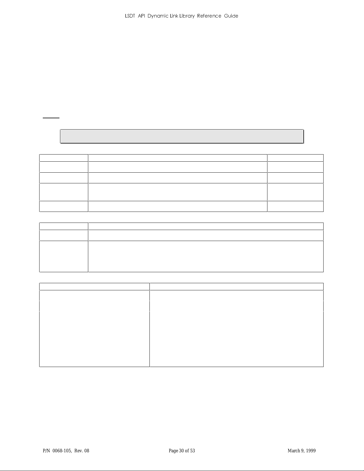
5.26 LS_MapImageData
Commands the driver to sel ect the ima g e memory page s p ecified by the ima g eO ffs et given. It is up to th e
application to read the image data from memory.
All the image data is accessed through a 32KB memor y mapped window in the Memory Address Space of th e ISA
BUS. By factory default, the DCB is set up so that this window is at 0xD0000. It ma y be changed during
ins tall ation. Da ta is al ways ma pped on a 32KB boundary. To a c ce s s a 10-MB im age containe d on thi s board, the
application can read the data directly from th e board but only 32KB at a time. After each 32KB chunk of image is
read, the driver must be cal led to map to the next chunk of data. In the examp le file, LSE X P , the use of th es e calls
(LS_MapImageWindow and LS_MapImageData) is demonstrated. Th is usage is very similar to
LS_ReadImageToPoi nter.
NOTE: Wh en u s in g the SCSI interfa ce, the memory mappin g mechani sm is “fa ked”. Sin ce the DCB i s inside th e
digit izer, th e op er ating system has n o direct acces s to the DC B im ag e memory.
SHORT LS_M apImageData (ReadStruct FAR *m ap ImagePar am);
Input Description Values
mapImageParam Pointer to Rea d Struct
- see LS_DT.H
->imageOffs et Offset from beginning of image data to set image memory map page.
->readSize Number of bytes application wishes to map. Should be 32,768 (one full
- see LS_DT.H
- see LS_DT.H
memory page).
->buffer[1] Unused for this function.
- see LS_DT.H
Output Description
mapImageParam Pointer to Rea d Struct
->bytesRead Number of bytes that application can access. If less than one full memory page, then
application should continue sending LS_MapImageData commands until either 1) Full
memor y pa g e is available for a ccess , 2) End Of Image status recei ved, or 3) Error or Scan
Abort ed s tatus recei ved. Applicati on can th en directly access image mem ory data safely.
Return Values Description
SUCCESS
HARDWARE_FAILURE
NOT_ENOUGH_DATA
Updated image data requested is available in Image Memory
Digitizer hardware malfunction
Number of bytes available is smaller than the number of bytes to read
– the available bytes will be read and that number of byt es will be
stored in ->bytesR ead. Mor e s can d ata is expect ed
END_OF_IMAGE
End of Image Reached; data is still available if ->bytesRead > 0
SCAN_ABORTED
HARDWARE_BUSY
P/N 0068-105, Rev. 08 Page 30 of 53 March 9, 1999
Scan aborted
Not in ri gh t scan state for thi s com mand
Page 33
/6'7$3,'\QDPLF/LQN/LEUDU\5HIHUHQFH*XLGH
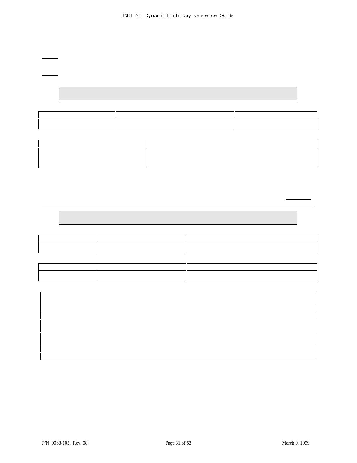
5.27 LS_MapImageWindow
Maps the DCB memory window into the program address space. Returns pointer to DCB Memory window.
NOTE: Windows has a limited number of resources to map memory. Be sure to call LS_UnMapImageWindow
when not scanning.
NOTE: Wh en u s in g the SCSI interfa ce, the memory mappin g mechani sm is “fa ked”. Sin ce the DCB i s inside th e
digit izer, th e op er ating system has n o direct acces s to the DC B im ag e memory.
SHORT LS_MapImageWindow (VOID FAR * FAR *imageWi ndowPtr);
Input Description Values
imageWindowPtr Pointer to the 32KB DCB Memory window virtual memory address
Return Values Description
SUCCESS
Function successful
DRIVER_NOT_INSTALL ED
The digitizer driver is not installed
5.28 LS_ModelNameString
Returns the model name string associ at ed with the input DACBModel model value. For example, an input value of
75 might be r eturned as “LS-75”. You can obtain the model ID from LS_GetStatus or LS_GetDrvInfo. Be sure to
supply an 80-character output buffer to recei ve the maximum stri ng , i ncl uding t er mina ting NULL character.
VOID LS_ModelNameString (SHORT DACBModel, CHAR FAR *strBuf);
Input Description Values
DACBModel Model ID number e.g. 20, 50, 75, 76, 85, 86, 135
Output Values Description
strBuf NULL terminated character string ASCII text description of digitizer model
DriverStruct ds;
CHAR szMessage[80]
if (LS_GetStatus(&ds) == SUCCESS)
{
LS_ModelNameString(ds.DACQModelRev.DACBModel, szMessage);
printf(“Digitizer Model: %s\n”, szMessage);
}
P/N 0068-105, Rev. 08 Page 31 of 53 March 9, 1999
Page 34
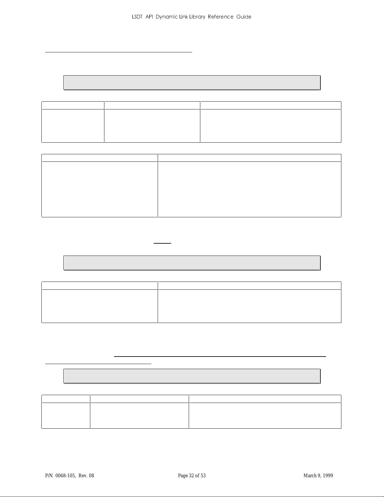
/6'7$3,'\QDPLF/LQN/LEUDU\5HIHUHQFH*XLGH
5.29 LS_Motor
NOT RECOMMENDED – DIAGNOSTIC USE ONLY
Star ts the film transport motor in the specifi ed d irection at the la s t motor speed or stops the motor. Use this
generalized function rather than LS_StartMotor() and LS_StopMotor()
SHORT LS_M otor (SHO RT motorCmd);
Input Description Values
motorCmd Motor command code
Return Values Description
SUCCESS
Function successful
FORWARD_MOTOR_DIRECTION
REVERSE_MOTOR_DIRECTION
STOP_MOTOR_DIRECTION
HARDWARE_BUSY
INVALID_PARAMETER
HARDWARE_FAILURE
DRIVER_NOT_INSTALL ED
LSDT not in IDLE state
In valid para meter
H/W failure – check p ower!
The digitizer driver is not installed
5.30 LS_OpenDevice
Creates a handle to the LSDT driver. This MUST be the first call to the LSDT API functions. This is a Win32
fu nction; it has no effect in Win16 systems but can be included for compatibility (it always returns SUCCESS).
SHORT LS_OpenDevice (VOID);
Return Values Description
SUCCESS
DRIVER_NOT_INSTALL ED
DEVICE_ALREADY_OPEN
Function successful
The digitizer driver is not installed
Digitizer in use
5.31 LS_PixelDepthString
Returns the pixel depth string associated with the input pi xelDepth code value. You can obtain the current pixel
depth from LS_GetStatus. Be sure to supply an 80-character output buffer to receive the maximum string,
including terminating NULL character.
VOID LS_PixelDepth String (SHORT pixelDepth, CHAR FAR *strBuf);
Input Description Values
PixelDepth 8-bit or 16-bi t pixel specifier code
P/N 0068-105, Rev. 08 Page 32 of 53 March 9, 1999
SCAN_8BITS or SCAN_12BITS
the pixelD epth value retur n ed by LS_G etStatus –
see LS_DT.H "Pixel Depth DEFINES"
Page 35
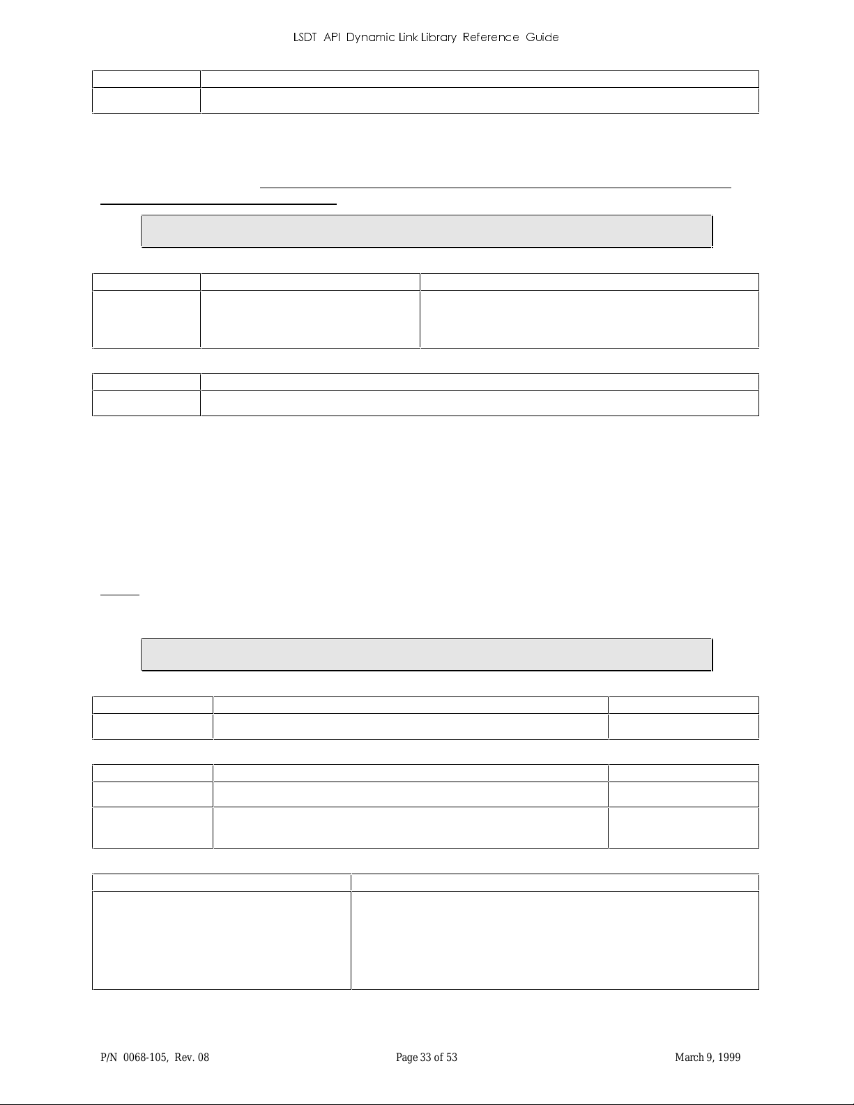
/6'7$3,'\QDPLF/LQN/LEUDU\5HIHUHQFH*XLGH
Outpu t Description
StrBuf ASCII string describing supplied pixel depth code copied into “strBuf” buff er
5.32 LS_PixelFormatString
Returns the pixel format string associated with the input pixelFormat code value. You can obtain the current pixel
format from LS_GetStatus. Be sure to supply an 80-character output buffer to receive the maximum string,
including terminating NULL character.
VOID LS_PixelFor matString (SHORT pixelFormat, CHAR FA R *strBuf);
Input Description Values
pixel F ormat Pixel format cod e
Output Description
strBuf ASCII string describing supplied pixel format is copied into “strBuf” buffer
MSB_FIRST or LSB_FIRST
the pixelFormat v alue returned by LS_GetStatus –
see LS_DT.H "Pixel Format DEFINES"
5.33 LS_ReadBarCode
Returns the current barcode data, and a valid / not valid status. This function is called with a pointer to a buffer to
receive t he barcod e d ata and a pointer to a len g th value. The length va lue defines the length of the user buffer on
input, and on output the actual length of the retur ned barcode data. The max i mum si ze of the barcode data is
“LS_BA RCO D E_MAX_S I ZE”, not includin g the terminatin g NULL chara cter (“0”) which i s a ppended to the
return data if the user buffer is large enough. If the buffer is not large enough the ter minating NULL will overwrite
barcode d ata (i.e. the retur ned data always ends with a NULL char acter.) The return s tatus is “1” for valid data, “0”
with a return length of zero if the data is not valid; all other values are LSDT error codes.
NOTE: Barcode data is valid from the time the barcode is read until the next scan is star ted (LS_StartFilmScan),
however the barcode data can NOT be read until the digitizer has st opped scanning. HARDWARE_BUSY
is ret urned if th e digitiz er is busy. The dat a can be read during the fi lm eject ph ase.
SHORT LS_ReadBarC ode (CHAR FAR *bar String, SHORT FAR *barStringSize);
Input Description Values
BarStringS ize Address of siz e of barStr ing
Output Description Values
BarStringS ize Cont ains leng th of t he barString not cou n ting the final 0 terminat or
BarString Loca tion to st ore barcode data stri ng
sizeof(ba rSt ring);
strlen(ba rSt ring);
NULL terminated
string
Return Values Description
0
1
HARDWARE_BUSY
other values
P/N 0068-105, Rev. 08 Page 33 of 53 March 9, 1999
Valid barcode data
Barcode d ata NOT valid
Digitizer is still scanning, tr y again later
ERROR!
Page 36
/6'7$3,'\QDPLF/LQN/LEUDU\5HIHUHQFH*XLGH
5.34 LS_ReadCalibrationTable
NOT RECOMMENDED – SUPERSEDED by LS_ReadLut
SHORT LS_ReadCalibrationTable (SHORT FAR *calibrationTable);
Output Description Values
calibrationTable Location to store DACQ Calibration Table values
Return Values Description
SUCCESS
Function successful
HARDWARE_BUSY
HARDWARE_FAILURE
DRIVER_NOT_INSTALL ED
LSDT not in IDLE state
H/W failure – check p ower!
The digitizer driver is not installed
5.35 LS_ReadCorrectionLookUpTable
NOT RECOMMENDED – SUPERSEDED by LS_ReadLut
SHORT LS_Read Correction LookUpTable (SH O RT FAR *LUT);
Output Description Values
LUT Location to stor e DACQ Corr ection LUT values
Return Values Description
SUCCESS
HARDWARE_BUSY
HARDWARE_FAILURE
DRIVER_NOT_INSTALL ED
Function successful
LSDT not in IDLE state
H/W failure – check p ower!
The digitizer driver is not installed
5.36 LS_ReadDiagnostic
NOT RECOMMENDED – DIAGNOSTIC USE ONLY
This function is very similar to the LS_ReadImageToPointer function. The principle difference is that the
LS_ReadDiagnostic function reads memory even if there is no image data present.
SHORT LS_Rea dDiagnostic (ReadStructPtr FAR *diagReadParamPtr);
Output Description
diagReadParamPtr Read Ptr Structure (see LS_DT. H)
P/N 0068-105, Rev. 08 Page 34 of 53 March 9, 1999
Page 37
SUCCESS
/6'7$3,'\QDPLF/LQN/LEUDU\5HIHUHQFH*XLGH
Return Values Description
Function su ccessfully read image data
INVALID_PARAMETER
HARDWARE_FAILURE
SCAN_ABORTED_ERROR
HARDWARE_BUSY
In valid para meter
H/W failure – check p ower!
Abort bu t ton pressed
This is returned when th e digitizer is in a transitor y state between the
star t of a s can and th e actual scan. Try again!
DRIVER_NOT_INSTALL ED
The digitizer driver is not installed
5.37 LS_ReadImageIntoBuffer
NOT RECOMMENDED – OBSOLETE
Commands the driver to r ead (copy) image data from the DCB memory into buffer memory on the host. This
function is called once a scan starts. Typically, this function is called in a loop with readSize = 32K until an
END_OF_IMAGE stat u s is received.
This function uses an obsolete input parameter structure that defines parameter values in the same memory block as
the ret ur ned scan da ta. Instea d, you should u s e LS _ Rea dIma g eToPointer functi on with it s “ReadStr u ctPtr” s tr u ct.
SHORT LS_Rea dIma geIntoBuffer (ReadStruct FAR *readParam);
Input Description Values
readParam Rea d S t ructure (see LS_DT.H) a byte count (readSize) of 32,768 is recommended
Return Values Description
SUCCESS
INVALID_PARAMETER
NOT_ENOUGH_DATA
END_OF_IMAGE
HARDWARE_FAILURE
SCAN_ABORTED_ERROR
HARDWARE_BUSY
DRIVER_NOT_INSTALL ED
DATA_LOST
Function su ccessfully read image data
In valid para meter
Number of bytes available is smaller than the number of bytes to read
– the available bytes will be read and that number of byt es will be
stored in ->bytesR ead. Mor e s can d ata is expect ed
Same as NOT_ENOUGH_DATA except the digit izer has finished
scanning the image
H/W failure – check p ower!
Abort bu t ton pressed
This is returned when th e digitizer is in a transitor y state between the
star t of a s can and th e actual scan. Try again!
The digitizer driver is not installed
Either the ima g e is larger than DCB memory or a data over run err or
has occur red
P/N 0068-105, Rev. 08 Page 35 of 53 March 9, 1999
Page 38
/6'7$3,'\QDPLF/LQN/LEUDU\5HIHUHQFH*XLGH
5.38 LS_ReadImageIntoFile
NOT RECOMMENDED – OBSOLETE
Causes the driver to read (copy) an entire image from the DCB memory into a file on the h ost. As the data becomes
available from the DCB, it is written into a host file. This file is in Lumisys image for mat (see Appendix A).
NOTE: It will ignore the Windows message queue for however long it takes to write the file (which is why this is
not recommen ded). It calls LS_ReadImageToPointer().
SHORT LS_ReadImageIntoFile (CHAR FAR *fileName );
Input Description Values
fileName path \ filename Any valid DOS path \ filename, e.g. XRAY1.IMG or
C:\USERS\JACK\XRAY1.IMG
Return Values Description
SUCCESS
Function successfully read image in to file
FILE_OPEN_ERROR
FILE_WRITE_ERROR
HARDWARE_FAILURE
SCAN_ABORTED_ERROR
MEMORY_ALLOCATION_FAILURE
DRIVER_NOT_INSTALLED
DATA_LOST
Could n ot open file
Could n ot write an y or all bytes to file
H/W failure – check p ower!
Abort bu t ton pressed
Could no t allocate enough memory
The digitizer driver is not installed
Either the ima g e is larger than DCB memory or a data over run err or
has occur red
5.39 LS_ReadImageIntoFile_Fast
NOT RECOMMENDED – OBSOLETE
This function is the same as th e LS_ReadImageIntoFile function, except implemented using the DCB mappin g
function s of the driver to read the incoming image directly from DCB memory. In the Win32 version of the library,
this function is exactly the same as LS_ReadImageIntoFile().
SHORT LS_ReadImageIntoFile_Fast (CHAR FA R *fileName );
Input Description Values
FileName path \ filename
Any valid DOS path/filename, e.g. XRAY1.IMG or
C:\USERS\JACK\XRAY1.IMG
P/N 0068-105, Rev. 08 Page 36 of 53 March 9, 1999
Page 39
SUCCESS
/6'7$3,'\QDPLF/LQN/LEUDU\5HIHUHQFH*XLGH
Return Values Description
Function successfully read image in to file
FILE_OPEN_ERROR
FILE_WRITE_ERROR
HARDWARE_FAILURE
SCAN_ABORTED_ERROR
MEMORY_ALLOCATION_FAILURE
DRIVER_NOT_INSTALLED
DATA_LOST
Could n ot open file
Could n ot write an y or all bytes to file
H/W failure – check p ower!
Abort bu t ton pressed
Could no t allocate enough memory
The digitizer driver is not installed
Either the ima g e is larger than DCB memory or a data over run err or
has occur red
5.40 LS_ReadImageToPointer
Commands the driver to r ead (copy) image data from the DCB memory into buffer memory on the host. This
function may be called when a scan is occurring. An application will typically call this function in a loop with
->readSize = 32K until an END_OF_IMAGE status is received. This function differs from
LS_Read Imag eIn toBuffer in that a field of the Rea d S tructP tr structure cont ains a FAR pointer specifyin g where to
store the imag e da ta – as opposed t o t he buffer s tarting in the Read Struct structur e itself.
SHORT LS_Rea dIma geToPointer (ReadStructPtr FAR *readParam);
Input Description Values
readParam Read P tr Structure (see LS _ D T.H) a byte coun t (readSi ze) of 32, 768 is r ecom mend ed
Return Values Description
SUCCESS
INVALID_PARAMETER
NOT_ENOUGH_DATA
END_OF_IMAGE
HARDWARE_FAILURE
SCAN_ABORTED_ERROR
HARDWARE_BUSY
DRIVER_NOT_INSTALL ED
DATA_LOST
Function su ccessfully read image data
In valid para meter
Number of bytes available is smaller than the number of bytes to read
– the available bytes will be read and that number of byt es will be
stored in ->bytesR ead. Mor e s can d ata is expect ed
Same as NOT_ENOUGH_DATA excep t the dig itizer ha s finished
scanning the image
H/W failure – check p ower!
Abort bu t ton pressed
This is returned when th e digitizer is in a transitor y state between the
star t of a s can and th e actual scan. Try again!
The digitizer driver is not installed
Either the ima g e is larger than DCB memory or a data over run err or
has occur red
5.41 LS_ReadLookUpTable
NOT RECOMMENDED – SUPERSEDED by LS_ReadLut
SHORT LS_Rea dLookUpTable (SHORT FAR *LUT);
P/N 0068-105, Rev. 08 Page 37 of 53 March 9, 1999
Page 40
/6'7$3,'\QDPLF/LQN/LEUDU\5HIHUHQFH*XLGH
Outpu t Descriptio n Values
LUT Location to store DACQ ULUT values
Return Values Description
SUCCESS
Function successful
HARDWARE_BUSY
HARDWARE_FAILURE
DRIVER_NOT_INSTALL ED
LSDT not in IDLE state
H/W failure – check p ower!
The digitizer driver is not installed
5.42 LS_ReadLut
Reads the specifi ed LUT from the DACQ into a user -supplied buffer. The caller needs to be sure to supply a large
enough buffer (up to 10,240 bytes). The data format of each entry is LSB fir st. This is a generalized version of
older, specific and now obsolete LUT functions: LS_ReadCalibrationTable, LS_ReadCorrectionLookUpTable, an d
LS_ReadLookUpTable.
NOTE: This function can only be done when the digitizer is IDLE.
UNIVERSAL_CAL_LUT_NUMBER
LS_ReadLut reads th e Calibration Lookup Table (Cal LUT) currently stored in the DACQ. Each entry in the table
is an un si gned 16-bi t integer . Th e nu mber of entr ies in the ta ble is equa l to the num ber of pixels p er line. The cal ler
needs to be sure to supply a large enough buffer, 2 bytes for each pixel for the digitizer’s maximum line size.
UNIVERSAL_CORR_LUT_ NUMBER
LS_ReadLut reads th e 4096 2-byte entries from the Correction Lookup Table (CLUT) curr ently stored in the
DACQ.
UNIVERSAL_USER_LUT_NUMBER
LS_ReadLut reads th e 4096 2-byte entries from the user Lookup Table (ULUT ) curr ently stored in the DACQ. The
User LUT on the DACQ contains 4096 16-bi t entries, into which the DACQ indexes with the 12-bit (0..4095)
optical den s i ty value for each pix e l scan ned.
SHORT LS_Rea dLut (USHORT LutNumber, SHORT FAR *LUT);
Input Description Values
LutNumber LUT ID number
Output Description Values
LUT Location to store DACQ LUT values
Return Values Description
SUCCESS
HARDWARE_BUSY
HARDWARE_FAILURE
DRIVER_NOT_INSTALL ED
Function successful
LSDT not in IDLE state
H/W failure – check p ower!
The digitizer driver is not installed
UNIVERSAL_CAL_LUT_NUMBER
UNIVERSAL_CORR_LUT _NUMBER
UNIVERSAL_USER_LUT_NUMBER
P/N 0068-105, Rev. 08 Page 38 of 53 March 9, 1999
Page 41
/6'7$3,'\QDPLF/LQN/LEUDU\5HIHUHQFH*XLGH
5.43 LS_RegisterCmd
NOT RECOMMENDED – DIAGNOSTIC USE ONLY
Reads or writes directly to the digitizer hardware registers.
SHORT LS_Regi sterCmd (RegDataCmdStruct FAR *RegDataCmd);
Input / Output Description
RegDataCmd See LS_DT.H
Return Values Description
SUCCESS
Function successful
HARDWARE_FAILURE
DRIVER_NOT_INSTALL ED
H/W failure – check p ower!
The digitizer driver is not installed
5.44 LS_ResetDriverVariables
NOT RECOMMENDED – DIAGNOSTIC USE ONLY
Resets the digitizer driver scanning par ameters to their initial settings used to detect cylinder width. This fun ction is
typicall y only used in diagnostics.
SHORT LS_ResetDriverVariables (VOID);
Return Values Description
SUCCESS
HARDWARE_FAILURE
DRIVER_NOT_INSTALL ED
Function successful
H/W failure – check p ower!
The digitizer driver is not installed
5.45 LS_ResetHardware
Resets the LSDT DACQ hardwar e and rein itializes th e LSDT digitizer driver. This function is a superset of th e
LS_ResetScan function. The digitizer LUTs are reset to th eir initial state at the time the driver was loaded in
addit ion to the LS_ ResetSca n op erati ons (see LS_Res etScan).
SHORT LS_ResetHardware (VOID);
Return Values Description
SUCCESS
HARDWARE_FAILURE
DRIVER_NOT_INSTALL ED
P/N 0068-105, Rev. 08 Page 39 of 53 March 9, 1999
Function successful
H/W failure – check p ower!
The digitizer driver is not installed
Page 42
/6'7$3,'\QDPLF/LQN/LEUDU\5HIHUHQFH*XLGH
5.46 LS_ResetScan
Reinitializes the LSDT digitizer driver. It does NOT reset the DACQ hardware (th e DACQ retains its current
Lookup and Calibration Tables). Stops the current scan if one is in progress. The LS_ResetScan functionality is
automatically performed at the end of all normal scans, when a start scannin g (LS_StartFilmScan) fails due to bad
param eters, and when the ed g es of the film can not be foun d d ur ing a scan operation.
NOTE: The film is not ejected.
SHORT LS_ResetScan (VOID) ;
Return Values Description
SUCCESS
Function successful
HARDWARE_FAILURE
DRIVER_NOT_INSTALL ED
H/W failure – check p ower!
The digitizer driver is not installed
5.47 LS_ScanModeString
Returns the scan mode str ing associ ated with the input scanMode cod e va lue. You can obt ain th e scan mode from
LS_GetStatus. Be sure to supply an 80-character output buffer to receive the maximum string, including
terminating NULL character.
VOID LS_ScanModeStrin g (SHORT scan Mode, C HAR FAR *strBuf);
Input Description Values
scanMode Sca n m ode value code
Output Description
strBuf Pointer to ASCII string describing supplied scan mode – "Variable resolution" or " Fixed
resolution"
scanMode value returned by LS_GetStatus – see
LS_DT.H "Scan Mode DEFIN ES"
5.48 LS_SetAveragingMode
Dir ects the digitizer driver t o us e th e s p ecified pixel averagin g m ode (see secti on 2.2.4) during the next sca n only,
regular or diagnostic.
SHORT LS_S etAver agingMode (SHORT averagingMode) ;
Input Description Values
averagingMode Specifies pixel averaging mode
Return Values Description
SUCCESS
ILLEGAL_AVG_MODE
P/N 0068-105, Rev. 08 Page 40 of 53 March 9, 1999
Function successful
Illegal averaging mode
NO_AVERAGING
X_ONLY_AVERAGING
X_AND_Y_AVERAGING
Page 43
/6'7$3,'\QDPLF/LQN/LEUDU\5HIHUHQFH*XLGH
5.49 LS_SetDevNum
Allows you to select a particular DCB if you have more than one installed. Only useful for Win16.
SHORT LS_SetDevNum (USHO RT targetDevNum);
Input Description Values
targetDevNu m Which board 1, 2, 3, …
Return Values Description
SUCCESS
Function successful
HARDWARE_FAILURE
DRIVER_NOT_INSTALL ED
H/W failure – check p ower!
The digitizer driver is not installed
5.50 LS_SetLaserMode
NOT RECOMMENDED – DIAGNOSTIC USE ONLY
Dir ects the DACQ t o set the scanning la s er (or CCD illu minati on sub-system ) to the sp ecified mod e.
SHORT LS_S etLaserMode (S HO RT laserM od e) ;
Input Description Values
laserMode Specifies laser mode
Return Values Description
SUCCESS
HARDWARE_FAILURE
Function successful
H/W failure – check p ower!
LASER_OFF
LASER_IDLE
LASER_ON
5.51 LS_SetNextScanParams
NOT RECOMMENDED – DIAGNOSTIC USE ONLY
Sets special parameters for the next film scan or Mode 5 Diagnostic Scan. All values are reset to their default values
after the next scan completes. This function ONLY affects the next scan.
SHORT LS_S etNextScanParams ( S etNextScanFilmS truct FAR *N ex tScanParams ) ;
P/N 0068-105, Rev. 08 Page 41 of 53 March 9, 1999
Page 44
/6'7$3,'\QDPLF/LQN/LEUDU\5HIHUHQFH*XLGH
Input Descrip tion Values
NextScan Params Pointer to a Parameter Block
->ParamType Param eter type
->ParamValue Value to set
Return Values Description
SUCCESS
HARDWARE_FAILURE
Function successful
H/W failure – check p ower!
NEXT_SCAN_TYPE_PMT_VOLT
NEXT_SCAN_TYPE_AUTOZERO
NEXT_SCAN_TYPE_ENDSCAN
NEXT_SCAN_TYPE_LASER
NEXT_SCAN_TYPE_SDR
NEXT_SCAN_TYPE_NOEDGE
NEXT_SCAN_TYPE_AVG_MODE
5.52 LS_SetPMTvoltage
Allows you to adjust the PMT high-voltage bias. This function ONLY affects th e next scan. CR digitizer s only.
SHORT LS_SetPMTvoltage (UCHAR PMTadjust);
Input Description Values
PMTadjust How much to a djust PMT voltage
Return Values Description
SUCCESS
HARDWARE_FAILURE
Function successful
H/W failure – check p ower!
all values from 0 to 255, i nclusive:
0 max Neg. voltage (less gain)
128 0V (nominal or default gai n)
255 max Pos. voltage (more gai n)
5.53 LS_SetSDRMode
Enables the Shifted Dynamic Range (SDR) mode for the next scan. After the next scan, the mode is automatically
disabled. This is only used with an LS85 with the SDR option.
SHORT LS_SetSDRMode (int SdrMode);
Input Description Values
SdrMode Turn SDR mode O N or OF F
SDR_MODE_ENABLE
SDR_MODE_DISABLE
P/N 0068-105, Rev. 08 Page 42 of 53 March 9, 1999
Page 45
SUCCESS
/6'7$3,'\QDPLF/LQN/LEUDU\5HIHUHQFH*XLGH
Return Values Description
Function successful
HARDWARE_FAILURE
H/W failure – check p ower!
5.54 LS_SetTrim
Adds or subtracts pixels from where the film edges are detected. Its primary purpose is to a ccount for the rounded
corn er s on scan ned media. You can al s o trim a bit ex tr a to insure that no “air ” is included on the image edges . This
funct ion ONLY affe cts the n ext scan.
SHORT LS_S etTr im (SHORT leftTrim, SHORT ri ghtTrim );
Input Description
leftTrim Number of mils (.001”) to trim from (if positive) or add to (if negative) left edge of film
rightTrim Number of mils (.001”) to trim from (if positive) or add to (if negative) right edge of film
Return Values Description
SUCCESS
HARDWARE_BUSY
HARDWARE_FAILURE
DRIVER_NOT_INSTALL ED
Function successful
LSDT not in IDLE state
H/W failure – check p ower!
The digitizer driver is not installed
5.55 LS_StartFilmScan
Commands the dr iver to start scann in g a film.
SHORT LS_StartFilmScan (SHORT pixelResolution, SHORT scanResMode,
SHORT pixelDepth, SHORT pixelFormat);
Input Description Values
pixelResolution Pixels per line (scanMode = VARIABLE)
Pixels per inch (scanMode = FIXED)
scanResMode FIXED or VARIABLE mode
pixelDepth 8 or 12 bit s per pixel
pixelFormat MSB or LSB first
256 ... 5120 – depends on digitizer model
36 ... 730 – depends on digitizer model
FIXED_RESOLUTION
VARIABLE_RESOLUTION
SCAN_8BITS
SCAN_12BITS
MSB_FIRST
LSB_FIRST (normal PC setting)
P/N 0068-105, Rev. 08 Page 43 of 53 March 9, 1999
Page 46
SUCCESS
/6'7$3,'\QDPLF/LQN/LEUDU\5HIHUHQFH*XLGH
Return Values Description
Function successful
PIXELS_PER_LINE_OUT_OF_RANGE
ILLEGAL_SCAN_MODE
ILLEGAL_BITS_PER_PIXEL
ILLEGAL_PIXEL_FORMAT
HARDWARE_BUSY
HARDWARE_FAILURE
SCAN_ABORTED_ERROR
DRIVER_NOT_INSTALL ED
In valid para meter
In valid para meter
In valid para meter
In valid para meter
LSDT not in IDLE state
H/W failure – check p ower!
Abort bu t ton pressed
The digitizer driver is not installed
5.56 LS_StartFilmScanNoCLUT
NOT RECOMMENDED – DIAGNOSTIC USE ONLY
Commands the driver to start scanning a film. This function differs from the LS_StartFilmScan function because
the pi xel data bypasses the “CLUT” hardware. The CLUT corr ects the pi xel data value to the true opti cal densi ty.
LS_StartFilmScanNoCLUT is only used by diagnostic pr ograms.
SHORT LS_StartFilmScanNoCLUT (SHORT pixelResolution , SHORT
scanResMode,
SHORT pixelDepth, SHORT
pixelFormat);
Input Description Values
pixelResolution Pixels per line (scanMode = VARIABLE)
Pixels per inch (scanMode = FIXED)
scanResMode FIXED or VARIABLE mode
pixelDepth 8 or 12 bits per pixel
pixelFormat MSB or LSB first
Return Values Description
SUCCESS
PIXELS_PER_LINE_OUT_OF_RANGE
ILLEGAL_SCAN_MODE
ILLEGAL_BITS_PER_PIXEL
ILLEGAL_PIXEL_FORMAT
HARDWARE_BUSY
HARDWARE_FAILURE
Function successful
In valid para meter
In valid para meter
In valid para meter
In valid para meter
LSDT not in IDLE state
H/W failure – check p ower!
256 ... 5120 -- depends on digitizer model
36 ... 730 -- depends on digitizer model
FIXED_RESOLUTION
VARIABLE_RESOLUTION
SCAN_8BITS
SCAN_12BITS
MSB_FIRST
LSB_FIRST (normal PC setting)
SCAN_ABORTED_ERROR
DRIVER_NOT_INSTALL ED
P/N 0068-105, Rev. 08 Page 44 of 53 March 9, 1999
Abort bu t ton pressed
The digitizer driver is not installed
Page 47
/6'7$3,'\QDPLF/LQN/LEUDU\5HIHUHQFH*XLGH
5.57 LS_StartMotor
NOT RECOMMENDED – DIAGNOSTIC USE ONLY – SUPERSEDED by LS_Motor
Star ts the film transport motor in th e s p ecified directi on at the last specified motor s p eed .
SHORT LS_StartMotor (SHORT dir ection);
Input Description Values
Direction Direction to start motor
Return Values Description
SUCCESS
Function successful
FORWARD_MOTOR_DIRECTION
REVERSE_MOTOR_DIRECTION
HARDWARE_BUSY
INVALID_PARAMETER
HARDWARE_FAILURE
DRIVER_NOT_INSTALL ED
LSDT not in IDLE state
In valid para meter
H/W failure – check p ower!
The digitizer driver is not installed
5.58 LS_StatusOfLastScanString
Returns the status of last scan string associated with the input statusOfLastScan code value. You can obtain the
status of last scan from LS_GetStatus. Be sure to supply an 80-char acter output buffer to recei ve the maximum
string, including terminating NULL character.
VOID LS_StatusOfLastScanString (SHORT statusOfLastScan, CHAR FAR *strBuf);
Input Description Values
statusOfLastScan Status code value
Output Description
strBuf Poi nter to ASCII string describing supplied status code is copied into “strBuf” buffer
statusOfLastScan value returned by LS_GetStatus function –
see LS_DT.H "Status of Last Scan DEFINES"
5.59 LS_StopMotor
NOT RECOMMENDED – DIAGNOSTIC USE ONLY – SUPERSEDED by LS_Motor
Stops the film tran sport motor in the LSDT.
SHORT LS_StopMotor (VOID) ;
Return Values Description
SUCCESS
HARDWARE_BUSY
HARDWARE_FAILURE
DRIVER_NOT_INSTALL ED
P/N 0068-105, Rev. 08 Page 45 of 53 March 9, 1999
Function successful
LSDT not in IDLE state
H/W failure – check p ower!
The digitizer driver is not installed
Page 48
/6'7$3,'\QDPLF/LQN/LEUDU\5HIHUHQFH*XLGH
5.60 LS_StopScanEject
Stops the current film s can and ejects the film.
SHORT LS_StopScanEject (VOID);
Return Values Description
SUCCESS
Function successful
HARDWARE_FAILURE
DRIVER_NOT_INSTALL ED
H/W failure – check p ower!
The digitizer driver is not installed
5.61 LS_UnMapImageWindow
Removes t he DCB Mem or y window from the user’ s ad dress space. See LS_Ma p ImageWindow.
NOTE: Windows has a limited number of resources to map memory. Be sure to call LS_UnMapImageWindow
when not scanning.
NOTE: When usin g th e S C S I interfa ce, the memory mappin g mechanism is “faked ”. Since the DCB is in si d e the
digit izer, th e op er ating system has n o direct acces s to the DC B im ag e memory.
SHORT LS_UnMapImageWind ow (VOID);
Return Values Description
SUCCESS
DRIVER_NOT_INSTALL ED
Function successfully freed address space
The digitizer driver is not installed
5.62 LS_WriteMemory
NOT RECOMMENDED
Writes data into th e DCB image memory. This function is used to perform memory tests. This function is ONLY
available in the Win32 version of the library.
SHORT LS_WriteMemory (WriteParamStruct *wr iteImageParamPtr);
Input Description
writ eI magePar amPtr see LS_ DT.H
Return Values Description
SUCCESS
P/N 0068-105, Rev. 08 Page 46 of 53 March 9, 1999
Function successful
Page 49
/6'7$3,'\QDPLF/LQN/LEUDU\5HIHUHQFH*XLGH
BBBBB BBBB BB BBB BBBB BB BB BBBBB BB BB BBBB BB BBB BBBB BB BB BBBB BBB BB BBBB BB BB BB
$SSHQGL[$
/ 80,6<6,0$*(+($'(5)250$7
BBBBBBBBBBBBBBBBBBBBBBBBBBBBBBBBBBBBBBBBBBBBBBBBBBBBBBBBBBBBBBBBBBB
Byte Nr Max
Offset Type Description Bytes Bytes Example No t es
0 – 803 N/A Internal Use 804 * DO NOT USE! *
804 – 805 Integer Number of Images 21
806 – 807 Integer Pixels per Line 2 2048
808 – 809 Integer Lines per Image 2 2486
810 – 811 Integer Bits per P ix el 212
812 – 813 Integer Window 2 4095 0 or 65535 imply not used
814 – 815 Integer Level 2 2048 0 or 65535 imply not used
816 – 830 String Filename 15 14 “LSDT.IMG”
831 – 844 String Date 14 13 “08/12/99”
845 – 848 Long Tim e 4 875029872 DOS Time Format
(Seconds since 01/01/1970)
849 – 878 String Image Source 30 29 “img_devi ce" Wher e image ca me from.
Could be person, company, etc.
879 – 958 String Comment 8 0 79 “Fi ltered & enhanced”
959 – 989 String System Description 31 30 “LS75”
990 – 999 String Header ID 10 N/A “Lumisys” Header format authentication
(Exactly as shown!)
1000 – 1007 String Version ID 8 N/A “Hdr_Ver” Version authentication
(Exactly as shown!)
1008 – 1009 Integer Version Number 2 4 Signifies version 4
1010 – 1011 Integer Byte Order 2 0 0 = LSB, 1 = MSB, 2 = ?SB
1012 – 2047 N/A Internal Use 1036 * DO NOT USE! *
___________________________________________________________________
These values are accessi ble in the include files LS_HDR.H and LS_HDROB. H. The latter is more object oriented and
can be used with LS_HDROB.C. Support for images is supplied in LS_IMG.H and LS_IMG.C.
All h ead er data is st ored LSB firs t; the “Byte Order” fi eld only pertain s to the image da ta which foll o ws.
“Max Bytes” mean s how many bytes you can put into this string field, not counting the terminating NULL character.
Be sure to te rminate all s tri ngs with a 0.
In general, for pre-existing headers, you should only change the bold-faced items above (“Number of Images” to
“System Description”).
If “Hdr_Ver” is not found at 1000, then the Version Number at 1008 is undefined.
If creating a header from scratch, the Header ID, Version ID and Version Number are required, in addition to reasonable
values of all the b old-faced items.
Version 3 Added Version ID and Version Number
Version 4 Added By te Order
_____ __ ____ ___ __ __ __ ____ ___ __ __ __ ____ ___ __ __ __ __ ____ ___ __ __ __ ____ __
P/N 0068-105, Rev. 08 Page 47 of 53 March 9, 1999
Page 50
/6'7$3,'\QDPLF/LQN/LEUDU\5HIHUHQFH*XLGH
BBBBB BBBB BB BBB BBBB BB BB BBBBB BB BB BBBB BB BBB BBBB BB BB BBBB BBB BB BBBB BB BB BB
$SSHQGL[%
)81&7,21(5525&2'(6
BBBBBBBBBBBBBBBBBBBBBBBBBBBBBBBBBBBBBBBBBBBBBBBBBBBBBBBBBBBBBBBBBBB
This section contains a complete list of possible decimal error codes returned by LSDT functions. The
corr espondin g #d efi nes ar e in LS_ D T.H. If th e mean ing below is bl ank, then that error code is n ot used.
Code Meaning Code Meaning Code Meaning
0 No error – su cces sful
1 Illegal parameter buffer size
2 Illegal driver fun ction code
3 Pixels per line out of r an ge
4 Illegal scan mode
5 Illegal bits per pixel
6 Illegal pixel format
7 Illegal bytes to read
8 Hardware bus y
9 Scan Timeout error
10
11 Not enough data
12 End of image
13
14 Calibration t able out of r ange
15
16
17
18
19
20
21 Hardware fai lure
22 Scan aborted error
23 CLUT file error
24 LUT file size error
25
26 Illegal averaging mode
27 Illegal Byt es To Write
28 Da t a Lost (a )
29 SDR shift error
30 Multiple File Match es
31 Bad File Pathname
32 Open File error
33 Read File err or
34 C lose File er ror
35 Illegal Parameter
36
37 Cylinder Edge Detect Threshold Error
38
39 Film Edge Detect Bad Offset
40 Film Edge Detect No Film
41
42 Film Edge Detect Bad Limits
43 Sp ecial F unction s Dis abled (b)
44 Film Edge Detect Bad Edges
(Edge detect failed)
45 Illegal Pixels Per Inch (c)
46 Fixed Resolution error (d)
47 Unkn own error
48 Memory Allocation error
49 Device Al ready Open
50 Driver Not In stalled
51 Map Window error
52 Win dow Not Mapped
53 Unmap Window error
54 DLL D river Rev Mismat ch
55 Unknown Debug Subcode
56 Win dow Already Mapped
57 I llegal Im age Offset
58 SCSI General error
59 SC S I D evi ce Not Present
60 SCSI LSDT Scanner Not Found
61 SCSI In q uir y Respon se Forma t In vali d
62 SCSI Sense error
63 SCSI Scanner Not Open
64 Fun ction Not Supported
65 File Open error
66 File Write error
67 File Cl ose er ror
68 File Read err or
69 File Size err or
70 File Di sk Sp ace err or
71 File Not Specified
72 End Of Fil e
73 Not Enough Disk Space
74 Invalid Filen ame
75 No Lumisys Image Header Found
(a) Either the image is lar g er th an the available m emory on the DCB or in the “wrapping ” mode the ap pl ication ha s
not taken the data fast enough to keep up with the incoming scan data. Pedal faster.
(b) Some functions can only be called in debug mode.
(c) For example, an LS-20 allows onl y 73 or 146 DPI
(d) You specified a value that will chop off or add more than 1”.
P/N 0068-105, Rev. 08 Page 48 of 53 March 9, 1999
Page 51
/6'7$3,'\QDPLF/LQN/LEUDU\5HIHUHQFH*XLGH
BBBBB BBBB BB BBB BBBB BB BB BBBBB BB BB BBBB BB BBB BBBB BB BB BBBB BBB BB BBBB BB BB
6&6,(5525&2'(6
BBBBBBBBBBBBBBBBBBBBBBBBBBBBBBBBBBBBBBBBBBBBBBBBBBBBBBBBBBBBBBBBB
This section contain s a complete list of possible hexadecimal error codes returned by LS_GetLastScsiError().
NOTE: Most of th ese error codes will not be returned by LSDT digitizer s.
SCSI Error Codes – Numerical Order
0x0000 SCSI_GOOD 0x0001 FILEMARK_DETECTED
0x0002 END_OF_PARTITION_MEDIUM_DETECTED 0x0003 SETMARK_DETECTED
0x0004 BEGINNING_OF_PARTITION_MEDIUM_DETECTED 0x0005 END_OF_DATA_DETECTED
0x0006 I_O_PROCESS_TERMINATED 0x0011 AUDIO_PLAY_OPERATION_IN_PROGRESS
0x0012 AUDIO_PLAY_OPERATION_PAUSED 0x0013 AUDIO_PLAY_OPERATION_SUCCESSFULLY_COMPLETED
0x0014 AUDIO_PLAY_OPERATION_STOPPED_DUE_TO_ERROR 0x0015 NO_CURRENT_AUDIO_STATUS_TO_RETURN
0x0100 NO_INDEX_SECTOR_SIGNAL 0x0200 NO_SEEK_COMPLETE
0x0300 PERIPHERAL_DEVICE_ WRITE_FAULT 0x0301 NO_WRITE_CURRENT
0x0302 EXCESSIVE_WRITE_ERRORS 0x0400 LOGICAL_UNIT_NOT_READY_CAUSE_NOT_REPORTABLE
0x0401 LOGICAL_UNIT_IS_IN_PROCESS_OF_BECOMING_READY 0x0402 LOGICAL_UNIT_NOT_READY_INITIALIZING_COMMAND_REQUIRED
0x0403 LOGICAL_UNIT_NOT_READY_MANUAL_INTERVENTION_REQUIRED 0x0404 LOGICAL_UNIT_NOT_READY_FORMA T_IN_PR OGRESS
0x0500 LOGICAL_UNIT_DOES_NOT_RESPOND_TO_SELECTION 0x0600 REFERENCE_POS ITION_FOUND
0x0700 MULTIPLE_PERIPHERAL_DEVICES_SELECTED 0x0800 LOGICAL_UNIT_COMMUNICATION_FAILURE
0x0801 LOGICAL_UNIT_COMMUNICATION_TIME_OUT 0x0802 LOGICAL_UNIT_COMMUNICATION_PARITY_ERROR
0x0900 TRACK_FOLLOWING_ERROR 0x0901 TRACKING_SERVO_FAIL URE
0x0902 FOC US_SERVO_FAILURE 0x0903 SPINDLE_SERVO_FAILURE
0x0A00 ERROR_LOG_OVERFLOW 0x0C00 WRITE_ERROR
0x0C01 WRITE_ERROR_RECOVERED_WITH_AUTO_REALLOCATION 0x0C02 WRITE_ERROR_AUTO_REALLOCATION_FAILED
0x1000 ID_CRC_OR_ECC_ERROR 0x1100 UNRECOVERED_READ_ERROR
0x1101 READ_ RETRIES_EXHAUSTED 0x1102 ERROR_TOO_LONG_TO_CORRECT
0x1103 MULTIPLE_READ_ERRORS 0x1104 UNRECOVERED_READ_ERROR_AUTO_REALLOCATE_FAILED
0x1105 L_EC_UNCORRECTABLE_ERROR 0x1106 CIRC_UNRECOVERED_ERROR
0x1107 DATA_RES YNCHRONIZATION_ERROR 0x1108 INCOMPLETE_BLOCK_ READ
0x1109 NO_ GAP_FOUND 0x110A MISCORRECTED_ERROR
0x110B UNRECOVERED_READ_ERROR_RECOMMEND_REASSIGNMENT 0x110C UNRECOVERED_READ_ERROR_RECOMMEND_REWRITE_THE_DATA
0x1200 ADDRESS_MARK_NOT_FOUND_FOR_ID_FIELD 0x1300 ADDRESS_MARK_NOT_FOUND_FOR_DATA_FIELD
0x1400 REC OR DED_ENTITY_NOT_FOUND 0x1401 RECORD_NOT_FOUND
0x1402 FILEMARK_OR _SETMARK_NOT_FOUND 0x1403 END_OF_DATA_NOT_FOUND
0x1404 BLOCK_SEQUENCE_ER ROR 0x1500 RANDOM_POSITIONING_ERROR
0x1501 MECHANICAL_P OSITIONING_ERROR 0x1502 POSITIONING_ERROR_DETECTED_BY_READ_OF_MEDIUM
0x1600 DATA_SYNCHRONIZATION_MARK_ERROR 0x1700 RECOVERED_DATA_WITH_NO_ERROR_CORRECTION_APPLIED
0x1701 RECOVERED_DATA_WITH_RETRIES 0x1702 RECOVERED_DATA_WITH_POSITIVE_HEAD_OFFSET
0x1703 RECOVERED_ DATA_WITH_NEGATIVE_HEAD_OFFSET 0x1704 RECOVERED_DATA_WITH_RETRIES_AND_OR_CIRC_APPLIED
0x1705 REC OVERED_DATA_USING_PREVIOUS_SECTOR_ID 0x1706 RECOVER ED_DATA_WITHOUT_ECC_DATA_AUTO_REALLOCATED
0x1707 REC OVERED_DATA_WITHOUT_ECC_RECOMMEND_REASSIGNMENT 0x1708 RECOVERED_DATA_WITHOUT_ECC_R EC OMMEND_REWRITE
0x1800 REC OVERED_DATA_WITH_ERROR_CORRECTION_APPLIED 0x1801 RECOVERED_ DATA_WITH_ERROR_CORRECTION_AND_RETRIES_APPLIED
0x1802 REC OVERED_DATA_DATA_AUTO_REALLOCATED 0x1803 RECOVERED_DATA_WITH_CIRC
0x1804 REC OVERED_DATA_WITH_LEC 0x1805 REC OVERED_DATA_RECOMMEND_REASSIGNMENT
0x1806 REC OVERED_DATA_RECOMMEND_REWRITE 0x1900 DEFECT_LIST_ERROR
0x1901 DEFECT_LIST_NOT_AVAILABLE 0x1902 DEFECT_LIST_ERROR_IN_PRIMARY_LIST
0x1903 DEFECT_LIST_ERROR_IN_GROWN_LIST 0x1A00 PARAMETER_LIST_LENGTH_ERROR
P/N 0068-105, Rev. 08 Page 49 of 53 March 9, 1999
Page 52
/6'7$3,'\QDPLF/LQN/LEUDU\5HIHUHQFH*XLGH
SCSI Error Codes – Numerical Order
0x1B00 SYNCHRONOUS_DATA_TRANSFER_ERROR 0x1C00 DEFECT_LIST_NOT_FOUND
0x1C01 PR IMARY_DEFECT_LIST_NOT_FOUND 0x1C02 GR OWN_DEFECT_LIST_NOT_FOUND
0x1D00 MISCOMPARE_DURING_VERIFY_OPERATION 0x1E00 RECOVERED_ID_WITH_ECC
0x2000 INVALID_COMMAND_OP ERATION_CODE 0x2100 LOGICAL_BLOCK_ADDRESS_OUT_OF_ R ANGE
0x2101 INVALID_ELEMEN T_ADDR ESS 0x2200 ILLEGAL_FUNC TION
0x2400 INVALID_FIELD_IN_CDB 0x2500 LOGICAL_UNIT_NO T_SUPPORTED
0x2600 INVALID_FIELD_IN_PARAMETER_LIST 0x2601 PARAMETER_NOT_SUPPORTED
0x2602 PARAMETER_VALUE_INVALID 0x2603 THRESHOLD_PARAMETERS_NOT_SUPPORTED
0x2700 WRITE_PROTECTED 0x2800 NOT_READY_TO_READY_TRANSITION
0x2801 IMPORT_OR_EXPOR T_ELEMEN T_ACC ESSED 0x2900 POW ER_ON_RESET_OR_BUS_DEVICE_RESET_OCCURRED
0x2A00 PARAMETERS_CHANGED 0x2A01 MODE_PARAMETERS_ CHANGED
0x2A02 LOG_PAR A METERS_CHANGED 0x2B00 COPY_CANNOT_EXECUTE_SINCE_HOST_CANNOT_DISCONNECT
0x2C00 C OMMAND_ SEQUENCE_ERROR 0x2C01 TOO_MANY_WINDOW S _SPECIFIED
0x2C02 INVALID_COMB INATION_OF_WINDOWS_SPECIFIED 0x2D00 OVERWRITE_ERROR_ON_UPDATE_IN_PLACE
0x2F00 COMMANDS_CLEARED_BY_ANOTHER_INITIATOR 0x3000 INCOMPATIBLE_MEDIUM_INSTALLED
0x3001 CANNOT_READ_MEDIUM_UNKNOWN_FORMAT 0x3002 CANNOT_READ_MEDIUM_INCOMPATIBLE_FORMAT
0x3003 CLEANING_CARTRIDGE_INSTALLED 0x3100 MEDIUM_FORMAT_CORRUPTED
0x3101 FOR MAT_COMMAND_FAILED 0x3200 NO_DEFECT_SPARE_ LOC ATION_AVAILABLE
0x3201 DEFECT_LIST_UPDATE_FAILURE 0x3300 TAPE_LENGTH_ERROR
0x3600 RIBBON_INK_OR_ TONER_FAILURE 0x3700 ROUNDED_PARAMETER
0x3900 SAVING_PARAMETERS_NOT_SUPPORTED 0x3A00 MEDIUM_NOT_PRESENT
0x3B00 SEQUENTIAL_POSITIONING_ERROR 0x3B01 TAPE_POSITION_ERROR_AT_BEGINNING_OF_MEDIUM
0x3B02 TAPE_POSITION_ERROR_AT_END_OF_MEDIUM 0x3B03 TAPE_OR_ELECTRONIC_VERTICAL_FORMS_UNIT_NOT_READY
0x3B04 SLEW_FAILURE 0x3B05 PAPER_JAM
0x3B06 FAILED_TO_SENSE_TOP_OF_FORM 0x 3B07 FAILED_TO_SENSE_BOTTOM_OF_FOR M
0x3B08 R EPOSITION_ERROR 0x3B09 READ_PAST_END_OF_MEDIUM
0x3B0A READ_ P AS T_BEGINNING_OF_ MEDI UM 0x3B0B POSITION_PAST_END_OF_MEDIUM
0x3B0C POSITION_PAST_BEGINNING_OF_MEDIUM 0x3B0D MEDIUM_DESTINATION_ELEMENT_FULL
0x3B0E MEDIUM_SOURCE_ELEMENT_EMPTY 0x3D00 INVALID_B ITS_IN_IDENTIFY_MESSAGE
0x3E00 LOGICAL_UNIT_HAS_NOT_SELF_CONFIGURED_YET 0x3F00 TARGET_OPERATING_CONDITIONS_HAVE_CHANGED
0x3F01 MICROCODE_HAS_BEEN_CHANGED 0x3F02 CHANGED_OPERATING_DEFINI TION
0x3F03 INQUIRY_DATA_HAS_CHANGED 0x4000 DIAGNOSTIC_FAILURE_ON_COMPONENT_NN
0x4000 RAM_FAILURE 0x4100 DATA_PATH_FAILURE
0x4200 POWER_ON_OR_SELF_TEST_FAILURE 0x4300 MESSAGE_ERROR
0x4400 INTERNAL_TARGET_FAILURE 0x4500 SELECT_OR_RESELECT_FAILURE
0x4600 UNSUCCESSFUL_SOFT_RESET 0x4700 SCSI_PARITY_ERROR
0x4800 INITIATOR_DETECTED_ERROR_MESSAGE_RECEIVED 0x4900 INVALID_MESSAGE_ERROR
0x4A00 COMMAND_PHASE_ERR OR 0x4B00 DATA_PHASE_ERR OR
0x4C00 LOGICAL_UNIT_FAILED_SELF_CONFIGURATION 0x4E00 OVERLAPPED_COMMANDS_ATTEMPTED
0x5000 WRITE_APPEND_ERROR 0x5001 WR ITE_APPEND_POSITION_ERROR
0x5002 POSITION_ERROR_RELATED_TO_TIMING 0x5100 ERASE_FAILURE
0x5200 CARTRIDGE_FAULT 0x5300 MEDIA_LOAD_OR_EJECT_FAILED
0x5301 UNLOAD_TAPE_ F AILURE 0x5302 MEDIUM_REMOVAL_PREVENTED
0x5400 SCSI_TO_HOST_SYSTEM_INTERFACE_FAILURE 0x5500 SYSTEM_RESOURCE_FAILURE
0x5700 UNABLE_TO_RECOVER_TABLE_OF_CONTENTS 0x5800 GENERA TION_DOES_NOT_EXIST
0x5900 UPDATED_BLOCK_R EAD 0x5A00 OPERATOR_REQUEST_OR_STATE_CHANGE_INPUT
0x5A01 OPERATOR_MEDIUM_REMOVAL_REQUEST 0x 5A02 OPERATOR_SELECTED_WRITE_PROTECT
0x5A03 OPERATOR_SELECTED_WRITE_PERMIT 0x5B00 LOG_EXCEPTION
0x5B01 THRESHOLD_ CONDITION_MET 0x5B02 LOG_COUNTER_AT_MAXIMUM
0x5B03 LOG_ LIST_CODES_EXHAUSTED 0x5C00 R PL_STATUS_CHANGE
P/N 0068-105, Rev. 08 Page 50 of 53 March 9, 1999
Page 53
/6'7$3,'\QDPLF/LQN/LEUDU\5HIHUHQFH*XLGH
SCSI Error Codes – Numerical Order
0x5C01 SPINDLES_SYNCHRONIZED 0x5C02 SPINDLES_NOT_SYNCHRONIZED
0x6000 LAMP_FAILURE 0x6100 VIDEO_ACQUISITION_ERROR
0x6101 UNABLE_TO_ACQUIRE_VIDEO 0x6102 OUT_OF_FOCUS
0x6200 SC AN_HEAD_POSITIONING_ERROR 0x6300 END_OF_USER_AREA_ENCOUNTERED_ON_THIS_TRACK
0x6400 ILLEGAL_MODE_FOR_THIS_TRACK 0xA981 END_OF_MEDIUM
0xA982 INCORRECT_LENGTH_INDICATOR 0xA9DD ERROR_RESOURCE_FAILURE
0xA9FF UNKNOWN_ERROR 0xAA02 SR B_STATUS_ABORTED
0xAA03 SRB_STATUS_ABORT_FAIL 0xAA04 SR B_S TATUS_ERROR
0xAA80 SRB_STATUS_INVALID_COMMAND 0xAA81 SRB_STATUS_NO_ADAPTER
0xAA82 SRB_STATUS_NO_DEVICE 0xAAE4 SRB_STATUS_FAILED_INIT
0xAAE5 SRB_STATUS_ASPI_IS_BUSY 0xAAE6 SRB_STATUS_BUFFER_TO_BIG
0xAB09 SRB_HAS TAT_TIMEO UT 0xAB0B SRB_HAS TAT_COMMAND_TIMEOUT
0xAB0D SRB_HASTAT_MESSAGE_REJECT 0x AB0E SRB_HASTAT_BUS_RESET
0xAB0F SRB_HASTAT_PARITY_ERROR 0xAB10 SRB_HASTAT_REQUES T_SENSE_FAILED
0xAB11 SRB_HAS TAT_SELECTION_TIMEOUT 0xAB12 SRB_HASTAT_DATAOVERRUN_DATAUNDERRUN
0xAB13 SRB_HAS TAT_UNEXPEC TED_BUS_FREE 0xAB14 SR B_HAS TAT_PHASE_ERR OR
0xAC02 SRB_TARGSTAT_CHECK_CONDITION 0xAC04 S R B_TARGSTAT_CONDITION_MET
0xAC08 SRB_TARGSTAT_BUSY 0xAC22 SRB_TARGSTAT_COMMAND_TERMINATED
0xAC28 SRB_TARGSTAT_QUEUE_FULL 0xAD00 SENSE_NO_SENSE
0xAD01 SENSE_RECOVERED_ERR OR 0xAD02 SENSE_NOT_READY
0xAD03 SENSE_MEDIUM_ERROR 0xAD04 SENSE_HARDWARE_ERROR
0xAD05 SENSE_ILLEGAL_REQUEST 0xAD06 SENSE_UNIT_ATTENTION
0xAD07 SENSE_DATA_PROTECT 0xAD08 SENSE_ BLANK_C HECK
0xAD09 SENSE_VENDOR_SPECIFIC 0xAD0A SENSE_COPY_ABORTED
0xAD0B SENSE_ABORTED_COMMAND 0xAD0C SENSE_EQUAL
0xAD0D S ENSE_ VOLUME_OVERF LOW 0xAD0E SENSE_MISCOMPARE
0xAD0F SENSE_RESERVED
P/N 0068-105, Rev. 08 Page 51 of 53 March 9, 1999
 Loading...