


EOS Thru-Hull Integrated System
TIX 802 & TIX 1602 Thru-Hull Light
Lumishore EOS Full Colour Change light
Installation and Operating Guide
Congratulations! You have purchased a LUMISHORE advanced technology underwater light. Every care has been
taken to ensure your Thru-Hull light arrives in perfect condition, so please enjoy the ultimate experience in
underwater lighting.
LUMISHORE Thru-Hull high intensity lights are designed for those owners who prefer the integrity of a thru-hull
installation in a light that employs the most powerful, ecient and cost eective underwater LED lighting on
the market today. The LUMISHORE Thru-Hull is suitable for many sizes and types of watercraft, including Sports
Boats, Cruisers, Yachts and Super Yachts. LUMISHORE Thru-Hull LED lights come with a compact electronic driver
module to ensure trouble free operation for years to come.
Please read the following pages before attempting installation to ensure complete understanding of
the LUMISHORE LED lights.
BEFORE YOU START
• High Intensity LED light – Do not stare into the LED module at close proximity.
• Always ensure that the vessel’s power source and battery are disconnected or isolated prior to installation
• A qualied professional should carry out both the electrical and mechanical installation. If in doubt please contact LUMISHORE;
Refer to product support section
• Always use a suitable fuse or circuit breaker to protect the complete system. Each light to be individually fused.
• The Thru-Hull maybe installed into GRP (Glass Reinforced Plastic or Fibreglass) and wooden hulls.
• For metal hull or carbon bre installations an isolation kit will be required.
• The light should be installed 6” - 10” (150-250mm) below the minimum load waterline.
• For best results install the lights between 2.5ft (0.8m) and 6.5ft (2m) apart.
• Never try to install or remove light with the vessel in the water.
• Lights should not be exposed to any temperatures in excess of 150°F (65°C). For example, next to hot engine components or
where exhaust emissions could be expelled onto the light while underwater.
• Do not over tighten the retaining bolts. A force of 3Nm on each bolt should not be exceeded.
• All LUMISHORE products should have a bonding to the DC system via bonding strap for galvanic protection.
• Choose a location - The light must be installed onto a at (not curved) surface. Mount on transom or side hull only.
The following components should be used;
• Fuse (1 per light)
• Waterproof junction box
• Power Relay
• EOS Controller
• Power cable - See cable gauge
guide for more information
• Power Switch
Lumishore UK Unit 3, Technium 1, Kings Road, Swansea, SA1 8PH, UK | +44(0)208 144 1694 | Info@Lumishore.com
Lumishore USA 7137 24TH Court East Sarasota, Florida 34234 | (941) 405-3302 | Sales @LumishoreUSA.com
45-0057-REV-3
The following tools will be required;
• Hand Drill
• Screwdriver (Cross head)
• Appropriate Sealant (e.g. 3M 4200)
• Cleaning rags
• Holesaw - Refer to holesaw size on
page 8
www.Lumishore.com
1

Planning the Installation & Wiring Diagram
3m Light Cable (can be extended
see cable extension table on
Fuse
Junction
Box
All connections need to be made waterproof. Use
a suitable junction box or waterproof connectors.
Music
Install DMX
Terminator
(24-0087)
page 4)
DMX Cable 2 x 1m length supplied.
Extension Cables available(see cable
extension table on page 4)
GREEN DMX +
To third party
DMX Controller
WHITE DMX GND
Distribution Panel
BLUE DMX -
RED + BLACK -
To Distribution
Panel (10.5 - 31 volts)
Note: 1602 Products are
24V DC ONLY
2 Core Power cable
keep as short as possible
If extended consult cable
gauge guide (Pages 3 & 4)
Junction
Box
Junction
Box
Fuse
Fuse
Male
DMX Cable 2 x 1m length supplied.
Extension Cables available(see cable
extension table on page 4)
DMX Connector Pinouts
GND
(Scrn)
(Scrn)
GND
Female
Data-
(White)
Data+
(Black)
Battery
Lumishore UK Unit 3, Technium 1, Kings Road, Swansea, SA1 8PH, UK | +44(0)208 144 1694 | Info@Lumishore.com
Lumishore USA 7137 24TH Court East Sarasota, Florida 34234 | (941) 405-3302 | Sales @LumishoreUSA.com
Front View
Data+
(Black)
Data-
(White)
www.Lumishore.com
2

Cable Gauge Tables
It is important to use the correct cable gauge for the installation. This can be spilt into two sections.
First work out the gauge required from the power source to the junction box, second work out the minimum gauge
needed from the junction box to the lights – these tables are given on page 4.
First, calculate the cable gauge required from the power source to the junction box. The method for doing this is:
1. Calculate the TOTAL CURRENT IN AMPS of the circuit. i.e. number of lights x max current at chosen voltage
2. Find circuit LENGTH IN FEET (or metres) along the left side of the chart. Note that the total length of the circuit
is the ROUNDTRIP distance from power source (usually the battery) to the junction box and back.
3. Read o the cable gauge required for the TOTAL CURRENT for the circuit length.
0
0
|
2
AWG
1
AWG
2
AWG
0
|
|
4
3
0
|
0
2
AWG
0
1
AWG
AWG
AWG
0
0
|
|
3
AWG
AWG
4
AWG
AWG
0
0
0
|
2
AWG
|
|
4
3
AWG
AWG
4
4
6
6
6
8
CURRENT F L O W IN AMP S
10
12
AWG
14
AWG
2
AWG
AWG
4
AWG
AWG
AWG
AWG
AWG
10
12
AWG
1
2
AWG
AWG
8
AWG
AWG
2
AWG
4
2
AWG
AWG
4
AWG
4
AWG
6
AWG
6
8
8
10
AWG
AWG
6
AWG
8
AWG
AWG
2
AWG
AWG
0
|
0
2
AWG
AWG
0
1
AWG
0
1
AWG
1
2
AWG
2
AWG
4
AWG
4
AWG
AWG
6
AWG
0
|
0
1
|
|
4
3
AWG
AWG
AWG
0
0
|
|
4
3
AWG
AWG
0
|
2
AWG
0
AWG
1
2
AWG
4
AWG
AWG
AWG
0
|
3
AWG
AWG
AWG
2
4
0
|
4
AWG
0
|
2
0
1
AWG
AWG
AWG
0
|
3
AWG
AWG
AWG
0
|
4
AWG
2
AWG
0
|
3
AWG
0
|
2
AWG
0
AWG
1
AWG
AWG
0
|
4
AWG
0
|
3
AWG
0
|
2
AWG
0
1
AWG
2
AWG
0
|
4
AWG
0
|
3
AWG
0
|
2
AWG
AWG
0
AWG
1
AWG
0
0
14
AWG
16
AWG
Critical
10
12
AWG
12
14
AWG
AWG
16
AWG
15 ft
10 ft
8
AWG
14
AWG
10
AWG
12
AWG
AWG
20 ft
25 ft
30 ft
6
AWG
8
AWG
10
AWG
40 ft
50 ft
4
AWG
6
AWG
8
AWG
60 ft
70 ft
80 ft
90 ft
0 to 6 ft
VOLTAGE
DROP
3%
Lumishore UK Unit 3, Technium 1, Kings Road, Swansea, SA1 8PH, UK | +44(0)208 144 1694 | Info@Lumishore.com
Lumishore USA 7137 24TH Court East Sarasota, Florida 34234 | (941) 405-3302 | Sales @LumishoreUSA.com
2
AWG
4
AWG
100 ft
110 ft
2
AWG
6
AWG
120 ft
130 ft
www.Lumishore.com
3
Cable Gauge Tables - Continued
The DMX cable can be extended, contact your dealer for details of light extension cables.
DMX Extension Part Number
1m
5m
15m 24-0099
The light power cable can be extended, however the correct cable gauge should be used. See the tables below.
The tables below give the minimum cable gauge required depending on the supply voltage, and distance from the power
source to the lights. Please ensure that the correct cable gauge is used in the installation
Note : The cable distance there and back has been taken into consideration in these calculations.
24-0077
24-0078
Model
TIX802
TIX1602
Fuse Table
Model
TIX802
TIX1602
AWG to Metric conversion table
AWG Size Cross sectional Area Cable diameter
18
16
14
12
10
8
6
4
2
Gauge Length of Cable
14AWG
14AWG N/A
12V
Do Not Extend
Fuse Rating
12V
15A
N/A 10A
1mm²
1.3mm²
2.0mm²
3.3mm²
5.2mm²
8.3mm²
13mm²
20mm²
33mm²
24V
7.5A
24V
32ft
30ft
0.8mm
1.3mm
1.6mm
2.0mm
2.5mm
3.2mm
4.1mm
5.1mm
6.5mm
Each light must be individually fused
Lumishore UK Unit 3, Technium 1, Kings Road, Swansea, SA1 8PH, UK | +44(0)208 144 1694 | Info@Lumishore.com
Lumishore USA 7137 24TH Court East Sarasota, Florida 34234 | (941) 405-3302 | Sales @LumishoreUSA.com
www.Lumishore.com
4
Planning the Installation (802 & 1602)
Bonding Attention: Failure to bond the lights properly and maintain the appropriate protection will invalidate
the LUMISHORE warranty.
LUMISHORE lights should be connected to the vessel’s DC Bonding system to ensure protection from electrolytic /
galvanic corrosion. All bonding connections should be fully checked prior to returning the vessel to the water.
LUMISHORE lights have integrated circuitry to protect lights from external issues, but these are dependent upon
correct bonding.
Installation into a metal or carbon bre hull requires an isolation sleeve kit.
Metal or Carbon Fibre Hull Isolation Kit
Model
TIX802
TIX1602
Installation Considerations:
• Location - Positioning will be dependent on both external and internal obstacles; consideration should be given to
installation wiring and internal access within the vessel. Ideally the light modules should be installed 6” to 10”
(150-250mm) below the water line and spaced between 2.5ft to 6.5ft (0.8-2m) apart.
• Select a at surface; make sure that both the internal and external surfaces of the hull are even and parallel. It may
be necessary to sand or grind the surface.
• A hole will be drilled to allow the Thru-Hull light to be inserted; care must be taken to ensure there is unrestricted
access inside the hull
• The light is temperature sensitive and must not be located close to the exhaust or other heat sources.
• If multiple lights are installed, each light should be evenly spaced to ensure the best water illumination. The number
of lights and the spacing on your vessel will depend on a few factors: vessel size, location of lights and water clarity.
Part Number
60-0211
60-0212
Lumishore UK Unit 3, Technium 1, Kings Road, Swansea, SA1 8PH, UK | +44(0)208 144 1694 | Info@Lumishore.com
Lumishore USA 7137 24TH Court East Sarasota, Florida 34234 | (941) 405-3302 | Sales @LumishoreUSA.com
www.Lumishore.com
5
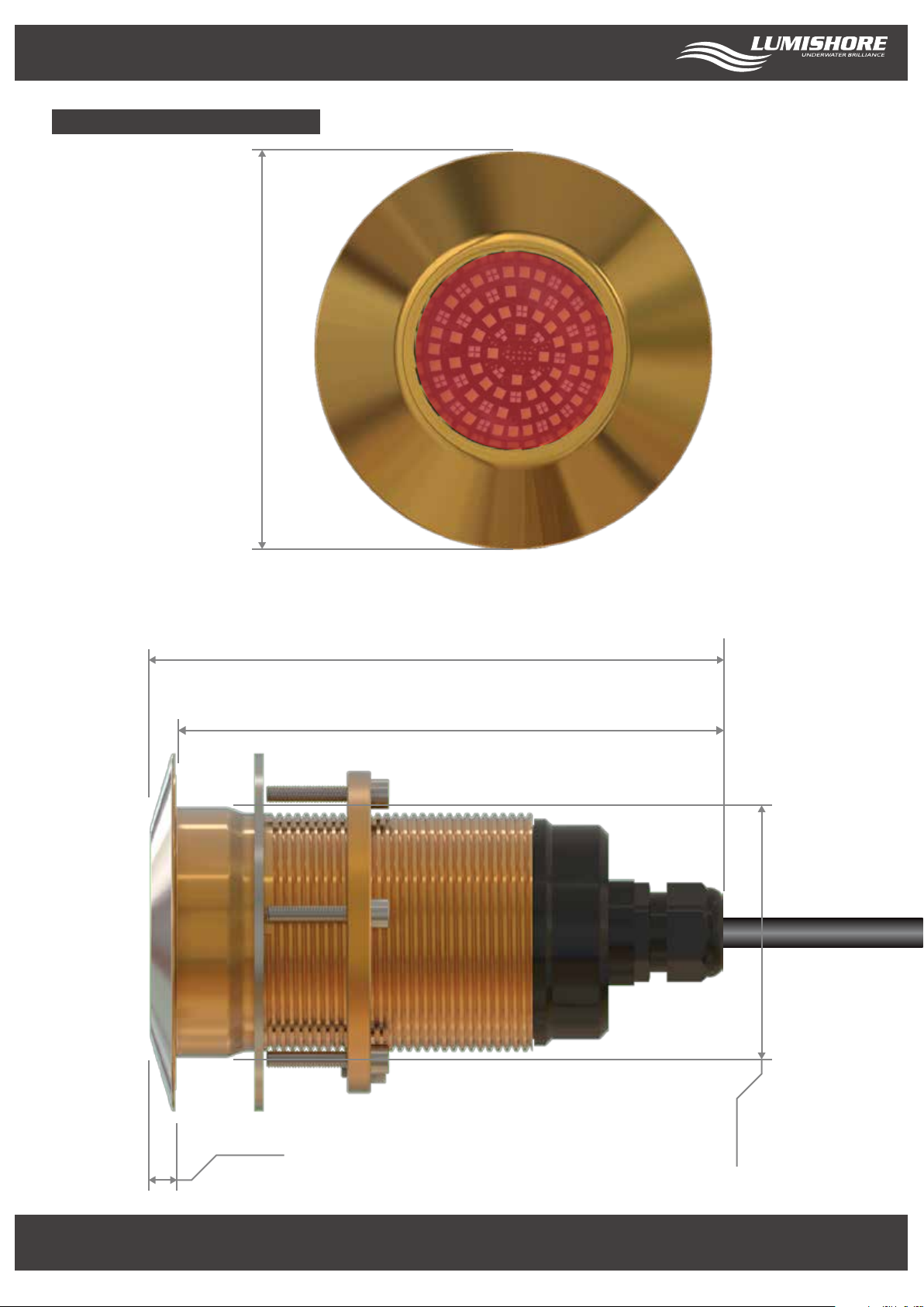
TIX 802 - Basic Dimensions
Light Unit
120mm
(4.72in)
LED ARRAY SHOWN
FOR ILLUSTRATION
PURPOSES ONLY
193mm
(7.60in)
184mm
(7.24in)
8.5mm
(0.34in)
Lumishore UK Unit 3, Technium 1, Kings Road, Swansea, SA1 8PH, UK | +44(0)208 144 1694 | Info@Lumishore.com
Lumishore USA 7137 24TH Court East Sarasota, Florida 34234 | (941) 405-3302 | Sales @LumishoreUSA.com
(3.31in)
84mm
www.Lumishore.com
6
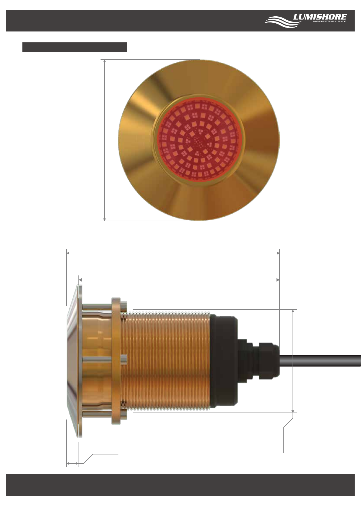
TIX 1602 - Basic Dimensions
Light Unit
140mm
(5.51in)
LED ARRAY SHOWN
FOR ILLUSTRATION
PURPOSES ONLY
195mm
(7.68in)
184mm
(7.24in)
11mm
(0.43in)
Lumishore UK Unit 3, Technium 1, Kings Road, Swansea, SA1 8PH, UK | +44(0)208 144 1694 | Info@Lumishore.com
Lumishore USA 7137 24TH Court East Sarasota, Florida 34234 | (941) 405-3302 | Sales @LumishoreUSA.com
(3.54in)
90mm
www.Lumishore.com
7

Light Installation
Tools Required
5mm Allen Wrench
1. Measure the position of the lights on a at part of the hull. Mark carefully, and double-check for internal obstacles.
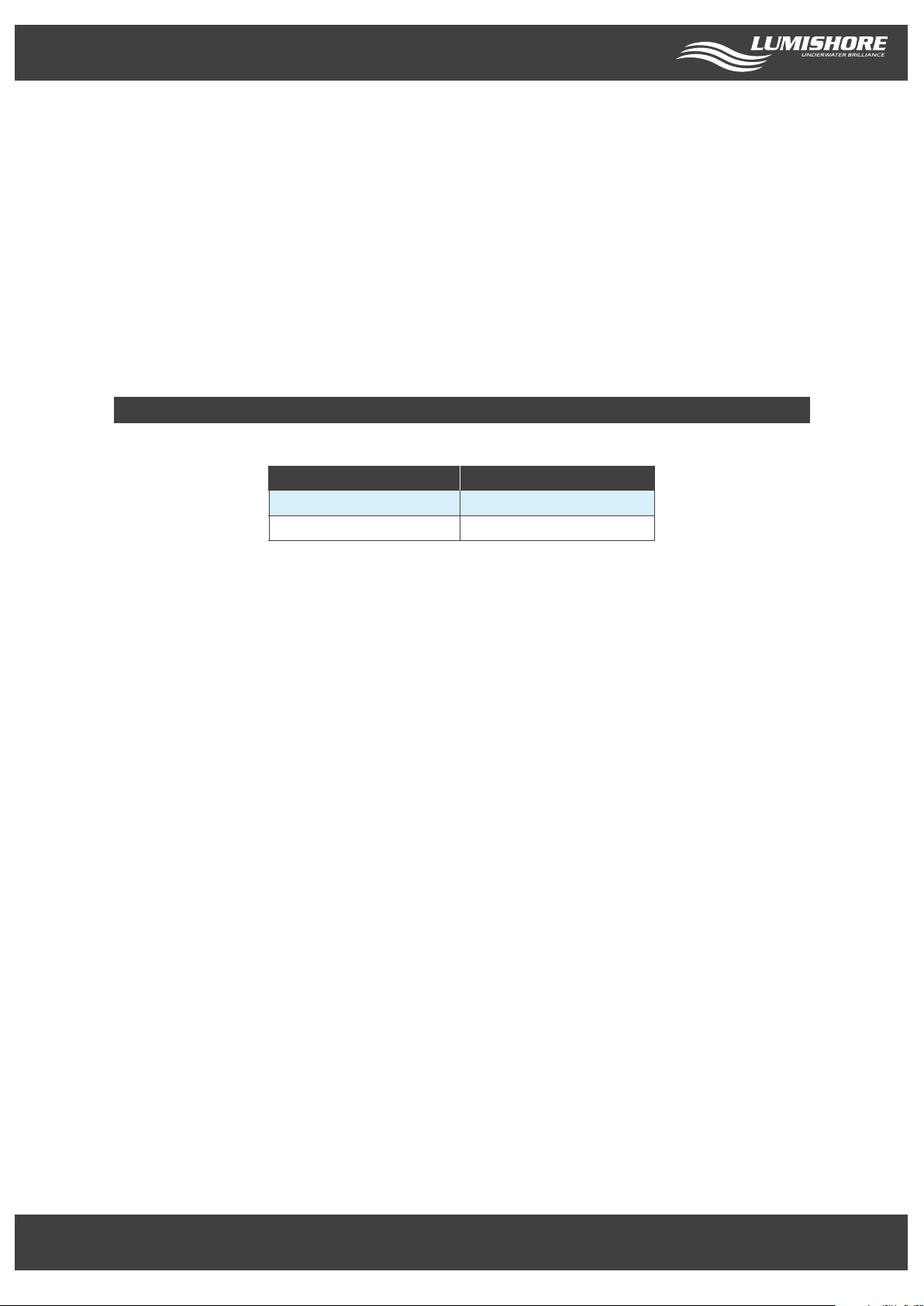
2. Check the required hole size against the table below. Drill a perpendicular hole through the hull using an appropriate
cutter for the hull material.
Model
TIX 802
TIX 1602
3. The exposed inner hull surface must be properly sealed to prevent water intrusion into the hull before the Thru-Hull
is secured in place.
4. Before inserting the Thru-Hull light ensure that the hull surface is free from dirt and grease and remove any existing
anti-foul from the hull surface.
Drill/Driver
Holesaw
Hole Size
86mm (3.375”)
92mm (3.625”)
Marine Sealant
(Use only 3M 4200)
Hole Size W/Delrin Sleeve
92mm (3.625”)
100mm (3.9375”)
Rags for clean-up
Rear Side
Note: Do not use an alcohol-based solvent as this may have an adverse eect on the sealant
5. Using an approved adhesive (3M 4200 Marine (recommended) or similar), apply liberally a continuous bead of sealant
around the entire circumference of the sealant groove, on the base of the stem and on the shaft of the Thru-Hull.
6. Feed the connector and cable through the hole in the hull avoiding any strain on the cable. Gently insert the stem of
the Thru-Hull light assembly through the hole in the hull.
7. Apply even pressure with a slight circular motion until the Thru-Hull is ush with the hull surface. Ensure the light
is orientated correctly. See page 9 for more information.
8. From inside the vessel, feed the supplied washer down the shaft of the Thru-Hull tting. Screw the locking nut in place
and tighten the retaining bolts so that they are hand tight (less than 1Nm) - Do not tighten fully at this stage, excess
pressure will push all of the sealant out.
9. Remove excess sealant that is squeezed from behind the light with a rag.
10. Allow the sealant to cure according to the sealant manufacturer’s instructions. Once fully cured, using a 5mm Allen
wrench, re-tighten each retaining bolt (force less than 3Nm). Care should be taken not to exceed this force as damage
to the light module or hull of the vessel may occur.
11. Attach the vessel’s bonding protection to the bonding bolt on the locking ring.
Apply sealant
Lumishore UK Unit 3, Technium 1, Kings Road, Swansea, SA1 8PH, UK | +44(0)208 144 1694 | Info@Lumishore.com
Lumishore USA 7137 24TH Court East Sarasota, Florida 34234 | (941) 405-3302 | Sales @LumishoreUSA.com
www.Lumishore.com
8

Light Installation - Continued
Ensure that each light module has correct vertical and horizontal alignment with the hull, and that the correct
orientation of the light module is achieved (refer to the module below).
Top
A2283
Front View
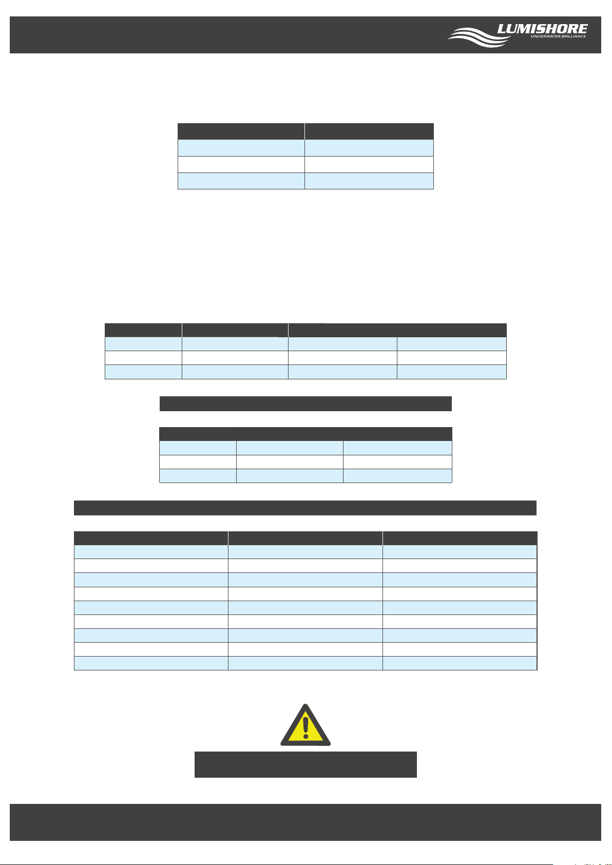
Max Currents
Model Max Current (12V DC) Max Current (24V DC)
TIX 802 8.8A
TIX 1602 N/A
NOTE : Refer to the EOS controller manual for set up instructions.
4.4A
6.5A
Ensure correct electrical polarity. Incorrect installation will invalidate warranty!
Lumishore UK Unit 3, Technium 1, Kings Road, Swansea, SA1 8PH, UK | +44(0)208 144 1694 | Info@Lumishore.com
Lumishore USA 7137 24TH Court East Sarasota, Florida 34234 | (941) 405-3302 | Sales @LumishoreUSA.com
www.Lumishore.com
9

Maintenance & Product Support
The underwater lighting system should always be tested before the boat goes back in the water. Check that each light comes
on and all lights change in sequence as per the system operation section above. See the problem solving guide for advice on
resolving any issues you may have. Once the boat is back in the water check for any water ingress around the installed lights.
Check again after several hours. Water ingress should be dealt with immediately. The lights should be checked several times
over the rst 24hrs and periodically after that to ensure installation is satisfactory.
Maintenance and Cleaning
The locking nut and retaining bolts should be inspected on a regular basis to ensure they are kept tight. LUMISHORE
recommends general inspection of the light module, driver and cable attachments every month.
LUMISHORE lights require simple cleaning. Lights should be checked often to ensure the light body and lens area
are free from sea growth. In the event that your light requires cleaning, we recommend the use of a soft cloth or
soft bristled brush. The glass should be kept clean with a plastic scraper or soft brush. Regular cleaning of the lens
will ensure that the light module delivers maximum optical output. DO NOT use an abrasive cloth or cleaning agent
as permanent damage to the lens may occur.
DO NOT use any abrasive cleaning materials as these may damage the body of the light.
DO NOT use any cleaning uids that contain solvents, acids or alkalis.
DO NOT clean using pressure washing or sandblasting equipment.
Slight discolouration of body may occur over life. This does not aect performance, and is not subject to warranty.
Due to nature and high build quality it may on rare occasions be possible to see small levels of condensation,
this is normal for high power LEDs and will disappear after cooling and does not harm operation in any way.
No chemicals, cleaners, chemical sprays or sandblasting should ever be applied / used on lights — this will
negate warranty
To prolong device lifetime and prevent marine growth build up, a good quality anti-fouling system must be used to
coat the external body of the device. This should be renewed regularly.
Product Support
If you have questions or comments, please e-mail info@lumishore.com or call USA (941) 405-3302,
United Kingdom +44(0)208 144 1694, or France +33(0)493 582 537.
Lumishore UK Unit 3, Technium 1, Kings Road, Swansea, SA1 8PH, UK | +44(0)208 144 1694 | Info@Lumishore.com
Lumishore USA 7137 24TH Court East Sarasota, Florida 34234 | (941) 405-3302 | Sales @LumishoreUSA.com
www.Lumishore.com
10
Warranty & Troubleshooting
Warranty
LUMISHORE Ltd warrants the Thru-Hull lighting system to be free from defects in workmanship for a period of 3
years, starting from the date of original purchase. Should your lighting system have a problem during this period,
please contact your dealer as soon as you become aware of the defect.
Misuse, abuse, improper installation, neglect, improper shipping, damage caused by disasters (e.g. re, ood and
lightning), installation by unqualied personnel, unauthorized repair or modication will void this warranty.
For the avoidance of confusion and doubt, non compliance with all installation, maintenance and operating
instructions in this document constitute non conformance with warranty terms.
Full warranty details are available at www.lumishore.com.
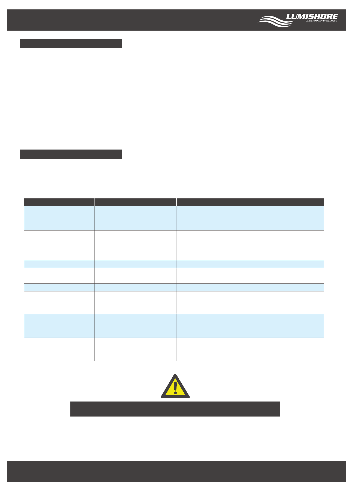
Troubleshooting
In the event of one or more of the lights not lighting up then check the LED status on the back of the light. The LED
will either be continually ON (healthy), OFF (no power to driver) or ashing. Please refer to the table below for what
the number of ashes means and what action to take.
LED Status
No LED light
Solid LED
Flashing 2 times
Flashing 3 times
Flashing 4 times
Flashing 7 times
Flashing 8 times
Continuous rapid ashing
Meaning
No power to light
Power On
Low input voltage to driver
Light temp too high
Internal Driver temp too high
LED array voltage out of range
Light not detected
Internal Driver program corrupt
Action to take / Things to check
Check fuse / breaker
Check connections
Check voltage at input to light connections
Light is receiving voltage and operating properly
Check the controller is operating correctly
Check EOS/DMX connections
Check intensity is turned up
Check power connections or battery voltage
Could happen when light is out of water or next
to exhaust
Light is mounted too close to an engine or exhaust
Disconnect power for 30 seconds, re-connect and check.
If problem persists, disconnect light and contact
LUMISHORE for help
Disconnect power for 30 seconds, re-connect and check.
If problem persists, disconnect light and contact
LUMISHORE for help
Reset driver by switching o power for 1 minute, and
then switching on again
Contact LUMISHORE if problem persists
If a light does not switch on, or function normally, it should be disconnected from the power source
Thank you!
For purchasing LUMISHORE lights
Lumishore UK Unit 3, Technium 1, Kings Road, Swansea, SA1 8PH, UK | +44(0)208 144 1694 | Info@Lumishore.com
Lumishore USA 7137 24TH Court East Sarasota, Florida 34234 | (941) 405-3302 | Sales @LumishoreUSA.com
www.Lumishore.com
11
 Loading...