


SMX23-SUPRA
Dual Color Surface Mount
12 VOLT ONLY
IP-68
Before you Start
www.Lu mishore. com
45-0100 - Rev 2.0
Lumishore UK Unit 2, Technium 1, Kings Road, Swansea, SA1 8PH, UK | +44(0)208 144 1694 | Info@Lu mishore.com
1
M Class Dual Color
Surface Mount Underwater Light
INSTALLATION AND OPERATION INSTRUCTIONS
Congratulations! You have purchased a LUMISHORE advanced LED
technology underwater lighting system. Every care has been taken to
ensure your compact SMX 23 LED light arrives in perfect condition, so
please enjoy the ultimate experience in underwater lighting.
Adding underwater lighting to your vessel has never been easier - one
small cable hole and three mounting screws is all it takes.
Please read the following pages to ensure a complete understanding
of the LUMISHORE LED lighting system before installation.
12V DC ONLY
• Always ensure that the vessel’s power source and battery are
disconnected or isolated prior to installation.
• A qualied professional should carry out both the electrical and
mechanical installation.
• For best underwater illumination, LUMISHORE recommends installation 4” to 12” (100-300mm) below the minimum load water line.
• Choose a location - The light must be mounted on a at (not
curved) surface. For underwater installs mount on transom or side
hull only.
• A hole will be drilled to allow the cable to be inserted; care must be
taken to ensure there is unrestricted access inside the hull.
• When installing three or more lights, equal spacing 2.5’- 3’ is recommended to give a consistent light pool.
• The light is temperature sensitive and must not be located close to
the exhaust outlet or other heat source.
• SMX 23 Lights operate on 12V DC ONLY. Never connect a light
directly to the mains AC voltage, or DC voltage other than that specied.
• Each light should be individually fused with a 4A fuse.
• For Installation on boats up to 7.5m (25 ft)
Mechanical Installation
Tools: Drill, drill bits, marine sealant (3M 4200 recommened), Cross
head screwdriver, rags for clean-up:
1. Select a suitable at surface that is accessible from behind and
ensure the cable can be run without a problem.
2. With one hole at the bottom centre, mark and drill the pilot holes
for the screws. Drill the power cable hole. The cable hole must be
recessed on the outside of the hull to accept the cable gland on the
back of the light, so that the lights sits ush.
Note: Cored hulls must be sealed prior to tting the lights - refer to
the manufacturers instructions.
3. Clean and prepare the hull ready for the sealant.
4. Apply a continuous thick bead of sealant to the back of the light,
making sure the recess on the outer edge is slightly overlled. Also
apply a bead of sealant around the cable gland. Refer to image
above.
5. Push the power cable through the hole and align the light with the
pilot hole screws.
6. Attach the light using the 3 supplied screws by hand tightening
with a screwdriver.
IMPORTANT: Do Not Over Tighten. Do Not Use Power Tools to tight-
en screws.
7. Use a damp cloth to wipe o excess sealant that has squeezed out
around the light. DO NOT use chemical cleaners or solvents.
IMPORTANT: Refer to the directions on the sealant to make sure it
has fully cured before launching the boat into the water.
70 mm
(2.75in)
17mm
(0.67in)
12mm
(0.47in)
PCD 61mm
(2.40in)
120°
Rear side
Apply sealant
Bottom center
Pilot Hole for Screws - 9/64” / 3.5mm
Hole for Cable - 7/32” / 5.5mm
Recess for Gland - 17/32” / 13.5mm hole to a depth of 5/8” / 15mm
45-0100 - Rev 2.0
45-0100 - Rev 2.0
2
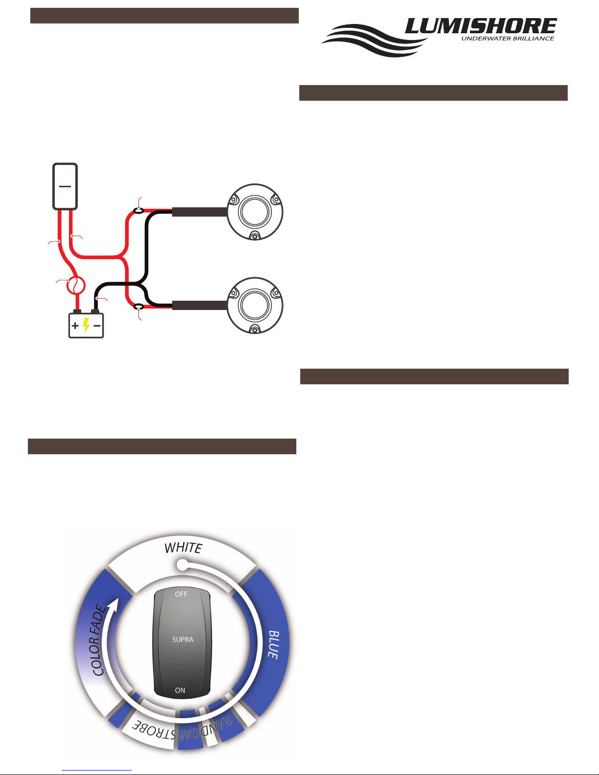
Electrical Installation
www.Lu mishore. com
Plan the cable route prior to instalation. Ensure all cables are correctly
rated. Each light must be individually fused with a 4 A fuse. The cable
connections are:
Red 12V DC
Black Ground
An ON / OFF switch should be installed to select the modes of operation.
All connections must be made waterproof.
Cleaning and Maintenance
The light cables can be extended. Ensure the correct cable gauge is
used to avoid issues with voltage drop. Follow ABYC recommendations for no more than 3% voltage drop. Consult a qualifed electrical
installer, or contact Lumishore for further information.
Make sure the lights are tested, and working as expected before the
boat goes back in the water.
LUMISHORE Ltd warrants the SMX23 to be free from defects in
workmanship and materials for a period of two years, starting
from the date of original purchase. Misuse, abuse, improper installation, neglect, improper shipping, damage caused by disasters
such as re, ood, and lightning, installation by unqualied
personnel, unauthorized repair or modication will void this
warranty. For the avoidance of confusion and doubt, non-compliance with all installation, maintenance and operating instructions
in this document constitute non-conformance with warranty
terms
.
Warranty
LUMISHORE lights require simple cleaning. Lights should be
checked often to ensure the light body and lens area are free from
sea growth. In the event that your light requires cleaning, we
recommend the use of a soft cloth or soft bristled brush.
• DO NOT use any abrasive cleaning materials as these may
damage the body of the light.
• DO NOT use any cleaning uids that contain solvents, acids or
alkalis.
• DO NOT clean using pressure washing or sandblasting equipment.
Slight discolouration of body may occur over life. This does not
aect performance, and is not subject to warranty.
Due to nature and high build quality it may on rare occasions be
possible to see small levels of condensation, this is normal for high
power LEDs and will disappear after cooling and does not harm
operation in any way.
If the lens of the light is covered for any reason, e.g maintnence, or
painting DO NOT switch the lights on until the covers are
removed.
Operating the Lights
The lights operate in White, Blue, Random Strobe, and Colour Fade
modes. To change the mode turn the switch OFF / ON (within 2
seconds). To reset to White mode, switch the lights o for 5
seconds. The lights will always come on in White mode when rst
switched on.
Fuse or
Circuit
Breaker
Battery
Red
(+VDC)
Red
(+VDC)
Black
(GND)
Fuse
Fuse
Switch
O
On
Use correct cable gauge consult ABYC recomendations
for MAX 3% voltage drop
 Loading...