

Page 1
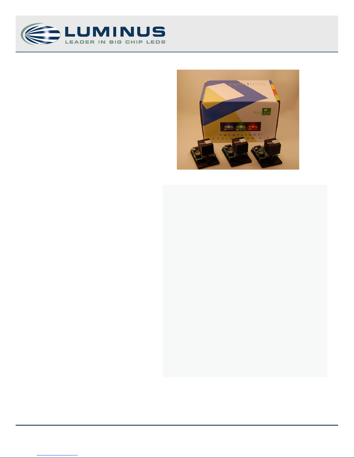
Development Kit Manual
DK-114N-1 and DK-114N-3
Overview
Big Chip LEDs from Luminus Devices have been designed
from the ground up to enable a new class of illumination and
projection systems. Beneting from a suite of innovations in
chip technology, packaging, and thermal management, Big
Chip LEDs allow designers to achieve ecient light engine
designs and deliver high brightness solutions.
The DK-114N series development kit is a comprehensive solution designed specically to support the development of
single and three channel PT and CBT series Big Chip LEDs.
Each channel of the kit, comprising of a high current driver, an
ecient thermal management solution and cables is capable of sourcing a drive current of 14 A and ensures that CBT
and PT series LEDs are operated at up to 70 W for maximum
brightness. This plug and play solution can easily be connected to common laboratory equipment through standard connectors and allows system designers to save weeks in their
development cycles.
DK-114N series - Development Kit Manual
Table of Contents
1. Key Features ..............................2
2. Development Kit Contents ................2
2.1 Heat Sink and Driver Board .............2
2.2 Cable Assembly ........................3
2.3 TIM and Mounting Hardware ...........4
3. User Instructions .........................4
3.1 Device Mounting Instructions ..........5
3.2 Electrical Connections ..................6
3.3 Operation .............................6
4. Appendix .................................9
1
960017 Rev C © 2013 Luminus Devices, Inc. - All Rights Reserved
Luminus Devices, Inc. • T 978.528.8000 • www.luminus.com
1100 Technology Park Drive • Billerica, MA 01821
Page 2
DK-114N series - Development Kit Manual
1. Key Features
• Drive any CBT or PT series Big Chip LED up to 14 A
• Pulse frequencies of greater than 40 kHz possible
• Analog current control via on-board potentiometer or external voltage
• Simple current and voltage measurements
• Fast rise and fall times - less than 1 microsecond
• Fast current level switching - less than 5 microseconds
2. Development Kit Contents
The DK-114N-1 and DK114N-3 are similar in all aspects; while the DK-114N-1 supports one channel, the DK-114N-3 supports three channels.
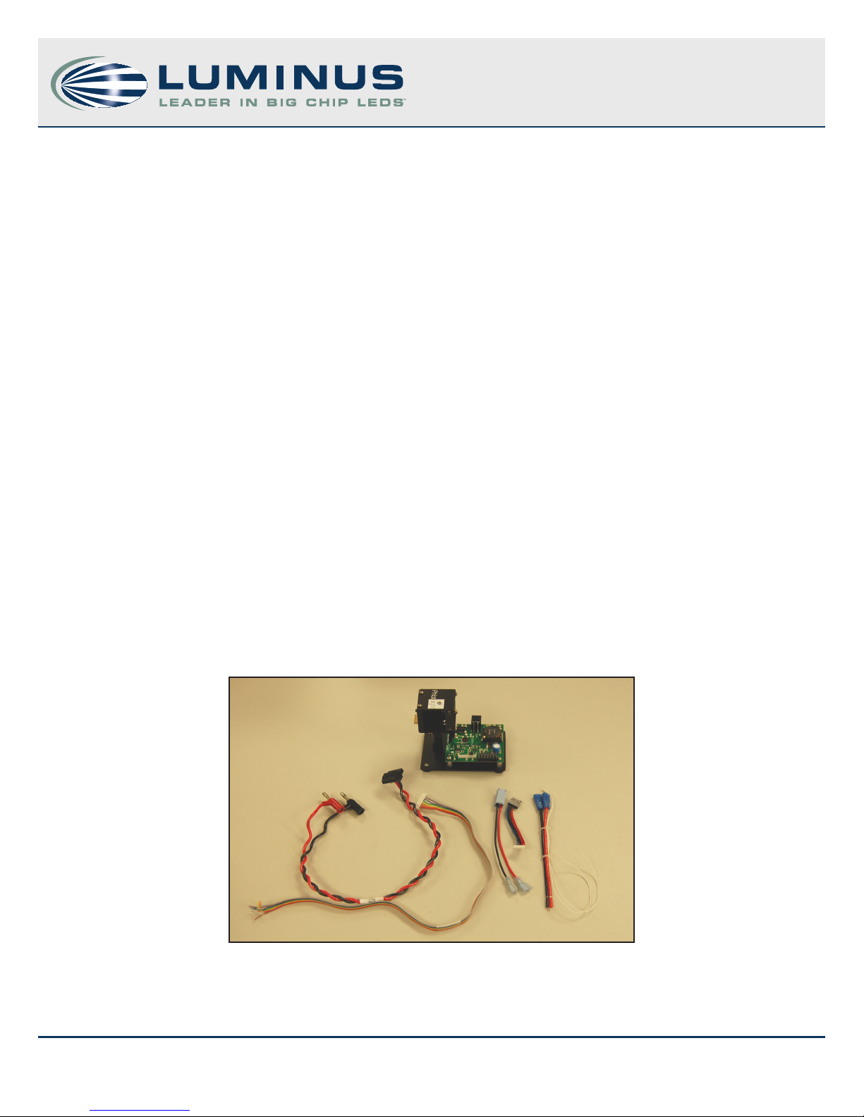
All instructions in this manual are based on the DK-114N-1 and can easily be replicated in the DK-114N-3. As shown in Figure 1, the DK114N-1 consists of :
• Heat sink and driver board
• Cable assemblies
• Thermal interface materials and mounting hardware
• User Manual
Figure 1: Contents of DK-114N-1
A list of contents of the development kit is given in Appendix A. This development kit is designed with exible features to allow easy
evaluation of the Big Chip LEDs but is not optimized for size or for direct integration into end products. However, the underlying circuit
2
960017 Rev C © 2013 Luminus Devices, Inc. - All Rights Reserved
Luminus Devices, Inc. • T 978.528.8000 • www.luminus.com
1100 Technology Park Drive • Billerica, MA 01821
Page 3
DK-114N series - Development Kit Manual
and thermal design can be used as a reference by system designers; to this eect, design les including schematics, mechanical drawings,
and bill of materials are available upon request. PT, CBT, and CST series LEDs are built in the common anode conguration. To enable driving
these LEDs, the driver circuit, based on National Semiconductor’s LM3433 IC, is congured in the grounded common anode topology (refer
Appendix B), which enables anodes of multiple LEDs to be in electrical contact with each other without necessitating electrical isolation.
Further design support for the driver can be obtained at http://www.national.com.
2.1 Heat-Sink and Driver Board
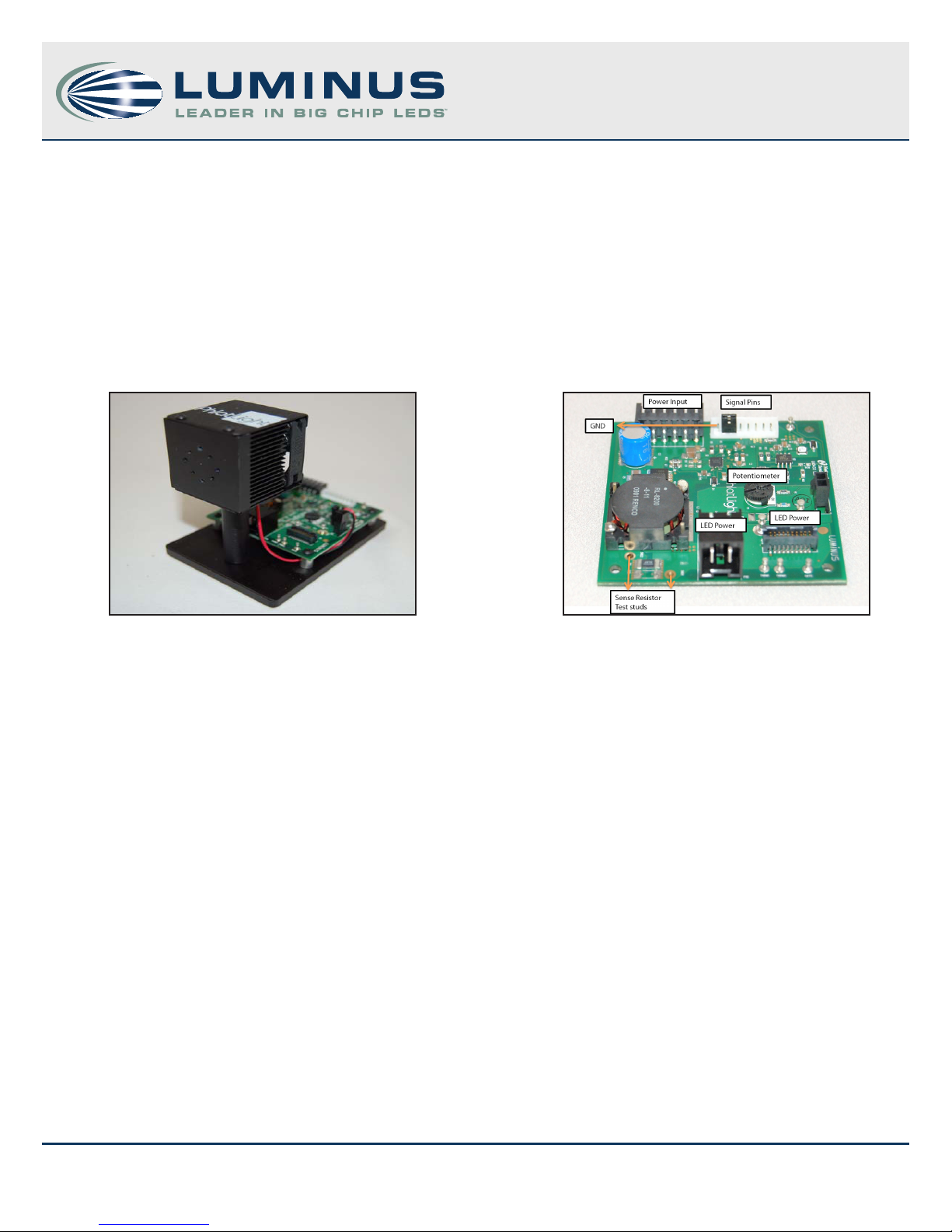
The heat sink, measuring only 40 mm x 40 mm x 40 mm is a high performance, low cost, compact air cooled aluminum extrusion, and
enables signicant power dissipation to the ambient by virtue of its low thermal resistance (0.6 º C/W ). The bolt pattern on the front allows
for easy mounting of all CBT and PT series modules.
Figure 2: Heat sink Figure 3: Driver board
The driver board, designed with National Semiconductor’s LM3433 IC (Figure 3), is mounted close to the heat-sink allowing for minimal
cable lengths (<3”) which help prevent current ringing when pulsing LEDs. The driver board, because of its grounded common anode
topology, requires a -12 V DC input with respect to ground and can provide up to 14 A to LEDs in either CW or pulsed mode. PWM dimming
is achieved with a 0-5 V signal from a function generator and frequencies up to 40 kHz are supported. Figure 3 depicts the layout of the
driver board along with the commonly used pins and readouts. The signal pins are used to achieve external current control and provide
PWM dimming; the orientation of these pins is also shown, starting with pin 1(GND) on the left. Appendix C lists the pin-out for the signal
pins.
Note: The heat sink conducts power even though it is grounded.
2.2 Cable Assembly
Each development kit includes the following cables:
• Power supply to driver board cable
• Driver board to LED cables
• Signal cable
• Thermistor cable
3
960017 Rev C © 2013 Luminus Devices, Inc. - All Rights Reserved
Luminus Devices, Inc. • T 978.528.8000 • www.luminus.com
1100 Technology Park Drive • Billerica, MA 01821
Page 4
DK-114N series - Development Kit Manual
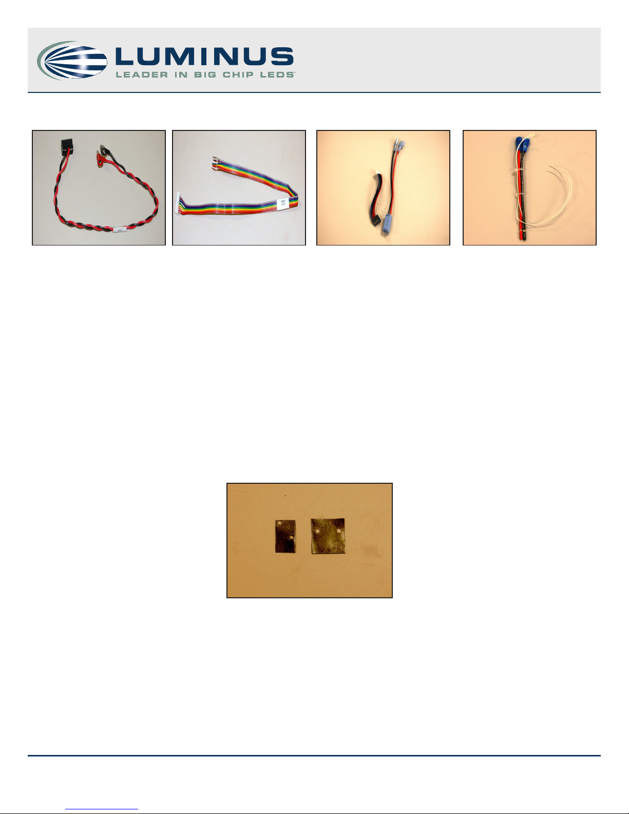
The gures below illustrate the cables included in the DK-114N-1.
Figures 4-7: From left to right: Power supply to driver board cable, Signal cable, Driver board to LED cable, Thermistor cable
Figure 6 depicts two types of driver board to LED cables: the shorter cable (with either 8 - or 10- pins on the LED connector) on the left,
used with LEDs such as PT39, PT40, CBT-40 and PT54, and the longer cable with the two spade connectors on the right, used with LEDs
such as the CBT-90, PT-120 and CBT-120. There are ve dierent variants of the shorter driver board to LED cable : 960011 to be used with
PT39, PT54 and CBT-40; 960043 to be used with PT40-RA; 960044 to be used with PT40-G/B; 960045 to be used with PT54-TE-RA and 960046
to be used with PT54-TE-G/B. These ve cables have labels that contain the cable number and the LEDs to which they connect--users must
match the LED they use to the appropriate cable since connecting an incorrect cable can damage the LED. For optimum performance, and
to avoid ringing when pulsing the LEDs, increasing the length of the driver board to LED cable is not recommended.
2.3 Thermal Interface Material (TIM) and Mounting Hardware
The development kit includes precut sheets of eGraf HiTherm 1205, a high performance thermal interface material, and M2x5, M2.5x6
screws required for mounting the LEDs.
Figure 7: TIM sheets
3. User Instructions
The following sections explain the set-up and operation of the DK-114N-1 Development Kit. Additional lab equipment such as a 12 V
laboratory power supply, an oscilloscope, a waveform generator, a multimeter and a photodetector are required to power and use the
DK-114N-1. Table 1 lists a recommended model for the equipment and Appendix D provides an additional list of compatible power
supplies. The use of a table equipped with ESD protection is recommended.
4
960017 Rev C © 2013 Luminus Devices, Inc. - All Rights Reserved
Luminus Devices, Inc. • T 978.528.8000 • www.luminus.com
1100 Technology Park Drive • Billerica, MA 01821
Page 5
DK-114N series - Development Kit Manual
Table 1: Additional Lab Equipment
Lab Equipment Model
12 V Lab Power Supply Lambda ZUP20-20
Oscilloscope Tektronix TDS 3024B
Waveform Generator Agilent 33220A
Multimeter Fluke 187
Photodetector Thorlabs PDA10A
3.1 Device Mounting Instructions
Ineective heat sinking may lead to premature LED degradation or failure. The following steps explain how a device is mounted on the
heat sink while ensuring good thermal contact between the copper core-board and the heat sink:
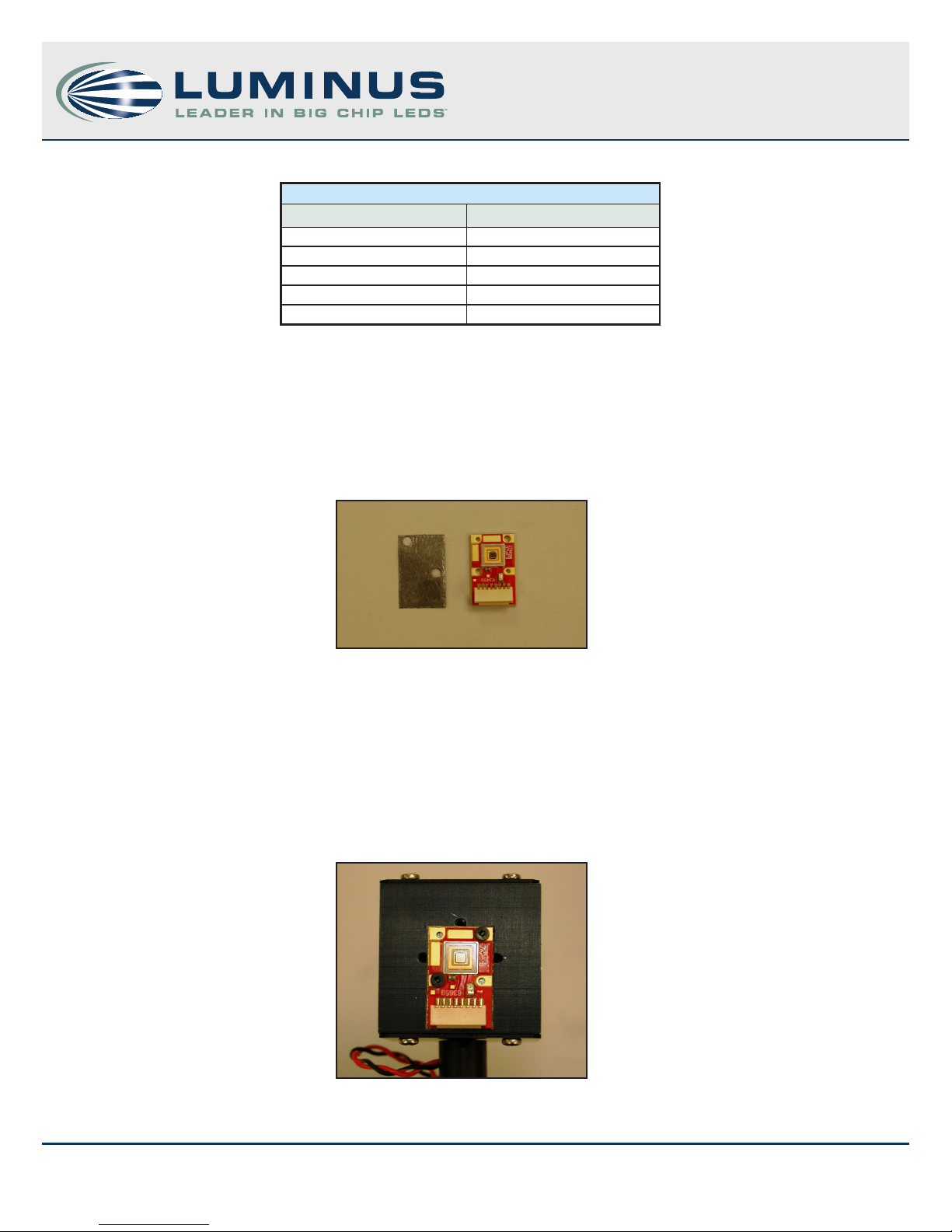
1. Use a thermal interface sheet that is slightly larger than the core-board (Figure 7).
Figure 8: PT-39 LED and an appropriate TIM sheet
2. The heat sink surface must be free of dust particles. Place the thermal interface sheet on the heat sink with its pre-drilled holes matching
the holes on the heat sink .
3. Place the device on the thermal interface sheet.
4. Insert screws in the holes of the coreboard and tighten. To ensure equal pressure is exerted by all screws, alternate tightening each screw
until the board is securely fastened. The device is now mounted and ready for electrical connections (Figure 9).
Figure 9: LED mounted on heat sink
5
960017 Rev C © 2013 Luminus Devices, Inc. - All Rights Reserved
Luminus Devices, Inc. • T 978.528.8000 • www.luminus.com
1100 Technology Park Drive • Billerica, MA 01821
Page 6
DK-114N series - Development Kit Manual
3.2 Electrical Connections
1. The power supply being used must be capable of providing sucient power to drive the LED. Preset the output voltage to 0 V and keep
the power supply switched o until all connections are established. The positive terminal of the power supply should be at ground; the
negative terminal would then supply a negative voltage with respect to ground.
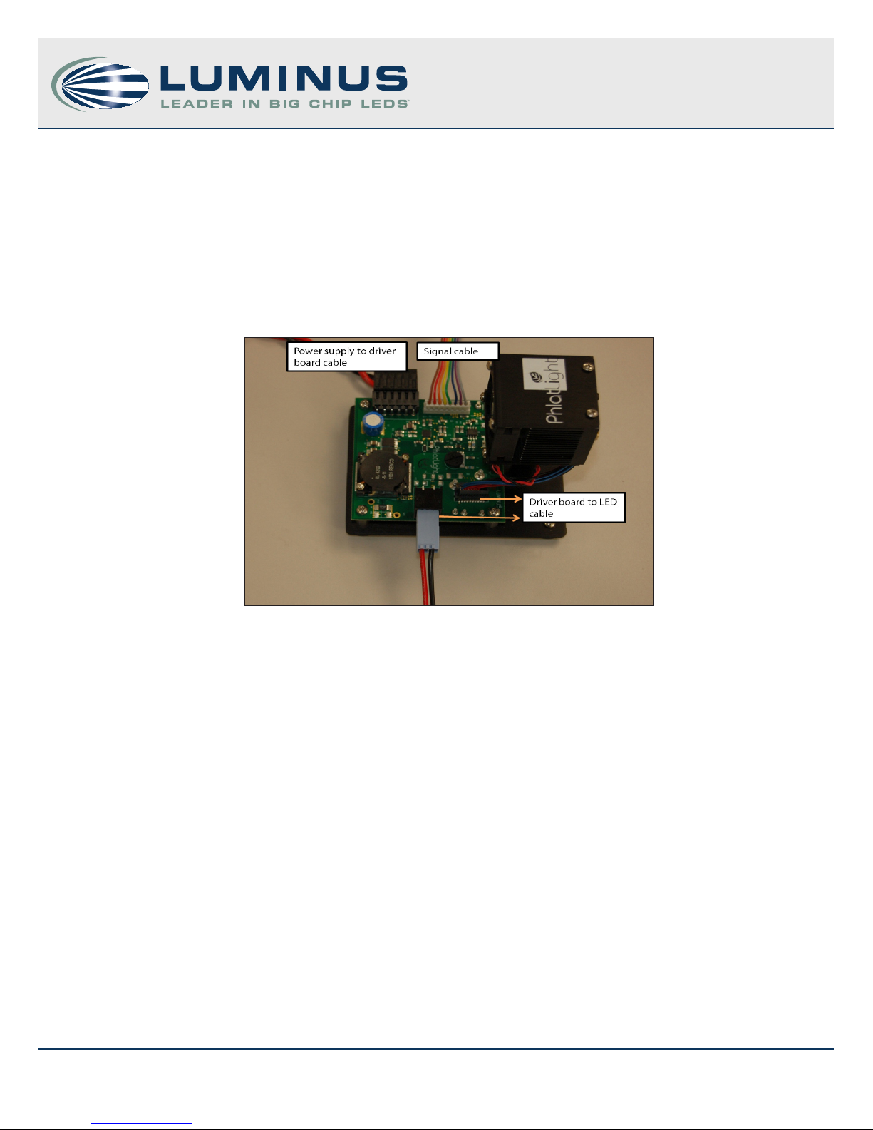
2. Connect the driver board to the LED and the power supply using the cables provided in the kit . The choice of the driver board to LED
cables is based on the LED connector— LEDs such as PT-39, PT-54 and CBT-40 require the appropriate variant of the shorter 3 “ cable while
LEDs such as CBT-90, PT-120 and CBT-120 with the 2 pin spade connector require the longer cable. Figure 10 illustrates the electrical
connections to the driver board; while both types of driver board to LED cables are shown for illustration, only one is required.
Figure 10: Completed electrical connections on DK-114N-1
3. Use the jumper provided with the driver board to short signal pins 2 and 3 (see Figure 3 and Appendix C). These pins correspond to
Analog ADJ and POT; shorting them enables the on-board potentiometer. Alternatively, the jumper can be removed and signal cable can
be used to short the Analog ADJ and POT pins.
4. Set the POT to the minimum current setting by rotating it fully counter-clockwise. The embedded arrow should point towards the “10”
on the POT.
5. The development kit is now ready to be powered on. Turn on the power supply and increase the source voltage to -12 V with respect to
ground. The driver will draw about 1-2 A current.
CAUTION: Do not set the power supply higher -12 V; doing so may damage the driver.
3.3 Operation
The DK-114N-1 can be used to drive LEDs in continuous-current controlled mode via the on-board POT or through an external analog
voltage. Additionally, each channel has inputs for PWM dimming using an external function generator and supports frequencies up to
40 kHz.
1. Current control via the on-board POT is achieved by shorting the Analog ADJ and POT pins. Clockwise rotation of the POT increases the
current, while counter-clockwise rotation decreases the current.
6
960017 Rev C © 2013 Luminus Devices, Inc. - All Rights Reserved
Luminus Devices, Inc. • T 978.528.8000 • www.luminus.com
1100 Technology Park Drive • Billerica, MA 01821
Page 7
DK-114N series - Development Kit Manual
V
CAUTION: The driver board is capable of providing 14 A to any LED. LEDs has dierent drive current limitations and care must be taken not
to exceed these limitations. Consult product data sheets for current and junction temperature limitations of specic LEDs.
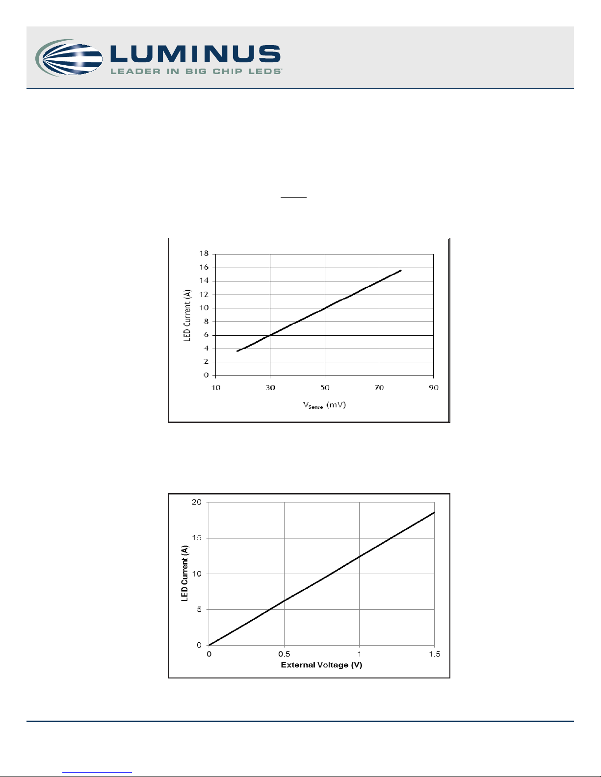
2. To determine the current through the LED, measure the voltage across the sense resistor test studs (see Figure 3). Figure 11 shows the
relationship between the sense resistor voltage (V
) and the LED current, (I
sense
), which is also calculated using:
LED
R
Sense
Sense
where the sense resistance, R
= 0.005 Ω.
sense
I =
LED
Figure 11: LED Current as a function of V
sense
3. To control the current externally, connect the positive of a 0-5 V signal to the Analog ADJ pin and the negative to the GND pin, using
the signal cable. Figure 12 shows the relationship between the LED current and the external voltage.
Figure 12: LED Current as a function of External Voltage
7
960017 Rev C © 2013 Luminus Devices, Inc. - All Rights Reserved
Luminus Devices, Inc. • T 978.528.8000 • www.luminus.com
1100 Technology Park Drive • Billerica, MA 01821
Page 8
DK-114N series - Development Kit Manual
4. To modulate the LEDs through PWM, connect the 0-5 V pulsed output of a waveform generator across the PWM and GND pins on
the signal cable, with the PWM pin at a positive voltage with respect to GND. 5 V represents O and 0 V represents On. The Analog
ADJ and POT pins must be shorted; this allows for the LED’s peak current to be controlled via the on-board POT. Proper operation is
best monitored by using a photo detector to observe the light output from the LED. Note: Exceeding 5 V on the PWM pin may cause
permanent damage to the driver board.
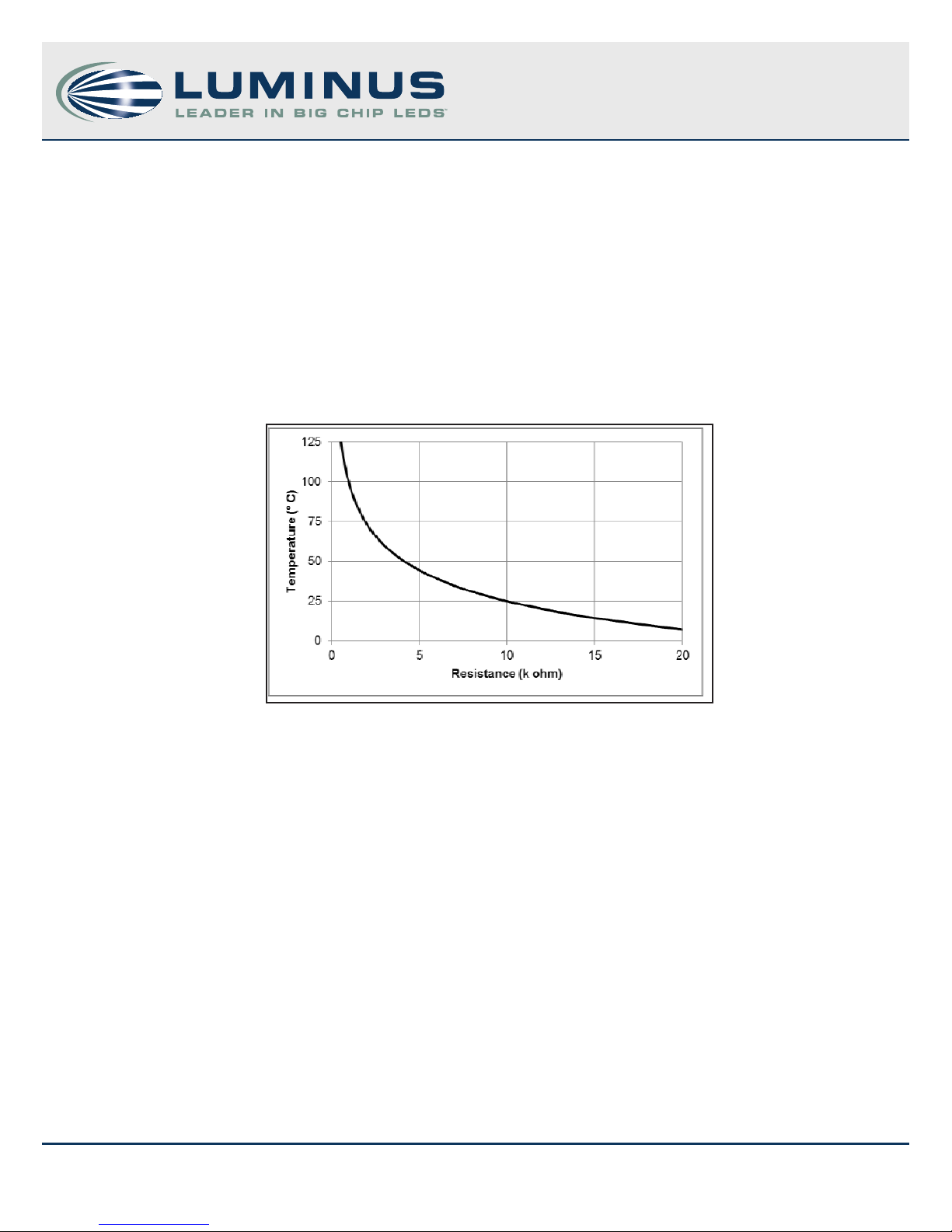
5. Coreboard temperature of the Big Chip LEDs is monitored using a Murata Manufacturing Co. thermistor (part number
NCP15XH103J03RC). When using the short 8-pin cable, the on board thermistor is connected to test points THRM1 and THRM2 on
the driver board. Signal Pins 7 and 8 are also thermistor test points and are equivalent to THRM2 and THRM1. Figure 13 shows the
relationship between the thermistor (coreboard) temperature and the resistance between the thermistor test points. Note that there
is a temperature rise from the thermistor to the LED junction; for guidance on estimating the LED junction temperature (Tj), refer to
appropriate product datasheets. To monitor coreboard temperature when using the two pin driver board to LED cable, the thermistor
cable (Fig 7) must be connected to the on board thermistor. The resistance across the cable’s leads can then be used to monitor
temperature.
Figure 13: Coreboard temperature as a function of thermistor resistance
8
960017 Rev C © 2013 Luminus Devices, Inc. - All Rights Reserved
Luminus Devices, Inc. • T 978.528.8000 • www.luminus.com
1100 Technology Park Drive • Billerica, MA 01821
Page 9
DK-114N series - Development Kit Manual
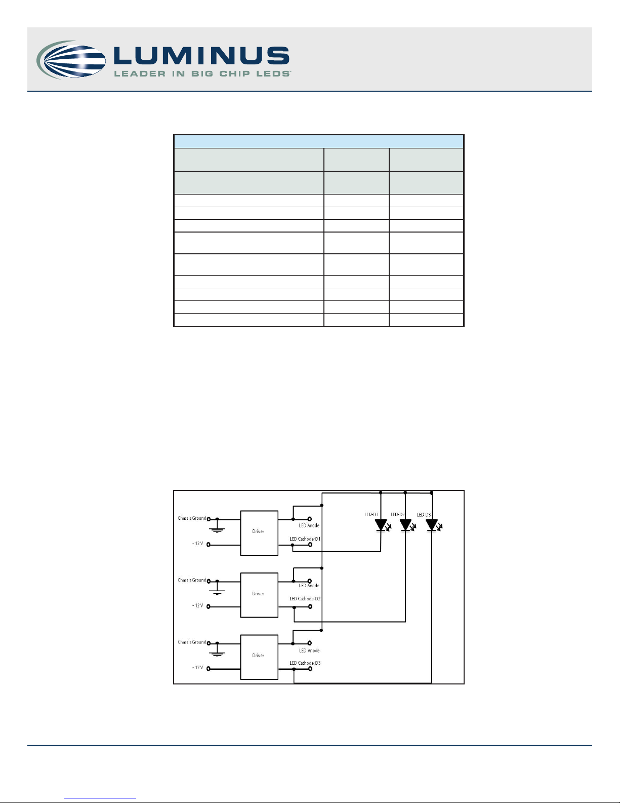
Appendix A: Contents of DK-114N-1 and DK-114N-3
Table 2: Table of Contents
DK-114N-1 DK-114N-3
Description Quantity Quantity
Driver board 1 3
Heat sink with mounting screws 1 3
Power supply to driver board cable 1 3
Driver board to LED cable (short, 8-pin
or 10-pin LED connector)-ve variants
Driver board to LED cable (long, for 2-
pin spade connector)
Signal cable 1 3
Thermistor cable 1 3
TIM sheets 4 12
User Manual 1 1
1 each 3 each
1 3
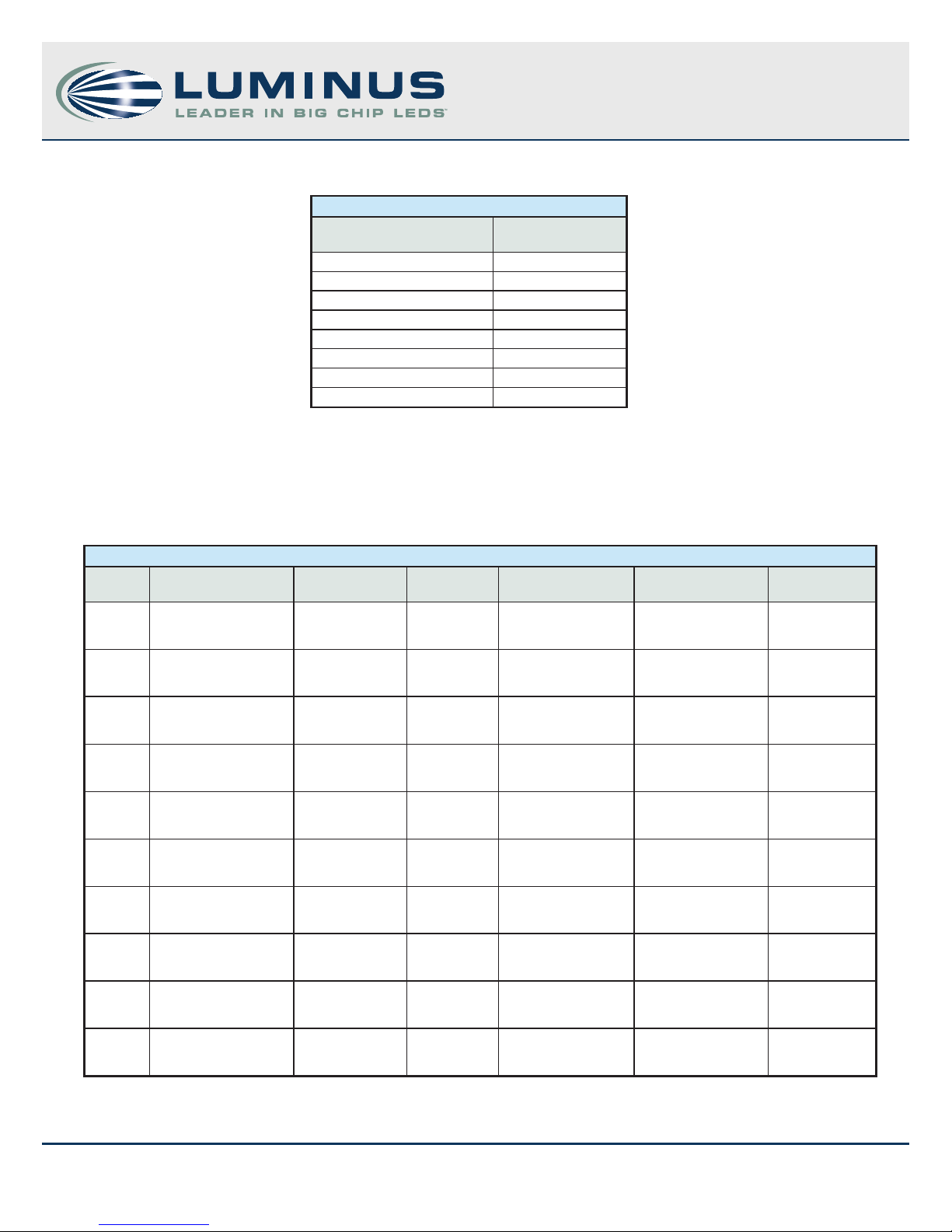
Appendix B: Grounded Common Anode Topology
PT, CBT and CST series Big Chip LEDs are built with a common anode conguration, where the copper coreboard is at a positive
electrical potential with respect the LED cathode. In a system with multiple LEDs in direct contact with a common heat sink, the
common anode conguration causes poses a challenge to electrically addressing and isolating individual LEDs. The driver board in
the DK-114N-1, based on National Semiconductor’s LM3433 IC, addresses the challenge of connecting multiple common anode LEDs
by utilizing a grounded common anode topology, i.e., the anode is kept at ground and the cathode is at a negative potential, thus
enabling LEDs to be in contact directly with the heat sink. A basic schematic, using three grounded common anode LEDs is shown
below in Figure 14. It is important to note that while the heat sink is at ground, there is still power passing through it.
Figure 14: Grounded common anode conguration
9
960017 Rev C © 2013 Luminus Devices, Inc. - All Rights Reserved
Luminus Devices, Inc. • T 978.528.8000 • www.luminus.com
1100 Technology Park Drive • Billerica, MA 01821
Page 10
DK-114N series - Development Kit Manual
Appendix C: Driver Board Pin-out
Table 3: Signal pin out
Pin Description
Pin 1 GND
Pin 2 Analog ADJ
Pin 3 POT
Pin 4 Enable
Pin 5 PWM
Pin 6 Vinx
Pin 7 Thermistor
Pin 8 Thermistor
Appendix D: Isolated AC/DC Power Supplies
Table 3 lists a few isolated AC-DC power supplies. A power supply with isolated outputs is required to properly drive the common anode
LEDs and failure to use an isolated power supply may damage the driver board. For best eciency, select a power supply that closely
matches the required power.
Table 4: Isolated AC/ DC power supplies
Power Manufacturer Input Output V/I Size Mounting Part #
30 W CUI Inc.
50 W Omron
50 W Lambda Power
60 W Globtek Inc.
75W Lambda Power
100 W Lambda Power
100 W Elpac Power
120 W AULT Inc. AC
125 W
Power-One Solutions
85-264 VAC
(47-400 Hz) 12 V / 2.5 A 3.7” x 2” x 0.85” Thru-hole/SMT FSK-S30-12U
85-264 VAC
(47-63 Hz) 12 V / 4.2 A 5” x 3.34” x 1.57” DIN Rail S8SP-05005
90-264VAC
(47-63Hz) 12 V / 3 A 3.62” x 1.46” x 6.26”
90-264 VAC
(47-440Hz 12 V / 5 A
90-264 VAC
(47-63Hz) 12 V / 6.3 A 3.7” x 1.69” x 6.69”
90-264 VAC
(47-63Hz) 12 V / 8.5 A 3.78” x 1.77” x 7.4”
100-264 VAC
(47-63Hz) 12V / 8.3
100-264 VAC
(47-63Hz) 12 V / 10 A 9” x 2.9” x 2” Medical/External
90-264 VAC
(47-63Hz) 12 V / 10.5 A 5” x 3” x 1.25” Open Frame MBP125-1012
5.24” x 2.39” x
1.62” External/Desktop DPS50
7.36” x 4.33” x
2.32” External/Desktop
Enclosed/Chassis
mount SWS Series
Enclosed/Chassis
mount SWS Series
Enclosed/Chassis
mount SWS Series
FWP10012D8F-NC
MW122RA12X
XF01
150 W Lambda Power
10
960017 Rev C © 2013 Luminus Devices, Inc. - All Rights Reserved
90-264 VAC
(47-63Hz) 12 V / 12.5 A 3.9” x 2” X 7.8”
Enclosed/Chassis
mount SWS Series
Luminus Devices, Inc. • T 978.528.8000 • www.luminus.com
1100 Technology Park Drive • Billerica, MA 01821
Page 11
Appendix E: Driver Specications
Input Specications Value Unit Note
Input Voltage 12 V
Max Supply current/channel 7 A
Eciency >90 %
Output Specications Value Unit Note
Max output current 17 A
Output current ripple (pulsed) <10 % of set current
Output Pulse Rise time <1 μs
Output Pulse Fall Time <1 μs
Output Setting Time
Control Specications Value Unit Note
Max Pulse Frequency >40 k Hz
Duty Cycle Range 0-100 %
DK-114N series - Development Kit Manual
Table 5 Driver board specications
<5
μs
min current to
max
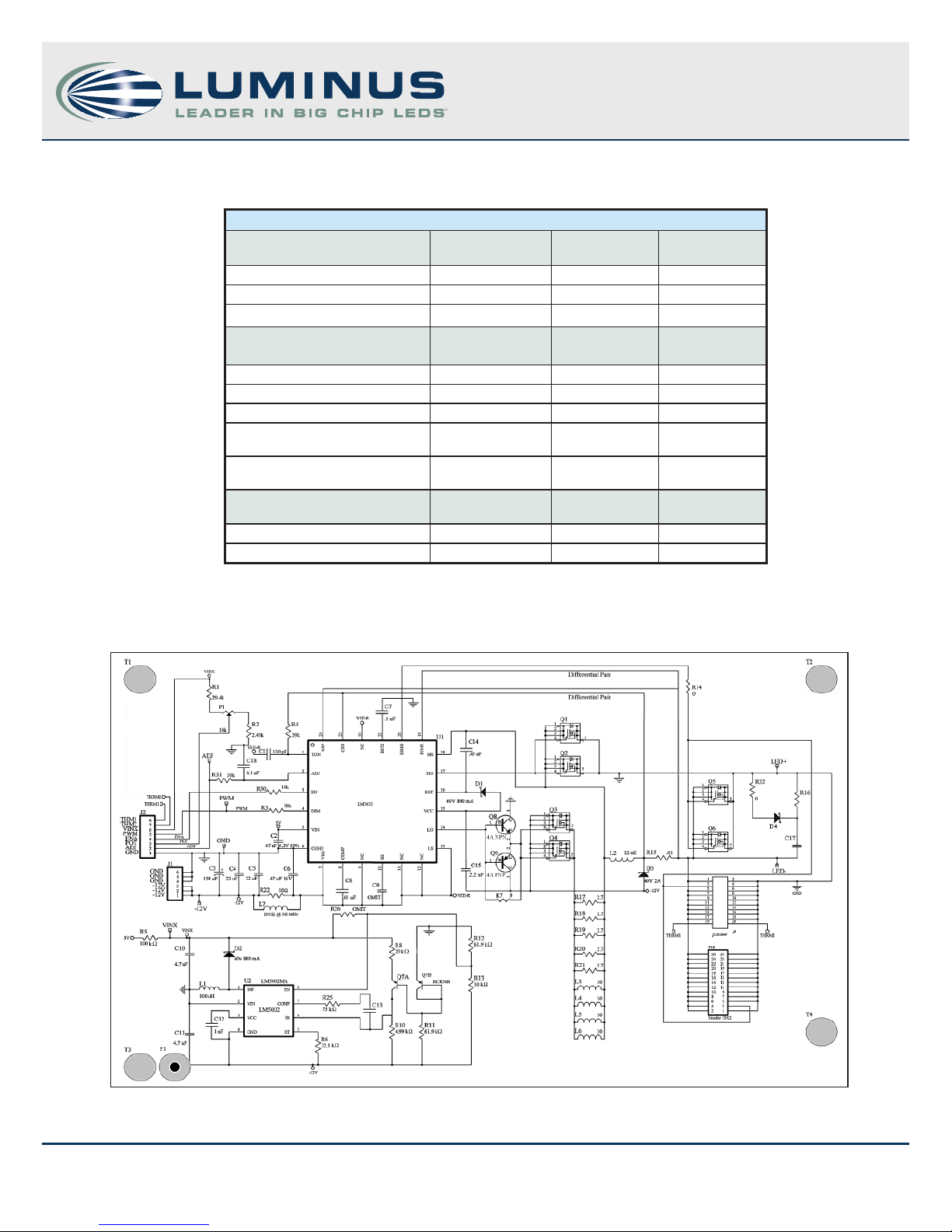
Appendix F: Driver Board Schematic and Pinout
11
960017 Rev C © 2013 Luminus Devices, Inc. - All Rights Reserved
Figure 15: Schematic of driver board
Luminus Devices, Inc. • T 978.528.8000 • www.luminus.com
1100 Technology Park Drive • Billerica, MA 01821
Page 12

Mouser Electronics
Authorized Distributor
Click to View Pricing, Inventory, Delivery & Lifecycle Information:
Luminus Devices:
DK-114N-1
 Loading...