

Page 1
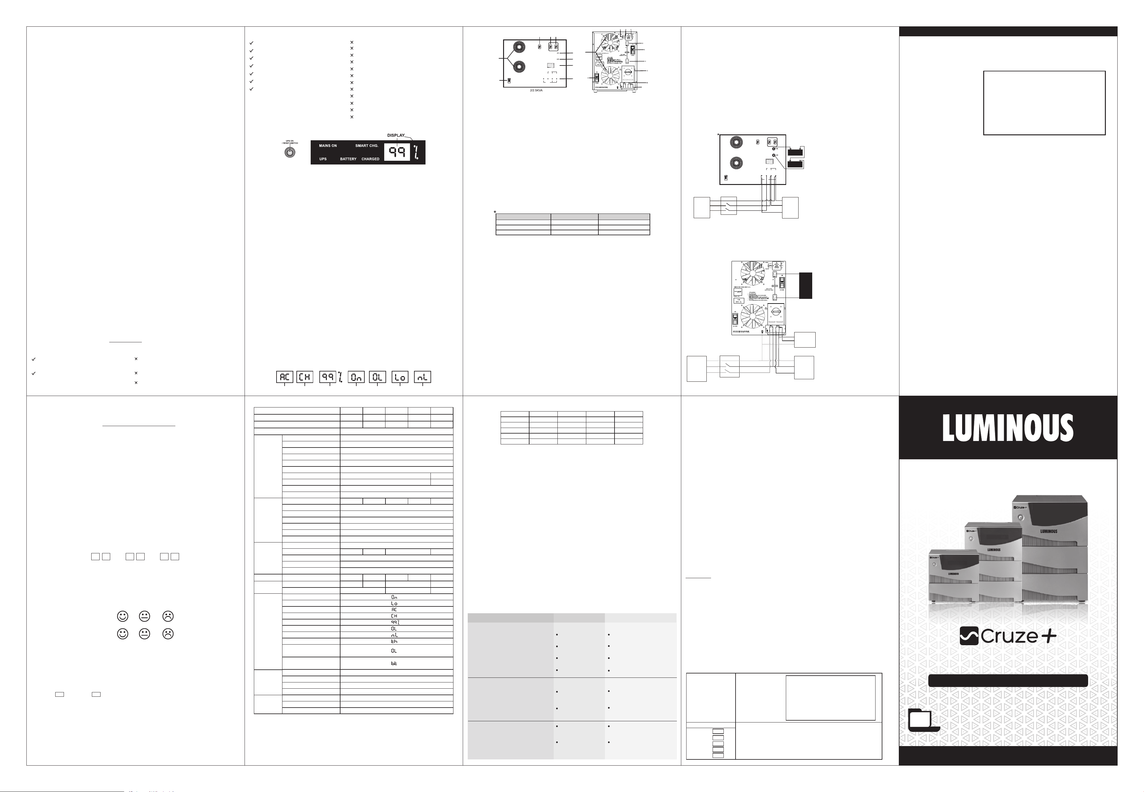
1. INTRODUCTION
1.1 Welcome to the ever-increasing family of satisfied LUMINOUS users. All LUMINOUS products like the
one you have just purchased, undergo a stringent quality check. This instrument provides clean and reliable
power to your Load and peripherals and protects them from blackouts, etc. The product is designed to provide
you an efficient performance with only minimal care and maintenance at your end. This manual will facilitate you
to not only understand the basic working of the UPS but will also facilitate the ease of its maintenance and use.
ywfeul ds lUrq’V rFkk fujUrj c<+us okys ifjokj esa vki dk Lokxr gSA ywfeul ds lHkh izksMDV~l dh DokfyVh tk¡p cM+h dq”yrk ls dh tkrh gSaA ;g ;wih,l
yskM rFkk ckgjh midj.kksa dks LoPN ,oa fo”oluh; ikoj iznku djrk gS vkSj mUgsa CySdvkmV gksus ls cpkrk gSA ywfeul ds izksMDV~l bl rjg ls fMtkbu
fd;s tkrs gSa rkfd ;g vkidks vPNh ijQkjesUl nsa rFkk bu dh ns[kHkky de ls de le; vkSj de ls de [kpsZ ls gks ldsA bl esuqvy ds }kjk vki dks bl
;wih,l ds izkjfEHkd dkedkt dks le>us vkSj bldh ns[kHkky djus esa lgwfy;r feysxhA
1.2 LUMINOUS CRUZE + SINE WAVE UPS provides backup power to fans, bulbs, computers etc. in the
event of power failure.
ywfeul Øwt Iyl lkbZu oso ;wih,l fctyh pys tkus ds ckn ia[ks] cYc] dEIk;wVj bR;kfn dks cSdvi ikoj iznku djrk gSA
1.3 Normally, the UPS operates on Mains, supplying power to the Load from the utility input. The battery
charger uses the Mains power to keep the battery at an optimal level. When the power fails, the UPS transfers
the load to the battery and converts the battery's DC power to AC power. The load operate normally until the
battery is exhausted. The load is automatically transferred back to the utility when the normal Mains gets
restored.
vkerkSj ij ;wih,l esUl ij dke djrs gq, yksM dks esUl ls ikoj iznku djrk gSA cSVjh pktZj cSVjh dks ,d mfpr Lrj ij j[kus ds fy, esUl ls ikoj ysrk
gSA fctyh pys tkus ij ;wih,l cSVjh ij dke djrs gq, yksM nsrk gS] tc rd cSVjh {kerk lekIr ugh gks tkrhA fctyh okil vkus ij yksM vius vki cSVjh
ls esUl ij Vªk¡lQj gks tkrk gSA
2. SAFETY GUIDELINES please go through these guidelines before connecting the UPS.
1.) Always connect the UPS to a two-pole, three-wire grounding Mains socket. The socket must be
connected to appropriately protected branch of the Mains (fuse/circuit breaker). Connection to any other type of
socket may result in a shock hazard.
;wih,l lnSo nks iksy rFkk rhu rkj xzkmafMax esaUl lkdsV ds lkFk tksfM+;sA lkdsV dks esUl dh mfpr lqjf{kr czk¡p ¼Q~;wt@lfdZV czsdj½ ds lkFk tksM+uk
pkfg,A fdlh vkSj izdkj ds lkdsV ls tksM+us ls fctyh dk >Vdk yxus dh laHkkouk jgrh gSA
2.) To Switch off the UPS output in an emergency, use the switch on front panel to switch the UPS off.
Disconnect the power cord from the Mains and remove atleast one battery connector.
vkikrdkyhu voLFkk esa ;wih,l dh vkmViqV cUn djus ds fy, lkeus okyk cVu cUn djsaA ikoj ds rkj dks esUl ls vyx dj nsaA cSVjh dk de ls de ,d
duSDVj vyx dj nsaA
3.) Avoid Installing the UPS in an excessively humid place or where there is water. Care must be taken to
ensure that the UPS is kept away from heat emitting appliances such as a heater, blower, oven etc. The unit
must also be placed in a manner that it avoids exposure to direct sunlight. The place of installation should be
well-ventilated and easily accessible for servicing.
;wih,l ,sls LFkku ij u j[ksa tgka ikuh gks ;k vR;f/kd ueh gksA bl ckr dk fo'ks"k /;ku j[kk tk, fd ;wih,l dks mu midj.kksa ls nwj j[kk tk, ftlls xeZ
rki fudyrh gS] tSls ghVj] Cyksvj vkSj vksou bR;kfnA ;wih,l dks ,sls LFkku ij ugha yxkuk pkfg, tgka lh/kh /kwi vkrh gksA ;wih,l j[kus dh txg goknkj
vkSj lfoZflax ds fy, ljyrk ls igqapus ;ksX; gksuh pkfg,A
4.) Foreign particles and water must not enter the UPS. Always ensure that no objects containing a liquid
are.) ever kept near the unit.
ckgjh dksbZ oLrq ;k ikuh ;wih,l ds vUnj ugha tkuk pkfg,A bl ckr dks /;ku j[kuk pkfg, fd xhyk ;k rjy inkFkZ ;wih,l ds ikl ugh j[kuk pkfg,A
5.) Don’t allow any spark near battery. Be sure not to come in contact with battery acid by any means.
cSVjh ds fudV dksbZ fpaxkjh u vkus nsaA cSVjh ds rstkc ls fdlh Hkh rjg ds lEiZd ls cpsA
6.) Place the battery compartment as near as possible to the UPS.
cSVªh dks ;wih,l ds ut+nhd gh yxk,saA
7.) Always switch off the UPS and disconnect mains when disconnecting the battery.
cSVªh dks gVkus ls igys esUl dks vo”; can djsaA
8.) Do not open the UPS there are dangerous high voltages inside even when power is off, contact the
company only if it is not working properly.
;wih,l dks Loa; uk [kksysa vkSj lgk;rk ds fy, lfoZl bathfu;j dh enn ysaA
9.) Replace the batteries and the fuse only with same rating and type.
cSVªh vkSj ¶;wt+ dks mlh jsfVax ds vkSj esd ls gh cnysaA
10.) TDR Output points are having 4min delayed operation, it’s recommended that these points should not be
touched after switching ON the UPS.
tc vkidk ;wih,l vkWu gks rc vki VhMhvkj vkmViqV ikWbaV~l dks u Nq, D;ksasfd ;g 4feuV ds varzky esa dke djuk “kq: djrk gSA
DO’S & DON’TS
Do’s related to UPS
Unplug and switch off the UPS before
touching or cleaning the surfaces.
Unplug the UPS from the wall outlet
during a lightening storm.
Don’ts related to UPS
Don’t block the side ventilation slots by cloth or other
material it may result in fire hazard.
Don’t place the UPS near radiation or heat source.
Don’t install the UPS near kitchen sink, laundry,
wash bowl, bath tub.
Do’s related to battery
Wear safety gloves and goggles.
Use battery grade water only for battery refilling.
Install battery in proper ventilated area.
Apply petroleum jelly to terminals of batteries.
Place battery horizontally & handle with care.
Keep out of reach of children.
Connect correct polarity of wires from UPS
with battery.
3. PHYSICAL DESCRIPTION:
3.1 The front panel display indicators & ON-OFF Switch
A) MAINS ON
Glows when the commercial mains is available with in normal limits (approx. 100-285V for 2-3.5-4KVA and
approx. 140-285V for 5.2KVA in Unregulated mode) as input to the unit.
;g pedrk gS tc def'kZ;y esUl ls fctyh ukWeZy fyfeV (vujsxqysVsM eksM esa approx. 100-285V 2-3.5-4KVA approx. ds fy, vkSj
140-285V 5.2KVA ) esa feyrh gSAds fy,
B) SMART CHG.
Monitors battery charge status & shall be ON/OFF as per the charge status of the battery. Smart Charge
indication turns OFF when the battery charging is about to be completed.
cSVjh ds pktZ dh voLFkk dh tkap djrk gSA bldk vkWu@vkWQ gksuk cSVjh ds pktZ dh voLFkk ij fuHkZj djrk gSA LekVZ pktZ bfUMds'ku cq> tkrh
gS tc cSVjh dh pkftZax iwjh gksus yxrh gSA
C) UPS ‘On’
Glows when the Mains is out of range and the UPS is running on battery.
;g pedrk gS tc fctyh ukeZy fyfeV esa ugha gS vkSj ;wih,l cSVjh ij dke djrk gSA
D) BATTERY ‘Lo’
Displays when UPS trips due to battery energy getting exhausted.
cSVjh dh {kerk [kRe gks tkus ds dkj.k tc ;wih,l fVªi gks tkrk gS] rc ;g pedrk gSA
E) UPS ‘OL’
Glows when the UPS is over-loaded in battery mode and it trips.
pedrk gS tc ;wih,l cSVjh eksM ij gks vkSj ml ij {kerk ls vf/kd yksM gks] lkFk gh cUn gks tkrk gSA
F) UPS ‘nL’
Displays when load connected to the output during battery mode is continuously less than 10% of VA rating
for more than 11 hours. The UPS will also shut down under this condition & can be restarted by switching
OFF & ON the UPS switch.
;g fn[krk gS tc vkmViqV yksM (cSVªh eksM dh fLFkfr essa) 10% VA jsfVax ls de gks vkSj yxkrkj 11 ?kaVs ls T;knk py pqdh gks rks ;wih,l can gks
tk,xkA bl voLFkk esa ;wih,l dks fLop vkWu vkSj vkWQ ls fjLVkVZ fd;k tk ldrk gSA
G) UPS ON / RESET SWITCH
This switches UPS ON/OFF. If the switch is Off the UPS will not work in the event of Mains failure. However
the charging will continue if Mains is in normal limit. This switch also works as a reset in an event of over load
and battery low shut down.
;g ;wih,l dks vkWu ,oa vkWQ djrk gSA ;fn ;g fLop vkWQ gS rks ;wih,l esUl Qsy dh voLFkk esa dke ugha djsxkA ;fn esUl lIykbZ vkWu gS rks
pkftaZx fujUrj gksrh jgsxh ;fn esUl lkekU; lhek esa gSA ;g fLop vkWu@vkWQ ds vykok vkWoj yksM vkSj cSVªh yks “kV~Mkmu ds fy;s jhlsV dk Hkh
dke djrk gSA
H) DISPLAY
During various conditions these symbols shall be visible on the display.
fHkUu&fHkUu voLFkk esa fMLIys ;g ladsr n'kkZrk gSA
MAINS ON
BATTERY CHARGED UPS ON OVER LOAD LOW BATTERY
CHARGING
Don’ts related to battery
Don’t add impure or mineral water in battery.
Don’t add acid to the battery as it can cause damage.
Don’t keep near a moisture area or in direct sunlight.
Don’t keep the cell caps loose or open.
Don’t increase the length of battery wire.
Don’t place the battery at height.
Never short the terminals of the battery.
Don’t over fill the battery cells.
Keep away flammable things to the battery.
Don’t dispose of batteries in fire.
Don’t open or mutilate batteries.
Don’t keep tools or metal parts on top of batteries.
NO LOAD
REGULATED UPS
UNREGULATED UPS
H G F
TUBULAR
BATTERY
SELECTION
FLAT PLATE
ON BY
INPUT
LINE OUT
LINE IN
LLN
OUTPUT
CHARGING
HIGH
MEDIUM
LOW
D
C
E
PASS
NEUTRAL
EARTH
B
E
Switch Selection
High
Medium
Low
K
J
Rating
2/2.5/3.5/4/5.2KVA
2/2.5/3.5/4/5.2KVA
2/2.5/3.5/4/5.2KVA
3.2 BACK PANEL
K
A
A. MINIATURE CIRCUIT BREAKER
This is connected at the input of the UPS and will trip in case of short-circuit or overload at output in Mains Mode.
;g ;wih,l dh buiqV ls tqM+k gSA esUl dh voLFkk esa vkmViqV ij “kkVZ lfdZV ;k vksojyksM gks tk, rks ;g fVªi gks tk,xkA
B. 4- WAY INPUT/OUTPUT TERMINAL BLOCK**
(i) This is used to connect commercial input AC supply (with correct wire polarity) to the UPS.(L-IN).
bldk iz;ksx esUl lIykbZ dks ¼rkjksa dh mfpr iksykfjVh½ ;wih,l ls tksM+us ds fy, gksrk gSA
(ii) This connector is provided for connecting the output (with correct wire polarity) of the UPS to the load.
(L-OUT)
;g dusDVj yksM dks ;wih,l ds vkmViqV ¼rkjksa dh mfpr iksykfjVh½ ls tksM+us ds fy, gksrk gSA
C. POSITIVE BATTERY LEAD
The positive end of the battery is connected to this lead.
cSVjh dk ikWftfVo fljk bl yhM ls tksM+us ds fy, gksrk gSA
D. NEGATIVE BATTERY LEAD
The negative end of the battery is connected to this lead.
cSVjh dk usxsfVo fljk bl yhM ls tksM+us ds fy, gksrk gSA
E. BYPASS SWITCH
In case of any fault in the UPS the Bypass switch bypass the UPS portion and allows the Mains to be available at
the output being independent of the battery.
;wih,l ds [kjkc gksus dh fLFfr esa ckbZikl fLop ikoj dks fcuk cSVjh ds Hkh vkmViqV ij ns ldrk gSA
F. BATTERY CHARGING SELECTION*
This Switch should be selected as per connected Battery capacity. This switch should be selected in High mode
when Battery capacity is 180Ah to 240 Ah, should be selected in Medium Mode when Battery Capacity is 150Ah
to 165 Ah & should be selected in Low mode when Battery Capacity is 120Ah to 135 Ah.
bl fLop dk p;u cSVjh dh {kerk ds vuqlkj djsA bl fLop dks gkbZ eksM esa j[ks tc cSVjh dh {kerk 180Ah ls 240Ah gks] fLop dks fefM;e eksM esa j[ks tc
cSVjh dh {kerk 150Ah ls 165 Ah gks vkSj bl fLop dks yks eksM esa j[ks tc cSVjh dh {kerk 120Ah ls 135Ah gksA
Battery Capacity
180~240 Ah
150~165 Ah
120~135 Ah
G. BATTERY SELECTION: This switch should be selected as per battery type.
(a) Switch Top Position: For TUBULAR BATTERY keep this switch in UP position.(Factory set)
¼d½ vxj cSVjh V~;qcyj gS rks fLop dks mPp fLFkfr esa j[ksaA ¼QSDVjh lsV½
(b) Switch Down Position: For FLAT PLATE BATTERY keep this switch in DOWN position.
¼[k½ vxj cSVjh ¶ySV IysV gks rks fLop dks fuEu fLFkfr esa j[ksaA
H. SWITCH
Regulated UPS Mode
Normally Switch should be kept in this mode while computer has to be run as this will ensure regulated voltage
input of 180V to 260V which is suitable for most of the computers. If the input voltage goes beyond this limit, UPS
will run on battery and will restore its operation in Mains mode on restoration of normal Mains.
jsxqysVsM ;wih,l eksM % lkekU;r fLop dks bl voLFkk esa j[kuk pkfg, tc dEI;wVj pykuk gks] D;ksafd ;g T;knkrj dEI;wVjksa dks 180V ls 260V fu;fer
buiqV oksYVst lqfuf”pr djrk gSA ;fn bl nkSjku buiqV oksYVst 180-260 ls de ;k T;knk gks tk,sxh rks ;wih,l cSVªh eksM ij pyuk “kq: dj nsxk vkSj tSls
gh esUl ukWeZy gks tk,sxh ;g esUl eksM esa okfil vk tk,sxkA
Unregulated UPS Mode
This mode can be used in case of computers having in built regulation mechanism or externally connected
automatic voltage regulator to take care of wide input voltage fluctuation of 100V to 285V for 2-3.5-4KVA and
140V to 285V for 5.2KVA.
vujsxqysVsM ;wih,l eksM % ;fn dEI;wVj esa vUr fufeZr jsxqys'ku eSdkfuT+e* ¼vius vki oksYVst dUVksZy flLVe½ mifLFkr gS ;k ckgjh vkWVksesfVd oksYVst
jsxqysVj ls tqM+k gS rks bl eksM ij dEI;wVj pyk;k tk ldrk gSA blls oksYVst&¶yDpw,'ku ¼100-285 oksYV 2-3.5-4KVA ds fy, vkSj 140-285 oksYV 5KVA
ds fy,½ rd dEI;wVj Bhd dke djsxkA
I. BATTERY MCB for will trip in case of battery reverse connection
cSVjh duSD”ku mYVk yxus dh fLFkfr esa cSVjh ,elhch fVªi gksxhA
J.TDR Output should be used for loads having high inrush current only. TDR will be available only for 4KVA &
5.2KVA models.
VhMhvkj vkmViqV dk iz;ksx gkbZ buj”k okys yksM ds fy, gh djsaA VhMhvkj dsoy 4KVA vkSj 5.2KVA ekWMy ds fy, miyC/k gksxkA
K. FAN
The assembly for fan.
ia[ks ds fy, vlsEcyhA
Note: DC MCB is also there on backside of 3.5KVA to 5.2KVA.
uksV% 3.5KVA ls 5.2KVA rd cSd iSuy ds ihNs Mhlh ,elhch Hkh gSA
4. UNPACKING & PLACEMENT
1. Unpacking: On receiving the UPS, inspect for any transit damage. The packaging can be saved for future use.
;wih,l dks ysrs le; bl ckr dks lqfuf'pr dj ys fd ;wih,l {kfrxzLr rks ugh gSA iSfdax dks Hkfo"; esa mi;ksx ds fy, laHkky ds j[ksA
2. Placement: UPS shall be kept at a place which is protected from dust, water, temperature and humidity.
;wih,l dks ,sls txg ij yxk,sa tks /kwy] ikuh] rki vkSj vknzZrk ls lqjf{kr gksA
5. INSTALLATION DIAGRAMS
1). BATTERY INSTALLATION
CAUTION: Battery polarity must be checked before connections. Wrong polarity connection with UPS
will cause Reverse Protection Fuse Blown and may lead to Fire Hazards.
Installation shall be done by qualified technician.
• Take precautions while connecting the battery cable to the battery post, avoid short circuit by spanner etc.
• Battery terminals and thimble etc., should be cleaned and properly fastened otherwise it may give false
indications of battery charged and low battery trips.
2). CONNECTION DIAGRAM OF UPS WITH MAINS & BATTERY
TUBULAR
BATTERY
SELECTION
FLAT PLATE
ON BY
LINE OUT
LINE IN
LLN
OUTPUT
CHARGING
HIGH
MEDIUM
LOW
BATTERY
PASS
INPUT
NEUTRAL
EARTH
E
BATTERY
E
N
Load
L
Electricity
Board
Meter
E
N
L
Double-Pole
Switch Lighting
Circuit
REGULATED UPS
UNREGULATED UPS
*Connection dig. is for 2KVA. No’s of batteries to be connected in series should be
as per UPS rating (models).
Note: UPS should be connected with 32A Class C MCB at building distribution wiring for 2KVA model.
uksV % 2KVA ekWMy ds fy, 32A Dykl lh ,elhch dks fcfYMax fMfLVªC;q”ku ok;fjax ls tqM+k gksuk pkfg,A
AS per
System
DC BUS
Rating
“TDR Connection Procedure”
High inrush current load should be connected at
TDR Points as per connection dig.. An additional
with TDR
delay of 4min in power ON will be there in connected
loads with TDR.
Load
“Applicable for 4KVA, 5.2KVA models only”
Electricity
Board
Meter
E
N
L
Double-Po le
Switch Lighting
Circuit
N
Load Connected
L
E
E
N
L
TH IS PO RTI ON TO BE FI LLE D BY T HE DE AL ER
PRODUCT DETAILS: ABOUT THE UPS
MODEL:
SERIAL No. :
ABOUT THE BATTERY
Battery Model & Capacity:.....................................................................................................................
Battery Serial No.1:................................................................................................................................
Battery Serial No.2:................................................................................................................................
Battery Serial No.3:................................................................................................................................
Battery Serial No.4:................................................................................................................................
DATE OF INSTALLATION:
Signature of Installation Personnel
DEALER DETAILS
(Please fill / affix. your stamp)
Name .....................................................................................................................................................
Address...................................................................................................................................................
................................................................................................................................................................
City : ....................................................... State : ...................................................................................
Contact No. /Res./Off. ...........................................................................................................................
E-mail : .................................................................................................................................................
Dealer Signature & Date
WARRANTY REGISTRATION FORM
CUSTOMER DETAILS
Name: ........................................................................................................................................................
Address: ...................................................................................................................................................
...................................................................................................................................................................
...................................................................................................................................................................
City: ...................................................... State: .........................................................................................
Pin: ........................................ Contact No.:Res./Off. ...............................................................................
Occupation: ...............................................................................................................................................
Birthday (optional) :
D D M M Y Y
How did you first hear about our product : ...............................................................................................
• Please rate how you felt ? (please circle appropriate option)
During the sales presentation
At the time of installation
The Product has been installed to my satisfaction. (Please refer to the Installation Procedure and
safety measures outlined in accompanying guide for users) :
Yes No
Customer Signature & Date
10. SPECIFICATIONS
Ratings
Apparent Power
Active Power
2KVA
#
2000VA
1680W
2.5KVA
2500VA
2100W
3.5KVA 5.2KVA
3500VA
2940W
Regulated UPS mode
Input
Output
Battery
*TDR
Physical
Rated voltage
Undervoltage
Undervoltage Restoration
Overvoltage
Overvoltage Restoration
Unregulated UPS mode
Undervoltage
Undervoltage Restoration
Overvoltage
Overvoltage Restoration
Maximum Power
Rated voltage (UPS Mode)
Voltage (Mains Mode)
Frequency (UPS Mode)
Frequency (Mains Mode)
Overload
Transfer Time(typical a.s.)
Capacity*
Number
Typical Recharge Time
Battery Boost Voltage
Protection
TDR Delay
Net weight (Kg.)
Dimension (LxWxH)(mm)
2KVA
2.5KVA
SAME AS INPUT (45-55 Hz)
120Ah-240Ah LEAD ACID TYPE/TUBULAR
2
LOW BATTERY, REVERSE POLARITY
22.25
280x305x280
220V AC
180±5V
185±5V
260±5V
255±5V
100±10V
115±10V
285±10V
270±10V
3.5KVA
220V AC
SAME AS INPUT
50±0.5Hz
> 110%
20 ms.
3/4
10-12 Hrs.
14.2V - 14.6V (±0.2V)
NA NANA
23.00
280x305x380
UPS On
Battery Low
Mains On
Smart Charge
Battery Charged
Digital
Displays
Overload
No Load
Overtemperature
Short circuit under
battery mode
MCB Trip or Short Circuit
under Mains mode
Low Battery Pre-alarm
Low Battery
Alarms
Overload
No Load Shutdown
Environmental
Due to continuous product improvement, the specifications are subject to change without notice.
* TDR ON Time ~4Min. and it can add additional 4 Min delay in AC startup during power failure.
* Recommended AC rating upto: 1.5 Ton, 3Star rated.
*AC (Air Conditioner) Operating Mode :
Unit works fine in Eco/UPS Mode for Inverter AC or Normal AC with stabilizer.
For Normal AC without stabilizer unit to be used in UPS Mode only.
#
Active Power is defined in Mains Mode for Linear Load.
Operating Temperature
Storage Temperature
Humidity
ONE BEEP EVERY 10 SECONDS
CONTINUOUS BEEP FOR 10 SEC.
CONTINUOUS BEEP FOR 10 SEC.
CONTINUOUS BEEP FOR 10 SEC.
0-45°C (32-113°F)
0-45°C (32-113°F)
0-95% RH non-condensing
4KVA
4000VA
3360W
4KVA
4
4Min approx 4Min approx
31.90
280x365x380
(Steady)
(Blinking)
5200VA
4368W
140±5V
150±5V
5.2KVA
6
44.50
** Recommended Wire Gauge & MCB for Input Output Wiring.
WIRE GAUGE
2KVA
2.5KVA
3.5KVA
4KVA
5.2KVA
INPUT
2.5mm²
2.5mm² 1.5mm² 2.5mm²
4mm² 2.5mm² 4mm²
4mm²
6mm²
OUTPUT OUTPUT MCBEARTHING
1.5mm²
2.5mm²
4mm²
2.5mm²
4mm²
6mm²
10Amp
16Amp
25Amp
25Amp
32Amp
6. STEPS FOR UPS INSTALLATION:
• To be done by a competent & knowledgeable person.
• Switch OFF the supply to the distribution point to which the UPS is to be connected.
• Check the building wiring. Improper building wiring could result in equipment damage that is not covered in
warranty.
• Connect the battery/batteries to UPS as per its correct polarity.
• Keep the front switch of UPS on OFF position.
• Switch ON the front switch & measures the output voltage on output terminal block, if it is as per specification
then switch off the UPS.
• Connect the Load wire to the output terminal block located on the rear panel of UPS.
• Switch ON the front Switch of the UPS.
• Gradually put the load on UPS.
• Connect input plug to input terminal block located on the rear panel of UPS in correct polarity .
;wih,l yxkus ds rjhds%
• baLVkys”ku n{k bathfu;j }kjk gh djk tkuk pkfg,A
• ;wih,l dh esUl lIykbZ dks can dj nsaA
• ok;fjax dh lgh ls tkap dj ysa] xyr ok;fjax ;wih,l dh dk;Z{kerk ij vlj Mky ldrh gSA
• cSVªh dks ;wih,l ds lkFk djSDV iksysfjVh esa tksM+sA
• ;wih,l dks fLop vkWQ dh fLFkfr esa gh j[ksa cSVªh duSDV djus ds ckn fLop vkWu djsa vkSj vkmViqV oksyVst+ eki ysa] ;fn ;g funsZf”kr jsat esa gS rks fLop vkWQ
dj nsaA
• vkmViqV ds rkjksa dks vkmViqV VfeZuy esa Mkysa vkSj yksM vkWu djsaA
• esUl buiqV ds Iyx dks lgh iksysfjVh esa buiqV iWkbaV esa duSDV djsaA
7. TROUBLESHOOTING
PROBLEM
A. The mains supply is normal but...
a) The MAINS ON indicator is off. The UPS is
either working on battery (UPS ON indicator is
glowing) or battery has exhausted (BATT.LOW
is glowing).
b) Display shows ‘bt’.
B. In the battery mode all indicators are off
but...
a). The BATT.LOW indicator glows.
b).
Display shows ‘th’.
C.a). In the battery mode all indicators are off
but the UPS ‘OL’ display is constant.
b). In the battery mode all indicators are off
but ‘OL’ display is blinking.
POSSIBLE
CAUSE(S)
Line cord plug is loose.
Dead wall socket.
Mains input voltage too
low and too high.
The MCB is trip
The battery may have
got discharged from
recent use.
The UPS has tripped
due to overheating
condition.
The UPS has tripped
due to overload
condition.
The UPS is tripped due
to short circuit.
Fit the line cord plug properly.
Check the socket with any lamp etc.
Wait for mains to normalize.
Reset the MCB.
Recharge the battery after Mains
restoration.
Call for authorised technician.
Reduce the load and turn the
reset switch (on the front panel)
on/off.
Switch off all loads and then turn
on load one by one and if ‘OL’
blinking display takes place again,
call for authorised technician.
ACTION
RECOMMENDED
8. WARRANTY
LUMINOUS POWER TECHNOLOGIES PVT. LTD. warrants it’s UPS to be free from defects in materials and
workmanship for a period of two year after initial delivery. This obligation is limited to servicing any Long Backup
UPS or part returned to the authorised service centre for that purpose and to making good any parts thereof
which shall, within the warranty period, be returned to the Company or Authorised Service Centre under a written
intimation and which to the company's satisfaction be found defective. The company reserves the right to decide
as to whether the repair work should be carried out in the company's service center or at site or at any other
place. The freight incurred for to and fro despatch of the defective material will have to be borne by the customer,
and the transit risk for the material will rest with the purchaser.
The warranty does not extend to any parts of the instrument which have been subjected to misuse or accident.
Further, this warranty does not extend to any instrument which has been tampered with by any agency not
authorised by the company.
The warranty will last for a period of 24 months from the date of initial delivery / despatch of the instrument if used
within its specifications. The warranty for the replaced components will lapse along with that of the main
instrument. LUMINOUS POWER TECHNOLOGIES PVT. LTD. reserves the right to make changes in design
and specifications without notice and without any obligation to install such changes on units previously supplied.
In no event will LUMINOUS POWER TECHNOLOGIES PVT. LTD. , its Distributors / Dealers be liable for
consequential or incidental damages or for any expenses incurred by the buyer or user, due to use or sale of
products sold by LUMINOUS POWER TECHNOLOGIES PVT. LTD. directly or through its authorised
Distributors / Dealers or any third party.
Until superseded otherwise or in contractual form this warranty is made expressly in lieu of all other liabilities and
obligations on part of LUMINOUS POWER TECHNOLOGIES PVT. LTD. .
Title to the instrument passes to the buyer upon delivery to the common carrier.
IMPORTANT
In the event of an instrument requiring servicing at our authorised service center, the following procedure should
be adopted.
1. The instrument must be securely packed, preferably in its original packing.
2. The instrument should be despatched on Freight-prepaid basis duly insured.
3. One of our Service/ Sales Executives should be informed of the Goods Receipt No. and date of despatch
along with the name of the carrier.
4. The above procedure should only be adopted on the advise of one of our Service/Sales Executive or Dealer.
5. We reserve the right to charge the consignee for any damage incurred during transit.
9. SERVICE
In the unlikely event if you are facing a problem that has not been sorted out by troubleshooting, kindly adopt the
following procedure: Complaints may be logged on our 24-hour service call-desk number 1860 500 3939 or
1800 103 3039.
;fn vkidh leL;k,¡ vkdfLed] leL;kvksa esa fy[ks rjhds ls ugha lqy>rh rks vki gekjs 24-hour service call-desk number 1860 500 3939 ;k
1800 103 3039 ij lEidZ djsaA
EQUIPMENT DETAILS
MODEL : Cruze +
Sr. No. :
RATING
2KVA
2.5KVA
3.5KVA
4KVA
5.2KVA
24
MONTHS
WARRANTY
PRN-MN-206-02
UPS
2kVA/2.5kVA/3.5kVA/4kVA/5.2kVA
User Manual
 Loading...