

Page 1
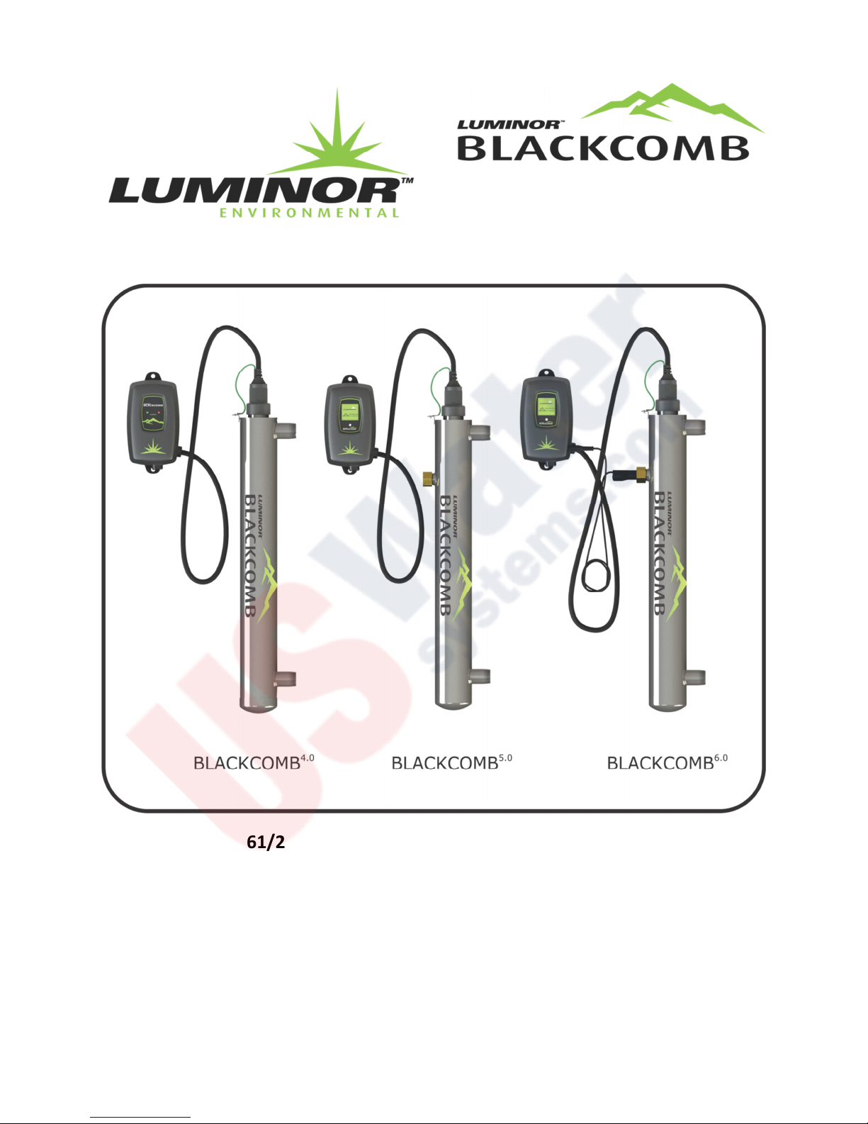
OWNERS MANUAL
Operation & Installation Instructions
LB4-031/2, LB4-061/2, LB4-101/2, LB4-201/2, LB5-031/2, LB5-061/2, LB5-101/2,
LB5-201/2, LB6-061/2, LB6-101/2, LB6-201/2
illuminating technologies for life
Page 2

Congratulations on purchasing this ultraviolet disinfection system. By purchasing a LUMINOR UV
Disinfection system you are receiving not only a high quality product but also peace of mind. Protecting
your water supply with a UV system gives you reassurance that your family will have access to safe
drinking water throughout your entire home with no chance of microbiological contamination. This is
chemical free process which is simple in its concept and effective in its abilities to inactivate
microorganisms present in the water supply. Simple maintenance, continuous disinfection and
ultimately safe water, LUMINOR makes it that easy.
Page 3

TABLE OF CONTENTS
Safety Considerations ............................................................................................................................ Page 4
Before You Begin ................................................................................................................................... Page 4
Water Quality Parameters ..................................................................................................................... Page 4
Assembly ................................................................................................................................................ Page 5
System Sizing ......................................................................................................................................... Page 6
Location ................................................................................................................................................. Page 6
Installation ............................................................................................................................................. Page 6
System Disinfection ............................................................................................................................... Page 10
System Disinfection ............................................................................................................................... Page 10
Cleaning (quartz sleeve & UV sensor ..................................................................................................... Page 11
Operation (4.0 Controller Overview) ..................................................................................................... Page 12
Operation (5.0 & 6.0 Controller Overview) ........................................................................................... Page 13
Operation (5.0 & 6.0 Power-up) ............................................................................................................ Page 13
Operation (5.0 Controller Screens) ........................................................................................................ Page 14
Operation (6.0 Controller Screens) ........................................................................................................ Page 15
Operation (5.0 & 6.0 UV Intensity) ........................................................................................................ Page 15
Operation (5.0 & 6.0 Lamp Countdown) ............................................................................................... Page 16
Operation (5.0 & 6.0 Lamp Countdown Reset) ..................................................................................... Page 16
Operation (5.0 & 6.0 Failure Modes) ..................................................................................................... Page 17
Operation (5.0 & 6.0 QR Codes) ............................................................................................................ Page 18
Expansion Modules ................................................................................................................................ Page 18
Warranty Registration ........................................................................................................................... Page 20
4.0
BLACKCOMB
BLACKCOMB
BLACKCOMB
Specifications ................................................................................................................ Page 21
5.0
Specifications ................................................................................................................ Page 22
6.0
Specifications ................................................................................................................ Page 23
Limited Warranty Statement ................................................................................................................. Page 24
3 | P a g e
Page 4

Safety Consideration:
Although your UV system has been manufactured to the highest safety standards, extreme care must be followed
when operating and/or maintaining your system.
1. Whenever you are servicing this equipment, always disconnect the power cord from the electrical outlet.
2. As the energy given off by the UV lamp can be harmful to your eyes and skin, NEVER look directly at an
illuminated UV lamp without adequate eye protection and always protect your skin from direct exposure
to the UV light.
3. To ensure the system provides adequate disinfection, ALWAYS replace any component (lamp and sleeve)
with a genuine manufacturer’s replacement part.
4. Do not operate the unit if it has any damaged or missing components.
5. To avoid possible electrical shock, use only with a properly grounded electrical outlet.
6. Never perform any maintenance to the system unless you are comfortable in doing so. Contact the
manufacturer for service instructions if required.
7. Do not use this system for any purpose other than what it was intended for. Misuse of this system could
potentially cause harm to the user.
8. Your system is intended to be installed indoors and away from leaking plumbing. DO NOT plug the unit in
if the system or any of the components are wet.
9. The disinfection system should be directly installed into a ground fault circuit interrupter (GFCI). If the use
of an extension cord is required, the cord must be manufactured with a minimum of 16 gauge wire and
care should be taken to avoid potential tripping hazards.
10. We recommend that a licensed plumber or certified technician perform the installation
Before You Begin:
Before you begin, you’ll need the following:
Tools
• Pipe cutter, hacksaw or other specialized tools required to cut into your existing plumbing (e.g. if you have
PEX piping)
• Soldering tools (torch, flux, emery cloth and solder)
• Wrench (for tightening fittings)
Other Materials
• Inlet/outlet connections
• Teflon™ tape
Water Quality Parameters:
UV disinfection is extremely effective against microorganisms but only if the UV light can pass through the water it
needs to treat. This means that the quality of your water is very important in order to ensure complete
disinfection.
It is imperative that you have your water tested for at the least the parameters listed below. If the water exceeds
the listed parameters LUMINOR strongly recommends that appropriate pretreatment equipment be installed
(pretreatment will depend on parameters being treated):
4 | P a g e
Page 5
Hardness: <7 gpg (120 mg/L) – if hardness level is 7 gpg or slightly below the quartz
sleeve must be cleaned periodically in order to ensure efficient UV
penetration; if above the water must be softened
Iron (Fe): <0.3 ppm (0.3 mg/L)
Manganese (Mn): <0.05 ppm (0.05 mg/L)
Turbidity: < 1 NTU
Tannins (organics): <0.1 ppm (0.1 mg/L)
UVT (transmittance): >85% (Please contact LUMINOR if water has a UVT that is less than 80% for
pre-treatment recommendations)
You can have your water tested at a private analytical laboratory or by your local dealer. It is always
recommended to install pre-filtration of at least 5 microns prior to a LUMINOR UV disinfection system.
Assembly:
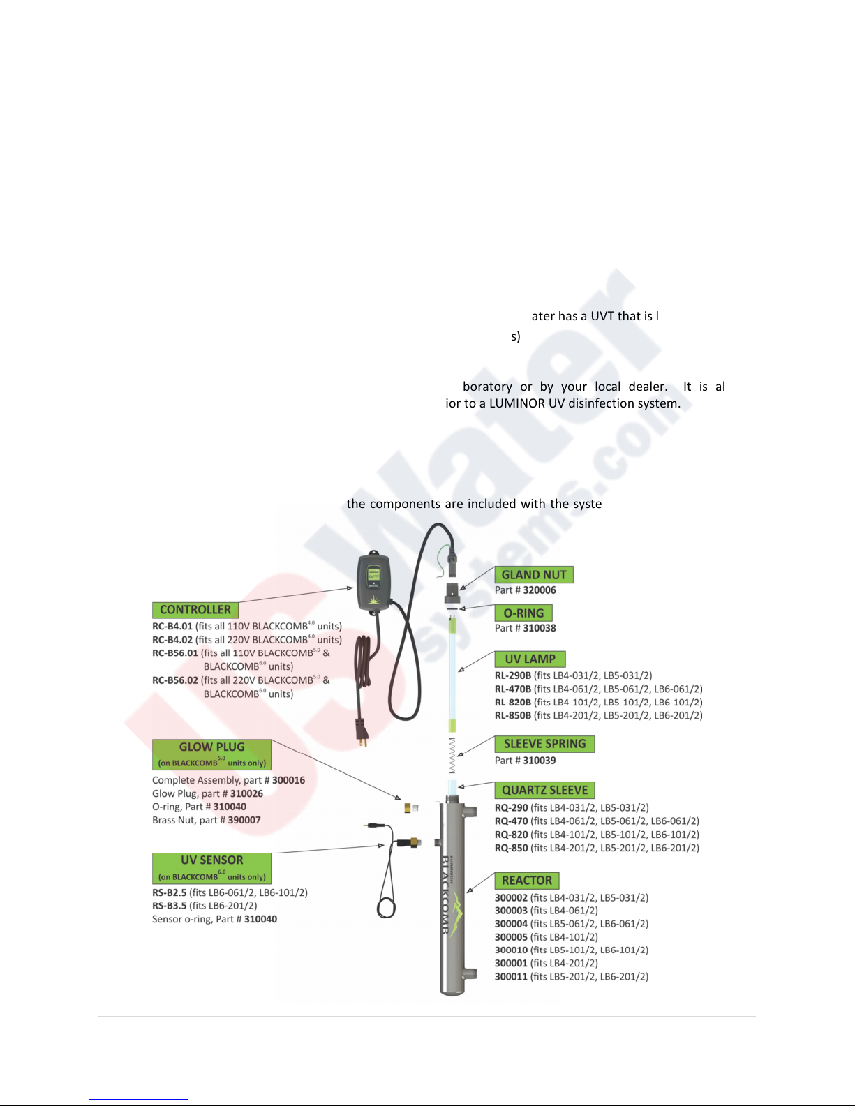
Step 1: Unpack the system and ensure all the components are included with the system. Your system is shipped
with the following components:
5 | P a g e
Page 6
System Sizing:
All LUMINOR UV systems are rated for a specific flow rate under specific water quality parameters. The equipment
has been designed to ensure that the appropriate dose will be delivered provided all parameters are followed.
PLEASE NOTE that the flow rate for each system can be higher or lower than what the system is rated for however
this will change the dose level that the system will deliver. A lower flow is not a concern as the dose will increase
however a higher flow rate will decrease the dose and therefore compromise the microorganism inactivation.
It is important to know the maximum flow rate that your water system delivers. If you do not have this
information you can simply fill a 1 gallon bucket with water and time how long it takes to fill up. This will be the
maximum flow rate for the home. Choose a BLACKCOMB system that is suitable.
PLEASE NOTE: It is always better to oversize your system then to undersize. For example, if your pump delivers 8
gpm it is recommended to install any of the BLACKCOMB 10 gpm systems. There will come a time where your
home is using water at the pump’s maximum capacity.
Location:
Step 1: Find a suitable location to mount the UV
reactor and the accompanying controller. In
choosing your location ensure the controller is
located within 5 feet of a ground fault circuit
interrupter (GFCI) and that there is easy access
to the main cold water line prior to any branch
lines and before the hot water heater. If you
have any other water treatment equipment,
such as a softener or water filter, ensure that
the UV is the last piece of treatment equipment.
PLEASE NOTE: All LUMINOR UV disinfection
systems are intended for indoor use only as they
should not be exposed to the elements.
Step 2: Your system includes mounting
hardware for both the UV reactor and the
controller. If the supplied fasteners are not
compatible with the structure in which you are
mounting the device, please ensure you use the
correct fasteners.
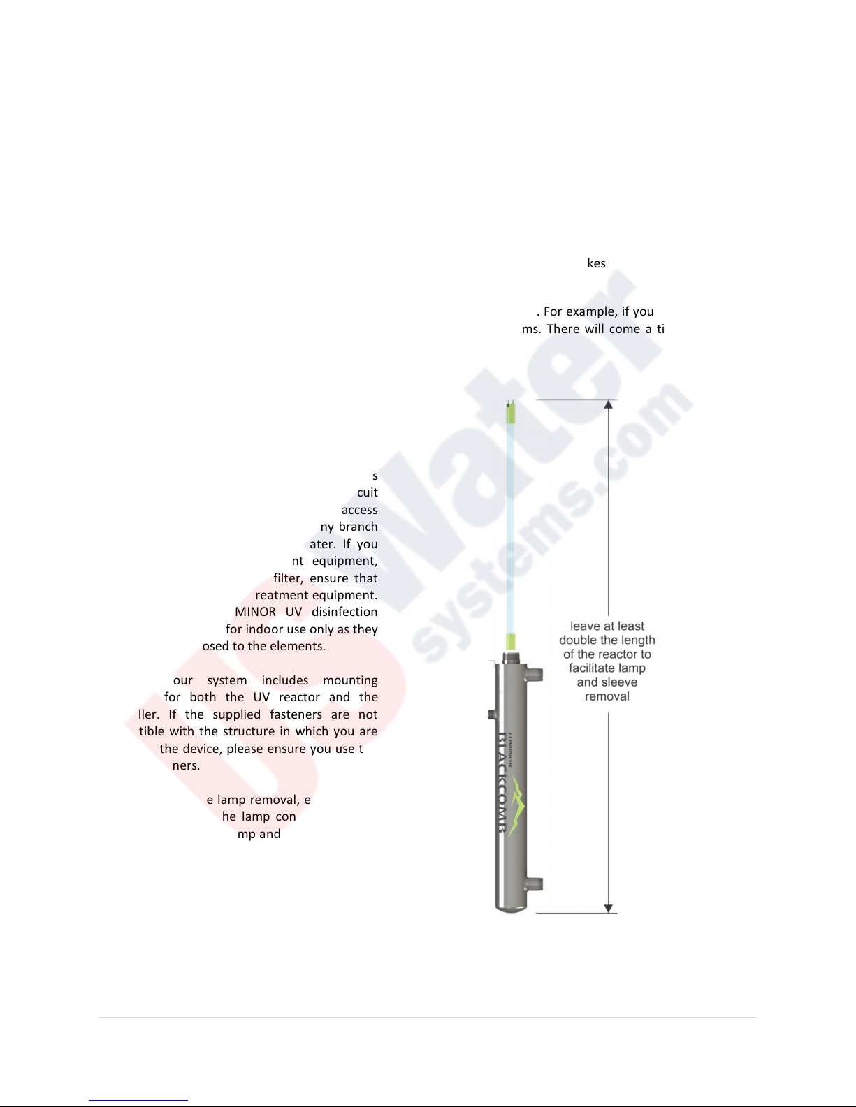
Step 3: To facilitate lamp removal, ensure there
is enough space at the lamp connector end to
safely remove the UV lamp and/or quartz sleeve
(a space equal to the length of the unit will
suffice) (see Figure 1.).
Figure 1. Lamp Removal Spacing
6 | P a g e
Page 7
Installation:
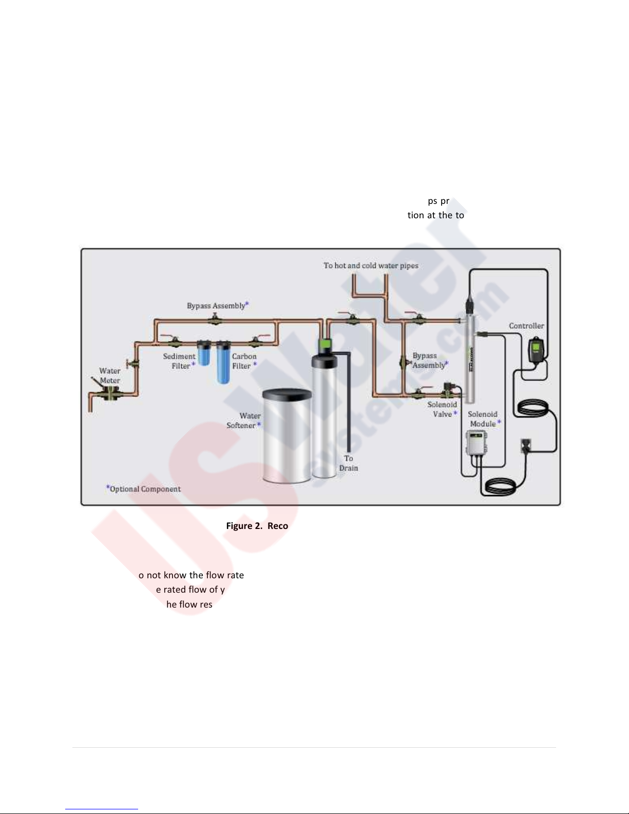
Step 1: The UV disinfection system should always be the last piece of treatment before the water branches off to
the hot and cold water lines if the intent is for Point of Entry (POE) (see figure 2). If the intent for the UV system is
for Point of Use (POU) the system should be the final step before the faucet.
Step 2: LUMINOR strongly recommends that a 5 micron filter be installed before the UV system for a final polishing
step before the water is disinfected.
Step 3: The reactor can be installed either horizontally or vertically using the clamps provided, however vertical
installation is the preferred method with the inlet at the bottom (lamp connection at the top) as it allows any air
that may be in the lines to be easily purged from the system.
Figure 2. Recommended POE Installation
Step 4: If you do not know the flow rate of the water supply in your home it is recommended that you use a flow
restrictor so that the rated flow of your particular LUMINOR BLACKCOMB system is not exceeded and the UV dose
is not compromised. The flow restrictor should be installed on the outlet port of the reactor.
Step 5: It is strongly recommended to have a licensed plumber connect the UV reactor to the water supply and
may be a requirement depending on where you are located. If you are attempting this yourself, ensure you have
all the necessary tools and fittings to accomplish this task.
Step 6: Although there are many methods of installation, this manual will provide a recommended procedure using
copper plumbing and standard soldering methods. LUMINOR recommends the use of unions, a by-pass assembly
and shut-off valves as this will allow you to isolate and remove the UV reactor if necessary (this method is a
7 | P a g e
Page 8
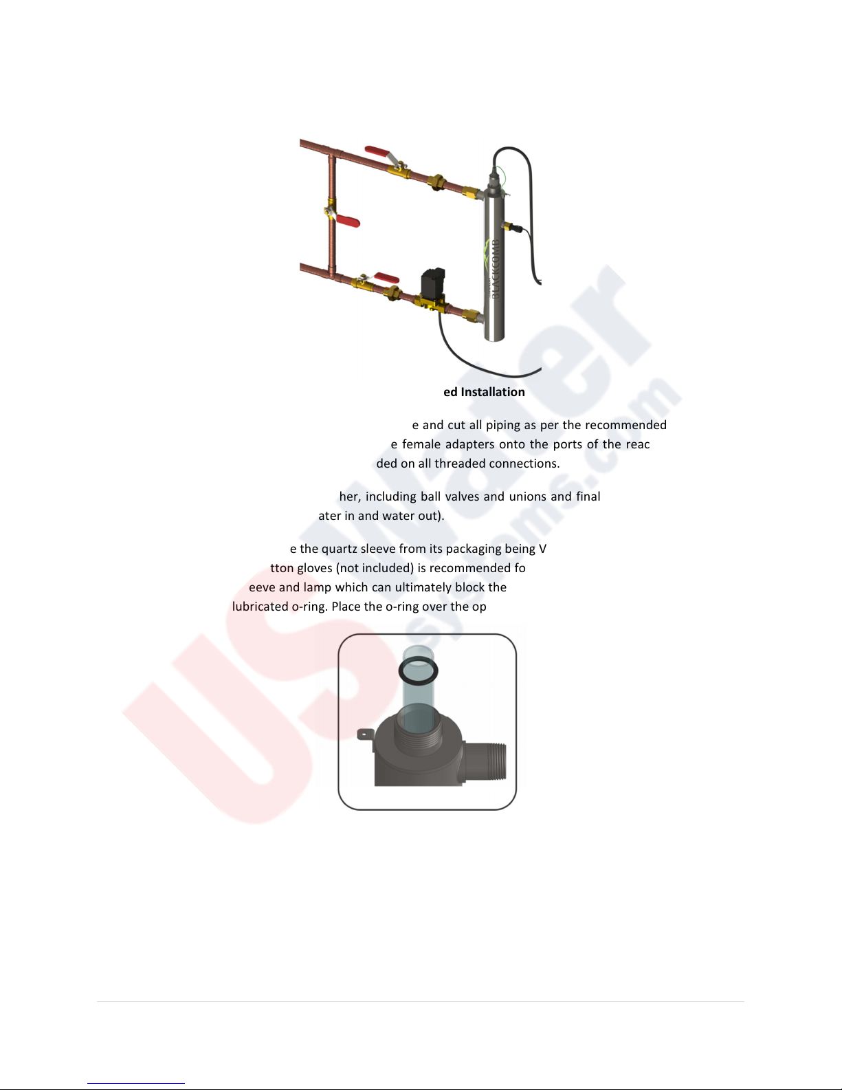
recommended method only however it allows for the maximum convenience but it requires extra components and
more time for installation. Please refer to Figure 3 for the recommended installation.
Figure 3. Recommended Installation
Step 7: Before you cut into the cold water line, measure and cut all piping as per the recommended layout. Once
all the components are ready, start by installing the female adapters onto the ports of the reactor. To ensure a
proper seal, the use of Teflon™ tape is recommended on all threaded connections.
Step 8: Next solder all the assembly together, including ball valves and unions and finally connected the by-pass
assembly to the cold water feed line (water in and water out).
Step 9: You can now gently remove the quartz sleeve from its packaging being VERY careful not to touch the length
with your hands. The use of cotton gloves (not included) is recommended for this procedure as oils from our hands
can leave residue on the sleeve and lamp which can ultimately block the UV light from getting to the water. In the
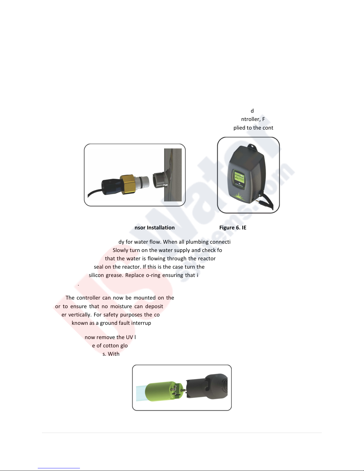
package, you will find a lubricated o-ring. Place the o-ring over the open-end of the sleeve as shown in Figure 4.
Figure 4. Quartz Sleeve Installation
Step 10: Carefully slide the sleeve into the reactor until you can feel it hit the opposite end of the reactor. Slightly
push the sleeve in to feel it lock into the spring inside the reactor. Ensure that the o-ring is butted up against the
reactor. Assemble the provided gland nut onto the threaded end of the reactor and tighten. The gland nut has a
positive stop to avoid over-tightening, hand tighten ONLY. Install the provided stainless steel compression spring
inside the quartz sleeve. This spring simply sits in the bottom of the quartz sleeve and works with the lamp and
8 | P a g e
Page 9
LUMI-Loc™ connector to create the proper lamp alignment. PLEASE NOTE: DO NOT install a UV lamp inside the
quartz sleeve without the sleeve spring in place.
Step 11: (Applies only if you have a UV sensor…BLACKCOMB
6.0
) The UV sensor for the system is packaged in a
separate plastic bag. Carefully remove the sensor from its packaging and insert the sensor into the UV sensor port
(remove the protective cap on the UV reactor first). The sensor can only go in one way. Ensure that the flat portion
of the UV sensor matches up with the half metal lip on the sensor port (flat portion should face the lamp
connection end) (see Figure 5.). Ensure that the sensor is fully seated in the sensor port and then tighten (turning
clockwise) the sensor nut. PLEASE NOTE: DO NOT over tighten the nut as this could damage the Teflon sensor
body. Plug the male connector into the IEP port located on the right side of the controller, Figure 6, (make sure the
controller is not plugged in as the sensor MUST be attached before power is applied to the controller.)
Figure 5. UV Sensor Installation Figure 6. IEP Connection
Step 12: The reactor is now ready for water flow. When all plumbing connections have been completed you should
check for any possible leaks. Slowly turn on the water supply and check for leaks. Make sure the by-pass valves are
functioning properly and that the water is flowing through the reactor. The most common leak is from the o-ring
not making a proper seal on the reactor. If this is the case turn the water off, drain the reactor, remove the o-ring,
dry it and reapply silicon grease. Replace o-ring ensuring that it is properly sealed against the reactor and check
again for leaks.
Step 13: The controller can now be mounted on the wall. The controller should always be above or beside the
reactor to ensure that no moisture can deposit on any of the connections (see Figure 2.). Always mount the
controller vertically. For safety purposes the controller should be connected to a ground fault circuit interrupter
(GFCI) (also known as a ground fault interrupter (GFI)).
Step 14: You can now remove the UV lamp from its packaging being careful not to touch the lamp quartz with your
hands. Again, the use of cotton gloves is recommended to avoid deposited oils on the lamp glass. Always hold the
lamp by the ceramic ends. With the lamp outside of the reactor, affix the UV lamp to the lamp connector as shown
in Figure 7.
Figure 7. UV Lamp Connection
9 | P a g e
Page 10
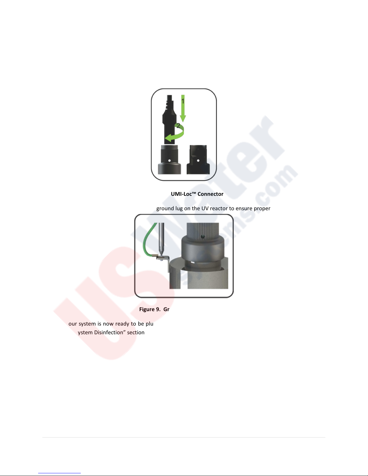
Step 15: Carefully insert the UV lamp into the reactor sliding it inside the quartz sleeve located inside the reactor
(do not drop the lamp into the reactor). Affix the LUMI-Loc™ connector into the gland nut by inserting the
connector into the nut and turning the connector approximately ¼ turn to lock the connector to the gland nut.
Figure 8. LUMI-Loc™ Connector
Step 16: Affix the captive ground screw to the ground lug on the UV reactor to ensure proper grounding continuity.
Figure 9. Ground Screw Connection
Step 17: Your system is now ready to be plugged into the appropriate GFCI protected outlet. Plug the unit in and
refer to the “System Disinfection” section before any water is allowed to flow through the system.
System Disinfection:
Now that the system is installed you will need to disinfect the lines throughout the entire home or facility. To
accomplish this, please follow these simple steps:
Step 1: Before performing this task, check to make sure that there are no “dead ends” in the lines throughout the
home as these can harbor bacteria. Also ensure that the UV system is powered-up and ready for operation before
you start this disinfection process.
10 | P a g e
Page 11

Step 2: Remove the cartridge from the filter sump and fill with 1-2 cups of household bleach (most household
bleaches are 5.25% chlorine). Replace filter sump and slowly turn on the water supply.
Step 3: Go to each location in the home or facility (including outdoor taps) and run some water until chlorine can
be detected (by smell). Ensure all faucets, dishwasher, shower heads, washing machine, toilets, showers,
refrigerators, etc. are all checked. Once the chlorine is detected at each location close all faucets and let the
chlorine sit in the lines for a minimum of 30 minutes.
Step 4: After 30 minutes, reinstall the filter cartridge into the filter sump and then flush the chlorine solution by
opening all faucets and let them run until chlorine can no longer be detected (by smell). Your home has now been
completely disinfected with your LUMINOR BLACKCOMB UV system ready to inactivate any microorganisms that
enter the home.
PLEASE NOTE: This procedure must be performed following any time the UV is shut down for service, without
power, or is inoperative for some reason in order to avoid possible contamination of the water lines.
Cleaning the Quartz Sleeve:
Depending on the water quality, the quartz sleeve may require periodic cleaning. At a minimum, the quartz sleeve
should be cleaned on an annual basis. The following steps outline a basic cleaning procedure.
Step 1: If the system has an inlet shut-off valve, shut this valve off to prevent water flow through the system. If
there is no inlet shut-off valve, turn off main water inlet valve (and turn of water pump if you have one).
Step 2: Disconnect power cord of UV system from electrical outlet.
Step 3: Release water pressure by opening a downstream faucet and close the outlet shut-off valve if the
installation incudes one (if there is no outlet shut-off valve, be prepared for water leakage from the system as the
head pressure in the system will cause water to flow back through the outlet plumbing and through the reactor).
Step 4: Remove the captive ground screw from the ground lug on the UV reactor.
Step 5: Remove the lamp connector from the reactor (gland nut) by pushing the LUMI-loc connector in and
turning it ¼ turn counter-clockwise (gently pull on the lamp cable to ensure the connector is seated properly).
Step 6: Pull lamp out of reactor still attached to connector.
Step 7: Remove the gland nut from the reactor exposing the end of the quartz sleeve.
Step 8: Carefully pull the quartz sleeve out of the reactor and remove the o-ring
Step 9: Using a soft, lint-free cloth or towel wipe the sleeve down using CLR® or LIME-A-WAY® (or other
commercial scale cleaner) to remove any scaling or iron deposits that may be on the outside of the quartz sleeve.
Be careful not to get any moisture or liquids on the inside of the sleeve.
Step 10: Wipe the sleeve with separate dry cloth.
11 | P a g e
Page 12
Step 11: Once the sleeve is cleaned replace the o-ring and slide the sleeve back into the reactor following the
steps outlined on page 8 of the manual.
Cleaning the UV Sensor:
Depending on the water quality, the UV sensor may require periodic cleaning. At a minimum, the UV sensor should
be cleaning on an annual basis. The following steps outline a basic cleaning procedure.
Step 1: If the system has an inlet shut-off valve, shut this valve off to prevent water flow through the system. If
there is no inlet shut-off valve, turn off main water inlet valve (and turn of water pump if you have one).
Step 2: Disconnect power cord of UV system from electrical outlet.
Step 3: Release water pressure by opening a downstream faucet and close the outlet shut-off valve if the
installation incudes one (if there is no outlet shut-off valve, be prepared for water leakage from the system as the
head pressure in the system will cause water to flow back through the outlet plumbing and through the reactor).
Step 4: Place something under the reactor to catch any water that may come out of the reactor during the
removal of the UV sensor.
Step 5: Unscrew (counterclockwise) sensor nut from the reactor and pull the sensor slowly out of the sensor port.
Step 6: Holding the sensor in your hand wipe the flat portion (sensor face) of the sensor with isopropyl alcohol
using a clean lint-free cloth.
Step 7: Replace sensor as per instructions on pages 8-9 of the manual
Operation:
The LUMINOR BLACKCOMB system comes with a feature laden controller that incorporates both the lamp driver
(ballast) and control features in one water-tight case. Two controllers are available for the BLACKCOMB systems
(depending on your model). CAUTION: Prior to performing any maintenance on your UV system, you must always
disconnect the power.
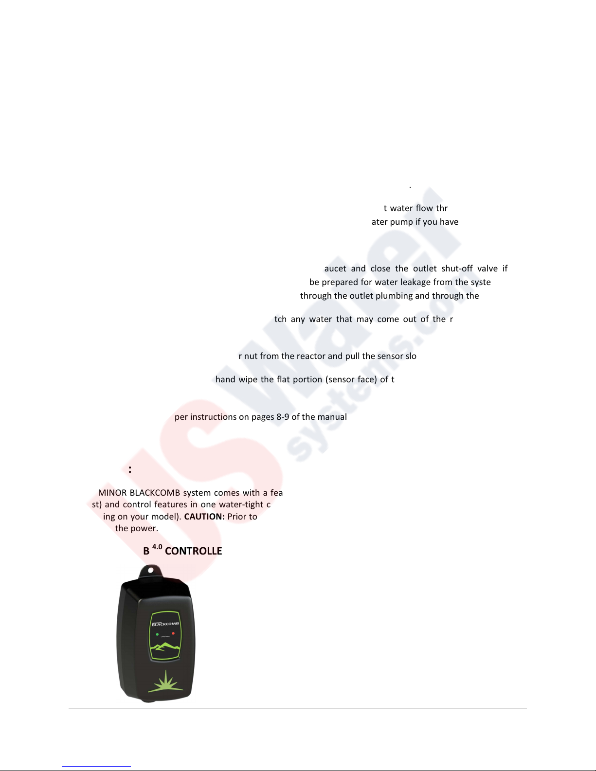
BLACKCOMB
4.0
CONTROLLER
This controller features a power factor corrected, constant current lamp
driver with a universal power input. Simplistic in operation, this system
features two LED’s that show lamp status. When the UV lamp is on, the
green LED will be illuminated. When the UV lamp is not on, the red LED
will be illuminated and an audible buzzer will be sounding. To remedy
this condition, the UV lamp must be replaced with a new UV lamp.
Please Note: While the red LED is illuminated and the buzzer is sounding
the water from the system should NOT be consumed. If any water does
pass through the system during this period, please follow the
12 | P a g e
Page 13
disinfection procedure as outlined in this manual before the water is
consumed. It should also be noted that even though this system has a
visual and audible warning built into the controller, the green LED does
not necessarily indicate that the water coming from this system is in fact
potable (safe to drink). This system does not measure the level of
disinfection; it simply measures the “on-off” status of the lamp. Please
have your water checked for microbiological contaminants on a regular
basis.
BLACKCOMB
5.0
& BLACKCOMB
6.0
CONTROLLER
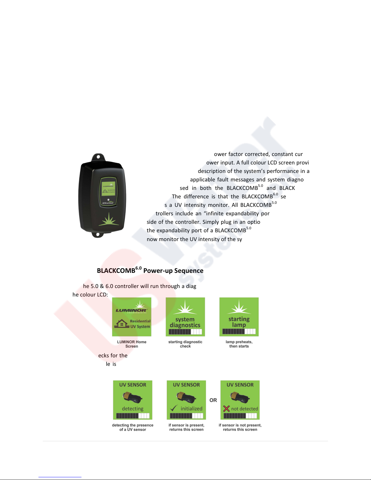
This controller features a power factor corrected, constant current lamp
driver with a universal power input. A full colour LCD screen provides the
user with a detailed description of the system’s performance in addition
to providing any applicable fault messages and system diagnostics. The
controllers used in both the BLACKCOMB
5.0
and BLACKCOMB
identical. The difference is that the BLACKCOMB
includes a UV intensity monitor. All BLACKCOMB
6.0
series of products
5.0
and BLACKCOMB
6.0
are
6.0
controllers include an “infinite expandability port” located on the right
side of the controller. Simply plug in an optional UV sensor module into
the expandability port of a BLACKCOMB
5.0
controller and the system will
now monitor the UV intensity of the system!
BLACKCOMB
5.0
& BLACKCOMB
Upon start up, the 5.0 & 6.0 controller will run through a diagnostic start-up and the sequence will be displayed as
follows on the colour LCD:
6.0
Power-up Sequence
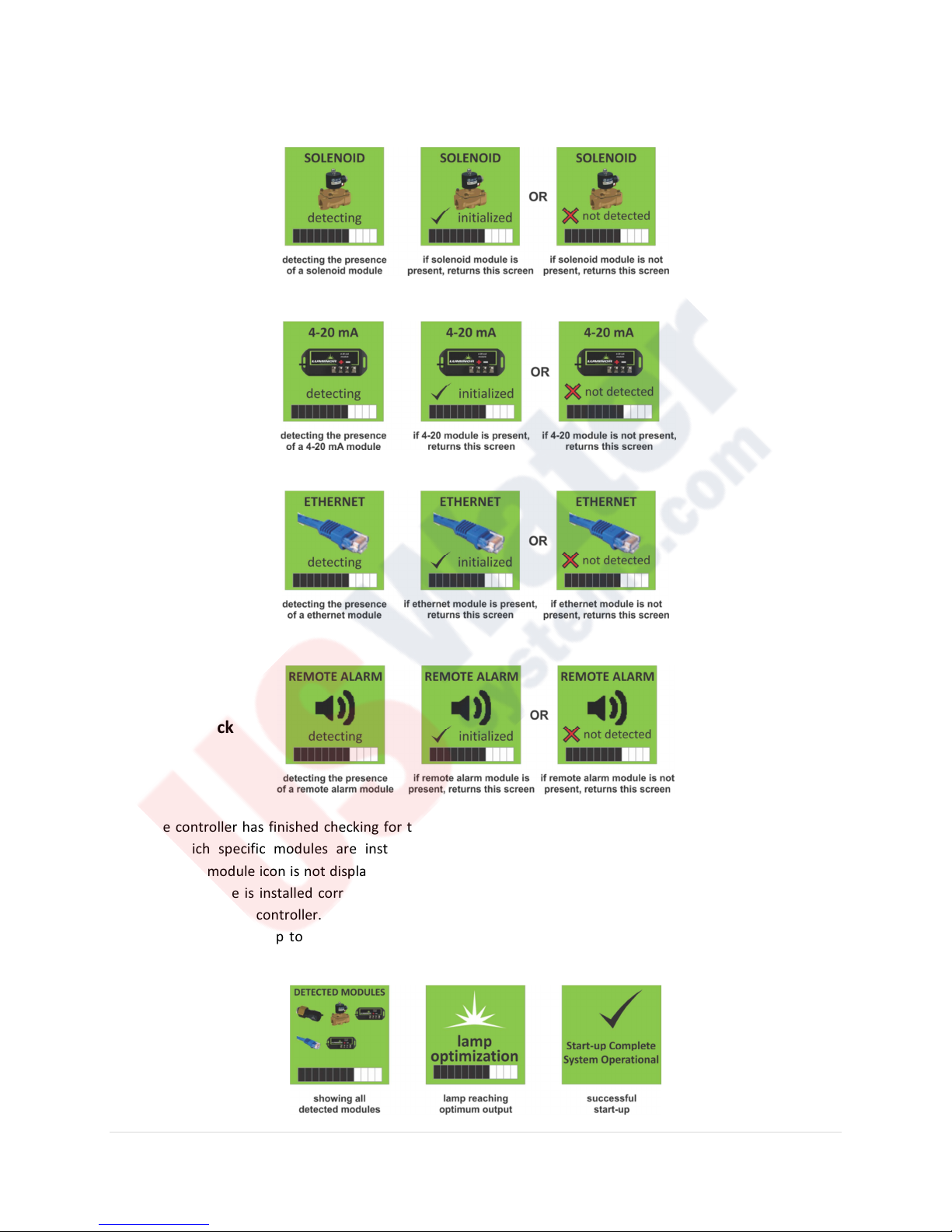
The controller next checks for the installation of any optional modules that may be installed on the system. It first
checks to see if a module is installed and then either initializes the module to function with the controller or
returns a “not detected” screen and moves on to the next module. The screens will appear as follows:
UV Sensor
Module Check
13 | P a g e
Page 14
Solenoid
Module Check
4-20 mA
Module Check
Ethernet
Module Check
Remote Alarm
Module Check
Once the controller has finished checking for the installation of all available modules a single screen is displayed
showing which specific modules are installed and activated on this particular system. Please Note: If the
corresponding module icon is not displayed on this screen, then that module is not installed on this system. If you
believe this module is installed correctly, recheck the applicable connections to ensure a solid connection point
and then restart the controller. The controller then continues to optimize the lamp efficiency by waiting 60
seconds to allow the lamp to reach its optimum output. Finally, a final “start-up complete” screen is displayed.
These screens will appear as follows:
14 | P a g e
Page 15
BLACKCOMB
button
button
5.0
Operational Screens
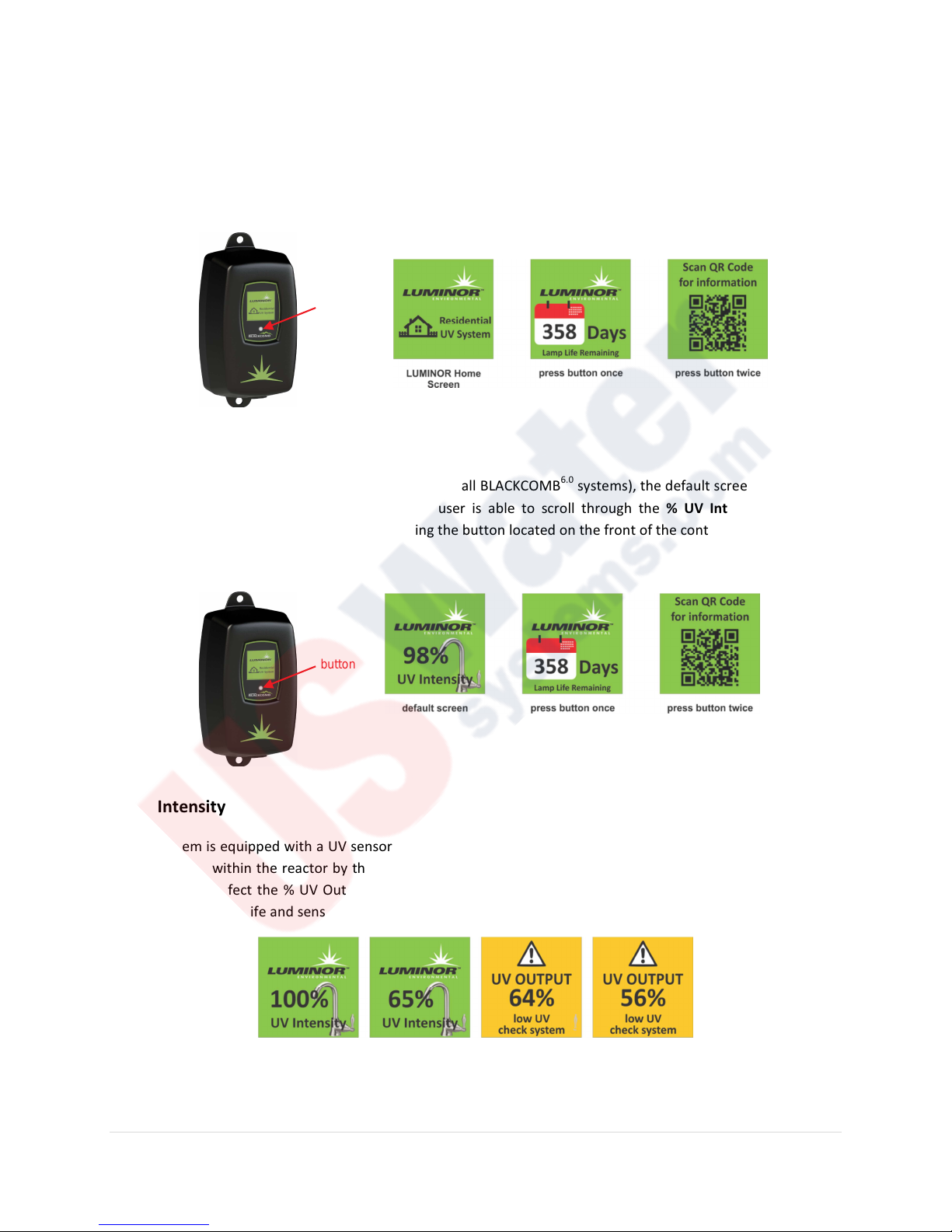
On BLACKCOMB
any point during operation the user is able to scroll through the LUMINOR Home Screen, Lamp life remaining and
QR Code/Contact Info screens by simply pressing the button located on the front of the controller.
5.0
systems (without the UV monitor), the default screen shows the LUMINOR Home Screen. At
BLACKCOMB
On systems that have the UV module installed (and on all BLACKCOMB
UV Intensity. At any point during operation the user is able to scroll through the % UV Intensity, Lamp life
remaining and QR Code screens by simply pressing the button located on the front of the controller.
6.0
Operational Screens
6.0
systems), the default screen shows the %
% UV Intensity
If your system is equipped with a UV sensor the % UV Output screens will indicate the level of UV intensity that is
being detected within the reactor by the sensor. This will always be visible on the Home Screen of the controller.
Things that can affect the % UV Output are poor water quality, scaling of the quartz sleeve and/or sensor, lamp
failure, expired lamp life and sensor failure. The following screens show the % UV Output dropping on a monitored
system.
Once the UV output drops below 56%, the numbers and warning sign switch to red and a 15 second intermittent
audible chirp is given off by the ballast. When the output drops below 51%, the display switches to a solid red and
15 | P a g e
Page 16
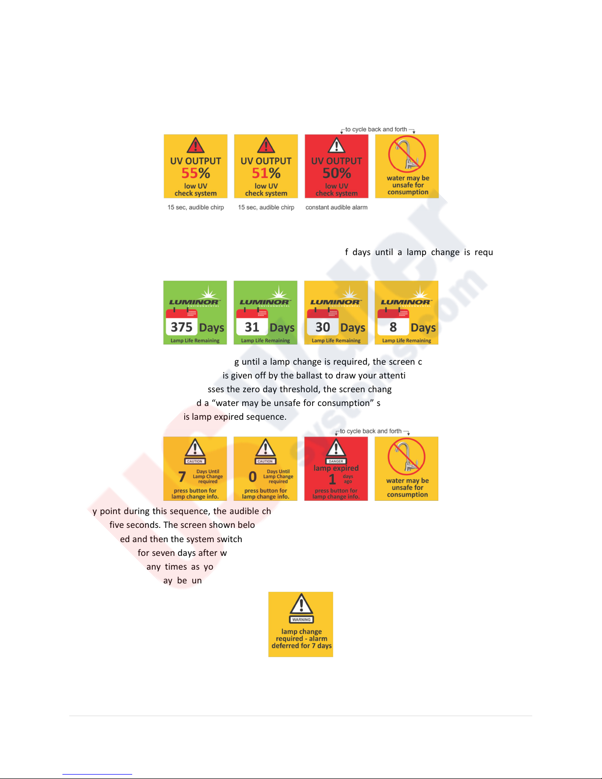
a constant audible signal is provided. The screens alternate between this solid red screen and another screen
indicating “water may be unsafe for consumption”. At this point, the controller also provides a signal to de-activate
the solenoid valve, shutting off the flow of water if a solenoid valve is installed on the system.
BLACKCOMB
The BLACKCOMB
operation is as follows:
5.0
& BLACKCOMB
5.0
& BLACKCOMB
6.0
Lamp Countdown Sequence
6.0
counts down the number of days until a lamp change is required. The
Once the lamp has seven days remaining until a lamp change is required, the screen changes to a yellow caution
screen. At this point, an audible chirp is given off by the ballast to draw your attention to the pending lamp change
condition. When the controller passes the zero day threshold, the screen changes to solid red and cycles between
a red “lamp expired” screen and a “water may be unsafe for consumption” screen. The same intermittent audible
chirp is heard throughout this lamp expired sequence.
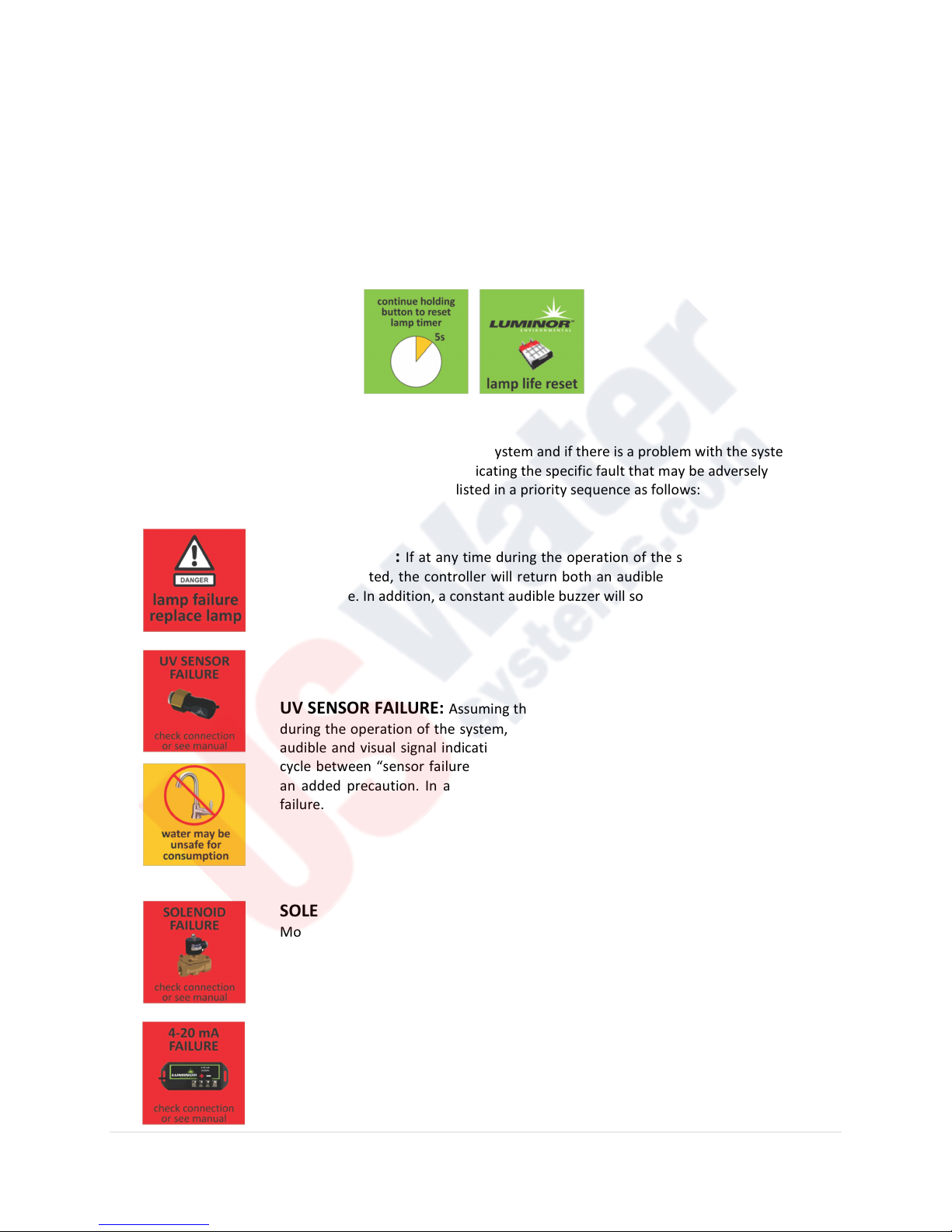
At any point during this sequence, the audible chirp can be deferred by holding the controller button down for a
period of five seconds. The screen shown below will appear for five seconds indicating that the audible defferal has
been activated and then the system switches back to the current lamp change or lamp expired screen. This audible
deferral will last for seven days after which then the alarm will sound once again. This audible deferral feature can
be activated as many times as you wish. PLEASE NOTE: During the condition of lamp expiration and audible
deferral, the water may be unsafe for consumption and should not be consumed without another form of
disinfection.
16 | P a g e
Page 17
BLACKCOMB
5.0
& BLACKCOMB
6.0
Lamp Countdown Reset Sequence
After changing the lamp on the BLACKCOMB
the system to begin its countdown function on the newly installed lamp. To perform this reset, you must firmly
depress the button on the front of the controller and then manually plug the power cord back into the wall outlet
initiating power to the unit. Keep holding down the button for five seconds until you hear an audible chirp
indicating the controller has reset the internal timer. Release the switch and the lamp countdown feature has now
been reset. The following two screens will be displayed during this process.
5.0
& BLACKCOMB
6.0
systems, the controller must be reset in order for
BLACKCOMB
The BLACKCOMB controller continuously monitors your UV system and if there is a problem with the system the
controller will provide both a visual and audible signal indicating the specific fault that may be adversely affecting
the operation of your system. The fault conditions are listed in a priority sequence as follows:
5.0
& BLACKCOMB
6.0
Failure Modes
LAMP FAILURE: If at any time during the operation of the system, the UV lamp fails
to be illuminated, the controller will return both an audible and visual signal indicating
lamp failure. In addition, a constant audible buzzer will sound during lamp failure.
UV SENSOR FAILURE:
during the operation of the system, a UV sensor fails, the controller will return both an
audible and visual signal indicating sensor failure. For sensor failure, the controller will
cycle between “sensor failure” and “water may be unsafe for consumption” screens as
an added precaution. In addition, a constant audible buzzer will sound during sensor
failure.
Assuming the system has a UV Sensor installed, if at any time
SOLENOID MODULE FAILURE: Assuming the system has an optional Solenoid
Module installed, if at any time during the operation of the system, a solenoid valve fails
to operate, the controller will return both an audible and visual signal indicating
solenoid failure. In addition, an intermittent (15 sec) audible buzzer will sound during
solenoid failure.
4-20 mA MODULE FAILURE: Assuming the system has an optional 4-20 mA
Module installed, if at any time during the operation of the system, a 4-20 mA module
fails, the controller will return both an audible and visual signal indicating a 4-20 mA
failure. In addition, an intermittent (15 sec) audible buzzer will sound during a 4-20 mA
failure.
17 | P a g e
Page 18
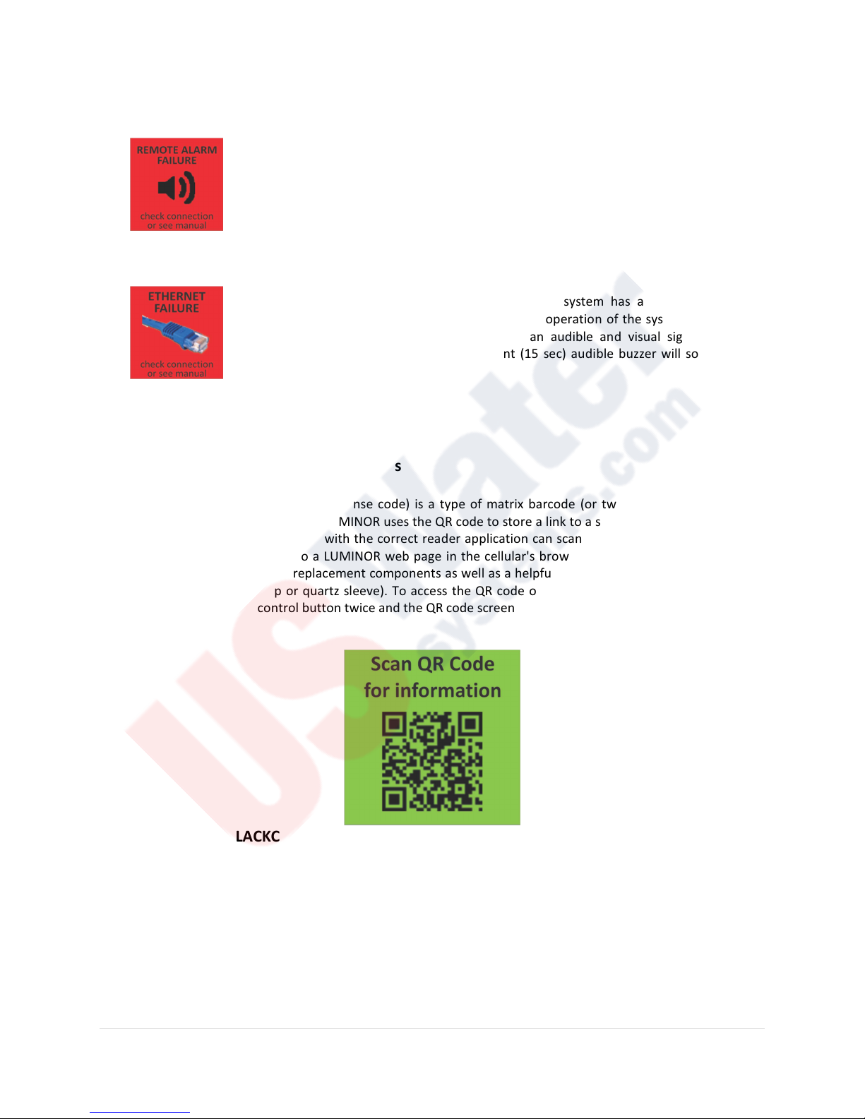
REMOTE ALARM MODULE FAILURE: Assuming the system has an optional
Remote Alarm Module installed, if at any time during the operation of the system, a
remote alarm module fails, the controller will return both an audible and visual signal
indicating remote alarm failure. In addition, an intermittent (15 sec) audible buzzer will
sound during remote alarm failure.
ETHERNET MODULE FAILURE: Assuming the system has an optional Ethernet
Alarm Module installed, if at any time during the operation of the system, an Ethernet
module fails, the controller will return both an audible and visual signal indicating
Ethernet failure. In addition, an intermittent (15 sec) audible buzzer will sound during
Ethernet failure.
BLACKCOMB
A QR code (abbreviated from Quick Response code) is a type of matrix barcode (or two-dimensional code) first
designed for the automotive industry. LUMINOR uses the QR code to store a link to a specific page on our website.
Users with a camera phone equipped with the correct reader application can scan the image of the QR code and
over a wireless network connect to a LUMINOR web page in the cellular's browser. LUMINOR’s QR webpage has
information on how to purchase replacement components as well as a helpful video directory on system servicing
(i.e. How to change a UV lamp or quartz sleeve). To access the QR code on the BLACKCOMB
controller simply press the control button twice and the QR code screen will appear as follows:
5.0
& BLACKCOMB
6.0
QR Codes
5.0
or BLACKCOMB
6.0
BLACKCOMB
5.0
& BLACKCOMB
As shown earlier in this manual, the BLACKCOMB
Expandability Port” (IEP) on the controller. It is through this port and via a custom communication protocol that
the UV sensor and all expanison modules are connected. Each module (including the sensor) comes with both a
male and female connection. To activate the device, you simply need to connect the first device (does not matter
which device it is) to the controller and all subsequent devices are then connected into the female end of the other
device. This “daisy chain” method allows for a truly modular approach and is extremely user friendly. An example
of this “daisy chain” is shown below.
6.0
Expansion Modules
5.0
and BLACKCOMB
6.0
controller incorporate an “Infinite
18 | P a g e
Page 19
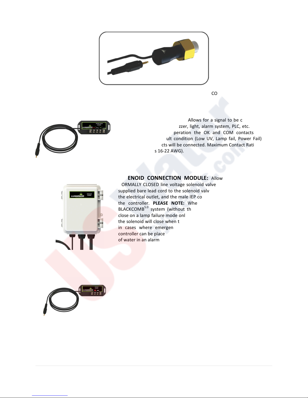
The following optional expansion modules are available for use on your BLACKCOMB
controllers. Contact your authorized distributor for purchasing information.
REMOTE ALARM MODULE: Allows for a signal to be connected to a
remote monitor such as a buzzer, light, alarm system, PLC, etc., via a pair
of contacts. In normal operation the OK and COM contacts will be
connected, and in a fault condition (Low UV, Lamp fail, Power Fail), the
Fault and COM contacts will be connected. Maximum Contact Rating is 1A120VAC/VDC (uses 16-22 AWG).
SOLENOID CONNECTION MODULE: Allows the integration of a
NORMALLY CLOSED line voltage solenoid valve. Simply affix the module's
supplied bare lead cord to the solenoid valve, connect the power cable to
the electrical outlet, and the male IEP connector to the female IEP port on
the controller. PLEASE NOTE: When this device is connected to a
BLACKCOMB
close on a lamp failure mode only. When used on a BLACKCOMB
the solenoid will close when the UV level drops below 50%. Also note that
in cases where emergency use of untreated water is required, the
controller can be placed into a manual override mode allowing for the flow
of water in an alarm condition.
5.0
system (without the UV module), then the solenoid will
4-20 mA MODULE: Allows for a 4-20mA signal transfer of the UV
output to a remote device such as a data logger or computer. Simply plug
the supplied cable into any female IEP connections. Two screw terminals
are supplied to connect the wire that leads to the receiving end of the
signal. As the distance required is unknown, no wire is supplied with this
system, however 16-22 AWG is required.
ETHERNET MODULE: Allows for all controller functions to be
connected to a computer via an Ethernet cable. This module is currently in
development and is not available at this point-in-time.
5.0
and BLACKCOMB
6.0
system,
6.0
19 | P a g e
Page 20
Warranty Registration
BLACKCOMB
4.0
It is imperative that you complete the warranty registration process. This not only registers your UV disinfection
system for the provided manufacturer’s warranty, but also allows the factory to provide you with any important
product updates or technical bulletins concerning your product. The registration process is a simple process and
can be done online at http://www.luminoruv.com/support_prodreg.php or by filling out the attached warranty
card. Please ensure that ALL information is filled in, including a valid e-mail address. PLEASE NOTE: This
information is for the sole purpose of technical support for your disinfection system and will not be used, or sold,
to any other organization for any other purpose. Please refer to LUMINOR’s Privacy Policy statement at
http://www.luminoruv.com/main_copyright.php for further information.
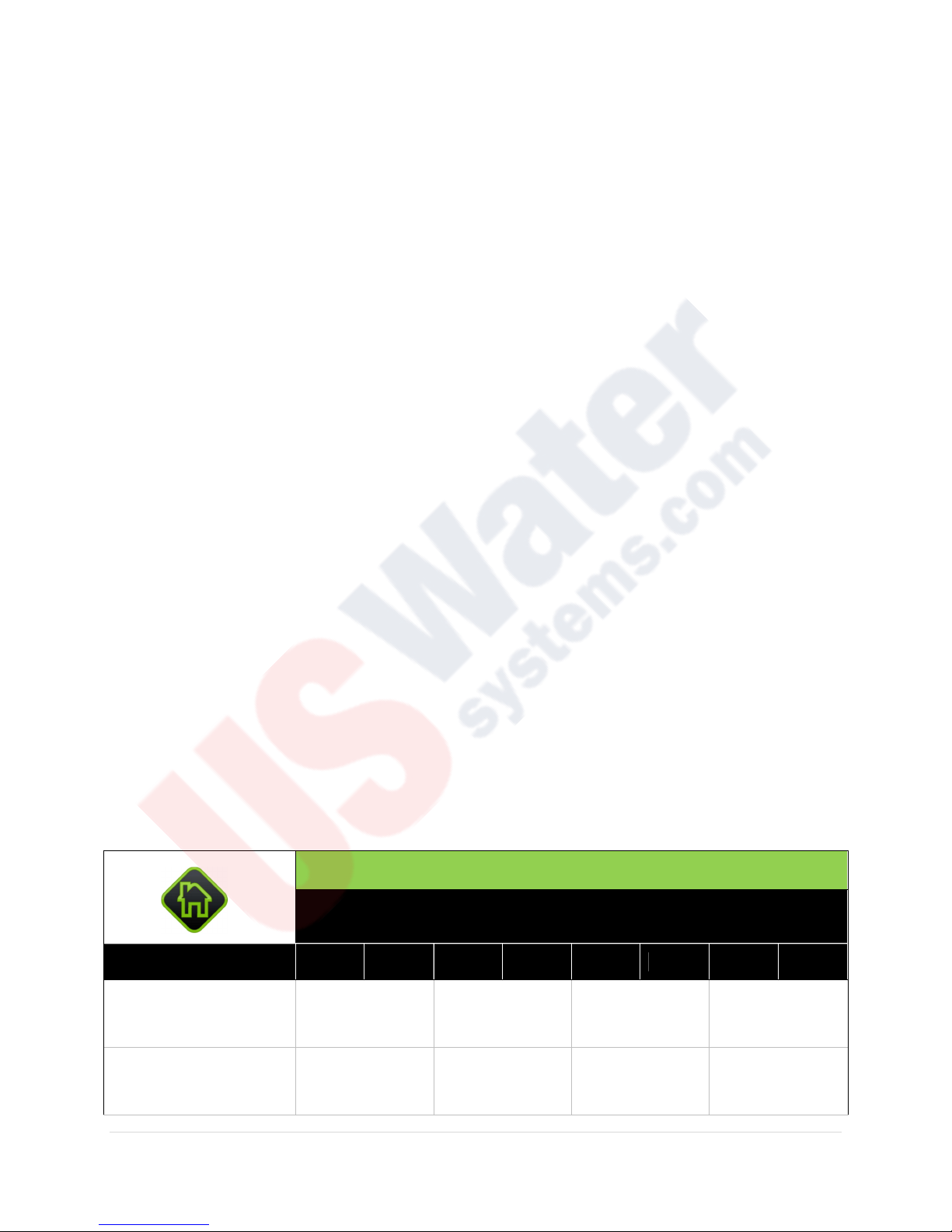
MODEL
Flow Rate (@ 16 mJ/cm2)
Flow Rate (@ 30 mJ/cm2)
LB4-031 LB4-032 LB4-061 LB4-062 LB4-101 LB4-102 LB4-201 LB4-202
LUMINOR EQUIPMENT SPECIFICATIONS
, Residential UV systems, modular non-
monitored
6.1 GPM 11.0 GPM 20 GPM 39.2 GPM
23 lpm 42 lpm 77 lpm 150 lpm
1.4 m3/hr. 2.5 m3/hr. 4.6 m3/hr. 8.9 m3/hr.
3.1 GPM 5.8 GPM 11 GPM 21 GPM
12 lpm 22 lpm 41 lpm 79 lpm
0.7 m3/hr. 1.3 m3/hr. 2.5 m3/hr. 3.6 m3/hr.
20 | P a g e
Page 21
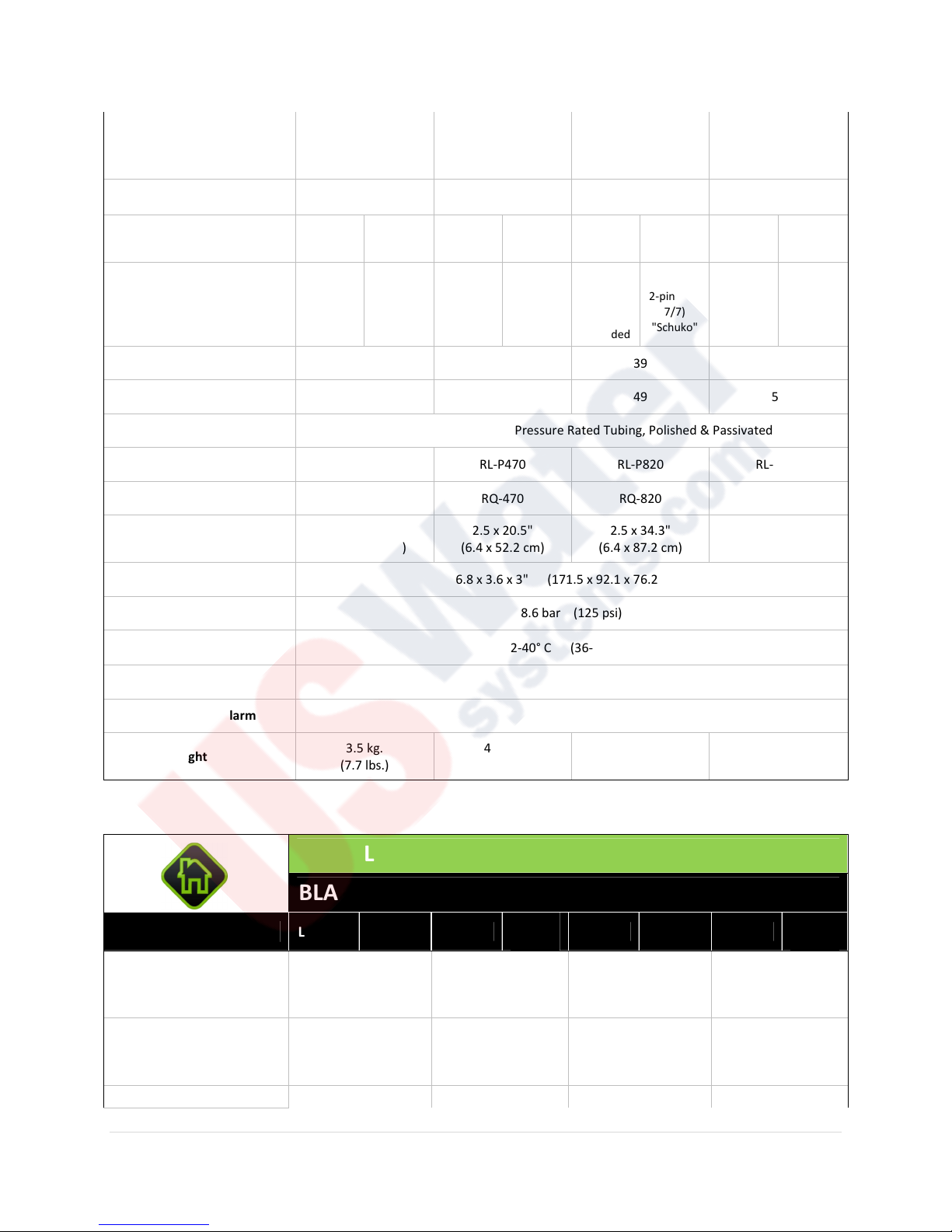
2.4 GPM 4.4 GPM 8.2 GPM 16 GPM
110V./
220V./
110V./
220V./
110V./
220V./
110V./
220V./
Flow Rate (@ 40 mJ/cm2)
Port Size ½" MNPT ¾" MNPT ¾" MNPT 1" MNPT
9.1 lpm 17 lpm 31 lpm 59 lpm
0.5 m3/hr. 1.0 m3/hr. 1.9 m3/hr. 3.6 m3/hr.
Electrical
Plug Type
Lamp Watts 15 22 39 42
Power (watts) 20 30 49 51
Chamber Material 304 Stainless Steel, A249 Pressure Rated Tubing, Polished & Passivated
Replacement Lamp RL-P290 RL-P470 RL-P820 RL-P850
Replacement Sleeve RQ-290 RQ-470 RQ-820 RQ-850
Reactor Dimensions
Controller Dimension 6.8 x 3.6 x 3" (171.5 x 92.1 x 76.2 mm)
Maximum Operating Pressure 8.6 bar (125 psi)
Operating Temperature
Range
Visual Lamp-Out Indicator Yes
50-60Hz.
American,
Nema
5/15, 3
prong
grounded
2.5 x 13.5"
(6.4 x 34.2 cm)
50-60Hz.
European,
2-pin (CEE
7/7)
"Schuko"
50-60Hz.
American,
Nema
5/15, 3
prong
grounded
2.5 x 20.5"
(6.4 x 52.2 cm)
50-60Hz.
European,
2-pin (CEE
7/7)
"Schuko"
2-40° C (36-104° F)
50-60Hz.
American,
Nema
5/15, 3
prong
grounded
2.5 x 34.3"
(6.4 x 87.2 cm)
50-60Hz.
European,
2-pin (CEE
7/7)
"Schuko"
50-60Hz.
American,
Nema
5/15, 3
prong
grounded
3.5 x 36.1"
(8.9 x 91.7 cm)
50-60Hz.
European,
2-pin (CEE
"Schuko"
7/7)
Audible Lamp-Out Alarm Yes
Shipping Weight
3.5 kg.
(7.7 lbs.)
4.0 kg.
(8.9 lbs.)
6.6 kg.
(14.6 lbs.)
7.3 kg.
(16.1 lbs.)
BLACKCOMB
MODEL
Flow Rate (@ 16 mJ/cm2)
Flow Rate (@ 30 mJ/cm2)
Flow Rate (@ 40 mJ/cm2) 2.4 GPM 4.4 GPM 8.2 GPM 16 GPM
LB5-031 LB5-032 LB5-061
LUMINOR EQUIPMENT SPECIFICATIONS
5.0
, Residential UV systems, modular non-monitored
LB5-
062
6.1 GPM 11.0 GPM 20 GPM 39.2 GPM
23 lpm 42 lpm 77 lpm 150 lpm
1.4 m3/hr. 2.5 m3/hr. 4.6 m3/hr. 8.9 m3/hr.
3.1 GPM 5.8 GPM 11 GPM 21 GPM
12 lpm 22 lpm 41 lpm 79 lpm
0.7 m3/hr. 1.3 m3/hr. 2.5 m3/hr. 3.6 m3/hr.
LB5-101 LB5-102 LB5-201
21 | P a g e
LB5-
202
Page 22
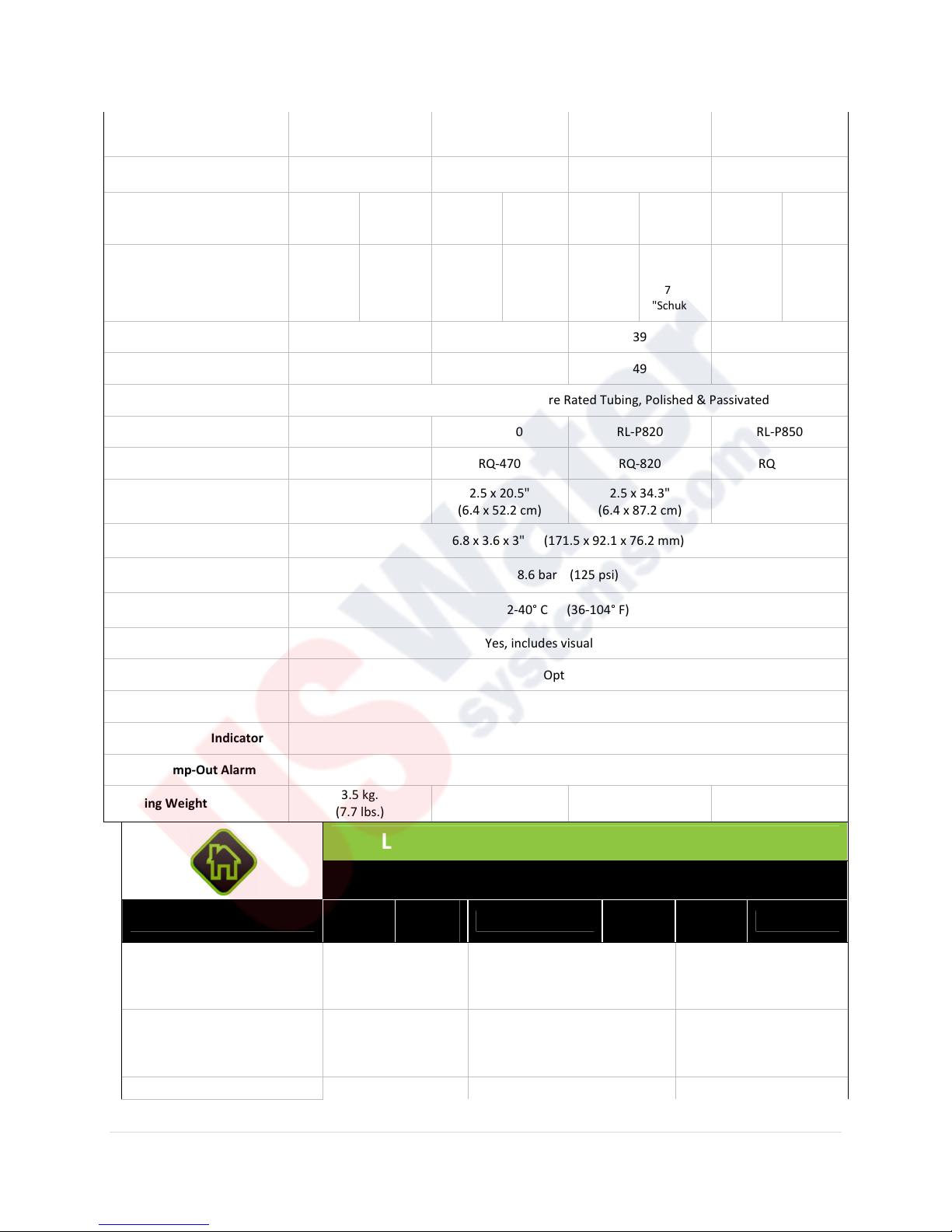
9.1 lpm 17 lpm 31 lpm 59 lpm
110V./
220V./
110V./
220V./
110V./
220V./
110V./
220V./
American,
American,
American,
American,
LB6
-
LB6
-
LB6
-
LB6
-
0.5 m3/hr. 1.0 m3/hr. 1.9 m3/hr. 3.6 m3/hr.
Port Size ½" MNPT ¾" MNPT ¾" MNPT 1" MNPT
Electrical
Plug Type
Lamp Watts 15 22 39 42
Power (watts) 20 30 49 51
Chamber Material 304 Stainless Steel, A249 Pressure Rated Tubing, Polished & Passivated
Replacement Lamp RL-P290 RL-P470 RL-P820 RL-P850
Replacement Sleeve RQ-290 RQ-470 RQ-820 RQ-850
Reactor Dimensions
Controller Dimension 6.8 x 3.6 x 3" (171.5 x 92.1 x 76.2 mm)
Maximum Operating
Pressure
Operating Temperature
Range
UV Monitor Port (upgrade) Yes, includes visual glow plug
50-60Hz.
Nema
5/15, 3
prong
grounded
2.5 x 13.5"
(6.4 x 34.2 cm)
50-60Hz.
European,
2-pin (CEE
7/7)
"Schuko"
50-60Hz.
Nema
5/15, 3
prong
grounded
2.5 x 20.5"
(6.4 x 52.2 cm)
50-
60Hz.
European
, 2-pin
(CEE 7/7)
"Schuko"
8.6 bar (125 psi)
2-40° C (36-104° F)
50-60Hz.
Nema
5/15, 3
prong
grounded
2.5 x 34.3"
(6.4 x 87.2 cm)
50-60Hz.
European,
2-pin (CEE
7/7)
"Schuko"
50-60Hz.
Nema
5/15, 3
prong
grounded
3.5 x 36.1"
(8.9 x 91.7 cm)
European
(CEE 7/7)
"Schuko"
50-
60Hz.
, 2-pin
Solenoid Output Optional
4-20 mA Output Optional
Visual Lamp-Out Indicator Yes
Audible Lamp-Out Alarm Yes
Shipping Weight
3.5 kg.
(7.7 lbs.)
4.0 kg.
(8.9 lbs.)
6.6 kg.
(14.6 lbs.)
LUMINOR EQUIPMENT SPECIFICATIONS
MODEL
Flow Rate (@ 16 mJ/cm2)
Flow Rate (@ 30 mJ/cm2)
Flow Rate (@ 40 mJ/cm2) 4.4 GPM 8.2 GPM 16 GPM
BLACKCOMB
061
11.0 GPM 20 GPM 39.2 GPM
2.5 m3/hr. 4.6 m3/hr. 8.9 m3/hr.
5.8 GPM 11 GPM 21 GPM
1.3 m3/hr. 2.5 m3/hr. 3.6 m3/hr.
062
42 lpm 77 lpm 150 lpm
22 lpm 41 lpm 79 lpm
6.0
, Residential UV systems, UV monitored
LB6-111
112
211
7.3 kg.
(16.1 lbs.)
LB6-212
22 | P a g e
Page 23
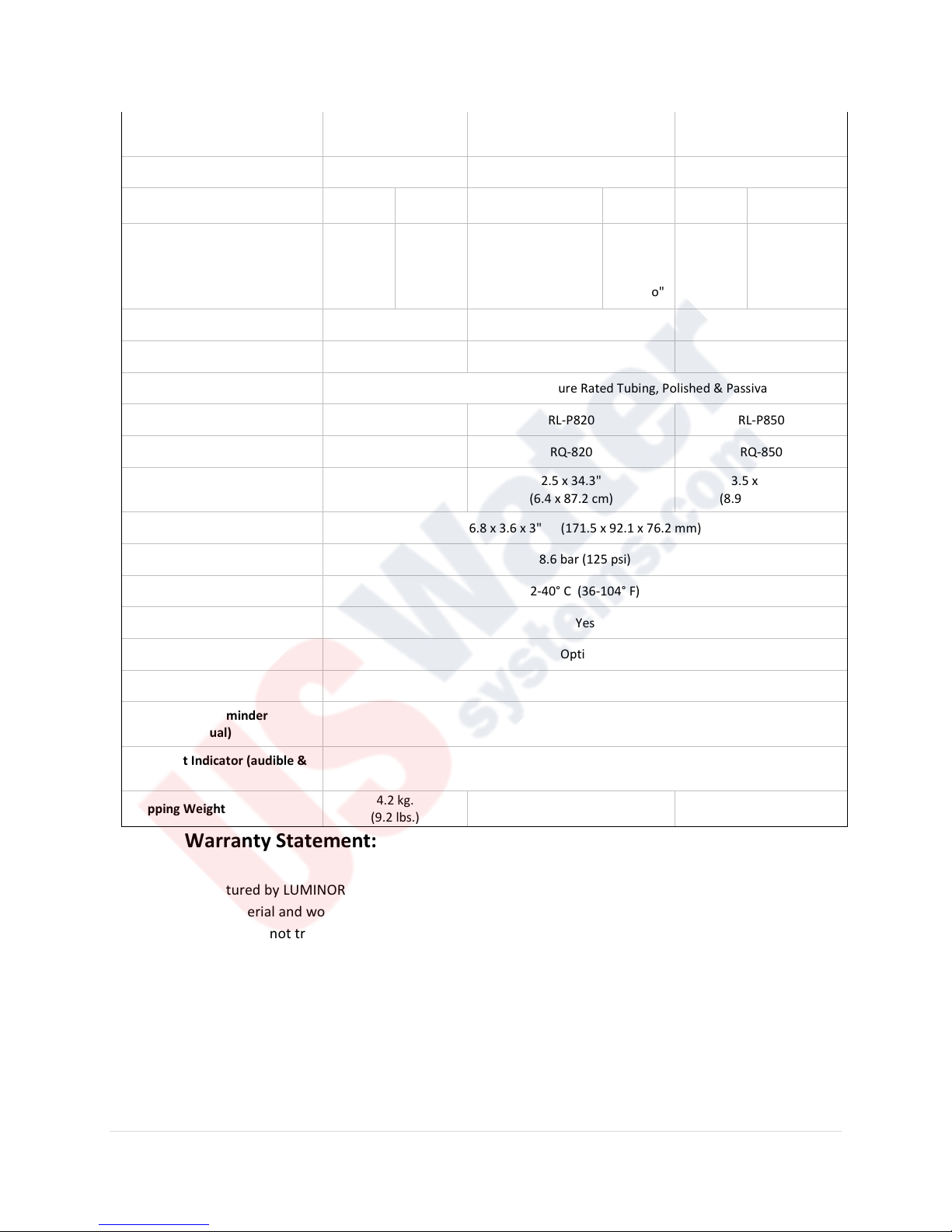
17 lpm 31 lpm 59 lpm
1.0 m3/hr. 1.9 m3/hr. 3.6 m3/hr.
Port Size ¾" MNPT ¾" MNPT 1" MNPT
Electrical
Plug Type
Lamp Watts 22 39 42
Power (watts) 30 49 51
Chamber Material 304 Stainless Steel, A249 Pressure Rated Tubing, Polished & Passivated
Replacement Lamp RL-P470 RL-P820 RL-P850
Replacement Sleeve RQ-470 RQ-820 RQ-850
110V./50
-60Hz.
American
, Nema
5/15, 3
prong
grounded
220V./50
-60Hz.
European
, 2-pin
(CEE 7/7)
"Schuko"
110V./50-60Hz.
American, Nema
5/15, 3 prong
grounded
220V./50
-60Hz.
European
, 2-pin
(CEE 7/7)
"Schuko"
110V./50
-60Hz.
American
, Nema
5/15, 3
prong
grounded
220V./50-
European, 2-
pin (CEE 7/7)
"Schuko"
60Hz.
Reactor Dimensions
Controller Dimensions 6.8 x 3.6 x 3" (171.5 x 92.1 x 76.2 mm)
Maximum Operating Pressure 8.6 bar (125 psi)
Operating Temperature Range 2-40° C (36-104° F)
UV Intensity Monitor Yes
Solenoid Output Optional
4-20 mA Output Optional
Lamp Change Reminder
(audible & visual)
Lamp-Out Indicator (audible &
visual)
Shipping Weight
2.5 x 20.5"
(6.4 x 52.2 cm)
4.2 kg.
(9.2 lbs.)
2.5 x 34.3"
(6.4 x 87.2 cm)
Yes
Yes
6.8 kg.
(15.0 lbs.)
3.5 x 36.1"
(8.9 x 91.7 cm)
7.5 kg.
(16.5 lbs.)
Limited Warranty Statement:
Products manufactured by LUMINOR Environmental Inc., (LUMINOR) are warranted to the original user only to be
free of defects in material and workmanship for a period as specified below. This warranty only applies to the
original purchaser and is not transferable.
UV SYSTEMS
Ten (10) year Limited Warranty on the stainless steel reactors, from the date of original purchase, or
installation (proper documentation required for verification).
ELECTRONICS
23 | P a g e
Page 24

Three (3) year Limited Warranty on the ballasts and controllers, from the date of original purchase, or
installation (proper documentation required for verification).
UV LAMPS, UV SENSORS & QUARTZ SLEEVES
One (1) year Limited Warranty on all LUMINOR ultraviolet lamps, UV sensors and quartz sleeves from
the date of original purchase, or installation (proper documentation required for verification).
LUMINOR warrants that it will repair, replace or refund, at LUMINOR’s sole option, any ultraviolet system or
component that is defective in materials or workmanship for the period as outlined above, subject to the
“Limitations of Warranty” as outlined below. LUMINOR's liability under this warranty shall be limited to repairing
or replacing at LUMINOR's option, without charge, F.O.B. LUMINOR’s factory or authorized service depot, any
product that LUMINOR manufactures. LUMINOR will not be liable for any costs of removal, installation,
transportation, or any other charges which may arise in connection with a warranty claim. Products which are sold
but not manufactured by LUMINOR are subject to the warranty provided by the manufacturer of said products and
not by LUMINOR’s warranty. LUMINOR will not be liable for damage or wear to products caused by abnormal
operating conditions, accident, abuse, misuse, unauthorized alteration or repair, or if the product was not installed
in accordance with LUMINOR’s printed installation and operating instructions.
LIMITATIONS OF WARRANTY
This warranty does not apply to any of the following:
• Water Quality Parameters lie outside of the following ranges
• Hardness > 120 mg/L (7 gpg)
• Iron > 0.3 mg/L (ppm)
• Manganese > 0.05 mg/L (ppm)
• Tannins > 0.1 mg/L (ppm)
• Turbidity > 1 NTU
• Transmittance (UVT) < 75%
• A product that has been incorrectly installed according to the technical installation manual.
• A product that has been modified in any manner, unless approved by the manufacturer.
• A product where the serial number has been altered defaced or removed.
• Damage caused by the use of parts that are not compatible, suitable and/or authorized by LUMINOR for
use with the product (e.g. non-original lamps or sleeves).
• Damage caused during shipment of the product.
• Water damage is found inside ballast housing or controllers.
• Product is installed outdoors in direct contact with the environment (rain).
• Product is installed in freezing temperatures.
• Product is used in conditions that exceed LUMINOR’s specifications.
TO GET WARRANTY SERVICE
To obtain service under this warranty, you must first contact LUMINOR Customer Service at 855-837-3801 (519837-3800 outside of the US or Canada) to obtain a Warranty Return Authorization. You will then need to return the
product through the LUMINOR Dealer or Distributor where the product was originally purchased, together with
24 | P a g e
Page 25

proof of purchase and installation date, failure date, and supporting installation data. Unless otherwise provided,
the Dealer or Distributor will contact LUMINOR for instructions on returning the product. Any defective product to
be returned to LUMINOR must be sent freight prepaid; documentation supporting the warranty claim and/or a
Return Material Authorization must be included if so instructed.
LUMINOR WILL NOT BE LIABLE FOR ANY INCIDENTAL OR CONSEQUENTIAL DAMAGES, LOSSES, OR EXPENSES
ARISING FROM INSTALLATION, USE, OR ANY OTHER CAUSES. THERE ARE NO EXPRESS OR IMPLIED WARRANTIES,
INCLUDING MERCHANTABILITY OR FITNESS FOR A PARTICULAR PURPOSE, WHICH EXTEND BEYOND THOSE
WARRANTIES DESCRIBED OR REFERRED TO ABOVE.
THIS LIMITED WARRANTY IS THE SOLE AND EXCLUSIVE WARRANTY MADE BY LUMINOR WITH RESPECT TO THE
PRODUCT, AND IS GIVEN IN LIEU OF ANY OTHER WARRANTY. TO THE EXTENT ALLOWED BY APPLICABLE LAW, ANY
AND ALL EXPRESS OR IMPLIED WARRANTIES NOT SET FORTH HEREIN ARE WAIVED AND DISCLAIMED, INCLUDING
ANY IMPLIED WARRANTY OF MERCHANTABILITY OR FITNESS FOR A PARTICULAR USE. LUMINOR LIABILITY UNDER
THIS LIMITED WARRANTY IS LIMITED SOLELY TO THOSE LIABILITIES SET FORTH ABOVE. IN THE EVENT THAT ANY
PROVISION OF THIS LIMITED WARRANTY SHOULD BE OR BECOME INVALID OR UNENFORCEABLE UNDER
APPLICABLE LAW, THE REMAINING TERMS AND CONDITIONS HEREOF SHALL REMAIN IN FULL FORCE AND EFFECT
AND SUCH INVALID OR UNENFORCEABLE PROVISION SHALL BE CONSTRUED IN SUCH A MANNER AS TO BE VALID
AND ENFORCEABLE.
25 | P a g e
Page 26
illuminating technologies for life
290 Southgate Drive, Unit 2
Guelph, Ontario, CANADA N1G 4P5
P: 519-837-3801
TF: 855-837-3801
F: 519-837-3808
info@luminoruv.com
www.luminoruv.com
26 | P a g e
 Loading...