

Page 1
NEXUS
NEXUS
WIRELESS ALERT
2a Bellevue Road, Friern Barnet, London N11 3ER
T. 020 8368 7887 F. 020 8368 3952
User Guide
www.luminite.co.uk
Designed and Manufactured in the UK
Page 2

Page 3

Table of Contents
1. Quick Start
2. Basic Description
3. Setup of Unit, Menu parameters
4. Installation on site: Site, Subnet, Unit
5. CALL Repeater
6. CALL Period
7. Master Unit
8. Serial Port
9. Indicator States
10. Operations (actions)
a) FIRE alert
b) STOP action
c) SILENT TEST ENABLE Action
d) SILENT TEST FIRE Action
e) SILENT TEST DISABLE Action
11. Battery State Reading
12. Maintenance
Page 4

1. Quick Start
1) Remove lid using a screwdriver. Please note the lid is tted with
push and quarter turn screws.
2) Taped inside the lid you will nd a black plastic key which is used
to re-set the call point along with the power jumper (JP2). You may
wish to nd a safe place to keep the re-set key.
3) Insert the batteries or if you are using your own batteries insert
these – please note that we recommend EVE ER34615 Lithium D
cells for maximum performance.
4) On the left hand side of the PCB board connect the JP2 jumper.
5) The LED screen will light up HI
6) Replace the lid – NEXUS is now ready to operate.
7) If you wish to test the system this is best done using the Master
unit with the external key. Press the black button on any call point.
The sounders and beacons within range will all start to operate
within seconds.
8) To cancel the test turn the external key on the Master to ON for
2 seconds. Sounders and beacons within range will stop in a few
seconds. If not, repeat this step.
9) To re-set the call point that was activated, insert the black plastic
re-set key into the bottom of the call point.
Page 5

10) Please note that resetting the call point does not reset the unit.
This must be done via the master external key.
11) If you wish to adjust the volume on the sounder, twist it off the
base-unit to access the switches underneath.
12) Follow the instructions on the base to change the sound level
and pattern if required.
Page 6

2. Basic description
The NEXUS Alert System consists of one or more battery powered
units all of which communicate to create a wireless network. The
maximum number of Units in a network (installed on one site) is 64.
NEXUS units complement wireless Genesis PIRs (both Genesis1
and Genesis2 types) and should not interfere or cause signicant
communication problems.
Master units are equipped with a re-set key and STOP button.
Other units are classed as Basic units and have only a FIRE button.
Basic Unit can be used for following actions:
- To activate FIRE Alert (when FIRE button broken & device is
in NORMAL OPERATION mode)
- To activate SILENT_TEST_FIRE (when FIRE button broken &
device is in SILENT_TEST mode)
- To deactivate SILENT_TEST_FIRE (when FIRE button xed &
device is in SILENT_TEST mode)
Master Unit has a FIRE button and a STOP button and can
be used for the same actions as Basic Units, plus the
following:
- To STOP ongoing FIRE Alert (stops Sounder and Lights of all
Units)
- To switch into SILENT TEST mode or back to NORMAL
OPERATION mode
Page 7

Master Unit has a FIRE button and a STOP button and can be used
for the same actions as Basic Units, plus the following:
- To STOP ongoing FIRE Alert (stops Sounder and Lights of all
Units)
- To switch into SILENT TEST mode or back to NORMAL
OPERATION mode
Master Unit(s) should be installed in a room that is not accessible
to the public, only to person(s) authorised to carry out NEXUS Alert
System maintenance/service.
Operations made by Master Units can also be made by the Genesis
IP Masthead if such a feature is supported. The IP Masthead via
TCP Client can enter commands that will control these operations
(or NEXUS/NVR can do the same automatically).
Possible congurations of the NEXUS System are:
- One or more Basic Units + One or more Master Units
- One or more Basic Units + One or more Master Units + IP
Masthead
- One or more Basic Units + IP Masthead, (no Master Unit) –
not recommended
Recommended is to have at least 1 Master Unit on site, even if IPMasthead with AlarmSystem/NVR have control over the Fire Alert
System. The Master Unit can serve as a “rst aid”,
i.e. to STOP Fire Alert if automatic control fails.
Page 8

3. Setup of Unit, Menu Parameters
Both Basic and Master Units contain the same hardware.
On the bottom left corner of the PCB is [88] display with 4 buttons
underneath. (The button “X” next to the display is currently not
used).
Buttons and display provide user interface to the conguration of
the parameters. The buttons are:
(Select) II> ^ (Up)
(Memory) M v (Down)
How to use it:
If the display is completely off (no segment lights), then the device
is working normally.
In order to access the Setup Menu, press Select button and hold it
down until display wakes up (anything displayed). Now press the
Select button repeatedly to scroll between available Parameter
names.
When you stop touching the Select button, after a few seconds it
will flash the current value of the selected Parameter. Use buttons
Up/Down to edit the value.
Tip: hold Up or Down pressed, it counts automatically.
After setting the Parameter to the desired value (or leaving it
without change) continue with the Select button. Scroll to the next
Parameter name you need to edit, set it; repeat until all Parameters
have desired values.
Page 9
In order to “Apply” all changes (at once) and store the new Setup
values to EEPROM, press Memory button and hold it down, until
displaying of “bottom segments” changes to “upper segments”.
This takes about 5 seconds. Then release the Memory button and
the Parameters are saved. The device will reset itself and re-start
with updated parameters loaded from EEPROM. (Shows “HI” on
display shortly after Reset).
If the Memory button is pressed and released before the “upper
segments” are displayed, then the device makes “Cancel” operation,
ignores the Parameter changes and will self-Reset and restart with
the old parameters. No changes will be saved.
Tip: if you need to RESET the Unit, just hold Memory or any of the
4 buttons until Display wakes up, then press the Memory button
repeatedly to “Cancel” the operation.
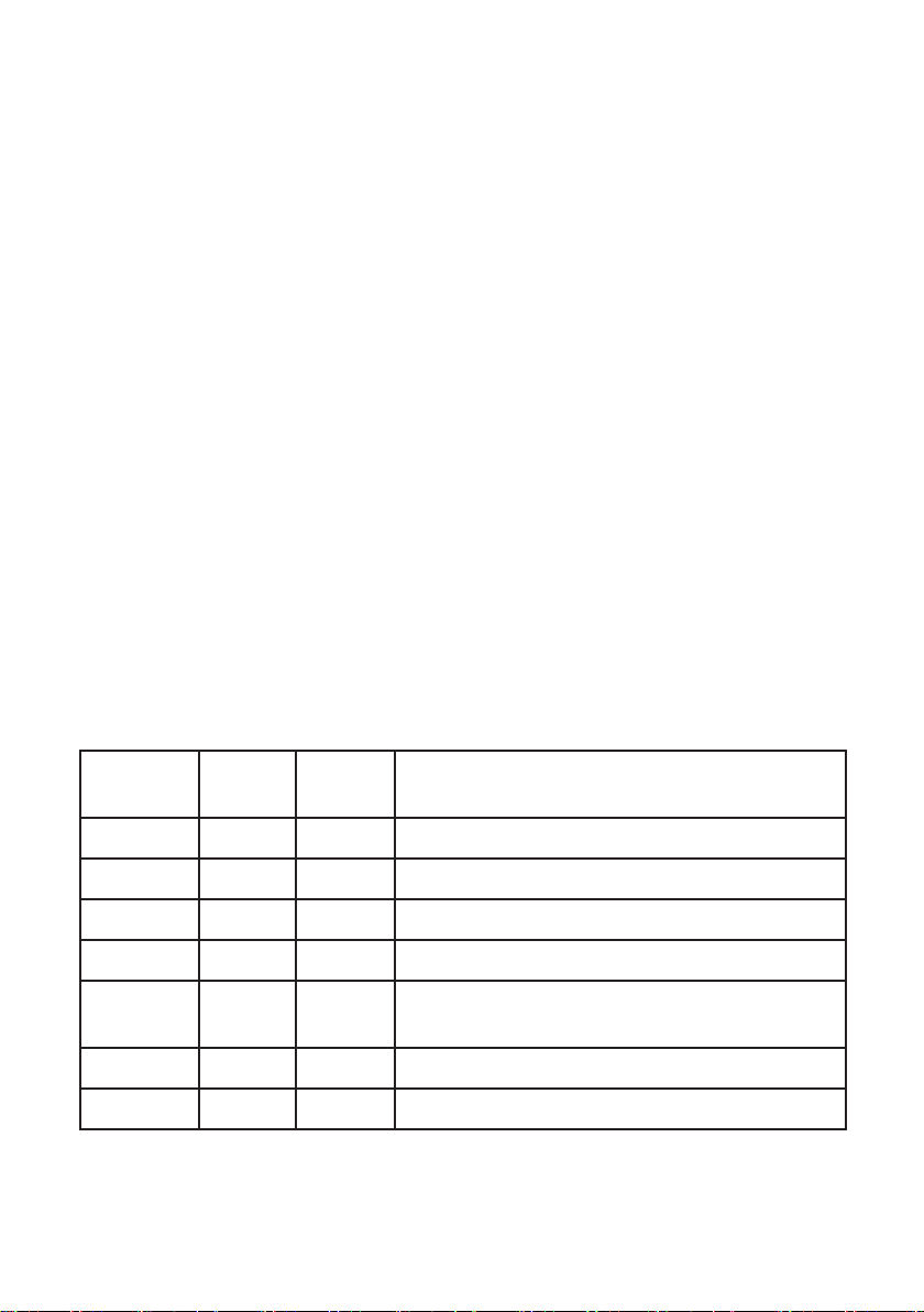
Parameters available:
Name
displayed
SI 1..32 1 Site
SU 1..8 1 Subnet
Un 1..64 1 Unit
Cr 0/1 1 CALL Repeater, 1=Enabled / 0=Disabled
CP 3..99 30 CALL Period, values 3..50 are [minutes],
MU 0/1 0 Master Unit, 1=Enabled / 0=Disabled
SP 0/1 1 Serial Port, 1=Enabled / 0=Disabled
Range Default
Value
Meaning
values N=51..99: time = 50+(N-50)*5 minutes
Page 10

4. Installation on site: Site, Subnet, Unit
If an IP Masthead is being used then read its SITE and SUBNET
settings. These can be set via DIP switches on the PCB board or
via command, values are visible on begin of initial text printed on
(power-up) Reset.
The same Site & Subnet numbers must then be congured on all
NEXUS Units.
All Basic Units and Master Units must have individual Unit numbers
and the same Site & Subnet.
If the NEXUS System is being used without an IP Masthead, then
choose any Site & Subnet.
Each of the NEXUS Units must have a unique Unit number which
cannot be repeated. Numbers can be the same as those used
for PIRs (if operating these with the same IP Masthead). Sharing
the same Unit number between NEXUS Units and Genesis PIRs
causes no conflict.
Please do not t NEXUS units directly to a metal wall as this
interferes with the signal. If you cannot avoid this, we recommend
spacing the unit away from the metal wall with a 5cm wooden
baton.
Page 11

5. CALL Repeater
Each unit regularly transmits CALL messages. These messages
serve as a “heartbeat”, carrying information about the battery status
and enabling the Masthead to track the Unit and check it alive and
working.
If all NEXUS Units are in RF transmission/reception range of the IP
Masthead, then there is no need to use Repeaters and all Units can
have SET CALL REPEATER Disabled.
Some sites, such as those with thick walls or walls combining
metal and concrete can prove problematic for transmission and
in these circumstances a Repeater may have to be used. In these
cases the Unit must have the “CALL REPEATER ENABLED and this
will support the propagation of CALL messages.
It is not recommended to have all Units in CALL REPEATER
ENABLED mode as such units make more retransmissions. Only
use this mode when repeaters are used – this will also save on
battery power.
Page 12

6. CALL Period
CALL Period is the nominal period of regular CALL transmission.
The real periods are random, around +/-6% to the nominal value (to
prevent collisions).
The call periods can be set from 3 minutes up to 295 minutes (4.9
hours)
Parameter Value Time
3..50 3..50 minutes
51 55 minutes
52 60 minutes
... ... time = 50+(N-50)*5 minutes
99 295 minutes; time = 50+(99-50)*5 = 295 minutes
Under normal circumstances the Parameter Value will be the same
on all the NEXUS Units, but each can be set with different values if
required.
Please note that the smaller the value, the shorter the battery life,
however shorter values also mean a faster refresh indicating the
health of the unit to the Masthead.
Page 13

7. Master Unit
This parameter is currently not used. Reserved for future versions
of rmware.
8. Serial Port
It is recommended that you keep Serial Port Enabled. If no RS232
cable is connected to dedicated pins of CON4, then RS232_circuit is
automatically switched to power-down mode, so it takes no additional current.
9. Indicator states
The LED inside the NEXUS FIRE button serves as indicator.
Some NEXUS Alert System actions/operations may take about a
minute, and during certain states user must wait until unit is ready
for another operation.
For example, when user presses the FIRE button, the NEXUS
unit starts immediately (Sounder & Light ON) and also starts RF
transmission with many repetitions to guarantee it will propagate to
all other units.
During this long RF transmission series the indicator is permanently
ON (for about 1 minute), which means the function is Busy and
should not be interrupted.
Page 14

Master Units are equipped with three types of transmission:
STOP (to stop all Units’ sounders and lights), SILENT TEST
ENABLE and SILENT TEST DISABLE.
These transmissions also need to propagate to all other units and
take about 1 minute, which is indicated as Busy.
Possible indicator states are:
a) permanently ON (about 1 minute) means Busy making a
long transmission series
b) toggling ON/OFF with period 1s …………. “Silent Test
Enabled” // ready for Silent Test
c) toggling ON/OFF with period 200ms ….. “FIRE button left
activated” // don’t forget to x it !
d) permanently_OFF …………………………………..“Ready” for FIRE
activation, normal state, taking low current
e) mostly OFF, 200ms flash every 3s …………. like d), but also
indicating “Battery Low”
f) permanently_OFF but appears several seconds ON ……
means “Short Activity”, probably making CALL or CALL-
retransmission
Page 15

10. Operations (actions)
a) NEXUS FIRE Alert
Normally, the NEXUS Fire Alert Unit should be indicating “Ready”
state.
If indicating “Battery Low” then replacement of batteries is
required. Use 2 x Lithium battery type EVE ER34615 (D-cell, 3.6V,
19Ah). Before removing the batteries from the device, unplug
jumper JP2. After insertion of the two cells plug the jumper back to
switch On. “HI” appears on the LED display for 1second.
Please note that when unit is in “Ready” or “Battery Low” mode the
average power consumption is below 500uA.
FIRE button (glass switch) is in Idle position, ready for Fire Alert.
Note: FIRE button must be at least 10s in Idle position before it is
ready for Fire Alert. Don’t forget to wait a bit after switching the unit
On via jumper JP2.
In the case of FIRE situation, the FIRE button can be pressed (glass
broken).
Once activated, the beacon containing sounder and strobe
starts a 6 second long initial RF transmission as well as a series
of other transmissions, total time of transmissions is about 1
minute. During this time a “Busy” state is indicated (indicator LED
permanently ON).
Page 16

Each unit that receives the FIRE Alert message activates it’s
own beacon and makes it’s own transmission as above. This
mechanism enables propagation to all NEXUS Units installed on
site, as long as they have the same Site and Subnet settings.
The speed of NEXUS Alert propagation depends on many factors,
particularly the maximum distance between units. If the distance
is more than the RF link range, then one or more units must serve
as Repeaters and each re-transmission increases the propagation
delay.
If all mutual distances between all units are lower than the RF link
range, then reactions should be very quick and all units could be
activated within a few seconds (by the initial 6s long transmission).
The FIRE Alert action ends about 1 minute after activation of
Source Unit.
The indicator on all units indicates “Busy” until the STOP button on
the Master unit has been activated.
An exclusion is only the Source Unit, whose indicator changes, it
shows “FIRE button left activated”; remains indicating this state
until FIRE button reverted to Idle position.
Note: If the FIRE button is activated on one unit (i.e. Source Unit) it
can be reverted back to Idle state immediately. In this scenario the
sounder will stop after 10 seconds, this being the minimum activity
length. The strobe would remain ON. This should only enable to
recognize the Source Unit has the FIRE button xed. But still, all
other units have both Sounder & Light activated.
The only way to stop everything is to make STOP Action.
Page 17

b) Stop Action
When one or more units have activated their sounders and strobe it
is possible to stop them all via STOP Action. Press the STOP button
on any Master Unit, hold it down for about 4 seconds (must be
between 2 and 10 seconds) and then release the button. You do not
have to wait for all NEXUS units to be activated before performing
this action.
The display will change to “Busy” (immediately when the STOP
button is released) and the unit will start it’s 6 second long initial
RF transmission plus a series of other transmissions, total time of
transmissions is about 1 minute. During this time a “Busy” mode is
indicated (indicator LED permanently ON).
It is similar process like FIRE Alert, but now a STOP message is
being propagated; as it is a newer message, it has priority over FIRE
Alert messages (if not nished yet). So, propagation of FIRE Alert
messages is stopped and replaced with STOP messages.
Each NEXUS unit receiving the STOP message deactivates it’s
Beacon (both sounder and strobe) and launches a series of
re-transmissions for the rest of the 1 minute period. This
mechanism enables propagation to all NEXUS Units installed on
site (only those with the same Site and Subnet settings).
The STOP action ends about 1 minute after releasing the STOP
button on the Master Unit. Indicators on all units should change
within one second - “Busy” mode will change to “Ready” (indicator
permanently OFF).
Page 18

Note: If the FIRE button on the Source Unit is still activated (not
reverted back yet) then this unit’s indicator shows “FIRE button left
activated”; remains indicating this state until FIRE button reverted
to Idle position.
Person authorized for Fire Alert System maintenance should check
that all units indicate “Ready” state (indicator permanently OFF).
Then only the system is ready for next FIRE Alert.
Troubleshooting:
In some cases the STOP message may not be delivered to all units
and some (one or more units) remain with beacons activated. In
this situation wait until the Master Unit (used) indicates “Ready”
state (i.e. previous 1 minute transmission series has nished) and
repeat the STOP Action activation (hold STOP for 4 seconds and
release). A new STOP transmission series will start.
It is possible, that STOP Action will have to be repeated up to 3
times.
If the STOP Action has still failed after three attempts then follow
these steps:
- wait at least 6 minutes, then repeat the STOP Action again.
Page 19

c) SILENT TEST ENABLE Action
This can only be carried out if all units indicate “Ready” mode.
Press the STOP button on any Master Unit, and hold it down until
the indicator goes ON (changes to “Busy” mode – takes about 10
seconds) then release the button.
Indicator shows “Busy” mode and the unit starts a 6 second long
initial RF transmission and series of other transmissions - the total
time of transmissions is about 1 minute; during this 1 minute a
“Busy” state is indicated (indicator LED permanently ON).
Each unit that receives the SILENT TEST ENABLE message
changes the indicated state from “Ready” (permanently OFF) to
“Busy” (permanently ON) and launches a series of re-transmissions
(for the rest of the 1 minute period). This mechanism enables
propagation to all NEXUS Units installed on site (that have the same
Site and Subnet settings).
This action lasts about 1 minute from the STOP button being
pressed. Indicators on all units should change at the same moment
(within one second). “Busy” mode changes to “Silent Test
Enabled” (toggling ON/OFF with 1 second period).
All units that received SILENT TEST ENABLE message (including
the Master Unit which initiated it) are now ready for SILENT TEST.
Page 20

d) SILENT TEST FIRE Action
This can only be carried out on units that indicate “Silent Test
Enabled” mode (toggling ON/OFF with 1 second period).
If a FIRE button is pressed (activated) on a unit that indicates a
“Ready” state, then it launches normal FIRE Alert that activates also
all Sounders !
Press the FIRE button on one unit (selected for testing).
Indicator shows “Busy” mode and the unit starts 6 seconds long
initial RF transmission plus series of other transmissions, total time
of transmissions is about 1 minute. During this time a “Busy” mode
is indicated (indicator LED permanently ON).
As this unit indicated “Silent Test Enabled” instead of normal
“Ready” state, it starts a transmission of SILENT TEST FIRE
message instead of normal FIRE Alert message.
Only units that have been switched to “Silent Test Enabled” mode
will react to this action.
Each unit that receives the SILENT TEST FIRE message switches
strobe light ON (sounder remains OFF) and launches a series
of retransmissions (for the rest of the 1 minute period). This
mechanism enables propagation to all Fire Units installed on site
(that have the same Site and Subnet settings).
Page 21

After the 1 minute long indication of “Busy” mode (permanently ON,
during transmission series) the unit reverts to the original indication
of “Silent Test Enabled” (toggling ON/OFF with 1 second period).
If the Source Unit (unit whose FIRE button was activated) has the
FIRE button still in active position, then this unit’s indicator shows
“FIRE button left activated” and continues to show this mode until
the FIRE button is reverted to the Idle position.
Reverting the FIRE button back to the Idle position launches a new
transmission now, it is SILENT TEST DONE mode that takes 1
minute and all units will switch Light OFF.
When all units have Light OFF, the system is now ready for testing
of another unit.
If necessary, repeat this action with all units. This will verify that all
FIRE buttons are operating correctly and that transmission range is
correct and reaching all units (and Masthead if used).
Page 22

e) SILENT TEST DISABLE Action
Any Master Unit that currently indicates “Silent Test Enabled” state
(toggling ON/OFF with 1 second period) can be used to Disable this
function.
Press the STOP button on any Master Unit and hold it down until
the indicator goes ON (changes to “Busy” mode - should take about
10 seconds), then release the button.
Indicator shows “Busy” mode and the unit starts about 6 second
long initial RF transmission plus series of other transmissions, total
time of transmissions is about 1 minute. During this time a “Busy”
mode is indicated (indicator LED permanently ON.
Each unit receiving the SILENT TEST DISABLE message changes
the indicated mode from “Silent Test Enabled” (toggling ON/OFF
with 1 second period) to “Busy” (permanently ON) and launches a
series of re-transmissions (for the rest of the 1 minute period). This
mechanism enables propagation to all NEXUS Units installed on
site (that have the same Site and Subnet settings).
This action ends about 1 minute after launching it via the STOP
button on the Master Unit. Indicators on all units should change
at the same time (within a second). None will indicate a “Busy”
modes but will change to “Ready” (permanently OFF).
All units that received SILENT TEST DISABLE message (including
the Master Unit which initiated it) are now ready for normal
operation.
Page 23

11. Battery state reading
This function is only available if you are using the IP Masthead.
In order to update information about the battery voltage it is
necessary to make operation SILENT TEST ENABLE via any
Master Unit and then make SILENT TEST FIRE.
All units that receive this command and switch Light ON (with
Sounder OFF) will make a battery voltage reading during the rst
7 seconds of this Light flashing. The current pattern of the Strobe
Light is known and microcontroller is able to measure and analyze
Battery state during operation of Strobe Light used as a load. If
measurement is completed successfully, then “last known” Battery
Voltage is registered and this value expressed in [%] is carried in
CALL messages (so IP-Masthead users can read it).
As a 100% is taken voltage 7.2V (== 2 x 3.6V Lithium Batteries in
serial).
Voltage is also compared with threshold, if lower than 70% (i.e.
5.04V) then “Battery Low” indication overrides “Busy” indication.
This will last until next SILENT TEST FIRE is launched.
Page 24

12. Maintenance
Person(s) authorised for NEXUS Alert System maintenance/service
should make note of the following:
• Check battery status of all units once a month.
• At least once a month check that all units are in RF link
range from the Master Unit. Carry out the SILENT TEST
ENABLE action and check all units are indicating “Silent
Test Enabled” state (toggling ON/OFF with 1 second period.
Then make a STOP Action and check all units are indicating
“Ready” state (permanently OFF).
• Once a week check that all units are indicating “Ready” state
(permanently OFF)
• If a new Unit or more Units are installed or changed position,
then carry out complete testing; see chapter 10 / SILENT
TEST ENABLE + SILENT TEST FIRE + SILENT TEST DONE
+ SILENT TEST DISABLE;
Page 25

 Loading...