

Page 1
Level - Installation Instructions
Please read all instructions prior to installation and keep for future reference!
1. Product to be installed by a qualied electrician.
2. Prior to installation ensure power is off at fuse box to prevent electrical shock.
3. All 120VAC wires must be present in junction box.
4. More than one person is recommended for this installation.
1
fixture
wall
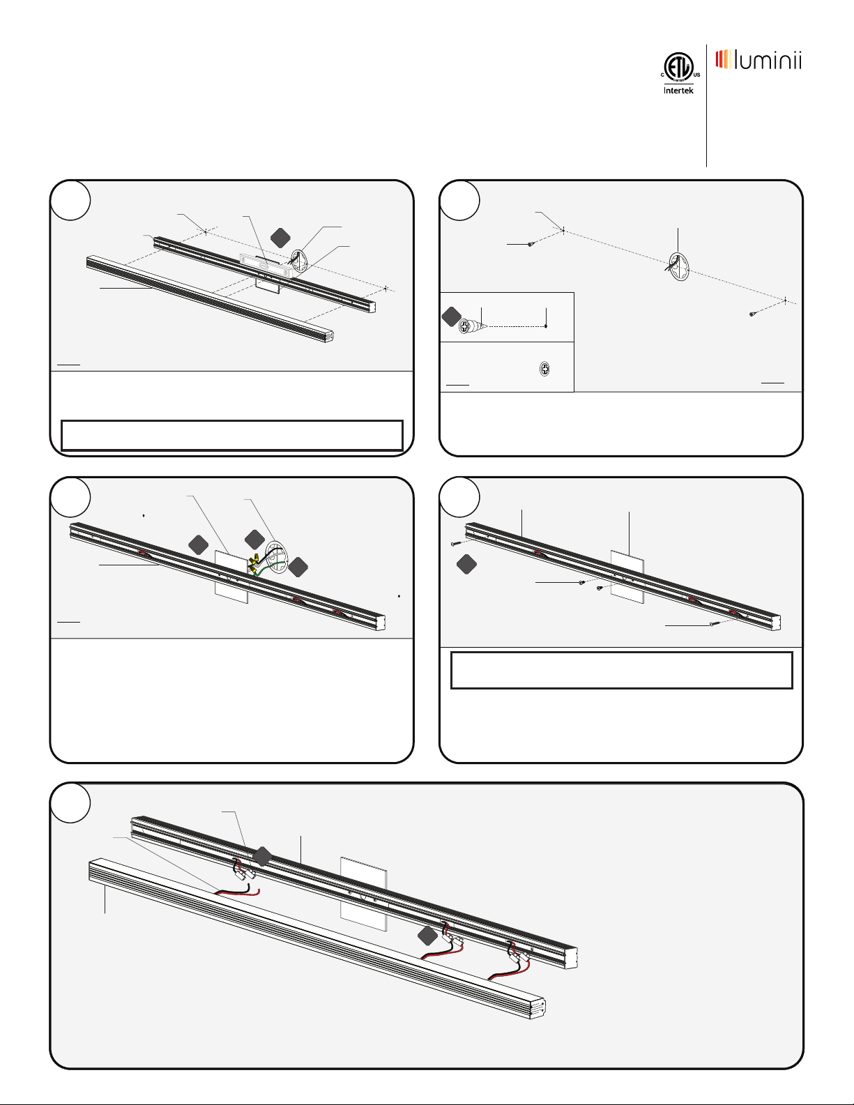
1.1 Lay the fixture next to the wall. Use a level to align & center the
fixture to the junction box. Make any necessary markings to
install the canopy & mounting bracket to the drywall.
markings
mounting
bracket
level
1.1
junction box
canopy
Note: There are two anchor holes for the 78" version 76" spaced
apart, and two for the 48" version spaced 46" apart.
3
canopy
junction
box
2
markings
anchors
anchor
2.1
wall
2.1 Align and then tap each anchor onto the marks until the
threaded section. Followed by tightening the anchors with a
Phillips screw driver.
mounting
4
bracket
- Conforms to UL STD 1598
- Certied to CAN/CSA STD C22.2
No. 250.0-08
mark
4002302
Page 1 of 2
junction box
canopy
7777 Merrimac Ave
Niles, IL 60714
T 224.333.6033
F 224.757.7557
[email protected]
www.luminii.com
wall
mounting
bracket
wall
3.1 While holding the mounting bracket slide the canopy through
the driver wires.
3.2 Connect the white (neutral) & black (hot) driver wires to the
white & black power wires (120VAC).
3.3 Connect the ground wire in accordance with local electrical
codes.
5
fixture
wires
fixture
3.1
terminal
3.2
3.2
mounting
bracket
5.1
4.1
#8-32 screw
wood screw
Note: Use the provided universal crossbar if canopy does not align
to the junction box holes
4.1 Insert the wire nut connections into the junction box. Align the
canopy/mounting bracket to the junction box holes & anchors
and secure by using the provided screws.
5.1 Pull out the terminals from the inside of the mounting bracket.
5.2 Connect each pair of terminal blocks(24VDC) to the nearest set
of fixture red & black wires. Repeat for the remaining terminal
blocks.
5.3 Insert the terminal block connections back into the mounting
bracket to avoid any interference.
5.2
*LUMINII RESERVES THE RIGHTS TO CHANGE SPECIFICATION & INSTRUCTION WITHOUT NOTICE
REV1.1
Page 2
Level - Installation Instructions
Please read all instructions prior to installation and keep for future reference!
1. Product to be installed by a qualied electrician.
2. Prior to installation ensure power is off at fuse box to prevent electrical shock.
3. All 120VAC wires must be present in junction box.
4. More than one person is recommended for this installation.
- Conforms to UL STD 1598
- Certied to CAN/CSA STD C22.2
No. 250.0-08
4002302
Page 2 of 2
6
mounting
bracket
fixture
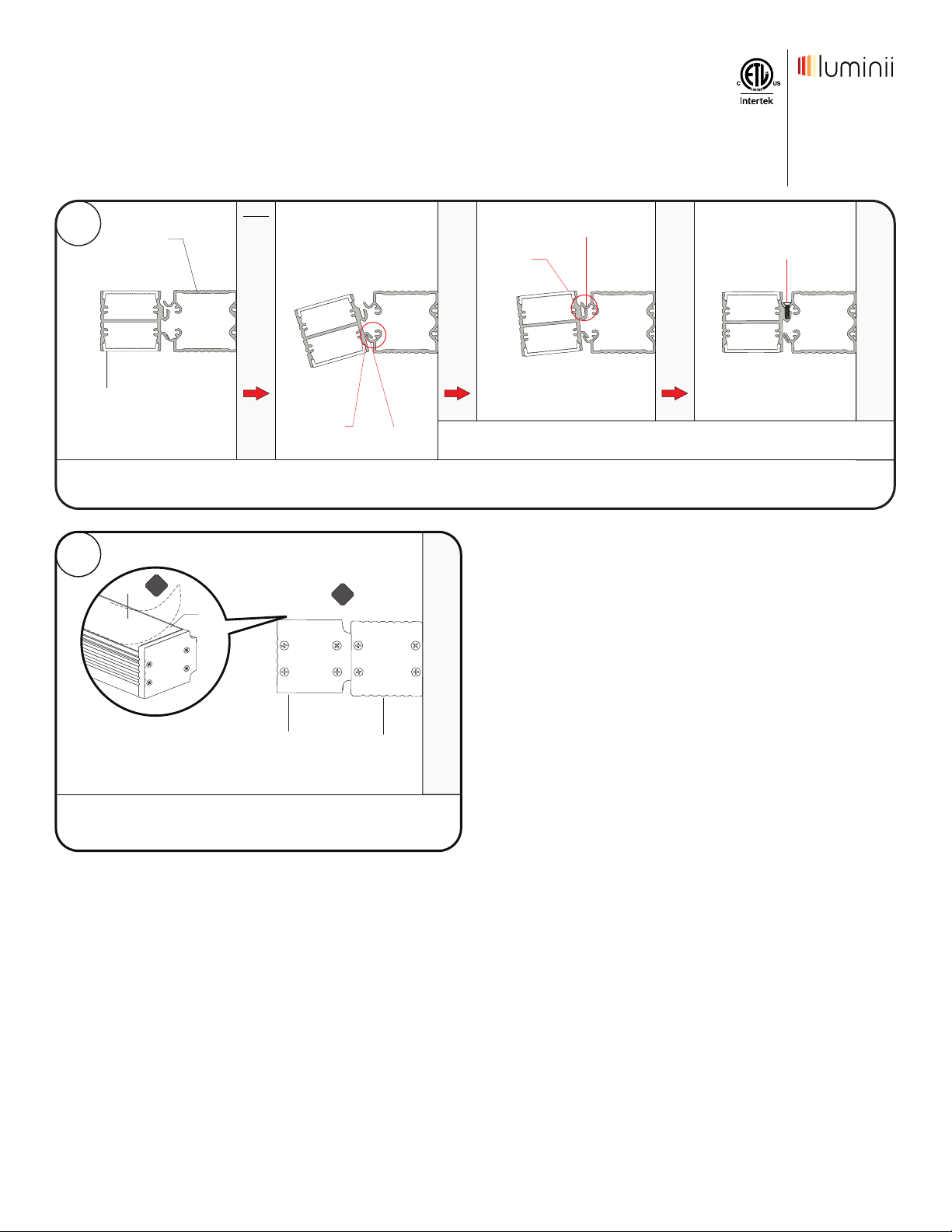
6.1 Insert the fixture lower flange into the mounting bracket lip. Then push the fixture threaded slot to the mounting bracket holes and secure using the
provided self tapping screws, refer to diagram above for reference.
wall
A B C D
lower
flange
bracket lip
threaded
slot
CERTAIN PARTS NOT SHOWN FOR CLARITY
mounting
bracket hole
7777 Merrimac Ave
Niles, IL 60714
T 224.333.6033
F 224.757.7557
[email protected]
www.luminii.com
self tapping
screw
7
7.1
film
lens
fixture
7.1 From the top & bottom of the fixture, remove the protective film
from both of the diffuser lens.
7.1
mounting
bracket
*LUMINII RESERVES THE RIGHTS TO CHANGE SPECIFICATION & INSTRUCTION WITHOUT NOTICE
REV1.1
 Loading...