

Page 1
ASSEMBLY AND INSTALLATION
INSTRUCTIONS
352-8543
TO AVOID RISK OF ELECTRICAL SHOCK, BE SURE TO SHUT OFF
WARNING:
NOTES: 1. Before installing, consult local electrical codes for wiring and grounding requirements.
2. Customer Service: 1-800-887-6326 (weekdays 9 a.m. – 5 p.m. CST)
3. READ AND SAVE THESE INSTRUCTIONS.
Warning: LED electronics can be damaged by electro static discharge (ESD)shock. Before
installation, discharge yourself by touching a grounded bare metal surface to remove this
hazard. To avoid damage, do not touch the LED module.
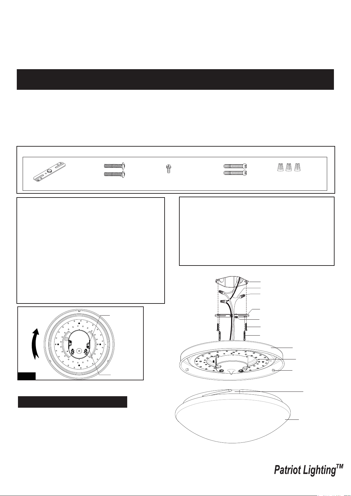
Hardware Package (included):
POWER BEFORE INSTALLING OR SERVICING THIS FIXTURE.
Mounting Strap (A)
Mounting Screw (B)
Green Grounding
Screw (C)
Important to Know:
1. If you are not familiar with state and local electrical
codes, it is recommended that you consult with a
qualified electrician.
2. This fixture requires a 120 VAC, 60 Hz power
source. Using non-replaceable LED bulb.
3. For general safety and to avoid any possible
damage to the sensor, be sure the power is
switched "off" before adjustment.
4. This sensor light has to be wired to its own switch.
Do not interconnect with others using the same
switch.
Maximum Wattage: 20 W
Working Temperature Range: 14°F ~ 122°F
Key Hole Slot
Long Screw (D)
Wire Nut (E)
Features:
1. Energy saving LED fixture.
2. Motion sensor: turns light ON automatically when
motion is detected and turns light OFF automatically
when motion stops.
3. The built-in motion sensor with 360° of detection
range saves energy and makes life more convenient.
4. In manual override mode, the light remains on for 6
hours.
Outlet Box
House Grounding Wire
Wire Nut (E)
Mounting Strap (A)
Green Grounding Screw (C)
Mounting Screw (B)
Long Screw (D)
Ceiling Pan
Fig.1
Long Screw
Installation Steps
Turn off the power at fuse or circuit box.
1. Remove the plastic shade from ceiling pan.
2. Attach the two long screws to the holes on the
mounting strap. Thread them in part way: 2 to 3
turns only.
3. Attach the mounting strap to the outlet box using two
mounting screws.
LED Module
Stud
Slot
Plastic Shade
Page 1/4
160526
Page 2

4. Pull out the source wires from the outlet box. Make wire connections using wire nuts as follows:
---Connect the hot wire (usually black insulation) from the fixture to the black wire from the power source.
---Connect the neutral wire (usually white insulation) from the fixture to the white wire from the power source.
---Attach the fixture grounding wire (usually green insulation or bare wire) to the mounting strap with the green
grounding screw, and then connect them to the house grounding wire with the wire nut.
Carefully put the wires back into the outlet box.
5. Attach the ceiling pan to the mounting strap by inserting two long screw heads into the key holes. Rotate the ceiling
pan until it is locked into place, and then tighten the long screws to secure it. (See Fig.1)
6. Attach the plastic shade back to the ceiling pan by aligning studs with slots, and turn it clockwise until it is locked in
place.
Turn on the power at fuse or circuit box
Function and Operation
Note: When power is first applied, the light will turn on. The sensor will take 15 seconds to warm up.
1. Auto Mode (daytime and nighttime operation)
● After warming up, the light enters into “AUTO” mode
automatically. When motion is detected, the light turns on
and stays on as long as motion continues. When the motion
is no longer detected, the light remains on for the
predetermined time you set (8s ~ 12min), and then turn off
automatically. (See Fig.3)
2. Manual Override (daytime and nighttime operation)
● Turn the wall switch “OFF” then turn it “ON” within 2 seconds,
the light remains on for 6 hours, and then return to “AUTO”
mode. To shift back to “AUTO” mode, turn the wall switch
“OFF” then turn it “ON” within 2 seconds again, or turn the
wall switch “OFF” and then waiting over 8 seconds before
turning it on again. (See Fig.2)
Note: To make sure the above functions operate properly,
always keep the wall switch in the “ON” position (including
the daytime).
Fig.2
Fig.3
3Ft
Manual Override Operation Diagram
Turn wall switch OFF-ON
Auto
Mode
12Ft
25Ft
within 2 Seconds
Turn wall switch OFF-ON
within 2 Seconds,
Or turn wall switch OFF and
then waiting 8 seconds
before turning ON
SENS
Manual
Override
Mode
6Min
8Sec
TIMER
12Min
Customization Options:
Shut-off Delay
● The shut-off delay is the length of time the light will stay at brightness after motion has ceased to be detected.
● You can set the shut-off delay by rotating the delay time knob arrow so it points to the desired time setting within
“TIME” range. To increase the shut-off delay, turn the knob clockwise. To decrease the shut-off delay, turn the
knob counterclockwise. (See Fig.3)
Detection range setting (sensitivity)
● Detection range is the term used to describe the diameter of the more or less circular detection zone produced on
the ground after mounting the sensor light at a height of 8.2 feet, turn the detection range control fully anti-clockwise
to select minimum detection range (approx.3 feet diameter), and fully clockwise to select maximum detection range
(approx. 25 feet diameter). (See Fig.3, Fig.4)
Fig.4
8.2'-11.5'
Height of installation8.2' ~ 11.5'
Min:3'
Max:25'
Sensing distance adjustment range
Sensing angle adjustment range
360º
Page 2/4
160526
Page 3

NOTE:
a. The above detection range is gained in the case of a person who is between 5.2 feet ~ 5.6 feet tall with middle figure
and moves at a speed of 3.3 feet ~4.9 feet/sec. If person’s stature, figure and moving speed change, the detection
range will also change. In different cases, the sensitivity of the lights has certain deviation.
b. When using this product, please adjust the sensitivity (detection range) to an appropriate value but the maximum to
avoid the abnormal reaction caused by the easy detection of the wrong motion by the blowing leaves & curtains,
small animals or the interference of power grid & electrical equipment. All the above mentioned will lead to the error
reaction. When the product does not work normally, please try to lower the sensitivity appropriately, and then test it.
Friendly reminder: When installing two or more microwaves together, you are required to keep 13.1feet one from
another, otherwise the interference among them will lead to error reaction.
c. For best performance, install fixture at least 9.6 feet above the ground. At such a height, the fixture will provide a
detection distance of up to 25 feet at 77 degrees Fahrenheit. (See Fig.4)
d. The sensor detects movement across a detection range of 360 degrees. (See Fig.4)
e. Do not mount the fixture near fans or other motion-inducing objects.
Troubleshooting
Fault Failure cause Solution
The load fails to work.
The load works all the time.
The load works when there is
no motion signal detected.
The load fails to work when
there is motion signal detected.
The power is off.
There is a continuous signal in the region of the detection.
The lamp isn't installed well so that sensor fails to
detect reliable signals.
Moving signal is detected by the sensor (movement
behind the wall, the movement of small objects, etc.)
The motion speed is too fast or the defined detection
area is too small.
Turn the power on.
Check the settings of the
detection area. Please adjust
detection range.
Re-adjust the installation place.
Check the settings of the
detection area. Please adjust
detection range.
Check the settings of the
detection area. Please adjust
detection range.
FCC Statement
1. This device complies with Part 15 of the FCC Rules. Operation is subject to the following two conditions:
(1) This device may not cause harmful interference.
(2) This device must accept any interference received, including interference that may cause undesired operation.
2. Changes or modifications not expressly approved by the party responsible for compliance could void the user's
authority to operate the equipment.
NOTE: The manufacturer is not responsible for any radio or TV interference caused by unauthorized modifications
to this equipment. Such modifications could void the user’s authority to operate the equipment.
NOTE: This equipment has been tested and found to comply with the limits for a Class B digital device, pursuant to
part 15 of the FCC Rules. These limits are designed to provide reasonable protection against harmful interference
in a residential installation.
This equipment generates uses and can radiate radio frequency energy and, if not installed and used in accordance
with the instructions, may cause harmful interference to radio communications. However, there is no guarantee that
interference will not occur in a particular installation. If this equipment does cause harmful interference to radio or
television reception, which can be determined by turning the equipment off and on, the user is encouraged to try to
correct the interference by one or more of the following measures:
- Reorient or relocate the receiving antenna.
- Increase the separation between the equipment and receiver.
- Connect the equipment into an outlet on a circuit different from that to which the receiver is connected.
- Consult the dealer or an experienced radio/TV technician for help
This equipment complies with FCC radiation exposure limits set forth for an uncontrolled environment. This equipment
should be installed and operated with minimum distance of 20 cm between the radiator and your body.
Page 3/4
160526
Page 4

The following parts are available for re-order if damaged or missing. Call us toll-free at 1-800-887-6326
Spare Parts List:
Assembly Kit
5559MM (1 SET)
Mounting Strap (A)
Long Screw (D)
Mounting Screw (B)
Wire Nut (E)
Green Grounding
Screw (C)
Plastic Shade
9817PS
5-YEAR LIMITED WARRANTY:
This Patriot Lighting fixture carries a limited warranty against defects in material or workmanship. If the Patriot Lighting
product fails at any time within five (5) years after the original date of sale due to defects in material or workmanship,
return the product to Menards with the original sales receipt. At its discretion, Patriot Lighting will replace the defective
fixture with the same or similar fixture or issue a refund. This warranty and any implied warranty (including but not limited
to any implied warranty of merchantability or fitness for a particular purpose) does not cover glass globes, light bulbs and
other expendable items. This warranty excludes coverage of finish or color against tarnishing, flaking, and discoloration.
If the original purchaser ceases to own the Patriot Lighting product this warranty and any implied warranty will be void.
This warranty does not cover damage caused by misuse or abuse, including but not limited to improper installation,
improper usage, accident, negligence, unauthorized repair, unauthorized modifications, or unauthorized maintenance of
the fixture. This warranty does not include reimbursement for inconvenience, installation, setup time, returned shipping
charges or defects, losses, labor, injuries to personal property.
This warranty gives the consumer specific legal rights, and the consumer may have other rights which vary from state to
state. The seller’s employees are not qualified to advise on the use of the fixture. Any oral representations made will
not be binding on seller or its employees.
For questions regarding this product, call toll-free at 1-800-887-6326.
Page 4/4
160526
 Loading...