

Page 1
Lum/nex
®
International English Version
Luminex 100™ IS
User Manual Version 2.1
Page 2

© LUMINEX CORPORATION, 2001-2003. All rights reserved. No part of this publication may be reproduced,
transmitted, transcribed, or translated into any language or computer language, in any form or by any means
without prior express, written consent of:
LUMINEX CORPORATION
12212 Technology Boulevard
Austin, Texas 78727-6115
U.S.A.
Voice: (512) 219-8020
Fax: (512) 219-5195
Luminex
Luminex Corporation (Luminex) reserves the right to modify its products and services at any time. This guide
is subject to change without notice. Although prepared to ensure accuracy, Luminex assumes no liability for
errors or omissions, or for any damages resulting from the application or use of this information.
® 100™ IS User Manual Version 2.1
REF
PN 89-00002-00-070 Rev. A
CN-M011-01
January 2004
REP
EC
Paul. A. Rowden
33 Stapleford Road
Middlesbrough
Cleveland TS39ES
England
(TQMUK@aol.com)
The following are trademarks of Luminex: Luminex 100, Luminex 100 IS, LabMAP, xMAP,
LumAvidin, Luminex XYP, Luminex FlexMAP, and Luminex SD. All other trademarks, including Windows,
Cheminert, Pentium, and Dell
The Luminex 100 IS software uses the VideoSoft
ActiveX controls, which are copyrighted by VideoSoft, 2001.
The contents of this manual and the associated Luminex software are the property of Luminex and are
copyrighted. Except as specified in the End User License Agreement, any reproduction in whole or in part is
strictly prohibited.
are trademarks of their respective companies.
® VsFlexGrid Pro 7.0, VsPrinter 7.0, and VsView 3.0
Page 3

End-User License Agreement (EULA) for Luminex® Software
This Luminex End-User License Agreement (“EULA”) is a legal agreement between you (either an individual
or a single entity, also referred herein as “you”) the end-user and Luminex Corporation (“Luminex”) regarding
the use of the Luminex software product identified above, which includes computer software and online or
electronic documentation and may include associated media and printed materials (if any) (“SOFTWARE
PRODUCT” or “SOFTWARE”).
The SOFTWARE PRODUCT is protected by copyright laws and international copyright treaties, as well as
other intellectual property laws and treaties. The SOFTWARE PRODUCT is licensed, not sold.
1. GRANT OF LICENSE. Subject to the terms and conditions of this EULA, Luminex hereby grants to you a
nonexclusive, nontransferable, nonassignable license (without right to sublicense) under Luminex’s
copyrights and trade secrets to use the SOFTWARE PRODUCT on a hardware platform purchased from
Luminex pursuant to Luminex’s terms and conditions of sale. You may make one (1) copy of the
SOFTWARE PRODUCT for backup or archival purposes only. Although no rights or licenses under any
of Luminex's patents are granted by or shall be implied from the license of the SOFTWARE or the sale of
Luminex instrumentation to you, the purchaser, you may obtain a license under Luminex’s patents, if any,
to use this unit of Luminex instrumentation with fluorescently labeled microsphere beads authorized by
Luminex by purchasing such beads from Luminex or an authorized Luminex reseller.
2. RESTRICTIONS.
• You must maintain all proprietary notices on all copies of the SOFTWARE PRODUCT.
• You may not distribute copies of the SOFTWARE PRODUCT to third parties.
• You may not reverse-engineer, decompile, disassemble, or otherwise attempt to derive source
code from the SOFTWARE PRODUCT.
• You may not copy (other than one backup or archival copy), distribute, sublicense, rent, lease,
transfer or grant any rights in or to all or any portion of the SOFTWARE PRODUCT.
• You must comply with all applicable laws regarding the use of the SOFTWARE PRODUCT.
• You may not modify or prepare derivative works of the SOFTWARE PRODUCT.
• You may not use the SOFTWARE PRODUCT in a computer-based service business or publicly
display visual output of the SOFTWARE PRODUCT.
• You may not transmit the SOFTWARE PRODUCT over a network, by telephone, or
electronically by any means.
3. TERM AND TERMINATION. Your rights under this EULA are effective until termination. You may
terminate this EULA at any time by destroying the SOFTWARE PRODUCT, including all computer
programs and documentation, and erasing any copies residing on your computer equipment. Luminex
may terminate this EULA upon thirty (30) days written notice to you. Your rights under this EULA
automatically terminate without further action on the part of Luminex if you do not comply with any of the
terms or conditions of this EULA. Upon any termination of this EULA, you agree to destroy the
SOFTWARE PRODUCT and erase any copies residing on your computer equipment.
4. RIGHTS IN SOFTWARE. All rights and title in and to the SOFTWARE PRODUCT and any copies
thereof are owned by Luminex or its suppliers. This EULA is not a sale and does not transfer to you any
title or ownership interest in or to the SOFTWARE or any patent, copyright, trade secret, trade name,
trademark or other intellectual property right therein. You shall not remove, alter, or obscure any
proprietary notices contained on or within the SOFTWARE and shall reproduce such notices on any
back-up copy of the SOFTWARE. All title and intellectual property rights in and to the content which may
be accessed through use of the SOFTWARE PRODUCT is the property of the respective content owner
and may be protected by applicable copyright or other intellectual property laws and treaties. This EULA
grants you no rights to use such content.
Page 4

5. EXPORT RESTRICTIONS. You agree that you will not export or re-export the SOFTWARE PRODUCT
to any country, person, entity, or end-user subject to U.S.A. export restrictions. You hereby warrant no
state or federal agency has suspended, revoked, or denied your export privileges.
6. NO WARRANTY. THE SOFTWARE PRODUCT IS LICENSED “AS IS.” ANY USE OF THE SOFTWARE
PRODUCT IS AT YOUR OWN RISK. THE SOFTWARE PRODUCT IS PROVIDED FOR USE ONLY
WITH LUMINEX PRODUCTS. TO THE MAXIMUM EXTENT PERMITTED BY APPLICABLE LAW,
LUMINEX AND ITS SUPPLIERS DISCLAIM ALL WARRANTIES, EITHER EXPRESS OR IMPLIED,
INCLUDING, BUT NOT LIMITED TO, IMPLIED WARRANTIES OF MERCHANTABILITY, FITNESS FOR
A PARTICULAR PURPOSE, AND NONINFRINGEMENT.
7. LIMITATION OF LIABILITY. IN NO EVENT SHALL LUMINEX OR ITS SUPPLIERS BE LIABLE FOR
ANY SPECIAL, INCIDENTAL, INDIRECT, OR CONSEQUENTIAL DAMAGES WHATSOEVER
(INCLUDING, WITHOUT LIMITATION, DAMAGES FOR LOSS OF BUSINESS PROFITS, BUSINESS
INTERRUPTION, LOSS OF BUSINESS INFORMATION, OR ANY OTHER PECUNIARY LOSS)
ARISING OUT OF THE USE OF OR INABILITY TO USE THE SOFTWARE PRODUCT, EVEN IF
LUMINEX HAS BEEN ADVISED OF THE POSSIBILITY OF SUCH DAMAGES.
MISCELLANEOUS. This EULA is governed by the laws of the State of Texas, U.S.A., without reference to
conflicts of laws principles. You shall not assign or sublicense or otherwise transfer the rights or license
granted hereunder, by agreement or by operation of law, without the prior written consent of Luminex, and all
assignments in violation of this prohibition shall be null and void. This EULA is the complete and exclusive
agreement of Luminex and you and supersedes all other communications, oral or written, relating to the subject matter hereof. No change to this EULA shall be valid unless in writing and signed by the party against
whom enforcement is sought. The waiver or failure of Luminex or you to exercise in any respect any right or
rights provided for herein shall not be deemed a waiver of any further right hereunder. If any provision of this
EULA is held unenforceable, the remainder of this EULA will continue in full force and effect.
EULA PN: 89-30000-00-070
Page 5

Contents
Introduction 1-1
About This Manual . . . . . . . . . . . . . . . . . . . . . . . . . . . . . . . . . . . . .1-1
Intended Use . . . . . . . . . . . . . . . . . . . . . . . . . . . . . . . . . . . . . . . . . .1-1
What is the Luminex 100 IS? . . . . . . . . . . . . . . . . . . . . . . . . . . . . . 1-1
Customer Support . . . . . . . . . . . . . . . . . . . . . . . . . . . . . . . . . . . . . . 1-2
Safety 2-1
Symbols. . . . . . . . . . . . . . . . . . . . . . . . . . . . . . . . . . . . . . . . . . . . . . 2-1
Safety Precautions . . . . . . . . . . . . . . . . . . . . . . . . . . . . . . . . . . . . . . 2-2
Electrical . . . . . . . . . . . . . . . . . . . . . . . . . . . . . . . . . . . . . . . . . . 2-2
Luminex 100 IS Laser Classification . . . . . . . . . . . . . . . . . . . . 2-5
Luminex 100 Analyzer Laser . . . . . . . . . . . . . . . . . . . . . . . . . . 2-5
Bar Code Reader Laser . . . . . . . . . . . . . . . . . . . . . . . . . . . . . . . 2-7
Mechanical . . . . . . . . . . . . . . . . . . . . . . . . . . . . . . . . . . . . . . . . 2-7
Biological . . . . . . . . . . . . . . . . . . . . . . . . . . . . . . . . . . . . . . . . .2-8
Heat. . . . . . . . . . . . . . . . . . . . . . . . . . . . . . . . . . . . . . . . . . . . . . 2-8
Blue Indicator Light . . . . . . . . . . . . . . . . . . . . . . . . . . . . . . . . . 2-8
Decontamination of the Luminex 100 IS for Return Shipment . . . 2-9
Basic Concepts 3-1
Background Information . . . . . . . . . . . . . . . . . . . . . . . . . . . . . . . . .3-1
Fluidics . . . . . . . . . . . . . . . . . . . . . . . . . . . . . . . . . . . . . . . . . . . . . . 3-1
Excitation. . . . . . . . . . . . . . . . . . . . . . . . . . . . . . . . . . . . . . . . . . . . . 3-1
xMAP Microspheres . . . . . . . . . . . . . . . . . . . . . . . . . . . . . . . . . . . . 3-2
Software Overview . . . . . . . . . . . . . . . . . . . . . . . . . . . . . . . . . . . . . 3-2
Installation 4-1
Assemble and Power the Luminex 100 IS System . . . . . . . . . . . . . 4-1
Hardware Setup. . . . . . . . . . . . . . . . . . . . . . . . . . . . . . . . . . . . . 4-1
Connect the Luminex 100 Analyzer and XYP Instrument 4-1
Install or Replace the XYP Instrument Sample Probe . . . . . . . 4-6
Install the XYP Instrument Reservoir . . . . . . . . . . . . . . . . 4-9
Install the XYP Instrument Heater Block (Optional). . . . . 4-9
Adjust the Sample Probe Vertical Height . . . . . . . . . . . . 4-10
Initialization . . . . . . . . . . . . . . . . . . . . . . . . . . . . . . . . . . . . . . 4-12
Initialize the PC . . . . . . . . . . . . . . . . . . . . . . . . . . . . . . . . 4-12
Initialize the Luminex 100 IS Software . . . . . . . . . . . . . . 4-12
Installation Drawing . . . . . . . . . . . . . . . . . . . . . . . . . . . . . . . . . . . 4-13
PN 89-00002-00-070 Rev. A i
Page 6

Luminex 100 IS User Manual Version 2.1 xMAP Technology
The System 5-1
Theory of Operation . . . . . . . . . . . . . . . . . . . . . . . . . . . . . . . . . . . . 5-1
Hardware . . . . . . . . . . . . . . . . . . . . . . . . . . . . . . . . . . . . . . . . . . . . 5-2
xMAP Reagents . . . . . . . . . . . . . . . . . . . . . . . . . . . . . . . . . . . . . . . 5-2
Required Laboratory Reagents. . . . . . . . . . . . . . . . . . . . . . . . . . . . 5-3
Software . . . . . . . . . . . . . . . . . . . . . . . . . . . . . . . . . . . . . . . . . . . . . 5-3
Luminex 100 IS Performance Specifications. . . . . . . . . . . . . . . . . 5-3
Speed . . . . . . . . . . . . . . . . . . . . . . . . . . . . . . . . . . . . . . . . . . . . 5-3
Accuracy and Precision . . . . . . . . . . . . . . . . . . . . . . . . . . . . . . 5-4
Sensitivity . . . . . . . . . . . . . . . . . . . . . . . . . . . . . . . . . . . . . . . . 5-4
Capacity . . . . . . . . . . . . . . . . . . . . . . . . . . . . . . . . . . . . . . . . . . 5-4
Luminex 100 Analyzer . . . . . . . . . . . . . . . . . . . . . . . . . . . . . . . . . . 5-5
General. . . . . . . . . . . . . . . . . . . . . . . . . . . . . . . . . . . . . . . . . . . 5-5
Optics . . . . . . . . . . . . . . . . . . . . . . . . . . . . . . . . . . . . . . . . . . . . 5-5
Fluidics. . . . . . . . . . . . . . . . . . . . . . . . . . . . . . . . . . . . . . . . . . . 5-5
Electronics . . . . . . . . . . . . . . . . . . . . . . . . . . . . . . . . . . . . . . . . 5-6
XYP Instrument . . . . . . . . . . . . . . . . . . . . . . . . . . . . . . . . . . . . . . . 5-6
General. . . . . . . . . . . . . . . . . . . . . . . . . . . . . . . . . . . . . . . . . . . 5-6
PC Specifications . . . . . . . . . . . . . . . . . . . . . . . . . . . . . . . . . . . . . . 5-6
Recommended Additional Equipment. . . . . . . . . . . . . . . . . . . 5-7
Uninterruptible Power Supply (UPS) . . . . . . . . . . . . . . . . 5-7
Surge Protector . . . . . . . . . . . . . . . . . . . . . . . . . . . . . . . . . 5-7
Printer . . . . . . . . . . . . . . . . . . . . . . . . . . . . . . . . . . . . . . . . 5-7
Bar Code Labels . . . . . . . . . . . . . . . . . . . . . . . . . . . . . . . . 5-7
Vortex . . . . . . . . . . . . . . . . . . . . . . . . . . . . . . . . . . . . . . . . 5-7
Bath Sonicator . . . . . . . . . . . . . . . . . . . . . . . . . . . . . . . . . . 5-7
System Overview . . . . . . . . . . . . . . . . . . . . . . . . . . . . . . . . . . . . . . 5-7
Electronics . . . . . . . . . . . . . . . . . . . . . . . . . . . . . . . . . . . . . . . . 5-8
Power Input Module . . . . . . . . . . . . . . . . . . . . . . . . . . . . . 5-8
P1 Communications Port (SB9-PIN) . . . . . . . . . . . . . . . . 5-8
Luminex 100 Analyzer Ventilation Filter . . . . . . . . . . . . . 5-8
XYP Instrument Ventilation Filter . . . . . . . . . . . . . . . . . . 5-8
Fluidics. . . . . . . . . . . . . . . . . . . . . . . . . . . . . . . . . . . . . . . . . . . 5-9
Sample Arm. . . . . . . . . . . . . . . . . . . . . . . . . . . . . . . . . . . . 5-9
XYP Instrument Sample Probe . . . . . . . . . . . . . . . . . . . . 5-10
Cheminert® Fitting . . . . . . . . . . . . . . . . . . . . . . . . . . . . . 5-10
Access Doors. . . . . . . . . . . . . . . . . . . . . . . . . . . . . . . . . . 5-11
Air Intake Filter . . . . . . . . . . . . . . . . . . . . . . . . . . . . . . . . 5-11
Syringe. . . . . . . . . . . . . . . . . . . . . . . . . . . . . . . . . . . . . . . 5-12
Sheath Filter . . . . . . . . . . . . . . . . . . . . . . . . . . . . . . . . . . 5-12
Air, Waste, and Sheath Fluid Connectors . . . . . . . . . . . . 5-13
Sheath Fluid Container (not shown) . . . . . . . . . . . . . . . . 5-13
Waste Fluid Container (not shown). . . . . . . . . . . . . . . . . 5-13
Optical . . . . . . . . . . . . . . . . . . . . . . . . . . . . . . . . . . . . . . . . . . 5-14
xMAP Reagents . . . . . . . . . . . . . . . . . . . . . . . . . . . . . . . . . . . 5-14
ii PN 89-00002-00-070 Rev. A
Page 7

xMAP Technology
System Calibration 6-1
Software Tour 7-1
System Calibration and Verification Overview . . . . . . . . . . . . . . . 6-1
Calibrate the System . . . . . . . . . . . . . . . . . . . . . . . . . . . . . . . . . 6-2
Run System Calibrators . . . . . . . . . . . . . . . . . . . . . . . . . . .6-2
Run System Controls . . . . . . . . . . . . . . . . . . . . . . . . . . . . .6-4
Calibration and System Control Trend Reports . . . . . . . . . . . . 6-5
Print or View a Calibration or System Control
Trend Report . . . . . . . . . . . . . . . . . . . . . . . . . . . . . . . . . . . 6-6
Luminex 100 IS 2.1 Software . . . . . . . . . . . . . . . . . . . . . . . . . . . . . 7-1
Getting Started . . . . . . . . . . . . . . . . . . . . . . . . . . . . . . . . . . . . . 7-1
Enter xMAP Calibration and Control Targets For the First
Time . . . . . . . . . . . . . . . . . . . . . . . . . . . . . . . . . . . . . . . . . .7-2
IS 2.1 Main Screen . . . . . . . . . . . . . . . . . . . . . . . . . . . . . . . . . . . . . 7-3
Menu Bar . . . . . . . . . . . . . . . . . . . . . . . . . . . . . . . . . . . . . . . . . 7-4
Enter General Information . . . . . . . . . . . . . . . . . . . . . . . . . 7-4
Enter Company Information. . . . . . . . . . . . . . . . . . . . . . . .7-5
Toolbar . . . . . . . . . . . . . . . . . . . . . . . . . . . . . . . . . . . . . . . . . . .7-6
Status Bar . . . . . . . . . . . . . . . . . . . . . . . . . . . . . . . . . . . . . . . . . 7-6
Status Communication . . . . . . . . . . . . . . . . . . . . . . . . . . . . . . . 7-8
Tabs. . . . . . . . . . . . . . . . . . . . . . . . . . . . . . . . . . . . . . . . . . . . . . 7-9
Home Tab . . . . . . . . . . . . . . . . . . . . . . . . . . . . . . . . . . . . . . . . . . .7-10
Favorites Section. . . . . . . . . . . . . . . . . . . . . . . . . . . . . . . . . . . 7-10
Add Templates To Favorites . . . . . . . . . . . . . . . . . . . . . . 7-11
Add Commands to Favorites . . . . . . . . . . . . . . . . . . . . . . 7-12
Remove Items From Favorites . . . . . . . . . . . . . . . . . . . . .7-13
Data Acquisition Categories . . . . . . . . . . . . . . . . . . . . . . . . . . 7-13
Run Batch Tab. . . . . . . . . . . . . . . . . . . . . . . . . . . . . . . . . . . . . . . . 7-14
Microtiter Plate . . . . . . . . . . . . . . . . . . . . . . . . . . . . . . . . . . . . 7-14
Reservoir. . . . . . . . . . . . . . . . . . . . . . . . . . . . . . . . . . . . . . . . . 7-15
Temperature and Pressure Gauges . . . . . . . . . . . . . . . . . . . . . 7-15
Set the XYP Instrument Heater Temperature . . . . . . . . .7-16
Command List. . . . . . . . . . . . . . . . . . . . . . . . . . . . . . . . . . . . . 7-16
Maintenance Tab . . . . . . . . . . . . . . . . . . . . . . . . . . . . . . . . . . . . . . 7-18
As-Needed Maintenance Operations . . . . . . . . . . . . . . . . . . . 7-18
Warm Up the System . . . . . . . . . . . . . . . . . . . . . . . . . . . .7-20
Prime the System . . . . . . . . . . . . . . . . . . . . . . . . . . . . . . .7-21
Backflush the System . . . . . . . . . . . . . . . . . . . . . . . . . . . . 7-21
Alcohol Flush the System . . . . . . . . . . . . . . . . . . . . . . . . 7-22
Sanitize the System . . . . . . . . . . . . . . . . . . . . . . . . . . . . .7-22
Wash the System . . . . . . . . . . . . . . . . . . . . . . . . . . . . . . . 7-23
Drain the System . . . . . . . . . . . . . . . . . . . . . . . . . . . . . . . 7-24
Soak the Probe . . . . . . . . . . . . . . . . . . . . . . . . . . . . . . . . .7-24
Run Self Diagnostics . . . . . . . . . . . . . . . . . . . . . . . . . . . .7-26
View Failed Self-Diagnostic Details . . . . . . . . . . . . . . . . 7-27
XYP Commands . . . . . . . . . . . . . . . . . . . . . . . . . . . . . . . . . . . . . . 7-27
PN 89-00002-00-070 Rev. A iii
Page 8

Luminex 100 IS User Manual Version 2.1 xMAP Technology
Calibration and Verification . . . . . . . . . . . . . . . . . . . . . . . . . 7-27
Set Well Locations for Calibration and Controls . . . . . . 7-27
Enter System Calibration Targets . . . . . . . . . . . . . . . . . . 7-27
Enter System Control Targets . . . . . . . . . . . . . . . . . . . . . 7-29
Eject and Retract the XYP Instrument Plate Holder . . . . 7-30
Lower and Raise the Sample Probe. . . . . . . . . . . . . . . . . 7-30
Diagnostics Tab . . . . . . . . . . . . . . . . . . . . . . . . . . . . . . . . . . . . . . 7-30
System Monitor . . . . . . . . . . . . . . . . . . . . . . . . . . . . . . . . . . . 7-31
Detailed Sample Progress . . . . . . . . . . . . . . . . . . . . . . . . . . . 7-32
Message Log . . . . . . . . . . . . . . . . . . . . . . . . . . . . . . . . . . . . . 7-32
Error Messages in the Message Log . . . . . . . . . . . . . . . . . . . 7-33
Batches . . . . . . . . . . . . . . . . . . . . . . . . . . . . . . . . . . . . . . . . . . . . . 7-34
Templates. . . . . . . . . . . . . . . . . . . . . . . . . . . . . . . . . . . . . . . . 7-34
Import a Template . . . . . . . . . . . . . . . . . . . . . . . . . . . . . . 7-34
Lots . . . . . . . . . . . . . . . . . . . . . . . . . . . . . . . . . . . . . . . . . . . . 7-35
Create New Lots . . . . . . . . . . . . . . . . . . . . . . . . . . . . . . . 7-35
Update Lot Information. . . . . . . . . . . . . . . . . . . . . . . . . . 7-37
Import Lots To Existing Templates. . . . . . . . . . . . . . . . . 7-38
Export Lots . . . . . . . . . . . . . . . . . . . . . . . . . . . . . . . . . . . 7-38
Batch Commands. . . . . . . . . . . . . . . . . . . . . . . . . . . . . . . . . . 7-39
Create a New Batch. . . . . . . . . . . . . . . . . . . . . . . . . . . . . 7-39
Open a Batch . . . . . . . . . . . . . . . . . . . . . . . . . . . . . . . . . . 7-42
Delete a Batch . . . . . . . . . . . . . . . . . . . . . . . . . . . . . . . . . 7-43
Create a
Multi-Batch . . . . . . . . . . . . . . . . . . . . . . . . . . . . . . . . . . . 7-43
Process a Multi-Batch . . . . . . . . . . . . . . . . . . . . . . . . . . . 7-46
Process Multiple Plates in a Batch . . . . . . . . . . . . . . . . . 7-46
Scan in New Samples with the Barcode Reader . . . . . . . 7-49
Add a Patient List to a Batch or Multi-Batch . . . . . . . . . 7-49
Establish Where to Begin Acquiring Data . . . . . . . . . . . 7-52
Change Where to Begin Acquiring Data in
Multi-Batches . . . . . . . . . . . . . . . . . . . . . . . . . . . . . . . . . 7-52
Assign Dilution Factors to Samples . . . . . . . . . . . . . . . . 7-52
Start a Plate . . . . . . . . . . . . . . . . . . . . . . . . . . . . . . . . . . . 7-53
Pause a Batch. . . . . . . . . . . . . . . . . . . . . . . . . . . . . . . . . . 7-54
Resume Acquisition . . . . . . . . . . . . . . . . . . . . . . . . . . . . 7-54
Cancel a Command . . . . . . . . . . . . . . . . . . . . . . . . . . . . . 7-54
Cancel Acquisition . . . . . . . . . . . . . . . . . . . . . . . . . . . . . 7-54
Analyze Batches and Multi-Batches . . . . . . . . . . . . . . . . . . . . . . 7-55
Begin Data Reduction Immediately Upon Completing
Acquisition . . . . . . . . . . . . . . . . . . . . . . . . . . . . . . . . . . . 7-55
Analyze Data From Processed Batches. . . . . . . . . . . . . . 7-55
View Detailed Analyses For Selected Tests . . . . . . . . . . 7-56
Errors Tab . . . . . . . . . . . . . . . . . . . . . . . . . . . . . . . . . . . . . . . 7-58
View Detailed Error Information . . . . . . . . . . . . . . . . . . 7-58
Standards Tab. . . . . . . . . . . . . . . . . . . . . . . . . . . . . . . . . . . . . 7-58
Samples Tab. . . . . . . . . . . . . . . . . . . . . . . . . . . . . . . . . . . . . . 7-59
Perform Batch Data Reduction . . . . . . . . . . . . . . . . . . . . 7-60
Data Output . . . . . . . . . . . . . . . . . . . . . . . . . . . . . . . . . . . . . . . . . 7-60
iv PN 89-00002-00-070 Rev. A
Page 9

xMAP Technology
Maintenance and Cleaning 8-1
Reports . . . . . . . . . . . . . . . . . . . . . . . . . . . . . . . . . . . . . . . . . .7-60
Export Data. . . . . . . . . . . . . . . . . . . . . . . . . . . . . . . . . . . . . . .7-63
Database Management . . . . . . . . . . . . . . . . . . . . . . . . . . . . . . . . . 7-64
Back Up the Database. . . . . . . . . . . . . . . . . . . . . . . . . . . . . . . 7-64
Erase Data from the Database. . . . . . . . . . . . . . . . . . . . . . . . . 7-64
Restore a Previously Saved Database. . . . . . . . . . . . . . . . . . . 7-65
Edit Menu . . . . . . . . . . . . . . . . . . . . . . . . . . . . . . . . . . . . . . . . . . .7-66
Copy Information From Your Batch . . . . . . . . . . . . . . . . . . . 7-66
Paste Information From Your Batch. . . . . . . . . . . . . . . . . . . . 7-66
Clear Your Batch From the System . . . . . . . . . . . . . . . . . . . .7-66
Clear the Message Log . . . . . . . . . . . . . . . . . . . . . . . . . . . . . .7-66
Help Menu. . . . . . . . . . . . . . . . . . . . . . . . . . . . . . . . . . . . . . . . . . . 7-67
Open System Help . . . . . . . . . . . . . . . . . . . . . . . . . . . . . . . . .7-67
Display About the Device Information. . . . . . . . . . . . . . . . . . 7-67
Display About the IS Software Information . . . . . . . . . . . . . . 7-68
Shut Down the Luminex 100 Analyzer. . . . . . . . . . . . . . . . . . . . .7-69
Exit the Luminex 100 IS Software . . . . . . . . . . . . . . . . . . . . . . . . 7-71
Daily . . . . . . . . . . . . . . . . . . . . . . . . . . . . . . . . . . . . . . . . . . . . . . . . 8-1
Before Running Samples . . . . . . . . . . . . . . . . . . . . . . . . . . . . . 8-1
After Running Samples. . . . . . . . . . . . . . . . . . . . . . . . . . . . . . .8-2
Weekly. . . . . . . . . . . . . . . . . . . . . . . . . . . . . . . . . . . . . . . . . . . . . . . 8-2
Visual Inspection . . . . . . . . . . . . . . . . . . . . . . . . . . . . . . . . . . .8-2
Monthly . . . . . . . . . . . . . . . . . . . . . . . . . . . . . . . . . . . . . . . . . . . . . . 8-2
Clean the Sample Probe . . . . . . . . . . . . . . . . . . . . . . . . . . . . . .8-2
Clean Exterior Surfaces . . . . . . . . . . . . . . . . . . . . . . . . . . . . . . 8-2
Calibration and System Controls . . . . . . . . . . . . . . . . . . . . . . .8-3
Semi-Annually. . . . . . . . . . . . . . . . . . . . . . . . . . . . . . . . . . . . . . . . . 8-3
Luminex 100 Analyzer Air Intake Filter . . . . . . . . . . . . . . . . . 8-3
XYP Instrument Air Intake Filter . . . . . . . . . . . . . . . . . . . . . . . 8-4
Syringe Seal . . . . . . . . . . . . . . . . . . . . . . . . . . . . . . . . . . . . . . . 8-6
Luminex 100 Analyzer Ventilation Filter. . . . . . . . . . . . . . . . . 8-7
Annually . . . . . . . . . . . . . . . . . . . . . . . . . . . . . . . . . . . . . . . . . . . . . 8-8
Sheath Filter . . . . . . . . . . . . . . . . . . . . . . . . . . . . . . . . . . . . . . . 8-8
As Required. . . . . . . . . . . . . . . . . . . . . . . . . . . . . . . . . . . . . . . . . . . 8-9
Sheath and Waste Fluids. . . . . . . . . . . . . . . . . . . . . . . . . . . . . . 8-9
Refill the Sheath Fluid Container. . . . . . . . . . . . . . . . . . . . 8-9
Empty the Waste Container . . . . . . . . . . . . . . . . . . . . . . . .8-9
Fuses . . . . . . . . . . . . . . . . . . . . . . . . . . . . . . . . . . . . . . . . . . . . 8-10
Sample Arm Vertical Height . . . . . . . . . . . . . . . . . . . . . . . . . 8-11
Accessories . . . . . . . . . . . . . . . . . . . . . . . . . . . . . . . . . . . . . . . 8-11
Maintenance Log. . . . . . . . . . . . . . . . . . . . . . . . . . . . . . . . . . . . . . 8-13
PN 89-00002-00-070 Rev. A v
Page 10

Luminex 100 IS User Manual Version 2.1 xMAP Technology
Troubleshooting 9-1
Troubleshooting the Luminex 100 IS. . . . . . . . . . . . . . . . . . . . . . . 9-1
Problem Diagnosis. . . . . . . . . . . . . . . . . . . . . . . . . . . . . . . . . . 9-1
Verify the System With System Controls . . . . . . . . . . . . . 9-2
Luminex 100 Analyzer Fails Calibration. . . . . . . . . . . . . . . . . 9-3
Luminex 100 Analyzer Fails System Controls . . . . . . . . . . . . 9-3
Failure During Self-Diagnostics Tests. . . . . . . . . . . . . . . . . . . 9-4
System Error Messages . . . . . . . . . . . . . . . . . . . . . . . . . . . . . . . . . 9-5
Unknown Diagnostic Error . . . . . . . . . . . . . . . . . . . . . . . . . . . 9-5
APD Temperature Range Exceeded . . . . . . . . . . . . . . . . . . . . 9-5
XYP Instrument Heater Stability Range Exceeded . . . . . . . . . 9-5
Low Voltage Detected . . . . . . . . . . . . . . . . . . . . . . . . . . . . . . . 9-5
Runtime Sheath Pressure Out of Limits (Too High) . . . . . . . . 9-5
Runtime Sheath Pressure Out of Limits (Too Low) . . . . . . . . 9-5
Low Laser Power Detected . . . . . . . . . . . . . . . . . . . . . . . . . . . 9-6
Command Encountered Time Out Error . . . . . . . . . . . . . . . . . 9-6
System Error States . . . . . . . . . . . . . . . . . . . . . . . . . . . . . . . . . . . . 9-6
Disconnected . . . . . . . . . . . . . . . . . . . . . . . . . . . . . . . . . . . . . . 9-6
Locked Out. . . . . . . . . . . . . . . . . . . . . . . . . . . . . . . . . . . . . . . . 9-6
Refill Sheath. . . . . . . . . . . . . . . . . . . . . . . . . . . . . . . . . . . . . . . 9-6
Running: Sheath Empty . . . . . . . . . . . . . . . . . . . . . . . . . . . . . . 9-6
Sample Error Messages . . . . . . . . . . . . . . . . . . . . . . . . . . . . . . . . . 9-6
Insufficient Bead Count . . . . . . . . . . . . . . . . . . . . . . . . . . . . . . 9-7
Temperature Divergence from Calibration Temperature . . . . 9-7
Failed Control in Batch . . . . . . . . . . . . . . . . . . . . . . . . . . . . . . 9-7
Failed Curve Fit . . . . . . . . . . . . . . . . . . . . . . . . . . . . . . . . . . . . 9-7
Sample High/Low . . . . . . . . . . . . . . . . . . . . . . . . . . . . . . . . . . 9-8
Failed Standard in Batch . . . . . . . . . . . . . . . . . . . . . . . . . . . . . 9-8
Sample Timed Out . . . . . . . . . . . . . . . . . . . . . . . . . . . . . . . . . . 9-8
Sample Empty Detected. . . . . . . . . . . . . . . . . . . . . . . . . . . . . . 9-9
Unknown Formula Failure. . . . . . . . . . . . . . . . . . . . . . . . . . . . 9-9
Luminex 100 Analyzer Problems. . . . . . . . . . . . . . . . . . . . . . . . . . 9-9
Power On Indicator Light Is Not On . . . . . . . . . . . . . . . . . . . . 9-9
PC Is Not Powered On. . . . . . . . . . . . . . . . . . . . . . . . . . . . . . . 9-9
Sheath Fluid Is Leaking Onto the Plate Holder . . . . . . . . . . . . 9-9
Progress Bar Indicates No Events Being Collected During
Calibration or Verification. . . . . . . . . . . . . . . . . . . . . . . . . . . 9-10
XYP Instrument Problems . . . . . . . . . . . . . . . . . . . . . . . . . . . . . . 9-10
Power On Indicator Light Is Not On . . . . . . . . . . . . . . . . . . . 9-10
Heater Block Will Not Reach Desired Temperature . . . . . . . 9-11
There Is a Grinding Noise When the Plate Carrier Moves . . 9-11
Software Installation. . . . . . . . . . . . . . . . . . . . . . . . . . . . . . . . . . . 9-11
Accessories . . . . . . . . . . . . . . . . . . . . . . . . . . . . . . . . . . . . . . 9-11
vi PN 89-00002-00-070 Rev. A
Page 11

xMAP Technology
Product Numbers 10-1
Glossary 11-1
Luminex Sheath Delivery System A-1
Hardware . . . . . . . . . . . . . . . . . . . . . . . . . . . . . . . . . . . . . . . . . . . . 10-1
Software. . . . . . . . . . . . . . . . . . . . . . . . . . . . . . . . . . . . . . . . . . . . . 10-3
xMAP Reagents. . . . . . . . . . . . . . . . . . . . . . . . . . . . . . . . . . . . . . . 10-3
Training . . . . . . . . . . . . . . . . . . . . . . . . . . . . . . . . . . . . . . . . . . . . . 10-3
Intended Use . . . . . . . . . . . . . . . . . . . . . . . . . . . . . . . . . . . . . . . . . A-1
Specifications . . . . . . . . . . . . . . . . . . . . . . . . . . . . . . . . . . . . . . . . A-1
General . . . . . . . . . . . . . . . . . . . . . . . . . . . . . . . . . . . . . . . . . . A-1
Power . . . . . . . . . . . . . . . . . . . . . . . . . . . . . . . . . . . . . . . . . . . A-1
Hardware . . . . . . . . . . . . . . . . . . . . . . . . . . . . . . . . . . . . . . . . . . . . A-1
Installation . . . . . . . . . . . . . . . . . . . . . . . . . . . . . . . . . . . . . . . . . . . A-2
Using the Sheath Delivery System . . . . . . . . . . . . . . . . . . . . . . . . A-5
Audible Alarm and Fault LED . . . . . . . . . . . . . . . . . . . . . . . . A-5
Maintenance and Cleaning . . . . . . . . . . . . . . . . . . . . . . . . . . . A-5
Troubleshooting . . . . . . . . . . . . . . . . . . . . . . . . . . . . . . . . . . . A-6
Customer Support . . . . . . . . . . . . . . . . . . . . . . . . . . . . . . . . . . . . . A-7
PN 89-00002-00-070 Rev. A vii
Page 12

Luminex 100 IS User Manual Version 2.1 xMAP Technology
viii PN 89-00002-00-070 Rev. A
Page 13

Introduction
1
About This Manual This manual introduces you to the system, and with step-by-step
instructions, it guides you through system features with procedures
and explanations. Once you have a working knowledge of the
system, the manual’s text and figures demonstrate what you might
see along the way, offering examples when necessary. Glossary and
index sections assist as references. In short, this manual instructs you
through each operational stage for running the instrument.
The conventions in this manual assume a basic familiarity with
computers and a knowledge of MS Windows
typically document only one method of accessing a command,
although many commands are available through more than one
method, such as from the main menu bar, from the toolbar, and from
menus that appear when you right-click an area of the screen.
® software. We
Intended Use
General System The Luminex 100 Integrated System (100 IS) is designed for a wide
range of laboratory testing applications that measure biomolecular
reactions on the surfaces of xMAP
intended for For In-Vitro Diagnostics Use for Export Only.
What is the Luminex
100 IS?
PN 89-00002-00-070 Rev. A 1 - 1
The 100 IS is a benchtop system consisting of a 100 analyzer, PC,
monitor, keyboard, mouse, XY Platform (XYP instrument), software,
bar code reader, sheath, and xMAP reagents.
The Luminex software is designed to use xMAP technology with
assay kits available through kit manufacturers.
® microspheres. This system is
Page 14

Luminex 100 IS User Manual Version 2.1 xMAP Technology
Customer Support Luminex Customer Support representatives are ready to help you,
particularly when the instrument itself or its software causes any
questions or problems. If the question or problem relates to materials
from the assay kit, you should contact the kit provider directly.
Customer Support is available to users in the U.S. and Canada by
calling 1-877-785-BEAD (-2323) between the hours of 7:00 a.m. and
7:00 p.m. Central Time, Monday through Friday. Users outside of the
U.S. and Canada can contact us at +1 512-381-4397 between the
hours of 7:00 a.m. to 7:00 p.m. Central Time, Monday through
Friday.
Inquiries may also be sent by email to support@luminexcorp.com.
1 - 2 PN 89-00002-00-070 Rev. A
Page 15
Safety
2
Symbols These symbols describe warnings, cautions, and general information
used in the operation of this instrument. These symbols are further
defined under “Safety Precautions.”
Number Symbol Description Number Symbol Description
1 Alternating current 7 Warning (refer to manual)
2 Protective ground 8 Warning (refer to manual)
3 On 9 Warning (refer to manual)
4 Off 10 Warning (refer to manual)
5 SN Serial number 11 Warning (refer to manual)
6 Warning (refer to manual)
PN 89-00002-00-070 Rev. A 2 - 1
Page 16
Luminex 100 IS User Manual Version 2.1 xMAP Technology
Safety Precautions Read the following safety information before setting up or using the
Luminex 100 IS instruments. A user should be present during
operation. The system contains electrical, mechanical, and laser
components which, if handled improperly, are potentially harmful. In
addition, biological hazards may be present during system operation.
We recommend that all system users become familiar with the
specific safety advisories below, in addition to adhering to standard
laboratory safety practices. The protection provided by the
equipment may be impaired or the warranty voided if the system is
used in a manner not specified by the instructions or by Luminex
Corporation.
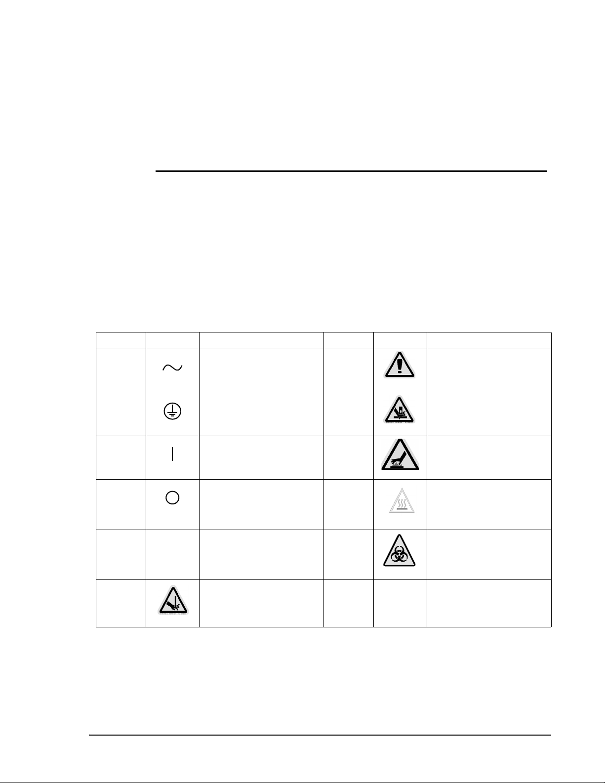
Electrical The Luminex 100 analyzer and Luminex XYP must be connected to
approved power sources. Do not perform maintenance or cleaning of
the system’s electrical components (except for fuses).
One of the following fuse replacement warning labels appears on the
back of the Luminex 100 analyzer, depending if the instrument
contains a Coherent or Uniphase laser: .
Figure 1. Fuse Replacement Warning Label - Coherent Laser
.
Figure 2. Fuse Replacement Warning - Uniphase Laser
2 - 2 PN 89-00002-00-070 Rev. A
Page 17
xMAP Technology Safety
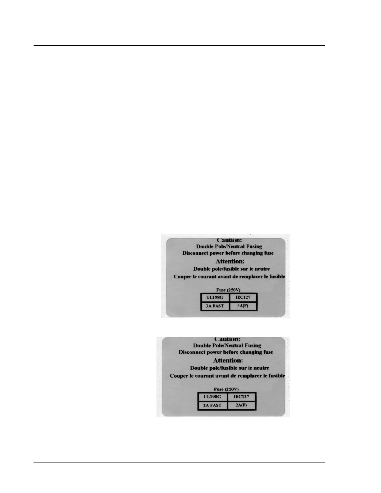
This label appears on the back of the XYP instrument.
Figure 3. Fuse Replacement Warning Label - XYP
This label appears on the back panel of the Luminex 100 analyzer
and the back panel of the XYP instrument.
Figure 4. European Safety Requirement Label
The Luminex 100 analyzer and XYP instrument comply with
European Union (EU) safety requirements and, therefore, may be
marketed in the Europe Single Market.
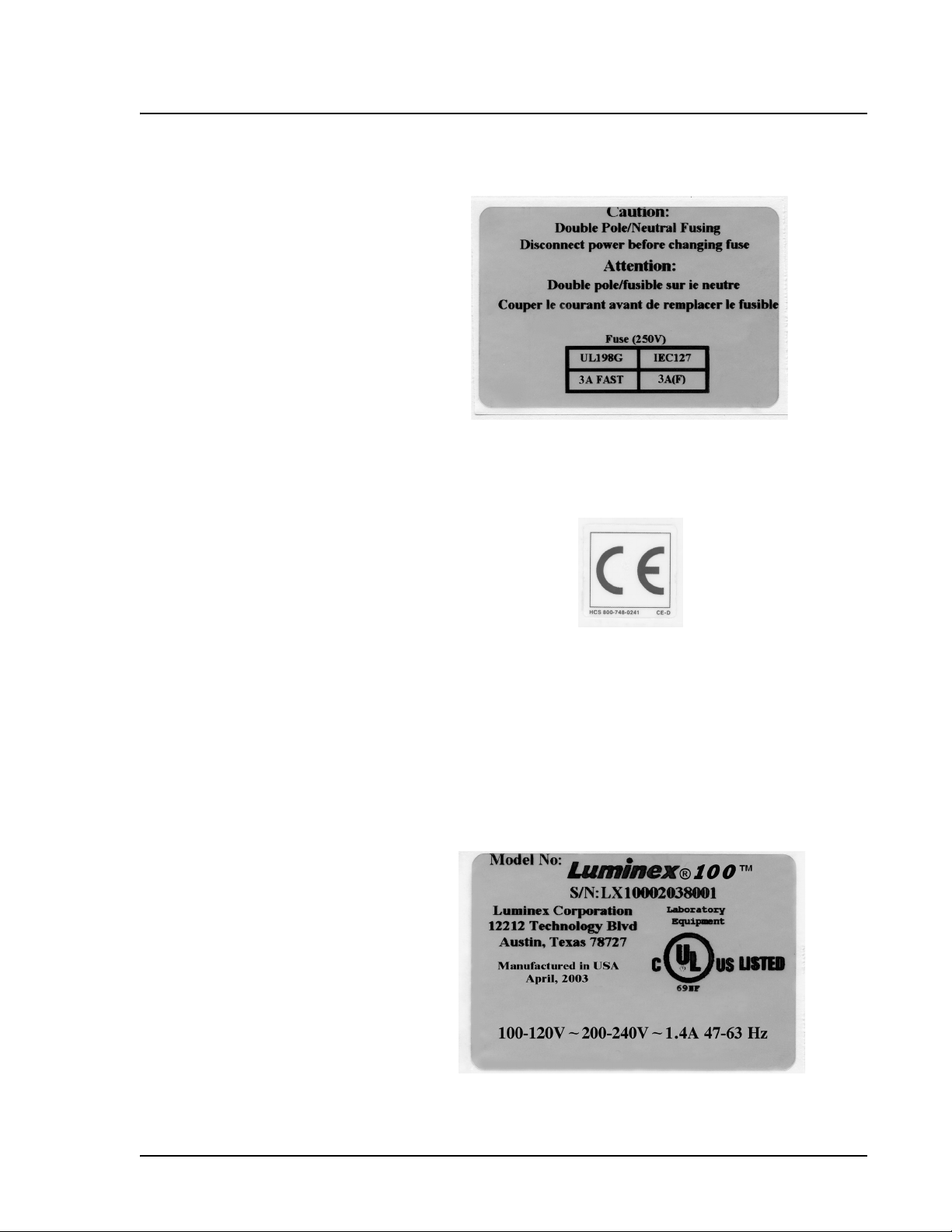
One of the following voltage labels displays on the back of the
Luminex 100 analyzer, depending if the instrument uses a Coherent
or Uniphase laser:
.
Figure 5. Luminex 100 Voltage Label (Coherent)
PN 89-00002-00-070 Rev. A 2 - 3
Page 18
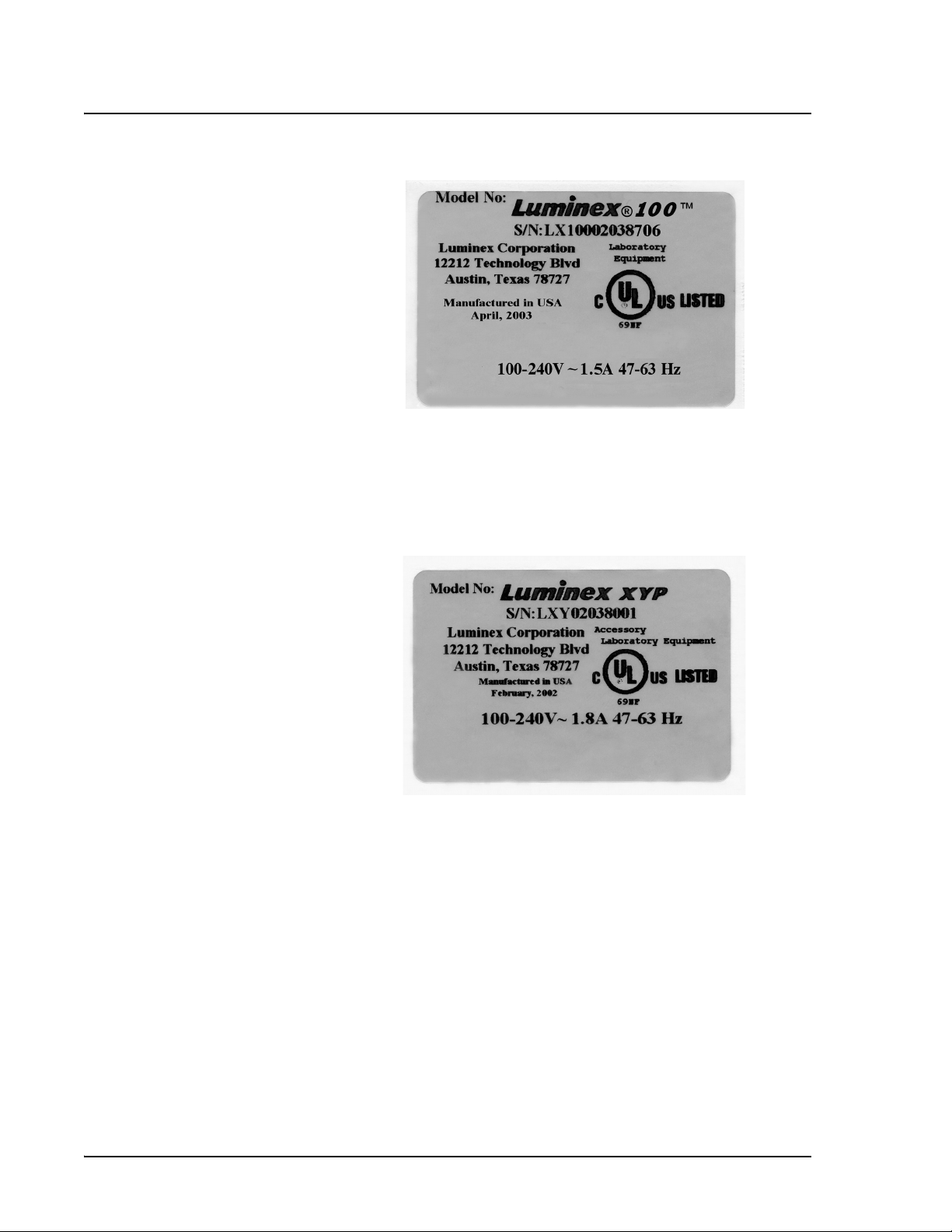
Luminex 100 IS User Manual Version 2.1 xMAP Technology
Figure 6. Luminex 100 Voltage Label (Uniphase)
The Luminex 100 analyzer has been tested by Underwriter
Laboratories, Inc® (UL).
This label appears on the back of the XYP instrument.
Figure 7. Luminex XYP Voltage Label
The XYP instrument has been tested by UL.
This system contains fluidics. In the event of a fluidic leak, turn off
all power to the system and disconnect all power cords. Remember
that the on/off switch is not a disconnect means, the power cord must
be removed from the outlet. Contact Luminex Corporation for further
information.
You must manually monitor waste levels—do not allow the waste
container to overflow! Empty the waste container each time the
sheath fluid container is filled. Do not place the waste container on
top of the instrument.
2 - 4 PN 89-00002-00-070 Rev. A
Page 19
xMAP Technology Safety
Warning: If biological samples have been tested with the
system, use your standard laboratory safety practices when
handling system waste.
Luminex 100 IS Laser
Classification
Luminex 100 Analyzer
Laser
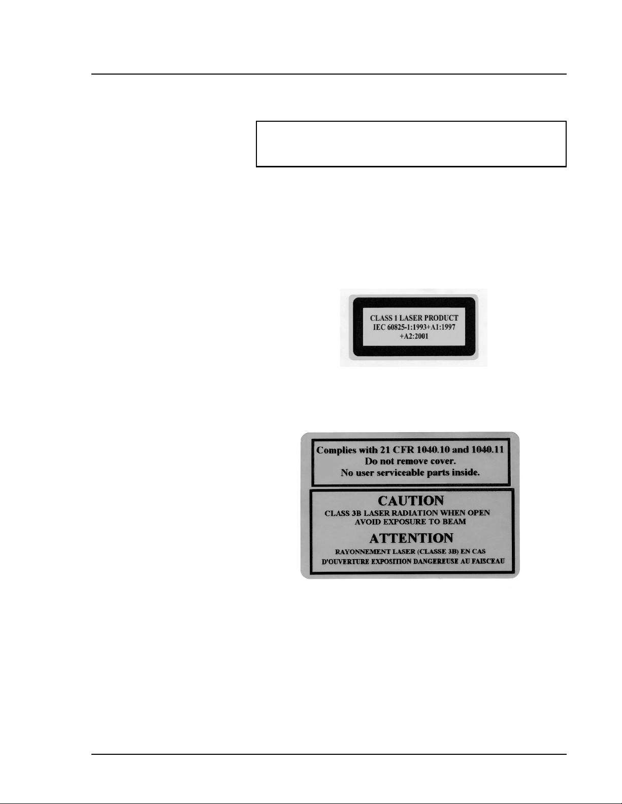
The Luminex 100 IS system classifies per FDA 21 CFR 1040.10 as a
Class II laser product consisting of a class I laser component
(Luminex 100 analyzer) and a Class II laser component (barcode
reader).
United States and international regulations require the following
warnings to appear on the instrument during operation and
maintenance.
Figure 8. Laser Class Label
This label appears on the back panel of the Luminex 100 analyzer.
Figure 9. Laser Caution Label
Under NO circumstances should the user remove the instrument
cover! When routine maintenance is performed, power to the
instrument must be OFF and the power cord must be disconnected.
PN 89-00002-00-070 Rev. A 2 - 5
Page 20
Luminex 100 IS User Manual Version 2.1 xMAP Technology
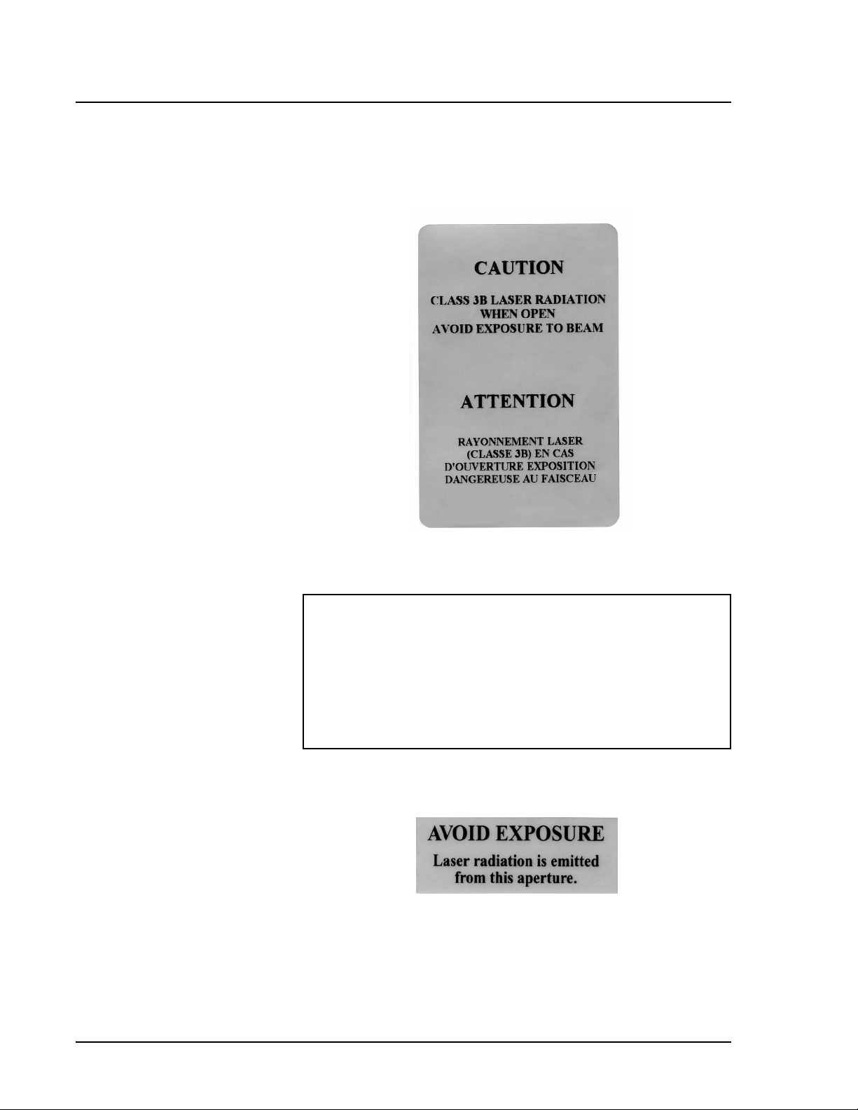
All laser apertures are located within the Luminex 100 analyzer and
are contained within a protective housing. This label appears on the
optics cover within the Luminex 100 analyzer.
Figure 10. Laser Caution Label on Optics Cover
Caution: Use of controls or adjustments or performance of
procedures other than those specified herein may result in
hazardous radiation exposure.
Attention: L’utilisation des commandes ou réglages ou
l’exécution des procédures autres que celles spécifiées dans les
présentes prescriptions peuvent être cause d’une exposition à un
rayonnement dangereux.
This label appears above the laser apertures located inside the optics
enclosure inside the Luminex 100 analyzer.
Figure 11. Avoid Exposure Label
2 - 6 PN 89-00002-00-070 Rev. A
Page 21
xMAP Technology Safety
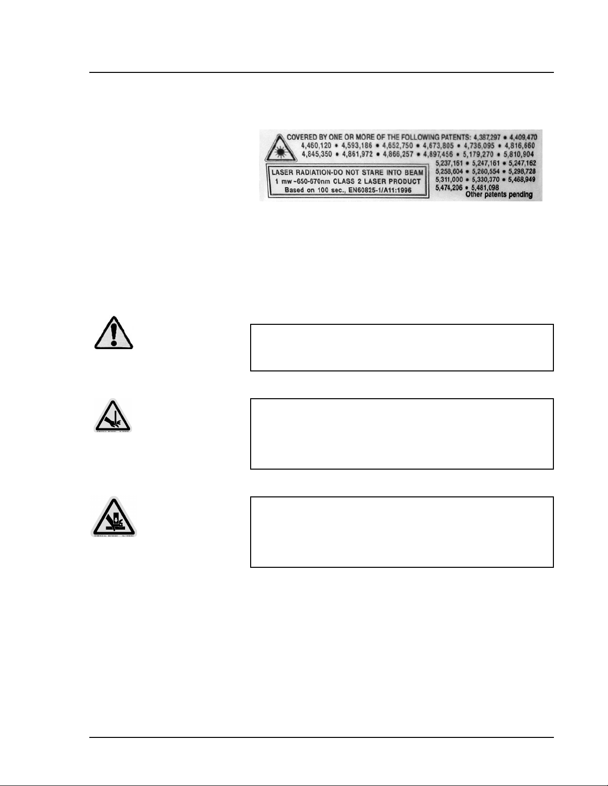
Bar Code Reader Laser This label appears on the bar code reader.
Figure 12. Bar Code Reader Laser Information Label
Do not stare directly into the beam or shine the beam into other
people’s eyes.
Mechanical
Warning: During operation, this system contains exposed,
moving parts. Risk of personal injury is present. Observe all
warnings and cautions.
Note: Access doors must be
closed while operating the
Luminex 100 analyzer. Operator
must be present during
operation.
Warning: During operation, this system contains exposed,
moving parts which could result in puncture hazard. Risk of
personal injury is present. Keep hands and fingers away from the
sample needle. If you use the optional XYP, keep hands and
fingers out of the XYP slot during operation.
Warning: During operation, this system contains exposed,
moving parts which could result in pinch point hazard. Risk of
personal injury is present. Keep hands and fingers away from the
syringe arm. If you use the optional XYP, keep hands and fingers
out of the XYP slot during operation.
PN 89-00002-00-070 Rev. A 2 - 7
Page 22
Luminex 100 IS User Manual Version 2.1 xMAP Technology
Biological
Warning: Human/animal samples may contain biohazardous
infectious agents. Where exposure (including aerosol) to
potentially biohazardous materials exists, operators should follow
appropriate biosafety procedures and use personal protective
equipment, such as gloves, gowns, laboratory coats, face shields
or masks, and eye protection and ventilation devices.
Observe all local, state, and federal biohazard handling
regulations when disposing of biohazardous waste material.
Heat
Warning: The heater plate of the optional XYP instrument may be
hot and could cause personal injury if touched. Do not touch the
heater plate.
Blue Indicator Light
The blue light above the Sample Arm simply indicates the on/off
status of the instrument, and is harmless. The blue light-emitting
diode (LED) does not emit light in the UV spectrum.
2 - 8 PN 89-00002-00-070 Rev. A
Page 23

xMAP Technology Safety
Decontamination of
the Luminex 100 IS
for Return Shipment
Sanitize and deconaminate the accessible surfaces and internal
fluidics of the Luminex 100 analyzer before you ship it back to
Luminex. This is particularly important when biohazardous samples
have been analyzed. Make a copy of this page to fill out and return
with the instrument.
Complete and return this checklist with the Luminex 100 analyzer.
1. Replace the fluid in the sheath bottle with a solution of 10%
household bleach and water.
2. Remove all specimens, disposables, and reagents from the
system.
3. Using a solution of 10% household bleach and water, sanitize the
system using the Sanitize command on the main screen of the
system. Follow this by washing twice with distilled water.
4. Disconnect the system from ac power by turning off the power
switch on the rear of the system, then unplug the Luminex 100
analyzer power cord from the wall source.
5. Disconnect the sheath fluid and waste containers.
6. Drain the sheath fluid and waste containers.
7. Rinse the waste container with 10% household bleach solution
and drain.
8. Wash all exterior surfaces with a mild detergent, followed by a
10% bleach solution.
9. Open both front doors of the instrument and clean all accessible
surfaces with mild detergent followed by a 10% bleach solution.
10. Pack the system within a biohazard bag, place it in the
corrugated box, then insert it in proper packaging materials.
Attach this checklist to the top of the corrugated box prior to
packaging in the crate.
Was there an internal leak in the system? Yes _____ No ______
Print Name:_________________________________
Signature: ___________________________________
Date: _______________________
PN 89-00002-00-070 Rev. A 2 - 9
Page 24

xMAP Technology Safety
PN 89-00002-00-070 Rev. A 2 - 10
Page 25

3
Basic Concepts
Background
Information
xMAP technology is a versatile system that measures soluble
analytes. The 100 IS performs simultaneous, discrete measurements
of multiple microsphere-based reactions from a single specimen
aliquot. For more conceptual information, refer to Practical Flow
Cytometry, 3rd edition, by Howard M. Shapiro, M.D. (New York:
Wiley-Liss Inc., 1995).
Fluidics There are two fluidic paths in the 100 analyzer. The first path
involves a syringe-driven mechanism that controls the sample
uptake. This mechanism permits small sample uptake volumes from
small reaction volumes. The syringe-driven system transports a
specified volume of sample from a sample container to the cuvette.
The sample is injected into the cuvette at a steady rate for analysis.
Following analysis, the sample path is automatically purged with
sheath buffer by the second fluidics path. This process effectively
removes residual sample within the tubing, valves, and probe.
Approximately 160 µL of sheath fluid is dispelled into each well
following sample acquisition. The second fluidics path is driven
under positive air pressure and supplies sheath fluid to the cuvette
and sample path.
Excitation The excitation system in the Luminex 100 analyzer involves two
solid-state lasers. A reporter laser excites fluorescent molecules
bound to biological reactants at the microsphere surface, and a
classification laser excites fluorochromes embedded in the
microsphere. The lasers illuminate the xMAP microspheres as they
flow single file through the cuvette. RP1 refers to the excitation
wavelength. CL1 and CL2 refer to the dyes embedded in the
microsphere. DD refers to the channel that discriminates against
doublets based on size.
PN 89-00002-00-070 Rev. A 3 - 1
Page 26

Luminex 100 IS User Manual Version 2.1 xMAP Technology
Photodiodes and a photomultiplier tube receive fluorescent signals
from xMAP microspheres. The Luminex 100 analyzer digitizes the
waveforms and delivers the signals to a digital signal processor
(DSP). Proprietary algorithms function with the DSP to greatly
increase sensitivity.
xMAP Microspheres The xMAP microspheres are highly uniform, polystyrene particles
that have been crosslinked during polymerization for physical and
Note: Protect the xMAP
microspheres from light.
thermal stability. Varying amounts of fluorochromes embedded
within each microsphere give each microsphere set an unique
fluorescent signal. To ensure the stability of this signal, it is essential
to protect the microspheres from light. Follow package
instructions for storage procedures for xMAP microspheres and
assay kits.
xMAP calibrator microspheres are used to normalize the settings for
the reporter channel, both classification channels and the doublet
discriminator channel for the Luminex 100 analyzer.
xMAP control microspheres are used to verify the calibration and
optical integrity of the system.
Software Overview This section provides a brief overview for using the Luminex 100 IS
version 2.1 software.
With the Luminex 100 IS, you work with assay kits provided by a kit
manufacturer. A template is included with each kit and is imported to
the Luminex 100 IS. The template includes a sequence of commands
required for the assay.
Once you select the template, you enter sample data into a “batch.”
Sample input can be done quickly with either the keyboard or a
barcode scanner. A batch can include as many samples as you have
for the assay and can include multiple microtiter plates. You can even
group multiple batches together into a multi-batch for efficient
processing. You can process a batch immediately or choose to
archive the batch for testing later.
As testing proceeds through the plate, you will see the display update
to show which wells have been processed. Progress is shown in both
graphic and tabular form.
3 - 2 PN 89-00002-00-070 Rev. A
Page 27

xMAP Technology Basic Concepts
System calibrators and controls are provided as part of the system.
Calibrate at least once monthly or when dCal temperature changes by
±3 degrees. You must run system controls following calibration and
as often as you like to ensure that your system continues to operate
optimally.
The software provides you with a variety of reports, including:
• Analyte reports with batch results grouped by the test in a batch.
• Patient summary reports with batch results grouped by each
patient or unknown in a batch.
• Levy-Jennings reports with information about calibrators and
system controls as well as assay standards and controls.
• Maintenance reports with a history of all maintenance operations
performed during a specified period of time.
• Calibration trend reports with results of calibration commands
performed over a specified time period.
• Verification trend reports with results of system controls
performed over a specified time period.
These reports let you look at specific details regarding the samples
you process through the Luminex 100 IS as well as system operation.
System tools help you monitor the system including a display
showing real-time system property values and a message log. Errors
are shown in the message log and also on your reports. You can even
add comments to specific results in some of these reports as needed.
To keep track of your reagents, the Luminex 100 IS stores lot
numbers, expected values, and expiration information.
A comprehensive set of self-diagnostic tests ensure that your system
is working correctly. These tests are performed at startup and can be
requested at any time. If any problem is detected, an error message
appears in the message log to inform you.
PN 89-00002-00-070 Rev. A 3 - 3
Page 28

Luminex 100 IS User Manual Version 2.1 xMAP Technology
3 - 4 PN 89-00002-00-070 Rev. A
Page 29
4
Installation
Assemble and
Power the Luminex
100 IS System
Hardware Setup The following sections describe how to set up the hardware
Connect the
Luminex 100
Analyzer and XYP
Instrument
Before installing the system, ensure that the facility complies with all
system and safety requirements. Read the safety information that
begins in
instrument to minimize temperature fluctuations.
components of the Luminex 100 IS.
To assemble and power on the system:
1. Unpack the Luminex 100 analyzer, the XYP instrument, and the
2. Place the XYP instrument on a clean, flat surface.
“Safety Precautions” on page 2-2. Try to position the
PC and monitor. Review “Hardware” on page 5-2 and identify
each system component.
Note: Due to the weight of the
Luminex 100 analyzer, two people
are required for lifting.
PN 89-00002-00-070 Rev. A 4 - 1
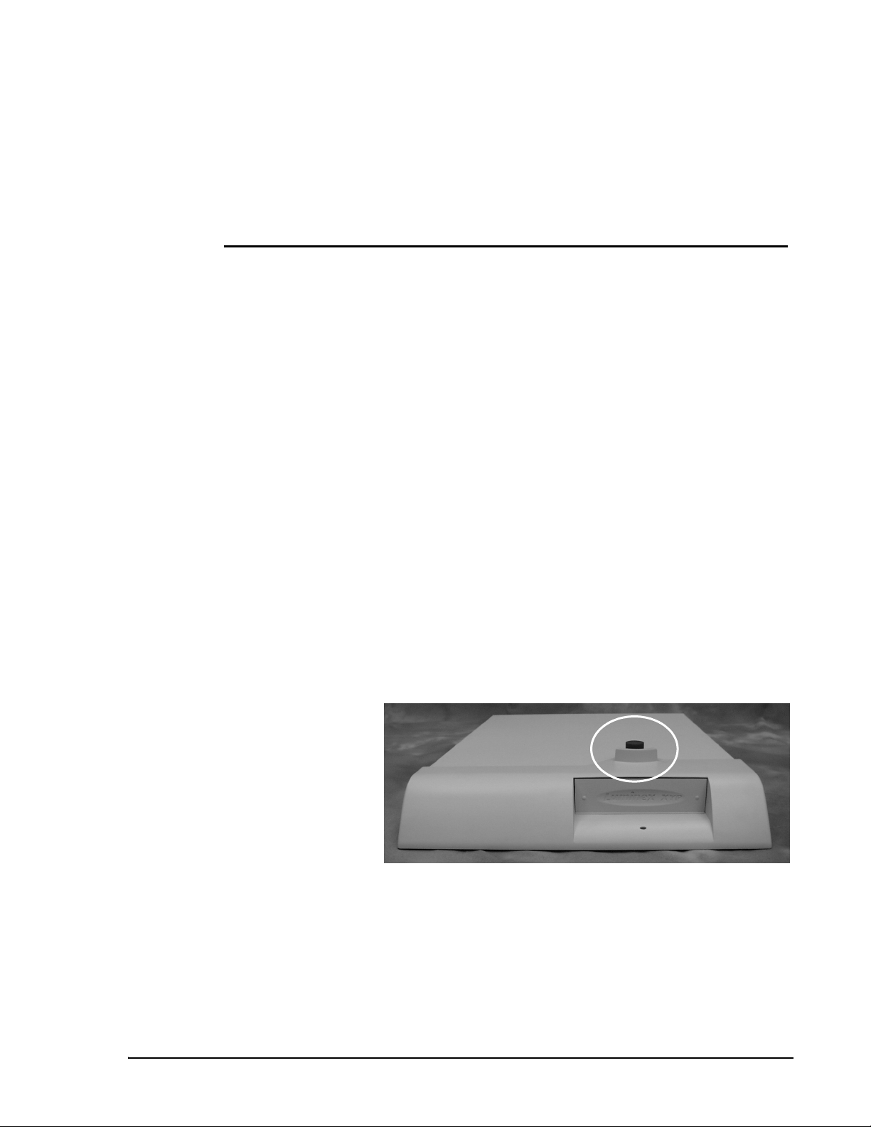
3. Remove the red shipping pin. Leave the silver knob in the XYP
instrument.
4. Attach the power cord to the power input module of the XYP
instrument and attach the communication cable to the XYP
Figure 13. XY Platform with Red Shipping Pin
Page 30
Luminex 100 IS User Manual Version 2.1 xMAP Technology
instrument. Do not plug the XYP instrument into the power
outlet.
5. Place the Luminex 100 analyzer onto the XYP instrument.
6. Attach the power cords to the input module of the Luminex 100
analyzer and attach the USB cable to port 1 on the Luminex 100
analyzer. Do not plug into the power outlet. Make sure that the
power switches to the Luminex 100 analyzer and to the XYP
instrument are off. See connections photos on page 4-3 or the
diagram on page 4-4.
7. Install the alignment guide (translucent plastic tube) by screwing
it into the XYP instrument where shown. Adjust the position of
the Luminex 100 analyzer with the XYP instrument until the
alignment guide threads screw in completely.
Note: The ac power
requirements may vary from
location to location and region to
region.
Alignment
guide
Figure 14. Alignment Guide
8. Set the voltage selection switch on the PC’s power supply to
match the ac power available at your location to prevent damage
to your PC.
Set it to 115 volts (V) in most of North and South America and
some Far Eastern countries such as Japan, South Korea, and
Taiwan.
Set it to 230 volts (V) in most of Europe, the Middle East, and
the Far East.
4 - 2 PN 89-00002-00-070 Rev. A
Page 31

xMAP Technology Installation
Refer to the documentation that came with your PC to determine
if changing the voltage selection switch is required, and for
Note: Do not place the PC or
monitor on top of the Luminex
100 analyzer.
instructions on changing the switch setting.
9. Place the PC to the right of the Luminex 100 and XYP
instruments.
10. Place the monitor on top of the PC and connect the monitor cable
to the PC.
1
2
3
4
5
1. Monitor 4. Computer
2. Barcode Reader 5. XYP
3. Analyzer
Figure 15. Luminex 100 IS Setup
11. Connect the Luminex 100 analyzer and the XYP instrument
communications cables to the PC. See the following iillustration.
PN 89-00002-00-070 Rev. A 4 - 3
Page 32

Luminex 100 IS User Manual Version 2.1 xMAP Technology
1
7
6
5
4
3
1. USB Communication Cable 9. Instrument USB Cables
2. Luminex XYP Instrument 10. Network Connection
3. Luminex XYP Instrument to PC Serial
Cable
4. Power Cords 12. Y-Cable (to keyboard port)
5. Luminex XYP Instrument Power Switch 13. Mouse Cable (top port)
6. Luminex 100 Analyzer Power Switch 14. Com 2 Port
7. Luminex 100 analyzer 15. Luminex XYP Instrument Serial
8. PC 16. Com 1 Port
8
9
2
16
14
15
11. Monitor Cable
Cable
13
10
11
12
Figure 16. Luminex 100 IS Connections
12. Connect the barcode reader, mouse, and keyboard as shown in
Figure 17.
4 - 4 PN 89-00002-00-070 Rev. A
Page 33

xMAP Technology Installation
4
1
Note: The sheath and waste
containers must be placed on
the same surface as the XYP
instrument. Do not place the
containers on top of the Luminex
100 analyzer.
3
2
1. Keyboard 3. Y-Cable
2. Barcode Reader 4. Mouse
Figure 17. Connecting the PC, Mouse, Barcode Reader, and
Keyboard
13. Fill the sheath bottle with sheath fluid to just below the air intake
fitting. Install the sheath and waste containers to the left side of
the Luminex 100 analyzer, connecting them with tubing to the
color-coordinated connectors on the side of the Luminex 100
analyzer.
If your system uses the Luminex Sheath Delivery system, see
“Appendix A: Luminex Sheath Delivery System” on page A-1.
14. Plug the Luminex 100 analyzer, XYP instrument, PC, and
monitor power cords into approved outlets. We strongly
recommend using an uninterruptible power supply to protect the
system from power variations. Refer to “Recommended
Additional Equipment” on page 5-7 for more information.
PN 89-00002-00-070 Rev. A 4 - 5
Page 34

Luminex 100 IS User Manual Version 2.1 xMAP Technology
Install or Replace the XYP
Instrument Sample Probe
To install the XYP instrument Sample Probe, which is longer
than the probe shipped with the system, follow these steps:
1. Make sure the Luminex 100 analyzer power switch is off and
that the XYP instrument and the Luminex 100 analyzer power
cords are unplugged from the outlet.
2. Remove the light housing directly above the Sample Arm by
grasping and firmly pulling out. The housing remains attached
by a wire. Place the housing on top of the analyzer.
Figure 18. Light Housing
4 - 6 PN 89-00002-00-070 Rev. A
Page 35

xMAP Technology Installation
3. Remove the Cheminert fitting by turning the connector
counterclockwise. If the tubing is difficult to remove, push up
gently on the sampling probe.
1
2
1. Cheminert Fitting 2. Sample Probe
Figure 19. Cheminert Fitting
4. Remove the sampling probe by grasping the probe and gently
pushing up.
Caution: The XYP instrument sampling probe should slide up
easily while removing it from the Sample Arm. If you feel
resistance, do not force the probe up. Contact Customer Support.
5. Insert the XYP instrument sampling probe and replace the tubing
connector. Tighten the connector by turning the connector
clockwise, being careful that the threads are correctly aligned.
Hand tighten only.
PN 89-00002-00-070 Rev. A 4 - 7
Page 36

Luminex 100 IS User Manual Version 2.1 xMAP Technology
Figure 20. The XYP Instrument Sampling Probe
6. Re-install the light housing by pushing until it snaps into place.
7. Install the shield to cover the sampling probe area. This shield
should only be removed for making adjustments to the probe.
Figure 21. The Clear Plastic Shield
4 - 8 PN 89-00002-00-070 Rev. A
Page 37

xMAP Technology Installation
8. Plug in the XYP instrument and the Luminex 100 analyzer.
Install the XYP
Instrument
Reservoir
The XYP instrument reservoir is used for maintenance functions in
the Luminex 100 analyzer.
To install the XYP instrument reservoir:
1. Turn on the XYP instrument, the Luminex 100 analyzer, and the
PC. Wait for the Luminex 100 IS software to start.
2. Enter the lot numbers and target information (found in
Certificate of Quality) for the calibrators and system controls, if
necessary. Click the Apply and Save button. If there is
information in the database, the system does not require you to
enter the information. Click Done.
3. Click the Eject/Retract button to eject the plate holder.
4. Insert the reservoir in the upper right corner of the plate holder.
Figure 22. The XYP Instrument Reservoir
5. Click the Eject/Retract button to retract the plate holder.
Install the XYP
Instrument Heater
Use the XYP instrument heater block as required by your assay kit
instructions. When not in use, you can store the XYP instrument
Block (Optional)
PN 89-00002-00-070 Rev. A 4 - 9
Page 38

Luminex 100 IS User Manual Version 2.1 xMAP Technology
heater block in the bracket inside the left access door of the Luminex
100 analyzer.
To install the XYP instrument heater block:
1. Click the Eject/Retract button to eject the plate holder.
2. Insert the XYP instrument heater block on the plate holder.
Adjust the Sample
Probe Vertical
Height
Figure 23. The XYP Instrument Heater Block
3. Click the Eject/Retract button to retract the plate holder.
You need to adjust the vertical height of the Sample Probe each time
the type or style of microtiter plate is changed.
1
2
1. Thumb Wheel 2. Height Adjustment Locking Screw
Figure 24. Thumb Wheel and Height Adjustment Locking Screw
4 - 10 PN 89-00002-00-070 Rev. A
Page 39

xMAP Technology Installation
To adjust the vertical height of the Sample Probe:
1. Turn on the XYP instrument, the Luminex 100 analyzer, and PC.
Wait for the Luminex 100 IS software to start.
2. Remove the clear plastic shield that covers the sampling probe
area.
3. In a 96-well microtiter plate where overall height is no more than
0.75 inches, place appropriate alignment tool in the plate.
For a standard plate with flat-bottomed wells, stack two of the
larger (5.08 mm diameter) alignment discs together and place
into well A1.
For a half-volume plate with flat-bottomed wells, stack two of
the smaller (3.35 mm diameter) alignment discs together and
place into well A1.
For a plate with conical wells, place one alignment sphere into
well A1.
4. Click Eject/Retract to eject the plate. Place the 96-well
microtiter plate on the plate with position A1 in the top left
corner and click Eject/Retract to retract the plate.
5. Use the 3/32 inch hexagonal allen wrench to loosen the height
adjustment locking screw. See Figure 24.
6. Click the Maintenance tab.
7. Click the Sample Probe Down button to lower the Sample
Probe.
8. Using the thumb wheel, lower the probe until it is just touching
the top of the alignment discs or sphere.
9. Use a 3/32 inch hexagonal allen wrench to tighten the height
adjustment locking screw.
10. Click Sample Probe Up to raise the sampling probe.
11. Replace the clear plastic shield that covers the sampling probe
area.
PN 89-00002-00-070 Rev. A 4 - 11
Page 40

Luminex 100 IS User Manual Version 2.1 xMAP Technology
Initialization
Initialize the PC Upon powering your system, the PC runs through several self-
diagnostic tests to verify that the computer system is set up to run the
system software application.
To initialize the PC:
1. Turn on the power button on the back of the Luminex 100
analyzer and turn on the PC. If you have these devices plugged
into a UPS or surge suppressor protector rather than directly into
the wall outlet, turn on the surge protection power strip power
switch.
2. The PC and system begin initializing automatically.
If the system initializes successfully, the software application
launches. If the system does not run through its initial tests
successfully, the software application does not launch and a warning
appears on your PC’s monitor screen.
Initialize the
Luminex 100 IS
Software
The PC runs through the following tests during initialization:
•RAM
•ROM
• Communications with hard drive
• Communications with mouse
• Communications with keyboard
After the PC has been initialized, the Luminex 100 IS software runs
through self-diagnostic tests. If a problem is detected, a warning
appears on the screen. See “Unknown Diagnostic Error” on page 9-5
for more information.
4 - 12 PN 89-00002-00-070 Rev. A
Page 41

xMAP Technology Installation
Installation Drawing
)
.
g
k
6
4
.
4
0
2
0
(
1
.
x
b
l
e
n
2
i
9
.
m
3
u
5
L
)
.
g
k
9
8
D
.
8
S
(
.
x
b
l
e
n
i
5
5
m
.
u
9
L
1
f
l
e
h
s
e
h
:
t
-
s
f
t
f
n
o
e
,
n
C
o
P
p
f
l
m
e
o
h
c
s
r
-
o
e
j
h
a
t
-
m
f
f
5
o
f
,
o
D
s
S
t
s
x
i
e
s
n
n
i
o
m
c
u
L
m
,
e
t
P
s
Y
y
X
S
x
S
I
e
n
0
i
0
m
1
u
x
L
e
,
n
0
i
0
m
1
u
x
L
:
e
s
e
n
i
e
h
t
m
T
o
u
.
L
N
1
r
o
f
e
c
n
d
a
e
r
t
t
a
i
e
l
m
c
o
e
l
n
b
e
a
e
c
b
d
e
n
v
a
a
,
h
t
r
s
e
u
d
a
a
h
e
x
r
e
/
e
e
d
k
o
a
t
c
r
n
i
a
b
d
n
d
.
a
n
y
.
t
i
a
g
r
s
n
s
a
i
C
l
l
e
c
P
o
e
h
T
.
r
e
d
a
e
r
e
d
o
c
r
a
b
c
r
o
c
c
o
a
f
r
h
g
o
f
c
n
t
i
i
e
w
w
c
a
s
n
r
r
a
d
r
e
a
s
i
w
e
l
h
o
t
p
C
m
o
2
r
f
y
l
n
o
g
n
i
h
t
r
a
e
e
.
v
i
)
)
t
.
.
c
g
g
e
k
k
t
o
7
1
r
.
6
.
p
1
6
2
h
(
7
t
i
(
.
.
w
b
l
b
l
s
t
5
.
7
e
)
4
l
.
.
6
t
.
g
6
u
8
k
4
o
6
8
n
1
o
t
7
:
w
.
t
n
i
o
7
h
h
9
d
g
(
i
s
e
.
e
t
g
b
o
w
l
g
n
u
2
l
,
m
r
e
o
t
s
o
l
y
f
s
n
p
o
o
t
x
r
o
e
t
b
n
d
i
u
u
o
l
f
c
l
h
a
t
t
a
o
e
T
h
.
s
(
3
.
1
p
)
.
l
5
e
a
1
b
u
2
n
d
l
t
a
u
h
m
o
g
i
r
h
e
s
e
w
s
s
u
d
m
r
e
e
o
t
c
c
y
n
s
e
e
r
l
n
i
e
a
f
t
L
e
o
.
r
T
(
4
I
°
°
5
0
.
.
-
+
°
0
°
°
5
0
.
.
-
+
°
0
n
o
i
t
a
.
l
l
)
t
a
f
i
t
l
s
o
n
i
t
d
e
l
n
p
a
o
e
g
p
n
i
g
2
a
s
k
e
c
r
i
a
u
p
q
n
.
e
r
s
o
s
0
s
e
0
n
c
1
o
c
i
t
X
a
c
L
(
e
u
r
l
c
t
a
n
s
u
a
n
i
n
n
a
e
g
t
n
m
i
n
l
i
r
d
a
e
n
m
s
a
u
h
e
s
d
d
u
e
f
i
n
l
,
a
p
h
p
g
c
t
u
n
i
i
s
p
w
f
p
s
o
i
r
h
s
e
s
n
w
o
w
i
o
t
o
l
c
P
l
u
o
r
t
F
s
.
6
n
i
5
e
l
b
a
b
o
r
p
e
c
n
a
r
a
e
l
.
c
e
t
c
s
n
n
u
o
i
a
a
r
s
h
a
n
x
e
e
e
l
t
l
c
x
o
e
e
s
l
y
o
b
r
a
a
r
e
C
a
T
7
8
g
n
i
t
r
o
p
p
u
S
e
t
.
s
s
a
u
w
n
i
m
m
r
o
r
e
f
t
t
e
s
n
u
i
l
a
h
e
t
x
s
e
a
l
w
o
s
r
o
o
r
r
e
e
a
t
l
i
f
e
l
p
b
a
a
c
b
o
e
r
l
t
t
P
o
.
b
9
)
e
.
c
g
a
k
f
r
8
u
4
S
P
.
0
Y
1
X
(
.
x
b
e
l
n
i
5
0
m
.
u
2
L
3
w
e
i
V
c
i
r
t
e
m
o
s
I
)
t
s
n
c
i
i
t
o
s
P
o
t
n
s
g
e
u
a
b
i
a
o
h
D
r
x
P
E
d
t
n
r
l
a
o
o
h
s
n
S
o
o
r
i
t
g
e
a
n
l
A
i
l
s
a
e
t
l
U
s
b
n
a
I
n
b
e
r
o
o
h
r
F
P
(
W
e
c
a
f
r
u
S
g
n
i
t
r
o
p
p
u
S
0
5
.
7
t
l
e
l
s
g
o
b
u
n
i
s
i
r
l
a
s
i
o
o
r
h
s
A
x
o
e
o
E
A
C
P
)
2
m
m
0
~
4
.
0
2
0
.
5
6
1
(
)
m
m
0
.
8
.
2
0
5
(
x
e
n
i
m
u
L
)
m
m
0
8
.
.
2
0
5
(
)
m
m
0
5
.
0
9
1
(
t
s
u
a
h
x
E
8
e
y
c
a
n
r
a
T
r
a
P
e
l
Y
C
X
e
c
n
a
r
a
e
l
C
w
e
i
V
e
d
i
S
t
h
g
i
R
e
k
a
t
n
I
r
i
A
g
n
i
l
o
o
C
7
6
)
)
m
m
m
m
6
.
2
0
0
.
.
.
1
6
4
3
0
7
1
(
(
t
g
n
i
r
l
i
o
A
o
C
g
n
i
l
o
o
6
C
t
e
l
l
s
s
o
b
u
u
i
s
a
a
s
o
h
s
h
r
x
x
o
e
E
E
P
A
w
e
i
V
e
r
k
k
i
a
c
A
t
n
a
I
B
PN 89-00002-00-070 Rev. A 4 - 13
Page 42

xMAP Technology Installation
PN 89-00002-00-070 Rev. A 4 - 14
Page 43

The System
5
Theory of Operation Luminex 100 IS technology is based on flow cell fluorometry with
Luminex-developed innovations. The fluidics, optics, robotics,
temperature control, software, and microspheres work together to
enable simultaneous analysis of up to 100 analytes in a single test
sample. Assay analysis requiring temperature control is provided
through the XYP instrument heater block.
There are two fluidics paths in the Luminex 100 analyzer. The first
path involves a syringe-driven mechanism that controls the sample
uptake. This mechanism permits small sample uptake volumes from
small reaction volumes. The syringe-driven system transports a
specified volume of sample from a sample container to the cuvette.
The sample is injected into the cuvette at a steady rate for analysis.
Following analysis, the sample path is automatically purged with
sheath buffer by the second fluidics path. This process removes
residual sample within the tubing, valves, and probe. The second
fluidics path is driven by positive air pressure and supplies sheath
fluid to the cuvette and sample path.
Sheath fluid is the delivery medium of the sample to the optics
component. The analysis sample is acquired using a Sample Probe
from a 96-well microtiter plate via the XYP instrument and injected
into the base of the cuvette. The sample then passes through with
sheath fluid at a reduced rate resulting in a narrow sample core to
ensure that each microsphere is illuminated individually. The sample
injection rate is such that the microspheres are introduced to the
optics path as a series of single events.
The optics assembly consists of two lasers. One laser excites the dye
mixture inside the xMAP microspheres and the second laser excites
the dye bound to the surface of the xMAP microspheres. Avalanche
PN 89-00002-00-070 Rev. A 5 - 1
Page 44

Luminex 100 IS User Manual Version 2.1 xMAP Technology
photo diode (APD) detectors measure the excitation emission
intensities of the color coding classification dye mixtures inside the
microspheres and a photomultiplier tube detects the excitation
emission intensity of the reporter dye bound to the surface of the
microspheres. High speed digital signal processors and advanced
computer algorithms provide analysis of the xMAP microspheres as
they are processed through the Luminex 100 analyzer. Results of the
analyses are processed and provided in a report format.
Hardware The Luminex 100 IS allows you to test clinical samples. The system
includes the following hardware:
• Luminex 100 analyzer
• PC, monitor, and accessories
• XYP instrument
• Power cables
• Alignment guide
• Short ampling probe
• XYP instrument sampling probe
• Sample tube holder, 1.2 mL
• Sample tube holder, 1.5 mL
• Reservoir
•Shield
•Heater block
• Alignment tools
• Sheath fluid container
• Waste container
• Communications: 1 serial communication cable
• Communications: 1 USB communication cable
• Bar code reader
• Hexagonal allen wrench
xMAP Reagents • Classification calibration microspheres (CAL1)
• Reporter calibration microspheres (CAL2)
• Classification control microspheres (CON1)
• Reporter control microspheres (CON2)
• Sheath fluid
5 - 2 PN 89-00002-00-070 Rev. A
Page 45

xMAP Technology The System
Required
Laboratory
• Household bleach
• 70% isopropanol
• Mild detergent
Reagents
Software Luminex 100 IS software provides complete control of the system
and performs data analysis. Your Luminex 100 IS is preloaded with
the Luminex 100 IS software. However, we supply a software CD in
case you need to reinstall the software.
This software requires a dedicated system. Unauthorized additional
software is prohibited and may result in improper operation of the
system.
Luminex 100 IS
Performance
Specifications
Speed • Speed: greater than or equal to 933 MHz Intel® Pentium® III
processor with 256 MB RAM
• USB communications link for fast data transfer
• Automatic transfer of assay templates and new reagent
information into the system via a 3½” floppy disk or large
capacity read/write CD
• Installation < 4 hours
• System calibration < 10 minutes
• System controls < 10 minutes
• Barcode reader entry of sample IDs
• Automatic post-analysis
• Analyze one 96-well plate/hour depending on manufacturer’s kit
• Up to 100 xMAP microsphere sets per sample
• Sheath flowrate 90 µL/sec ± 5 µL
• Sample injection rate into detector area 1 µL/sec ± 0.05 µL
• System warmup 30 minutes: Systems that remain inactive for at
least four hours will require a warm-up to restart the lasers. After
acquiring sample, running system calibrators, running system
controls, and warming up the instrument, the system resets the
four-hour internal clock.
PN 89-00002-00-070 Rev. A 5 - 3
Page 46

Luminex 100 IS User Manual Version 2.1 xMAP Technology
Accuracy and Precision • Sample uptake volume ± 5%
• Classification of microspheres > 80%
• Misclassification of microspheres < 0.5%
• Temperature control 0°C to +3°C of target
• Internal sample carry over < 0.9%
• Soluble background fluorescence emission at 575 nm
automatically subtracted from fluorescence intensity values
Sensitivity • Detect 1000 fluorochromes phycoerythrin (PE) per microsphere
• Reporter channel dynamic range: 3.5 decades
Capacity The specifications below reflect minimum capacity values:
• 10 GB hard drive
• Store data for up to 240,000 test results
• 1.4 MB 3½” floppy disk
• 100 MB read/write CD ROM
• Analyze multiple 96-well plates per batch
• Analyze multiple assay templates per plate
• Distinguish a minimum of 1 to a maximum of 100 unique xMAP
microsphere sets in a single sample
• Detect and distinguish surface reporter fluorescence emissions at
575 nm on the surface of 1-100 unique xMAP microspheres sets
in a single sample
• Reporter channel range: 3.5 decades of detection
• Sample core: 15 - 20 µm core at 1 µL/sec sample inject rate
• Maintain samples at a constant temperature from 35°C to 55°C
(95°F to 131°F)
• Automatic sampling from a 96-well plate
• Start sampling from any well position
• Sheath container and waste container hold enough volume to run
up to two 96-well plates between refills
• Microtiter plates with 96 wells must be compatible with the XYP
instrument plate holder. The following microtiter plate types are
compatible with the XYP instrument plate holder: flat bottom,
conical, round, filter bottom, half plates [overall height no more
than 0.75” (19 mm)], any color
• Microtiter plates with 96 wells must be compatible with XYP
instrument heater block temperature from 35°C to 55°C (95°F to
131°F) when performing heated assays and using the heater
block.
5 - 4 PN 89-00002-00-070 Rev. A
Page 47

xMAP Technology The System
Luminex 100
Analyzer
General • Operating temperature: 15°C to 30°C (59°F to 86°F)
• Storage temperature: 0°C to 50°C (32°F to 122°F)
• Humidity: 20% to 80%, noncondensing
• Altitude: Operation up to 2400 m (7874 ft.) above mean sea level
• Physical dimensions: 43 cm (17 inches) W x 50.5 cm (20 inches)
D x 24.5 cm (9.5 inches) H
• Weight: maximum of 25 kg (60 lbs.)
• UL installation category: UL Installation Category II, as defined
in Annex J of UL 61010A-1
• Pollution degree: UL Pollution Degree 2, as defined in Section
3.7.3.2 of UL 61010A-1
• Shipping and storage: The allowable shipping and storage
temperature and humidity ranges are 0°C to +50°C and 20-80%
noncondensing, respectively
• Input voltage range: 100 - 240 Vac, 1.5 Amp, 47-63 Hz or 100 120 Vac, 1.4 Amp, 47-63 Hz. (refer to the serial number label on
the rear panel of the instrument)
• AC inlet fuse: 3 Amp, 250 Vac, fast acting or 2 Amp, 250 Vac,
fast acting (refer to the fuse label on the rear panel of the
instrument)
Optics • Reporter laser: 532 nm, nominal output 10-16.5 mW, maximum
500 mW, frequency-doubled diode; mode of operation,
continuous wave (CW)
• Classification laser: 635 nm, 8 mW, maximum output 25
mW, diode; mode of operation, continuous wave (CW)
• Reporter detector: Photomultiplier tube, detection bandwidth of
565 - 585 nm
• Classification detector: Avalanche photo diodes with temperature
compensation
• Doublet discrimination detector: Avalanche photo diodes with
temperature compensation
Fluidics • Sheath flow rate: 90 µL ±5 µL/seconds
• Cuvette: 200 micron square flow channel
• Sample injection rate: 1 µL/second
• Sample uptake volume: 20 - 200 µL
PN 89-00002-00-070 Rev. A 5 - 5
Page 48

Luminex 100 IS User Manual Version 2.1 xMAP Technology
Electronics • Reporter channel detection: A/D resolution 14 bits
• Communications interface: USB
• XYP instrument, communications interface: RS 232
XYP Instrument
General • Ambient temperature: 15°C to 30°C (59°F to 86°F)
• Humidity: 20% to 80%, noncondensing
• Altitude: operation up to 2400 m (7874 ft) above mean sea level
• Physical dimensions: 44 cm (17.25 inches) W x 60 cm (23.5
inches) D x 8 cm (3 inches) H
• Weight: 15 kg (33 lbs.)
• UL installation category: UL Installation Category II, as defined
in Annex J of UL 61010A-1
• Pollution degree: UL Pollution Degree 2, as defined in Section
3.7.3.2 of UL 61010A-1
• Heater operating range: 35°C to 55°C (95°F to 131°F) with
tolerance 0°C to +2°C
• XY Platform, input voltage range: 100 - 240 V~, 1.8 Amps,
47 - 63 Hz
• AC inlet fuse: 3 Amp, 250 Vac, fast acting
PC Specifications • Computer: a Pentium® III or equivalent class PC, minimum
speed 933 MHz
• Main memory: minimum of 256 MB
• Hard disk drive: 10 GB minimum storage capacity
• Communications, serial ports: Minimum of 2 RS-232 compatible
serial ports
• Communications, parallel pointing device and serial ports:
Minimum of 1 parallel, 1 PS/2 compatible pointing device, and 2
RS-232 compatible serial ports
• Communications, USB port: Minimum of one USB Version 1.1
compatible high speed port
• Read, write removable media: CDR/W-type drive, standard 1.44
MB 3.5-inch disk drive
• Operating system support: MS Windows
• CE marked and UL listed
• Two-button mouse or equivalent
• Monitor: A minimum of 17-inch diagonal monitor
• Keyboard: a 104-key keyboard or equivalent
®
5 - 6 PN 89-00002-00-070 Rev. A
Page 49

xMAP Technology The System
• Power cords: Power cords specific to the country of use are
included in the system as required
• Power: 115-230 V~, 5.6 Amps, 50-60 Hz
Recommended Additional
Equipment
Uninterruptible Power
Supply (UPS)
Luminex highly recommends using an uninterruptible power supply
(UPS) to protect your system from a power outage. Choose a supply
that can provide 1050 Watts for at least 45 minutes. The UPS should
be UL listed, CSA certified, CE marked when used internationally.
Surge Protector If you do not use a UPS, as a minimum, use a surge protector.
Choose a protector that meets your needs. Factors to consider include
electrical environment, endurance, suppressed voltage rating, and
method of protection. It should have six outlets, rated at least 1500
Watts, and be UL listed, CSA certified, CE marked for nondomestic
use when used internationally
Printer • Printer, HP LaserJet 2100xi
Bar Code Labels Use the Code 128 barcode label type when scanning bar code labels
into the system as patient identities.
Vortex • VWR product number 58816-121: Speed range 0 - 3200 rpm or
equivalent
Bath Sonicator • Parmer product number 08849-00: Operating frequency 55 kHz
or equivalent
System Overview The system consists of three subsystems: electronic, fluidic, and
optical. The following section describes the user-accessible
components of each subsystem.
PN 89-00002-00-070 Rev. A 5 - 7
Page 50

Luminex 100 IS User Manual Version 2.1 xMAP Technology
Figure 25. Luminex 100 IS Setup
Electronics
Power Input
Module
P1
Communications
Port (SB9-PIN)
Luminex 100
Analyzer
Ventilation Filter
XYP Instrument
Ventilation Filter
The power input module operates from 100 to 120 Vac, 200 to 240
Vac and 47 to 63 Hz. The power input module contains the Luminex
100 analyzer on/off switch and fuses.
Used to connect the Luminex 100 analyzer or the XYP instrument to
the computer.
Located on the bottom of the Luminex 100 analyzer, the filter must
be checked and cleaned as necessary. For proper ventilation, do not
obstruct the area below and allow at least 2 inches (5 cm) of
clearance around the instrument.
Located at the back of the XYP instrument, the filter cleans the air
that cools the internal components of the XYP instrument.
5 - 8 PN 89-00002-00-070 Rev. A
Page 51

xMAP Technology The System
1
2
3
Fluidics
4
5
6
1. Air intake filter access door
2. Power input module
3. Power switch
4. XYP instrument ventilation filter
5. Communications ports (DB9)
6. Analyzer ventilation filter (on bottom)
Figure 26. Back of the Luminex 100 Analyzer and XYP Instrument
Sample Arm The Sample Arm transports the sample from the sample tube to the
cuvette. Upon operation, the carriage drops automatically to the
microtiter well for sample retrieval.
PN 89-00002-00-070 Rev. A 5 - 9
Page 52

Luminex 100 IS User Manual Version 2.1 xMAP Technology
XYP Instrument
Sample Probe
A stainless steel Sample Probe acquires a sample. A shorter probe is
provided for shipping and troubleshooting.
Warning: During operation, this system contains exposed moving
parts that result in puncture hazard. Risk of personal injury is
present. Keep hands and fingers away from the Sample Probe.
The shield should be in place.
Cheminert® Fitting This fitting may be disconnected to allow replacement of the Sample
Probe as necessary.
This guides the Sample Probe into the XYP instrument.
Cheminert fitting
Sample arm
XYP sampling probe (see
Shield
Alignment guide
Figure 27. Cheminert Fitting
5 - 10 PN 89-00002-00-070 Rev. A
Page 53

xMAP Technology The System
Access Doors Two access doors are on the face of the Luminex 100 analyzer. The
center door gives you access to the syringe. The left door provides
service panel access.
1
1. Left door, access to service panel
2. Center door, access to syringe
Figure 28. Access Doors to Luminex 100 Analyzer
2
Air Intake Filter A replaceable air filter cleans the air used to pressurize sheath fluid.
This filter is enclosed behind an access door located on the back of
the Luminex 100 analyzer.
Figure 29. Air Intake Filter
PN 89-00002-00-070 Rev. A 5 - 11
Page 54

Luminex 100 IS User Manual Version 2.1 xMAP Technology
Syringe Located in this compartment behind the center door, the syringe
delivers a sample in the 96-well microtiter plate to the cuvette.
1
2
Figure 30. Syringe (1) and Syringe Seal (2)
Sheath Filter Behind the left door, the service panel houses a sheath filter. This
filter removes particles greater than 10 microns in diameter from the
sheath fluid.
Figure 31. Sheath Filter
5 - 12 PN 89-00002-00-070 Rev. A
Page 55

xMAP Technology The System
Air, Waste, and
Sheath Fluid
Connectors
Located on the side of the instrument, these connectors couple
directly to the sheath and waste fluid containers. The air connector is
green, the sheath fluid connector is blue, and the waste fluid
connector is orange.
1
1. Sheath Connector (Blue)
2. Air Connector (green)
3. Waste Connector (orange)
Figure 32. Air, Waste, and Sheath Fluid Connectors
2
3
Sheath Fluid
Container (not
shown)
Note: Sheath fluid levels
must be monitored
manually. Check the
sheath fluid level before
starting a run or
procedure.
Waste Fluid
Container (not
shown)
If your system uses the Luminex Sheath Delivery system, see
“Luminex Sheath Delivery System” in the appendix for more
information about the Sheath Delivery system and its installation.
For proper operation, this container must be placed at the same
level as the base of the XYP instrument. The sheath fluid container
should not be placed on top of the Luminex 100 analyzer. The sheath
fluid level should be below the air inlet connection and above the
sheath outlet connection.
Warning: If biological samples have been tested with the system,
use your standard laboratory safety practices.
This receives waste from the system. Waste levels must be
manually monitored—do not allow the waste container to
overflow! Empty the waste container each time the sheath fluid
container is filled. The waste container should not be placed on top
of the instrument.
PN 89-00002-00-070 Rev. A 5 - 13
Page 56

Luminex 100 IS User Manual Version 2.1 xMAP Technology
Optical The optical system consists of the optical assembly and the excitation
lasers. The optical assemblies do not require manual adjustment by
the user.
xMAP Reagents The xMAP reagent system consists of classification xMAP
calibration microspheres, reporter xMAP calibration microspheres,
classification xMAP control microspheres, and reporter xMAP
control microspheres.
5 - 14 PN 89-00002-00-070 Rev. A
Page 57

6
System Calibration
System Calibration
and Verification
Overview
xMAP calibrator microspheres are used to normalize the settings for
the reporter channel, both classification channels, and the doublet
discriminator channel for the Luminex 100 IS.
xMAP control microspheres are used to verify the calibration and
optical integrity for the system.
You must calibrate at least once a month and:
• following installation
• if the system is powered off
• if the system is moved
• if a part is replaced
• if the delta calibration temperature shown on the system monitor
is more than ±3 degrees.
Each step usually takes less than one minute. You must run xMAP
controls after each calibration.
Once calibrated, the calibration values remain until you calibrate
again. You can track system calibration and verification results
through the Calibration Trend Report and the System Control Trend
Report.
Ensure that you warm up the system before calibrating.
PN 89-00002-00-070 Rev. A 6 - 1
Page 58

Luminex 100 IS User Manual Version 2.1 xMAP Technology
Calibrate the System
Run System
Calibrators
To calibrate your system:
1. Vortex xMAP calibrators and controls containers to ensure
homogeneity.
2. Load a microtiter plate with at least three drops of each: CAL1 in
well A1, CAL2 in well B1, CON1 in well C1, CON2 in well D1
and sheath fluid in well E1. (You may assign different well
locations, if desired.)
3. Click Eject/Retract from the toolbar. The plate holder ejects.
4. Place the plate on the plate holder.
5. Fill the XYP instrument reservoir with a solution of 70%
isopropanol.
6. Click Eject/Retract from the toolbar.
7. Click Alcohol Flush from the Maintenance tab. A Confirmation
Screen dialog box appears.
8. Click OK and wait until the alcohol flush completes. The Device
Status section in the status bar changes from yellow to green and
says “Standby”. This takes about five minutes.
9. Click New CAL Targ. from the Maintenance tab to enter or
confirm the calibration lot numbers. An Update CAL Targets
dialog box appears.
6 - 2 PN 89-00002-00-070 Rev. A
Page 59

xMAP Technology System Calibration
Note: Ensure that you enter
the correct target values for
each parameter before clicking
OK. If necessary, re-enter the
information to correct any
incorrect information.
Note: The message log on the
Diagnostics tab shows the
status of the CAL1 and CAL2
commands. If an error occurs
during system calibration, the
Diagnostics tab turns red.
Figure 33. Update Calibration Targets Dialog Box
10. Enter the values listed from the Certificates of Analysis included
with your calibrators into the CAL1 and CAL2 entry fields.
11. Click OK. The dialog box disappears.
12. Ensure that the IS is set to draw the CAL1 and CAL2 beads from
the wells where you loaded them (in step 2).
13. Click CAL1 from the Maintenance tab. A Confirmation Screen
dialog box appears.
14. Click OK and wait until CAL1 completes. The device status
section in the status bar changes from “Running” to “Standby”.
15. Click CAL2 from the Maintenance tab. A Confirmation Screen
dialog box appears.
16. Click OK and wait until CAL2 completes. The device status
section in the status bar changes from “Running” to “Standby”.
You must run system controls following calibration. Continue on to
the “Run System Controls” on page 6-4.
PN 89-00002-00-070 Rev. A 6 - 3
Page 60

Luminex 100 IS User Manual Version 2.1 xMAP Technology
Run System
Controls
To run system controls, follow these steps:
1. Click New CON Targ. from the Maintenance tab to enter or
confirm system control lot numbers. An Update CON Target
Information dialog box appears.
Figure 34. Update CON Targets Dialog Box
2. Enter the values listed from the Certificates of Analysis included
with your system controls into the CON1 and CON2 entry fields.
3. Click OK. The dialog box disappears.
4. Ensure that the IS is set to draw CON1 and CON2 beads from
from the wells where you loaded them, as described in step 2 of
“Run System Calibrators” on page 6-2.
5. Click CON1 from the Maintenance tab. A Confirmation Screen
dialog box appears.
6 - 4 PN 89-00002-00-070 Rev. A
Page 61

xMAP Technology System Calibration
6. Click OK and wait until CON1 completes. The device status
section in the status bar changes from “Running” to “Standby”.
7. Click CON2 from the Maintenance tab. A Confirmation Screen
dialog box appears.
8. Click OK and wait until CON2 completes. The device status
section in the status bar changes from “Running” to “Standby”.
9. The message log on the Diagnostics tab shows the status of the
Note: The message log on the
Diagnostics tab shows the
status of the CON1 and CON2
commands. If an error occurs
during system calibration, the
Diagnostics tab turns red.
CON1 and CON2 commands.
10. Ensure the IS is set to draw the sheath fluid from the well where
you loaded it in step 2 of “Run System Calibrators” on page 6-2.
11. Click Wash to wash the system after running the system
calibrators. A Confirmation Screen dialog box appears.
Note: If an error occurs during
system calibration, an X appears
in front of the Diagnostics tab
title, and the text turns red. The
command list on the Run Batch
tab also reports that the
command failed. The picture
below shows these error
warnings.
Calibration and System
Control Trend Reports
12. Click OK and wait until the wash completes. The device status
section in the status bar changes from “Running” to “Standby”.
Figure 35. Command List and Diagnostics Tab Error Warnings
You can track the results of calibrations and system controls by
accessing the Calibration Trend Report or the System Control Trend
Report. You can also see information about the expiration date of
calibrators and system controls in these reports. These trend reports
display a history of calibrations or system controls for a selected date
range.
You can print these trend reports. However, you must install the
printer on the computer system prior to initiating the print command.
PN 89-00002-00-070 Rev. A 6 - 5
Page 62

Luminex 100 IS User Manual Version 2.1 xMAP Technology
Print or View a
Calibration or
System Control
Trend Report
You must enter information about the date range you want to print a
report about.
To create a trend report for a date range:
1. Click the Print button on the Home tab. A Report Selection
dialog box appears.
Figure 36. Report Selection Dialog Box
2. Select Calibration Trend Report or System Control Trend
Report and click Next. A product selection dialog box appears
displaying the selected report.
Figure 37. Product Selection Dialog Box
6 - 6 PN 89-00002-00-070 Rev. A
Page 63

xMAP Technology System Calibration
3. Select the product for the trend report and click the Next button.
A new dialog box appears.
Figure 38. Lot and Date Selection Dialog Box
4. Select the reagent lot and expiration date, and the date range
(with the starting and ending date) that you want and click
Finish. A Calibration Trend Report Print Preview appears using
the information you entered.
Figure 39. Report Print Preview
5. If desired, click the Print button on the toolbar. Wait for the
report to print on your printer.
PN 89-00002-00-070 Rev. A 6 - 7
Page 64

Luminex 100 IS User Manual Version 2.1 xMAP Technology
6 - 8 PN 89-00002-00-070 Rev. A
Page 65

7
Software Tour
Luminex 100 IS 2.1
Software
The Luminex 100 IS (IS 2.1) software starts automatically when you
turn on the system, which includes the Luminex 100 analyzer, XYP
instrument, and PC. An animated splash screen (shown below)
appears for about ten seconds.
Figure 40. Luminex 100 IS Software Splash Screen
The system requires you to enter essential information before the
system can open fully.
Getting Started When using a new system for the first time, the system has no pre-
existing data in its database, so you must enter xMAP calibration and
control targets before the system can proceed to the main menu.
PN 89-00002-00-070 Rev. A 7 - 1
Page 66

100 IS S Users Manual Version 2.1 xMAP Technology
The calibration and control target values can be found on the
certificate of analysis included in the shipment of products.
After the initial splash screen disappears, the system prompts you to
enter calibration and control target values.
The system stores the information you enter into the database and
proceeds to the main software screen.
When entering information into the system, you may see an asterisk
(*) at the top-right corner of the entry field. The asterisk indicates
that this information is required. If a field does not have an asterisk
by it, then that information is optional and not required.
Figure 41. Entry Field With Asterisk Example
Enter xMAP
Calibration and
Control Targets
For the First Time
A dialog box appears telling you that you must enter xMAP
calibration and control target values if you have never entered these
values into the system.
To enter xMAP calibration and control targets:
1. Click OK on the initial dialog box to enter these target values.
2. Enter the lot number, expiration date, and target values for CAL1
and CAL2. This area includes an optional area in which you may
enter comments regarding the calibration and control lots.
3. Enter the lot number, expiration date, and target values for
CON1 and CON2.
4. Click OK. The Update CON Targets dialog box closes. The main
screen of the IS software appears.
7 - 2 PN 89-00002-00-070 Rev. A
Page 67

xMAP Technology Software Tour
IS 2.1 Main Screen After entering the calibration and control target values, the main
screen appears.
1
2
3
4
5
1. Main Screen
2. Menu Bar
3. Toolbar
4. Tabs
5. Status Bar
Figure 42. IS 2.1 Main Screen
It includes menus and tools that help you to use the software and to
monitor the progress of the acquisition and diagnostic processes.
These tools include: menus, button categories organized in groups of
typical user activities; a status bar; tabs providing access to specific
types of information, commands, and features.
The main screen contains several command buttons separated into
categories according to phases of typical use during a batch. These
categories include: Daily Startup, Instrument Calibration, Batch
Setup, Reports and Analysis, and Daily Shutdown.
PN 89-00002-00-070 Rev. A 7 - 3
Page 68

100 IS S Users Manual Version 2.1 xMAP Technology
Menu Bar The main screen in the IS 2.1 software has three menus: File, Tools,
and Help. You may access other system operations through these
menus.
Enter General
Information
The system lets you set up and, to a degree, customize the system
software as well as enter information about your company. You may
change or update this information as often as you feel it is necessary.
You may configure the system’s operation when raw data, exporting
batches, and saving batches. You can also disable the confirmation
screen display option so that commands initiated from the
Maintenance tab do not display confirmation screens before
performing the command. The confirmation screens still appear for
commands initiated from the Home tab. You can also enter your user
name into the software as you feel it is necessary.
To enter general information into the system, follow these steps:
1. Click Too ls from the menu bar and select Options. A Luminex
100 IS Software - Options dialog box appears.
Figure 43. Options Dialog Box: General Tab
2. Click the General tab, if necessary.
3. Select whether or not to enable raw data storage, report raw
fluorescence values to appear on reports, and automatically
export batches by clicking the check boxes. The need to select
these options may vary according to each assay kit that the
system analyzes.
7 - 4 PN 89-00002-00-070 Rev. A
Page 69

xMAP Technology Software Tour
Note: A confirmation screen
dialog box appears after you
initiate certain commands. This
dialog box tells you what is
required to complete the task that
you initiate and verifies that you
want to proceed with that
command.
Enter Company
4. Enter a new batch directory if you want the batch located in a
location other than C:\My Batches (the system default location).
5. Select whether to display confirmation screens.
6. Enter the current user name and click OK. The system saves the
general information.
To enter your company information into the system:
Information
1. Click Too ls from the menu bar and select Options. A Luminex
100 IS Software - Options dialog box appears.
2. Click the Company Information tab.
Figure 44. Options Dialog Box: Company Information Tab
3. Enter your company’s name, address, phone, and fax numbers.
4. Click OK. The system saves the company information in the
database.
PN 89-00002-00-070 Rev. A 7 - 5
Page 70

100 IS S Users Manual Version 2.1 xMAP Technology
Toolbar The main screen has a toolbar that contains several buttons to initiate
IS commands.
1
2
3
4
5
6
7
8
1. Import Templates 7. Export Batch Data
2. New Batch 8. Print Report
3. Open Batch 9. Connect to the Instrument
4. Create New Multi-Batch 10. Disconnect from the Instrument
5. Open Multi-Batch 11. Eject/Retract
6. Start Analysis 12. Open Help Files
10
9
Figure 45. System Toolbar
12
11
Status Bar The main screen includes a status bar along the bottom of the screen
that shows the system’s status. Check the status bar periodically
while running a batch to ensure that the system is performing
accurately.
Figure 46. System Status Bar
The system displays information about the command state, device
status, device activity, laser status, total events per second, and
region events per second using color coding to indicate the urgency
of each item’s status (excluding device activity).
The device activity section on the status bar uses no color coding.
7 - 6 PN 89-00002-00-070 Rev. A
Page 71

xMAP Technology Software Tour
The following table describes the color coding with relation to types
of message received in the status bar.
Table 1. Status Bar Color Coding
Category Indicates
Command
State
Green Idle or processing
Yellow Connecting, pausing, or paused
Red Disconnected or locked out
Device Status Indicates the current process of or warning
Green Running or standby
Yellow Busy, pressurizing, sheath is empty, or warming
Red Not ready or disconnected
Device
Activity
Possible
activities
include:
Indicates communication with the analyzer
or operations being processed
about the analyzer
up
Indicates the activity the Analyzer is
performing
Note: The device activity has no color code.
• Idling: waiting for a command
• Aspirating: drawing in sample
• Collecting Data: collecting data
• Sanitizing: sanitizing the instrument
• Washing: washing the instrument
• Priming: priming the instrument
• Calibrating: calibrating the instrument
• Canceling: canceling a command
• Backflushing: backflushing the instrument
• Draining: draining the instrument
• Warming Up: warming up the instrument
• Verifying: verifying calibration
• Self Diagnosing: performing self diagnostic
routine
• Soaking: soaking the probe
Laser Status Laser temperature and readiness status
Green Lasers warmed up
Yellow Warmup timer countdown
Red Lasers off
PN 89-00002-00-070 Rev. A 7 - 7
Page 72

100 IS S Users Manual Version 2.1 xMAP Technology
Table 1. Status Bar Color Coding (Continued)
Total Events/
Second
Region
Events/
Second
Number of total bead events detected per
second
Number of sample reactions detected per
second
Both template and manual commands appear on the status bar as the
system processes the command. Errors also appear in the message
log.
The Diagnostics tab should turn red if the system encounters an error.
The message log on the Diagnostics tab should indicate where the
error occurred.
Status Communication The table below shows details regarding typical messages that appear
in the status bar.
Table 2. Status Bar Communication Message Details
Status Bar
Color
Green Idle This term appears when the
Message Indicates
instrument is ready and waiting
for a command from you.
Standby This term indicates that the
analyzer is ready and waiting for
a command to perform.
Yellow Connecting This term appears when the
software attempts to connect to
the instrument.
Processing This term appears when the
instrument communicates with
the software as it processes
commands.
Pausing This term appears when the
software asks the instrument to
stop processing the list of
commands and the instrument
finishes up the active command.
7 - 8 PN 89-00002-00-070 Rev. A
Page 73

xMAP Technology Software Tour
Table 2. Status Bar Communication Message Details
Status Bar
Color
Red Disconnected This term appears when the
Message Indicates
Paused This term appears when the
software stops processing the list
of commands. A “resume”
function becomes available to
change the state back to
“processing.”
software has not yet attempted to
connect or fails to connect to the
instrument. To connect the
instrument, power on the
analyzer, then the XY Platform
and click Connect on the toolbar.
Locked Out This term appears when another
application currently has control
of the instrument. The software
locks out as long as the other
application runs. To remove the
locked out status, close the other
application or wait until the
application completes.
Tabs The main screen contains four tabs: Home, Run Batch, Maintenance,
and Diagnostics. These tabs contain different features and commands
performed during various stages of the sample acquisition process.
PN 89-00002-00-070 Rev. A 7 - 9
Page 74

100 IS S Users Manual Version 2.1 xMAP Technology
Home Tab The home tab appears as part of the main screen and contains a
favorites section as well as five categories representing different
phases of data acquisition, including daily startup, instrument
calibration, batch setup, reports and analysis, and daily shutdown.
Figure 47. Home Tab
Favorites Section The Favorites section contains a list in which you can add
frequently-used templates and commands for easy access. You can
tailor the favorites section to your specific needs. For instance, if
there is a template that you use often, such as a calibration and
controls template, you may want to include this template in your
favorites list.
7 - 10 PN 89-00002-00-070 Rev. A
Page 75

xMAP Technology Software Tour
The templates and commands appear in alphabetical order for easy
locating.
Add Templates To
Favorites
Figure 48. Favorites Section
To add templates to the favorites section:
1. Click the Add Template button from the favorites section. An
Open Template dialog box appears.
2. Select the template that you want to add to your favorites
section.
3. Click Open. The template name that you selected appears on the
Favorites section list.
PN 89-00002-00-070 Rev. A 7 - 11
Page 76

100 IS S Users Manual Version 2.1 xMAP Technology
Add Commands to
Favorites
Note: Ensure that the location
you select is compatible with
the volume intended for that
location. The location’s
capacity may vary depending
on the microtiter plate sizes
used.
To add commands to the favorites section:
1. Click the Add Command button from the favorites section. A
Command List appears.
Figure 49. Command List Dialog Box
2. Select the command that you want to add to your favorites list.
3. For certain commands, select the location from which you want
to draw or expel fluid using the location drop-down arrow and
clicking the mouse to the location on the microtiter plate image.
This location “tells” the system the reservoir or well from which
you want the system to draw or to which you want to expel fluid.
Figure 50. Well and Reservoir Selection Image
7 - 12 PN 89-00002-00-070 Rev. A
Page 77

xMAP Technology Software Tour
Remove Items
From Favorites
Data Acquisition
Categories
To remove items from the favorites section:
1. Select the item you want to remove from the favorites list.
2. Click Remove. The item disappears from the favorites list.
The main screen contains categories representing different phases of
data acquisition. Each category consists of a group of command
buttons associated with typical phases of data acquisition. At the
click of a button, the system performs or initiates the process to
perform the function for the button you click.
The Daily Startup section allows you to perform the recommended
daily startup procedure by selecting the buttons in the order they
appear. These buttons include warm up, prime, alcohol flush, and
wash the system (sheath fluid). See “Maintenance Tab” on page 7-18
for more detailed information regarding startup functions.
The Instrument Calibration section lets you perform system
calibration and control functions. This section within the home tab
contains CAL1, CAL2, CON1, and CON2 buttons.
The Batch Setup section lets you create a new batch, create a multibatch, and create new lots for an assay’s standards and controls.
The Reports and Analysis section lets you analyze the data acquired
from your batches as well as compile and print reports from this
analysis.
The Daily Shutdown section consists of two operations typically
recommended during daily shutdown procedures. This section lets
you sanitize (bleach) and soak (distilled water) the system.
PN 89-00002-00-070 Rev. A 7 - 13
Page 78

100 IS S Users Manual Version 2.1 xMAP Technology
Run Batch Tab The Run Batch tab contains an information area for batch statistics, a
microtiter plate image, plate command buttons, and XYP command
buttons and settings.
1
2
1. Reservoir 2. Pressure Range
Figure 51. Run Batch Tab
Microtiter Plate The Run Batch tab shows an image representing the microtiter plate
where you place samples. The system analyzes sample from wells on
the microtiter plate vertically, from top-to-bottom (A1) within the
column and left-to-right after each column, as shown below.
Figure 52. Microtiter Plate Image
7 - 14 PN 89-00002-00-070 Rev. A
Page 79

xMAP Technology Software Tour
Reservoir The reservoir holds fluids used in system maintenance operations
such as washing, draining, or sanitizing. You can find the reservoir at
the top right of the XYP plate holder. The vertical rectangle to the
right of the microtiter plate represents the reservoir on the run batch
tab of the IS software screen.
Temperature and
Pressure Gauges
Note: While warming, the
temperature can fluctuate.
Wait for the temperature to
stabilize before acquiring
sample.
Proper temperature and sheath pressure are essential to optimal
system performance. When you calibrate and verify the system, it
warms the temperature and pressurizes for the system’s peak
performance.
The XYP heater temperature measures the internal XYP plate
temperature. The DD temperature measures the doublet discriminator
temperature.
DD temperature shifting often indicates a need for system
recalibration. If you see that your DD temperatures are out of range
(indicated when the DD Temperature thermometer turns red),
recalibrate the instrument.
These gauges monitor the temperature and sheath pressure and show
them to you:
Figure 53. Temperature and Pressure Gauges
PN 89-00002-00-070 Rev. A 7 - 15
Page 80

100 IS S Users Manual Version 2.1 xMAP Technology
Set the XYP
Instrument Heater
Temperature
Note: The heating function is
not intended for use with
standard 96-well microtiter
plates.
Refer to your assay kit instructions to see if the assay needs to be
analyzed at a particular temperature. If the instructions indicate that
the XYP instrument heater is needed, you must manually set the
heater to the specified heat setting. Use the heater only with the XYP
instrument heater block in place.
Any temperature that you set remains in effect until you set another
temperature or turn off the XYP instrument plate heater.
The system displays the target temperature in the entry field below
the ON button. Before the heater block temperature reaches the new
temperature setting, the XYP Heater Temperature thermometer
appears red. Upon reaching the target temperature, the thermometer
turns green. See “System Monitor” on page 7-31 for more
information about the system monitor.
Warning: The heater plate of the XYP instrument is hot when in
use and may cause personal injury. Do not touch the heater plate.
Prior to being turned on or set, the ON button appears gray and
disabled.
To set the XYP instrument heater temperature:
1. Insert the XYP instrument heater block into the plate holder.
2. Click the ON button. The light on the button turns green and the
thermometer fluid turns red as it raises to reach the target
temperature.
3. Click and drag the blue arrow on the XYP instrument Heater
Temperature thermometer to the temperature you want the XYP
instrument heater block to maintain.
4. Wait for the heater to reach your selected temperature and
stabilize, and the thermometer to turn green before processing
samples.
Command List The Command List lists commands associated with batches or multi-
batches that you have loaded for processing on the system. The
command list also tells you the status of each command as the
system begins processing it. For instance, the command list shows
that the system is washing while processing a wash command. The
7 - 16 PN 89-00002-00-070 Rev. A
Page 81

xMAP Technology Software Tour
command list also tells you whether the command completed
successfully or if it failed.
Figure 54. Command List Section on the Run Batch Tab
An example of a failed command in the command list on the Run
Batch tab follows below:
Figure 55. Command Failure Notation In Command List
PN 89-00002-00-070 Rev. A 7 - 17
Page 82

100 IS S Users Manual Version 2.1 xMAP Technology
Maintenance Tab The maintenance tab lets you perform several maintenance
operations, XYP commands, and calibration and verification
commands as you feel appropriate during system use.
As-Needed Maintenance
Operations
Note: The Sanitize command
performs a similar function to the
alcohol flush command.
However, the sanitize command
uses 10% household bleach to
decontaminate sample lines and
the cuvette after biohazard
contact.
Figure 56. Maintenance Tab
Performing these operations helps maintain your system and keep it
in optimal working condition. Follow the step-by-step instructions
for each operation (found after this section) when using as-needed
maintenance operations:
•Warmup
•Prime
• Backflush
• Alcohol Flush
• Sanitize - may be restricted to reservoir due to volume
requirement
•Wash
•Drain
•Soak
• Self Diagnostics
The following table shows a recommended use schedule for asneeded maintenance operations.
7 - 18 PN 89-00002-00-070 Rev. A
Page 83

xMAP Technology Software Tour
Table 3. Maintenance Operations:
Recommended Use Schedule
Maintenance
Operation
Warmup • daily
• after 4 hours of system inactivity
Prime After:
• refilling the sheath container
• removing and replacing sheath container
• changing the sheath fluid filter
• changing the syringe seal
Backflush troubleshooting purposes only:
• to remove obstructions from the cuvette
• if fluid does not flow through the waste
• if fluid drips from the Sample Probe during
Alcohol Flush • to remove air bubbles from the cuvette
Sanitize • to decontaminate sample lines and
Recommended Use Schedule
tubing during prime cycles or during
sample acquisition
priming and forms puddles of fluid on the
plate
using 70% isopropanol
cuvette after biohazard contact using 10%
household bleach
Wash • as needed using sheath fluid or distilled
water
Drain • troubleshooting purposes only
The cuvette in the system can be drained
temporarily and refilled in preparation for
running. Draining the system helps to remove
debris from the bottom of the cuvette.
When draining, you do not need to supply
solution. Draining takes approximately two
minutes and should be followed by an alcohol
flush using 70% isopropanol.
PN 89-00002-00-070 Rev. A 7 - 19
Page 84

100 IS S Users Manual Version 2.1 xMAP Technology
Table 3. Maintenance Operations:
Recommended Use Schedule (Continued)
Warm Up the
System
Maintenance
Operation
Soak • daily, at the end of the day for shutdown
• to prevent salt crystals from forming in the
Self Diagnostics • to see if the device and all system
Recommended Use Schedule
probe due to exposure to air. Soaking the
probe replaces sheath fluid in the probe
with water. The system uses at least 250
µL of distilled water.
operations are running correctly
If an error occurs, the Diagnostics tab appears (with the tab heading
in red text) and the row where the error occurred highlighted. You
can double click that row to see a detailed description of the error in
a dialog box.
Warming up the system is essential to ensure successful data
acquisition.
Caution: Failure to properly warm up the system will effect
system performance.
Warm up the system to prepare the optics prior to sample acquisition.
The system automatically begins warming up upon powering on.
Warmup takes approximately thirty minutes (shown in seconds in the
status bar). Wait until the warmup completes before processing
samples.
After four hours of inactivity (e.g., you have not analyzed samples),
the status bar appears red and indicates that the lasers are off. You
need to warm up the system again by manually initiating warmup
procedures.
To warm up the system:
1. Click Warmup. A confirmation dialog box appears to verify that
you want to warm up the system.
2. Click OK to continue. The Device Activity section in the status
bar indicates that the lasers are warming. Upon completion, the
Laser Status area in the status bar becomes green and says,
“Warmed Up.”
7 - 20 PN 89-00002-00-070 Rev. A
Page 85

xMAP Technology Software Tour
Prime the System Prime the system as necessary to remove air from the system’s
fluidic pathways after:
• refilling the sheath container
• removing and replacing the sheath container
• changing the sheath fluid filter
• changing the syringe seal
When priming, sheath fluid from the sheath fluid container is used.
You do not need to supply solution in a plate. Priming takes
approximately one minute.
To prime the system:
1. Click Prime. A confirmation dialog box appears to verify that
you want to prime the system.
2. Click OK to continue. The command list on the Run Batch tab
indicates that the system is priming. Upon completion, the
command list indicates whether the command succeeded with
green text or the command failed with red text.
Backflush the
System
Backflush the system to perform these tasks:
• to remove obstructions from the cuvette
• if fluid does not flow through the waste tubing during prime
cycles or during sample acquisition
• if fluid drips from the Sample Probe during priming and forms
puddles of fluid on the plate
When backflushing, the system uses sheath fluid from the sheath
fluid container. You do not need to supply solution in a plate.
Backflushing takes about seven seconds.
To backflush obstructions from the cuvette:
1. Click Backflush. A confirmation dialog box appears verifying
that you want to backflush the system.
2. Click OK to continue. The command list on the Run Batch tab
indicates that the system is backflushing. Upon completion, the
command list indicates whether the command succeeded with
green text or the command failed with red text.
PN 89-00002-00-070 Rev. A 7 - 21
Page 86

100 IS S Users Manual Version 2.1 xMAP Technology
Alcohol Flush the
System
Sanitize the
System
Alcohol flush the system to remove air bubbles from the cuvette
using 70% isopropanol. The cuvette is the principal fluid pathway
within the optics component of the system through which the system
reads sample. The alcohol flush takes about six minutes.
To remove air bubbles from the cuvette, follow this step:
1. Click Alcohol Flush. A confirmation dialog box appears to tell
you to place alcohol flush solution (70% isopropanol) in the
reservoir.
2. Click Eject/Retract. The plate holder ejects.
3. Place the solution in the location you indicated and click Eject/
Retract to retract the plate holder.
4. Click OK to continue. The command list on the Run Batch tab
indicates that the system is sanitizing. Upon completion, the
command list indicates whether the command succeeded with
green text or the command failed with red text.
Sanitize the system to decontaminate the sample lines and the cuvette
after biohazard contact using 10% household bleach. Luminex
recommends sanitizing as part of your daily shutdown routine after
biohazard contact. Sanitizing uses the XYP reservoir location
because only the reservoir can accommodate the amount of fluid
necessary to sanitize the instrument.
To sanitize for decontamination (10% bleach):
1. Click Sanitize. A confirmation dialog box appears telling you to
place sanitize solution (10% bleach) in the reservoir.
2. Click Eject/Retract. The plate holder ejects.
3. Place the solution in the reservoir and click Eject/Retract to
retract the plate holder.
4. Click OK to continue. The command list on the Run Batch tab
indicates that the system is sanitizing. Upon completion, the
command list indicates whether the command succeeded with
green text or the command failed with red text.
7 - 22 PN 89-00002-00-070 Rev. A
Page 87

xMAP Technology Software Tour
Wash the System Use the wash cycle as needed using sheath fluid. For example, wash
with sheath fluid after calibration. Place at least 200 µL in a
microtiter well or fill the XYP instrument reservoir with the sheath
fluid. Washing takes about 30 seconds.
Luminex recommends that you wash after calibration, verification
using controls, between batches and multi-batches, and daily
shutdown
To wash the system:
1. Click Wash. A confirmation dialog box appears telling you to
place wash solution into the reservoir or well indicated.
2. Click the drop-down arrow to the right of the Wash button. An
image of the microtiter plate and reservoir in the plate holder
appears.
Figure 57. Well and Reservoir Selection Image
3. Select the location for the wash solution and click Eject/Retract.
The plate holder ejects.
4. Place the solution in the location you indicated and click Eject/
Retract to retract the plate holder.
5. Click OK. The command list on the Run Batch tab indicates that
the system is washing.
6. Wait for the wash to complete. Upon completion, the command
list indicates whether the command succeeded with green text or
the command failed with red text.
PN 89-00002-00-070 Rev. A 7 - 23
Page 88

100 IS S Users Manual Version 2.1 xMAP Technology
Drain the System The cuvette in the system can be drained temporarily and refilled in
preparation for running. Draining the system helps to remove debris
from the bottom of the cuvette. We do not recommend routinely
draining the cuvette. Use Drain only for troubleshooting purposes.
When draining, you do not need to supply solution. Draining takes
approximately two minutes and should be followed by an alcohol
flush with 70% isopropanol.
Note: Ensure that the location
you select to expel fluid to is
compatible with the volume
expelled.
Any fluid that drains from the system drains to the reservoir as the
default. However, you can set the system to drain to any unused well
on the microtiter plate. The drain function normally expels 125 µL of
fluid.
To drain the system:
1. Click Drain. A confirmation dialog box appears.
2. Click the drop-down arrow to the right of the Drain button. An
image of the microtiter plate and reservoir appears in the plate
holder.
3. Select a location in which the fluid can drain using the image of
the microtiter plate and reservoir, and click Eject/Retract. The
plate holder ejects.
4. Verify that the location you indicated is empty and click Eject/
Retract to retract the plate holder.
5. Click OK to continue. The command list on the Run Batch tab
indicates that it is draining. Upon completion, the command list
indicates whether the command succeeded with green text or the
command failed with red text.
Soak the Probe Use the Soak command to prevent salt crystals from forming in the
probe due to exposure to air. Soaking the probe replaces sheath fluid
in the probe with water. You should perform the soak function at the
end of each day.The system uses at least 250 µL of distilled water.
7 - 24 PN 89-00002-00-070 Rev. A
Page 89

xMAP Technology Software Tour
To soak the probe:
1. Click Soak. A confirmation dialog box appears.
Figure 58. Confirmation Screen Dialog Box
2. Click the drop-down arrow to the right of the Eject/Retract
button. An image of the microtiter plate and reservoir appears in
the plate holder.
Note: The system may show a
default location from which to
draw fluid. In this case, the
microtiter plate shows that well
with a yellow line inside the
well.
Figure 59. Microtiter Plate Image For Location Selection
3. Select a location from which to draw fluid using the image of the
microtiter plate and reservoir, and click Eject/Retract. The plate
holder ejects.
Click the X button at the top-right corner of the screen to close
the image of the microtiter plate. The image disappears.
4. Verify that the location you indicated is empty, place the
distilled water in the location, and click Eject/Retract to retract
the plate holder.
5. Click OK to continue. The command list on the Run Batch tab
indicates that it is soaking. Wait until the soak command
completes before initiating another command. Upon completion,
the command list indicates whether the command succeeded
with green text or the command failed with red text.
PN 89-00002-00-070 Rev. A 7 - 25
Page 90

100 IS S Users Manual Version 2.1 xMAP Technology
Run Self
Diagnostics
Run self diagnostics to see if the device and all system operations are
running correctly. The system tests these functions when running self
diagnostics:
• Flash memory test
• Microcontroller RAM test
• Nonvolatile memory test
• DSP program CRC test
• DSP capture test
• High voltage module
• Channel backgrounds test
• Pressurization test
• Actuator test
• Syringe pump test
• Backflush valve test
To run self diagnostics:
1. Click the Self-Diagnostics button from the maintenance tab. A
confirmation dialog box appears.
2. Click OK. The system begins processing the various self
diagnostic tests. As it completes the tests, the status bar changes
from a “Processing” command state to an “Idle” command state.
The self-diagnostic test should take less than one minute to
complete. If the self diagnosis failed, the system lets you obtain
more detailed information regarding the results of the selfdiagnostic test.
7 - 26 PN 89-00002-00-070 Rev. A
Page 91

xMAP Technology Software Tour
View Failed Self-
Diagnostic Details
To view details regarding which of the self-diagnostics tests
passed or failed:
1. Select the Diagnostics tab and view the message log. At least one
error from a failed self-diagnostics test appears with a yellow
background.
2. Double click the yellow row for which you want to see a more
detailed description. An Errors dialog box appears showing a list
of passed and failed self-diagnostic tests.
3. Click OK to close the dialog box. A dialog box appears
indicating which of the self-diagnostic tests passed or failed.
Click OK to close this dialog box.
See the Troubleshooting chapter in this manual if the self-diagnostic
routine reports a failure.
XYP Commands XYP commands let you eject or retract the plate holder on the XYP
instrument, command the Sample Probe up or down, and run self
diagnostics.
Calibration and
Verification
Set Well Locations
for Calibration and
Enter System
Controls
Calibration
Targets
You can run calibration and verification commands from the
Maintenance tab on the main screen.
To set the locations on the microtiter plate for calibration and
control solutions:
1. Click the drop down arrow at the end of the entry cell. A list of
well locations appears below the arrow.
2. Click the well location on the microtiter plate image.
To enter new and changed system calibration targets:
Refer to the Certificates of Quality included with the xMAP
calibrators to find the reagent.
PN 89-00002-00-070 Rev. A 7 - 27
Page 92

100 IS S Users Manual Version 2.1 xMAP Technology
1. Click New CAL Targ. from the Maintenance tab. An Update
Cal Targets dialog box appears.
Note: Ensure that the correct
target values are added for
each parameter before clicking
OK. If necessary, re-enter the
information to correct any
incorrect information.
Figure 60. Update Calibration Targets Dialog Box
Enter the values listed in the kit manufacturer’s instructions or
Certificate of Analysis included with your kit into the CAL1 and
CAL2 entry fields.
2. Click OK. The database saves the updated calibration and
control values.
7 - 28 PN 89-00002-00-070 Rev. A
Page 93

xMAP Technology Software Tour
Enter System
Control Targets
To enter new and changed control targets:
1. Click New CON Targ. from the Maintenance tab. An Update
CON Targets dialog box appears.
Figure 61. Update Control Targets Dialog Box
Note: Ensure that the correct
target values are added for
each parameter before clicking
OK. If necessary, re-enter the
information to correct any
incorrect information.
PN 89-00002-00-070 Rev. A 7 - 29
2. Enter the values listed in the kit manufacturer’s instructions or
Certificates of Analysis included with your controls into the
CON1 and CON2 entry fields.
3. Click OK.
Page 94

100 IS S Users Manual Version 2.1 xMAP Technology
Eject and Retract
the XYP
Instrument Plate
Holder
Lower and Raise
the Sample Probe
To eject the XYP instrument plate holder:
1. Click Eject/Retract from the toolbar on the Maintenance tab.
The XYP instrument plate holder ejects.
2. Click Eject/Retract. The XYP instrument plate holder retracts.
Lower the Sample Probe when you are adjusting the Sample Arm,
adjusting the Sample Probe height when using different plates, or as
necessary.
To lower the Sample Probe:
1. Click the Sample Probe Down button from the maintenance tab.
The Sample Probe lowers. Red text appears above the Eject
button in the XYP commands section warning you to raise the
Sample Probe after the Sample Arm adjustment is complete.
The Sample Probe Down button toggles to show Sample Probe
Up after you tell the system to lower.
2. Click the Sample Probe Up button. The Sample Probe raises
back up to the ready position.
The Sample Probe Up button toggles to show Sample Probe
Down after you tell the system to raise.
Diagnostics Tab The Diagnostics tab lets you see the progress of commands you
initiate within the system as well as specific details regarding each
sample analysis and the state of system components. The tab
contains the system monitor, message log, detailed sample progress
chart, and the status bar.
Figure 62. Diagnostics Tab
7 - 30 PN 89-00002-00-070 Rev. A
Page 95

xMAP Technology Software Tour
These tools help you find information about the system and what
happens during sample acquisition, data reduction, and other
functions.
For instance, if you return to the system to run an operation after
taking a break, you can look at the Diagnostics tab at the system
monitor to verify if you need to recalibrate.
System Monitor The system monitor provides information on the status of the system
and various components within the system.
Figure 63. System Monitor
Table 4 lists representative values. Your values may vary from those
shown.
Table 4. System Monitor Values
Property Value
Air Pressure 7.5 ± 1.5 PSI
Sheath Pressure 7 PSI
Delta Cal Temperature 0°C
Board Temperature 30°C
CL1 Temperature 25°C
CL2 Temperature 25°C
XYP Instrument Board
Temperature
XYP Instrument Heater
Temperature
XYP Instrument Heater
Temperature In Range
40°C
45°C
Yes
PN 89-00002-00-070 Rev. A 7 - 31
Page 96

100 IS S Users Manual Version 2.1 xMAP Technology
The system monitor provides values and units of measure for each
property. It uses the following units for the displayed values:
• Air Pressure, PSI (used during sample acquisition, only)
• Sheath Pressure, PSI
• Delta Cal Temperature, ºC
• Board Temperature, ºC
• CL1 Temperature, ºC
• CL2 Temperature, ºC
• XYP Board Temperature, ºC
• XYP Heater Temperature, ºC
• XYP Heater In Range, Yes or No or N/A if the heater block is
not turned on
The system monitor provides information about the physical state of
the IS device, lasers, and acquisition.
The values in the system monitor are reported directly from the
Luminex 100 analyzer and the XYP instrument.
The system monitor also indicates whether CAL1, CAL2, CON1,
and CON2 results completed successfully or not by displaying the
text in green if the event is successful and in red text if the event is
unsuccessful.
Detailed Sample Progress The detailed sample progress shows you, in chart form, how much of
each operation has elapsed. The chart shows real-time progress, so
that as each sample is analyzed, the chart adjusts to show progress.
Show no more
than 20 tests at a
time. A scroll bar
lets you shift the
test frame.
Toggle bead ID or
test name.
Figure 64. Detailed Sample Progress
Message Log The software shows you a list of completed commands as well as
errors and warnings in the message log on the lower part of the
diagnostics tab. The message log shows a history of past functions
7 - 32 PN 89-00002-00-070 Rev. A
Page 97

xMAP Technology Software Tour
and commands that the system has performed as well as each
operation’s progress, time and date, and results.
Figure 65. Message Log
You also see a message in the log if multiple microtiter plates have
been used during a batch.
The log also displays actions in color-coded text and shading. Items
in the message log appear in the following color code:
Error Messages in the
Message Log
• Green text represents a successful system calibration,
verification command, an acquisition, or maintenance functions.
• Red text represents failed commands or errors.
• Black text represents normal processes and actions.
• Yellow shading behind the text represents that a detailed
description about the processes or actions is available. This color
may vary from system to system depending on your tool tip color
system settings.
This color shading appears only when a more detailed
explanation exists for the item.
To see this detailed description, double-click the row that is
shaded in yellow. A dialog box appears providing details about
that action or process. This function is particularly helpful if you
need to diagnose a problem with the system or reagents.
If an error occurs during the batch, it is recorded in the message log.
See the subsection below this paragraph for more information about
errors.
If an error occurs within your operations, click the diagnostics tab
and look at the message log. The error will appear as a row with red
text. If the row with the red text has a yellow background, double
PN 89-00002-00-070 Rev. A 7 - 33
Page 98

100 IS S Users Manual Version 2.1 xMAP Technology
click that row. An error dialog box appears with details about that
error.
Batches A batch is a group of samples that will be processed using a single
template. Batches consist of templates, lots, and samples for
acquisition and can span more than one plate.
Templates are provided by the assay kit manufacturer via CD ROM
or floppy disk. When creating a new batch, you must use a template.
Information that you enter does not override or change the template.
The kit manufacturer includes reagent assays in your assay kit. The
system requires you to provide information about the reagent assays
you want to use in the batch.
A batch can include more than one plate. If you run out of wells on
the microtiter plate, another plate appears for additional samples. The
new plate appears to the immediate right of the existing plate image
on the screen with a dark line between the adjacent columns of the
two plates.
Templates When creating batches or multi-batches, you must select a template
to associate with the batch.
Templates are pre-defined sequences of commands that an kit
manufacturer has determined must be performed during each batch
acquisition.
Import a Template Your assay kit provides a template on a diskette specific to the kit.
You need to import new templates to the system only once.
Templates can include standards or controls, maintenance
commands, and patient acquisition commands.
To import a template from diskette:
1. Insert the kit’s diskette into the disk drive.
2. Click the Import Template button on the toolbar. This dialog
box appears.
7 - 34 PN 89-00002-00-070 Rev. A
Page 99

xMAP Technology Software Tour
Figure 66. Import Template Dialog Box
3. Select your floppy disk drive as the Look in location.
4. The kit manufacturer’s template appears on the selection list.
Click the name of the template.
Lots
5. Click Open. The template is now loaded and available for use.
You can import templates from other areas within your computer
such as another drive or a CD ROM. To select a different location
using the Look in drop down box, click the drop down arrow.
Before you can build a batch, you must enter lot information for the
reagents that you want to use in the batch.
Create New Lots To create a new lot:
1. Click New Lot from the Home tab. An Open Template dialog
box appears.
Figure 67. Open Template For New Lot Dialog Box
PN 89-00002-00-070 Rev. A 7 - 35
Page 100

100 IS S Users Manual Version 2.1 xMAP Technology
Note: Depending on the types
of products associated with the
template you select, the screen
may vary from this example
2. Select the template in which you want to apply the new lot and
click Open. The system applies the lot you are creating to the
template. An Update Lot Information dialog box appears.
Figure 68. Update Lot Information Dialog Box
3. Click New Lot. A New Lot dialog box appears, prompting you
to enter the new lot’s number.
Figure 69. Add Lot Dialog Box
4. Enter the new lot’s number and click OK.
5. Enter the expiration date, and the lot information target values
provided in the kit manufacturer’s instructions.
6. Click Save.
7 - 36 PN 89-00002-00-070 Rev. A
 Loading...