

Page 1
Lum/nex
®
Luminex 100™ IS
User Manual Version 2.3
Page 2

© LUMINEX CORPORATION, 2001-2005. All rights reserved. No part of this publication may be reproduced,
transmitted, transcribed, or translated into any language or computer language, in any form or by any means
without prior express, written consent of:
LUMINEX CORPORATION
12212 Technology Boulevard
Austin, Texas 78727-6115
U.S.A.
V oice: (512) 219-8020
Fax: (512) 219-5195
Luminex
Luminex Corporation (Luminex) reserves the right to modify its product s and services at any time. This guide
is subject to change without notice. Although prepared to ensure accuracy, Luminex assumes no liability for
errors or omissions, or for any damages resulting from the application or use of this information.
® 100™ IS User Manual Version 2.3
REF
CN-M018-01
PN 89-00002-00-072 Rev. C
October 2005
REP
EC
Paul. A. Rowden
33 Stapleford Road
Middlesbrough
Cleveland TS39ES
England
(TQMUK@aol.com)
The following are trademarks of Luminex: Luminex, Luminex 100, Luminex 100 IS, LabMAP, xMAP,
LumAvidin, Luminex XYP, Luminex FlexMAP, and Luminex SD. All other trademarks, including Windows,
Cheminert, Pentium, and Dell
The Luminex 100 IS software uses the VideoSoft
ActiveX controls, which are copyrighted by VideoSof t, 2001.
The contents of this manual and the associated Luminex software are the proper ty of L uminex and are
copyrighted. Except as specified in the End User License Agreement, any reproduction in whole or in part is
strictly prohibited.
are trademarks of their respective companies.
® VsFlexGrid Pro 7.0, VsPrinter 7.0, and VsView 3.0
Page 3

Standard Terms and Conditions For Use of Product
By opening the packaging containing this product ("Product") or by using such Product in any manner,
you are consenting and agreeing to be bound by the following terms and conditions. You are also agreeing that the following terms and conditions constitute a legally valid and binding contract that is enforceable against you. If you do not agree to all of the terms and conditions set forth below, you must promptly
return the Product for a full refund prior to using them in any manner.
1. Acceptance - ALL SALES ARE SUBJECT TO AND EXPRESSLY CONDITIONED UPON THE
TERMS AND CONDITIONS CONTAINED HEREIN, AND UPON BUYER'S ASSENT
THERETO. NO VARIATION OF THESE TERMS AND CONDITIONS SHALL BE BINDING
UPON LUMINEX CORPORATION ("LUMINEX") UNLESS AGREED TO IN WRITING AND
SIGNED BY AN AUTHORIZED REPRESENTATIVE OF LUMINEX. For purposes of this agreement, "Seller" shall mean the Luminex authorized reseller that sells the Product to Buyer. Buyer, by
accepting the Product shall be deemed to have assented to the terms and conditions set forth herein,
notwithstanding any terms contained in any prior or later communications from Buyer and whether or
not Seller shall specifically or expressly object to any such terms.
2. Warranties - Any warranty obligations for the Product shall be exclusively provided in writing to
Buyer directly by Seller. LUMINEX MAKES NO WARRANTY WHATSOEVER REGARDING
THE PRODUCT AND LUMINEX SPEFICALLY DISCLAIMS ALL WARRANTIES, EXPRESS
OR IMPLIED, INCLUDING ANY IMPLIED WARRANTY OF MERCHANTABILITY OR FITNESS FOR A PARTICULAR PURPOSE. NEITHER SELLER NOR LUMINEX SHALL IN ANY
EVENT BE LIABLE FOR INCIDENTAL, CONSEQUENTIAL OR SPECIAL DAMAGES OF ANY
KIND RESULTING FROM ANY USE OR FAILURE OF THE PRODUCT, EVEN IF SELLER OR
LUMINEX HAS BEEN ADVISED OF THE POSSIBILITY OF SUCH DAMAGE INCLUDING,
WITHOUT LIMITATION, LIABILITY FOR LOSS OF WORK IN PROGRESS, DOWN TIME,
LOSS OF REVENUE OR PROFITS, FAILURE TO REALIZE SAVINGS, LOSS OF PRODUCTS
OF BUYER OR OTHER USE OR ANY LIABILITY OF BUYER TO A THIRD PARTY ON
ACCOUNT OF SUCH LOSS, OR FOR ANY LABOR OR ANY OTHER EXPENSE, DAMAGE OR
LOSS OCCASIONED BY SUCH PRODUCT INCLUDING PERSONAL INJURY OR PROPERTY
DAMAGE UNLESS SUCH PERSONAL INJURY OR PROPERTY DAMAGE IS CAUSED BY
SELLER'S GROSS NEGLIGENCE.
3. Buyer's Use of Product -Buyer agrees that no rights or licenses under Luminex's patents shall be
implied from the sale of the Product, except as expressly provided herein, and Buyer does not receive
any right under Luminex's patent rights hereunder. Buyer acknowledges and agrees that the Product
is sold and licensed only for use with Luminex's standard fluorescently dyed microspheres. Buyer
further acknowledges that the Product have not received approval from the United States Food and
Drug Administration or other federal, state or local regulatory agencies and have not been tested by
Seller or Luminex for safety or efficacy in food, drug, medical device, cosmetic, commercial or any
other use, unless otherwise stated in Seller's technical specifications or material data sheets furnished
to Buyer. Buyer expressly represents and warrants to Seller that Buyer will properly test and use any
Product in accordance with the practices of a reasonable person who is an expert in the field and in
strict compliance with the United States Food and Drug Administration and all applicable domestic
and international laws and regulations, now and hereinafter enacted.
Page 4

BUYER HEREBY GRANTS TO LUMINEX A NONEXCLUSIVE, WORLDWIDE, UNRESTRICTED, ROYALTY-FREE, FULLY PAID-UP LICENSE, WITH THE RIGHT TO GRANT AND
AUTHORIZE SUBLICENSES, UNDER ANY AND ALL PATENT RIGHTS IN INVENTIONS
COMPRISING MODIFICATIONS, EXTENSIONS, OR ENHANCEMENTS MADE BY BUYER
TO THE PRODUCT OR TO THE MANUFACTURE OR USE OF THE PRODUCT ("IMPROVEMENT PATENTS"), TO MAKE, HAVE MADE, USE, IMPORT, OFFER FOR SALE OR SELL
ANY AND ALL PRODUCT; EXPLOIT ANY AND ALL METHODS OR PROCESSES; AND
OTHERWISE EXPLOIT IMPROVEMENT PATENTS FOR ALL PURPOSES. NOTWITHSTANDING THE FOREGOING, "IMPROVEMENT PATENTS" SPECIFICALLY EXCLUDES PATENT
CLAIMS CONCEIVED AND REDUCED TO PRACTICE BY BUYER CONSISTING OF METHODS OF SAMPLE PREPARATION, METHODS OF CONJUGATING PRODUCT TO ANALYTES,
THE COMPOSITION OF MATTER OF THE SPECIFIC CHEMISTRIES OF THE ASSAYS
DEVELOPED BY BUYER AND METHODS OF PERFORMING THE ASSAYS (I.E., THE PROTOCOL FOR THE ASSAY).
Buyer has the responsibility and hereby expressly assumes the risk to verify the hazards and to conduct any further research necessary to learn the hazards involved in using the Product. Buyer also has
the duty to warn Buyer's customers, employees, agents, assigns, officers, successors and any auxiliary
or third party personnel (such as freight handlers, etc.) of any and all risks involved in using or handling the Product. Buyer agrees to comply with instructions, if any, furnished by Seller or Luminex
relating to the use of the Product and not misuse the Product in any manner. Buyer shall not reverse
engineer, decompile, disassemble or modify the Product. Buyer acknowledges that Luminex retains
ownership of all patents, trademarks, trade secrets and other proprietary rights relating to or residing
in the Product.
4. Buyer's Representations, Release and Indemnity - Buyer represents and warrants that it shall use
the Product in accordance with Paragraph 2, "Buyer's Use of Product," and that any such use of Product will not violate any law, regulation, judicial order or injunction. Buyer agrees to release, discharge, disclaim and renounce any and all claims, demands, actions, causes of action and/or suits in
law or equity, now existing or hereafter arising, whether known or unknown, against Seller and
Luminex, and their respective officers, directors, employees, agents, successors and assigns (collectively the "Released Parties"), with respect to the use of the Product. Buyer agrees to indemnify and
hold harmless the Released Parties from and against any suits, losses, claims, demands, liabilities,
costs and expenses (including attorney, accounting, expert witness, and consulting fees) that any of
the Released Parties may sustain or incur as a result of any claim against such Released Party based
upon negligence, breach of warranty, strict liability in tort, contract or any other theory of law or
equity arising out of, directly or indirectly, the use of the Product or by reason of Buyer's failure to
perform its obligations contained herein. Buyer shall fully cooperate with the Released Parties in the
investigation and determination of the cause of any accident involving the Product which results in
personal injury or property damage and shall make available to the Released Parties all statements,
reports, recordings and tests made by Buyer or made available to Buyer by others.
5. Patent Disclaimer - Neither Seller nor Luminex warrants that the use or sale of the Product will not
infringe the claims of any United States or other patents covering the product itself or the use thereof
in combination with other products or in the operation of any process.
Page 5

End-User License Agreement (EULA) for Luminex® Software
This Luminex End-User License Agreement (“EULA”) is a legal agreement between you (either an individual
or a single entity , also referred herein as “you”) the end-user and Luminex Corporation (“Luminex”) regarding
the use of the Luminex software product identified above, which includes computer software and online or
electronic documentation and may include associated media and printed materials (if any) (“SOFTWARE
PRODUCT” or “SOFTWARE”).
The SOFTWARE PRODUCT is protected by copyright laws and international copyright treaties, as well as
other intellectual property laws and treaties. The SOFTWARE PRODUCT is licensed, not sold.
1. GRANT OF LICENSE. Subject to the terms and conditions of this EULA, Luminex hereby grants to you a
nonexclusive, nontransferable, nonassignable license (without right to sublicense) under Luminex’s
copyrights and trade secrets to use the SOFTW ARE PRODUCT on a hardware platform purchased from
Luminex pursuant to Luminex’s terms and conditions of sale. You may make one (1) copy of the
SOFTWARE PRODUCT for backup or archival purposes only. Although no rights or licenses under any
of Luminex's patents are granted by or shall be implied from the license of the SOFTW ARE or the sal e of
Luminex instrumentation to you, the purchaser, you may obtain a license under Luminex’ s patents, if any,
to use this unit of Luminex instrumentation with fluorescently labeled microsphere beads authorized by
Luminex by purchasing such beads from Luminex or an authorized Luminex reseller.
2. RESTRICTIONS.
• You must maintain all proprietary notices on all copies of the SOFTWARE PRODUCT.
• You may not distribute copies of the SOFTWARE PRODUCT to third parties.
• You may not reverse-engineer, decompile, disassemble, or otherwise attempt to derive source
code from the SOFTWARE PRODUCT.
• You may not copy (other than one backup or archival copy), distribute, sublicense, rent, lease,
transfer or grant any rights in or to all or any portion of the SOFTWARE PRODUCT.
• You must comply with all applicable laws regarding the use of the SOFTWARE PRODUCT.
• You may not modify or prepare derivative works of the SOFTWARE PRODUCT.
• You may not use the SOFTWARE PRODUCT in a computer-based service business or publicly
display visual output of the SOFTWARE PRODUCT.
• You may not transmit the SOFTWARE PRODUCT over a network, by telephone, or
electronically by any means.
3. TERM AND TERMINA TION. Your rights under this EULA are effective until termination. You may
terminate this EULA at any time by destroying the SOFTWARE PRODUCT, including all computer
programs and documentation, and erasing any copies residing on your computer equipment. Luminex
may terminate this EULA upon thirty (30) days written notice to you. Your rights under this EULA
automatically terminate without further action on the part of Luminex if you do not comply with any of the
terms or conditions of this EULA. Upon any termination of this EULA, you agree to destroy the
SOFTWARE PRODUCT and erase any copies residing on your computer equipment.
4. RIGHTS IN SOFTWARE. All rights and title in and to the SOFTWARE PRODUCT and any copies
thereof are owned by Luminex or its suppliers. This EULA is not a sale and does not transfer to you any
title or ownership interest in or to the SOFTWARE or any p atent, copyright, trade secret, trade n ame,
trademark or other intellectual property right therein. You shall not remove, alter, or obscure any
proprietary notices contained on or within the SOFTWARE and shall reproduce such notices on any
back-up copy of the SOFTWARE. All title and intellectual property rights in and to the content which may
be accessed through use of the SOFTWARE PRODUCT is the property of the respective content owner
and may be protected by applicable copyright or other intellectual property laws and treaties. This EULA
grants you no rights to use such content.
Page 6

5. EXPORT RESTRICTIONS. You agree that you will not export or re-export the SOFTWARE PRODUCT
to any country , person, entity, or end-user subject to U.S.A. export restrictions. Y ou hereby warrant no
state or federal agency has suspended, revoked, or denied your export privileges.
6. NO WARRANTY. THE SOFTWARE PRODUCT IS LICENSED “AS IS.” ANY USE OF THE SOFTW ARE
PRODUCT IS A T YOUR OWN RISK. THE SOFTWARE PRODUCT IS PROVIDED FOR USE ONLY
WITH LUMINEX PRODUCTS. TO THE MAXIMUM EXTENT PERMITTED BY APPLICABLE LAW,
LUMINEX AND ITS SUPPLIERS DISCLAIM ALL WARRANTIES, EITHER EXPRESS OR IMPLIED,
INCLUDING , BUT NOT LIMITED TO, IMPLIED W ARRANTIES OF MERCHANT ABILITY, FITNESS FOR
A PARTICULAR PURPOSE, AND NONINFRINGEMENT.
7. LIMITATION OF LIABILITY. IN NO EVENT SHALL LUMINEX OR ITS SUPPLIERS BE LIABLE FOR
ANY SPECIAL, INCIDENTAL, INDIRECT, OR CONSEQUENTIAL DAMAGES WHATSOEVER
(INCLUDING, WITHOUT LIMITATION, DAMAGES FOR LOSS OF BUSINESS PROFITS, BUSINESS
INTERRUPTION, LOSS OF BUSINESS INFORMA TION, OR ANY OTHER PECUNIARY LOSS)
ARISING OUT OF THE USE OF OR INABILITY TO USE THE SOFTWARE PRODUCT, EVEN IF
LUMINEX HAS BEEN ADVISED OF THE POSSIBILITY OF SUCH DAMAGES.
MISCELLANEOUS. This EULA is governed by the laws of the State of Texas, U.S.A., without reference to
conflicts of laws principles. You shall not assign or sublicense or otherwise transfer the rights or license
granted hereunder, by agreement or by operation of law, without the prior written consent of Luminex, and all
assignments in violation of this prohibition shall be null and void. This EULA is the complete and exclusive
agreement of Luminex and you and supersedes all other communications, oral or written, relating to the subject matter hereof. No change to this EULA shall be valid unless in writing and signed by the party against
whom enforcement is sought. The waiver or failure of Luminex or you to exercise in any respect any right or
rights provided for herein shall not be deemed a waiver of any further right hereunder. If any provision of this
EULA is held unenforceable, the remainder of this EULA will continue in full force and effect.
EULA PN: 89-30000-00-070
Page 7

Contents
Introduction 1-1
About This Manual . . . . . . . . . . . . . . . . . . . . . . . . . . . . . . . . . . . . .1-1
The Luminex 100 IS 2.3 System. . . . . . . . . . . . . . . . . . . . . . . . . . .1-1
Intended Use. . . . . . . . . . . . . . . . . . . . . . . . . . . . . . . . . . . . . . .1-1
Technical Support . . . . . . . . . . . . . . . . . . . . . . . . . . . . . . . . . . . . . .1-2
Luminex Website . . . . . . . . . . . . . . . . . . . . . . . . . . . . . . . . . . . . . .1-2
Safety 2-1
Symbols. . . . . . . . . . . . . . . . . . . . . . . . . . . . . . . . . . . . . . . . . . . . . .2-1
Warnings and Notes . . . . . . . . . . . . . . . . . . . . . . . . . . . . . . . . . . . .2-2
Safety Precautions. . . . . . . . . . . . . . . . . . . . . . . . . . . . . . . . . . . . . . 2-2
FCC Label. . . . . . . . . . . . . . . . . . . . . . . . . . . . . . . . . . . . . . . . .2-4
Fluidics . . . . . . . . . . . . . . . . . . . . . . . . . . . . . . . . . . . . . . . . . . .2-4
Luminex 100 Analyzer Laser . . . . . . . . . . . . . . . . . . . . . . . . . . 2-5
Barcode Reader Laser. . . . . . . . . . . . . . . . . . . . . . . . . . . . . . . .2-7
Mechanical . . . . . . . . . . . . . . . . . . . . . . . . . . . . . . . . . . . . . . . .2-7
Biological . . . . . . . . . . . . . . . . . . . . . . . . . . . . . . . . . . . . . . . . .2-7
Heat. . . . . . . . . . . . . . . . . . . . . . . . . . . . . . . . . . . . . . . . . . . . . . 2-8
Blue Indicator Light . . . . . . . . . . . . . . . . . . . . . . . . . . . . . . . . .2-8
Decontaminating the Luminex 100 Analyzer
for Return Shipment . . . . . . . . . . . . . . . . . . . . . . . . . . . . . . . . . . . . 2-9
The System 3-1
Theory of Operation . . . . . . . . . . . . . . . . . . . . . . . . . . . . . . . . . . . . 3-1
Hardware. . . . . . . . . . . . . . . . . . . . . . . . . . . . . . . . . . . . . . . . . . . . .3-2
xMAP Technology Reagents. . . . . . . . . . . . . . . . . . . . . . . . . . . . . . 3-3
Required Laboratory Reagents . . . . . . . . . . . . . . . . . . . . . . . . . . . .3-3
Luminex 100 IS 2.3 Software . . . . . . . . . . . . . . . . . . . . . . . . . . . . . 3-3
Luminex 100 IS Performance Specification . . . . . . . . . . . . . . . . . .3-3
Speed. . . . . . . . . . . . . . . . . . . . . . . . . . . . . . . . . . . . . . . . . . . . . 3-3
Accuracy and Precision . . . . . . . . . . . . . . . . . . . . . . . . . . . . . . 3-4
Sensitivity . . . . . . . . . . . . . . . . . . . . . . . . . . . . . . . . . . . . . . . . . 3-4
Capacity . . . . . . . . . . . . . . . . . . . . . . . . . . . . . . . . . . . . . . . . . .3-4
Luminex 100 Analyzer General . . . . . . . . . . . . . . . . . . . . . . . . . . .3-5
Optics . . . . . . . . . . . . . . . . . . . . . . . . . . . . . . . . . . . . . . . . . . . .3-5
Fluidics . . . . . . . . . . . . . . . . . . . . . . . . . . . . . . . . . . . . . . . . . . .3-5
PN 89-00002-00-072 Rev. C i
Page 8

Luminex 100 IS User Manual Version 2.3 xMAP Technology
Electronics . . . . . . . . . . . . . . . . . . . . . . . . . . . . . . . . . . . . . . . . 3-5
Luminex XYP Instrument General. . . . . . . . . . . . . . . . . . . . . . . . . 3-6
Luminex SD System General. . . . . . . . . . . . . . . . . . . . . . . . . . . . . 3-6
PC Specifications . . . . . . . . . . . . . . . . . . . . . . . . . . . . . . . . . . . . . . 3-6
Recommended Additional Equipment. . . . . . . . . . . . . . . . . . . 3-7
Uninterruptible Power Supply (UPS) . . . . . . . . . . . . . . . . 3-7
Surge Protector . . . . . . . . . . . . . . . . . . . . . . . . . . . . . . . . . 3-7
Printer . . . . . . . . . . . . . . . . . . . . . . . . . . . . . . . . . . . . . . . . 3-7
Barcode Labels . . . . . . . . . . . . . . . . . . . . . . . . . . . . . . . . . 3-7
Vortex . . . . . . . . . . . . . . . . . . . . . . . . . . . . . . . . . . . . . . . . 3-7
Bath Sonicator. . . . . . . . . . . . . . . . . . . . . . . . . . . . . . . . . . 3-7
System Overview . . . . . . . . . . . . . . . . . . . . . . . . . . . . . . . . . . . . . . 3-7
Electronics . . . . . . . . . . . . . . . . . . . . . . . . . . . . . . . . . . . . . . . . 3-7
Power Input Module . . . . . . . . . . . . . . . . . . . . . . . . . . . . . 3-7
Communications Ports(SB9-PIN). . . . . . . . . . . . . . . . . . . 3-7
Luminex 100 Analyzer Ventilation Filter. . . . . . . . . . . . . 3-7
Luminex XYP Instrument Ventilation Filter. . . . . . . . . . . 3-8
Fluidics. . . . . . . . . . . . . . . . . . . . . . . . . . . . . . . . . . . . . . . . . . . 3-8
Sample Arm. . . . . . . . . . . . . . . . . . . . . . . . . . . . . . . . . . . . 3-8
Luminex XYP Instrument Sample Probe. . . . . . . . . . . . . 3-8
Cheminert® Fitting . . . . . . . . . . . . . . . . . . . . . . . . . . . . . . 3-8
Access Doors. . . . . . . . . . . . . . . . . . . . . . . . . . . . . . . . . . . 3-9
Air Intake Filter. . . . . . . . . . . . . . . . . . . . . . . . . . . . . . . . 3-10
Syringe. . . . . . . . . . . . . . . . . . . . . . . . . . . . . . . . . . . . . . . 3-10
Sheath Filter . . . . . . . . . . . . . . . . . . . . . . . . . . . . . . . . . . 3-11
Air, Waste, and Sheath Fluid Connectors . . . . . . . . . . . . 3-11
Luminex Sheath Delivery System . . . . . . . . . . . . . . . . . 3-12
Waste Fluid Container. . . . . . . . . . . . . . . . . . . . . . . . . . . 3-12
Optical . . . . . . . . . . . . . . . . . . . . . . . . . . . . . . . . . . . . . . . . . . 3-12
xMAP Technology Reagents. . . . . . . . . . . . . . . . . . . . . . . . . 3-12
Basic Concepts 4-1
Background Information . . . . . . . . . . . . . . . . . . . . . . . . . . . . . . . . 4-1
Fluidics. . . . . . . . . . . . . . . . . . . . . . . . . . . . . . . . . . . . . . . . . . . . . . 4-1
Excitation . . . . . . . . . . . . . . . . . . . . . . . . . . . . . . . . . . . . . . . . . . . . 4-1
xMAP Microspheres. . . . . . . . . . . . . . . . . . . . . . . . . . . . . . . . . . . . 4-2
Software Overview. . . . . . . . . . . . . . . . . . . . . . . . . . . . . . . . . . . . . 4-2
Using Luminex 100 IS 2.3 Software 5-1
Main Window. . . . . . . . . . . . . . . . . . . . . . . . . . . . . . . . . . . . . . . . . 5-1
Menu Bar . . . . . . . . . . . . . . . . . . . . . . . . . . . . . . . . . . . . . . . . . 5-3
Toolbar. . . . . . . . . . . . . . . . . . . . . . . . . . . . . . . . . . . . . . . . . . . 5-4
Tabs . . . . . . . . . . . . . . . . . . . . . . . . . . . . . . . . . . . . . . . . . . . . . 5-4
Home tab . . . . . . . . . . . . . . . . . . . . . . . . . . . . . . . . . . . . . . 5-4
Run Batch Tab . . . . . . . . . . . . . . . . . . . . . . . . . . . . . . . . . . 5-5
Maintenance Tab. . . . . . . . . . . . . . . . . . . . . . . . . . . . . . . . 5-8
Diagnostics tab . . . . . . . . . . . . . . . . . . . . . . . . . . . . . . . . . 5-9
Acquisition Detail Tab . . . . . . . . . . . . . . . . . . . . . . . . . . 5-12
ii PN 89-00002-00-072 Rev. C
Page 9

xMAP Technology Contents
Status Bar . . . . . . . . . . . . . . . . . . . . . . . . . . . . . . . . . . . . . . . . 5-17
Secondary Windows . . . . . . . . . . . . . . . . . . . . . . . . . . . . . . . . . . .5-20
Batch Setup Window . . . . . . . . . . . . . . . . . . . . . . . . . . . . . . .5-20
Analysis Window . . . . . . . . . . . . . . . . . . . . . . . . . . . . . . . . . .5-22
Errors Tab. . . . . . . . . . . . . . . . . . . . . . . . . . . . . . . . . . . . .5-23
Standards Tab. . . . . . . . . . . . . . . . . . . . . . . . . . . . . . . . . .5-24
Samples Tab. . . . . . . . . . . . . . . . . . . . . . . . . . . . . . . . . . . 5-28
Replicate Averaging. . . . . . . . . . . . . . . . . . . . . . . . . . . . .5-29
Commands. . . . . . . . . . . . . . . . . . . . . . . . . . . . . . . . . . . . . . . . . . .5-31
Acquire Patient . . . . . . . . . . . . . . . . . . . . . . . . . . . . . . . . . . . .5-31
Add Batch. . . . . . . . . . . . . . . . . . . . . . . . . . . . . . . . . . . . . . . .5-31
Alcohol Flush . . . . . . . . . . . . . . . . . . . . . . . . . . . . . . . . . . . . . 5-31
Autoscale . . . . . . . . . . . . . . . . . . . . . . . . . . . . . . . . . . . . . . . .5-31
Autosize . . . . . . . . . . . . . . . . . . . . . . . . . . . . . . . . . . . . . . . . . 5-31
Backflush . . . . . . . . . . . . . . . . . . . . . . . . . . . . . . . . . . . . . . . .5-31
CAL1 . . . . . . . . . . . . . . . . . . . . . . . . . . . . . . . . . . . . . . . . . . .5-31
CAL2 . . . . . . . . . . . . . . . . . . . . . . . . . . . . . . . . . . . . . . . . . . .5-31
Cancel (Command). . . . . . . . . . . . . . . . . . . . . . . . . . . . . . . . .5-31
Cancel All. . . . . . . . . . . . . . . . . . . . . . . . . . . . . . . . . . . . . . . .5-31
Change Lot . . . . . . . . . . . . . . . . . . . . . . . . . . . . . . . . . . . . . . . 5-31
CON1 . . . . . . . . . . . . . . . . . . . . . . . . . . . . . . . . . . . . . . . . . . .5-31
CON2 . . . . . . . . . . . . . . . . . . . . . . . . . . . . . . . . . . . . . . . . . . .5-31
Connect to Instrument. . . . . . . . . . . . . . . . . . . . . . . . . . . . . . .5-32
Create New Multi-Batch. . . . . . . . . . . . . . . . . . . . . . . . . . . . .5-32
Delete Batch . . . . . . . . . . . . . . . . . . . . . . . . . . . . . . . . . . . . . .5-32
Density/Decaying . . . . . . . . . . . . . . . . . . . . . . . . . . . . . . . . . . 5-32
Display Confirmation Screens . . . . . . . . . . . . . . . . . . . . . . . .5-32
Disconnect from the Instrument . . . . . . . . . . . . . . . . . . . . . . . 5-32
Drain . . . . . . . . . . . . . . . . . . . . . . . . . . . . . . . . . . . . . . . . . . . .5-32
Eject/Retract . . . . . . . . . . . . . . . . . . . . . . . . . . . . . . . . . . . . . .5-32
Enable Raw Data Storage. . . . . . . . . . . . . . . . . . . . . . . . . . . .5-32
Export Batch Data. . . . . . . . . . . . . . . . . . . . . . . . . . . . . . . . . .5-32
Export CAL. . . . . . . . . . . . . . . . . . . . . . . . . . . . . . . . . . . . . . . 5-32
Export CON . . . . . . . . . . . . . . . . . . . . . . . . . . . . . . . . . . . . . . 5-32
Export Data. . . . . . . . . . . . . . . . . . . . . . . . . . . . . . . . . . . . . . .5-33
Help. . . . . . . . . . . . . . . . . . . . . . . . . . . . . . . . . . . . . . . . . . . . . 5-33
Import Calibration. . . . . . . . . . . . . . . . . . . . . . . . . . . . . . . . . .5-33
Import Control . . . . . . . . . . . . . . . . . . . . . . . . . . . . . . . . . . . .5-33
Import Template . . . . . . . . . . . . . . . . . . . . . . . . . . . . . . . . . . . 5-33
Insert . . . . . . . . . . . . . . . . . . . . . . . . . . . . . . . . . . . . . . . . . . . .5-33
Invalidate Control. . . . . . . . . . . . . . . . . . . . . . . . . . . . . . . . . .5-33
Invalidate Standard. . . . . . . . . . . . . . . . . . . . . . . . . . . . . . . . .5-33
Load Patient List. . . . . . . . . . . . . . . . . . . . . . . . . . . . . . . . . . .5-33
Log/Linear . . . . . . . . . . . . . . . . . . . . . . . . . . . . . . . . . . . . . . .5-33
PN 89-00002-00-072 Rev. C iii
Page 10

Luminex 100 IS User Manual Version 2.3 xMAP Technology
Maximize/Minimize. . . . . . . . . . . . . . . . . . . . . . . . . . . . . . . . 5-33
Next Test . . . . . . . . . . . . . . . . . . . . . . . . . . . . . . . . . . . . . . . . 5-33
New Advanced Batch . . . . . . . . . . . . . . . . . . . . . . . . . . . . . . 5-34
New Batch . . . . . . . . . . . . . . . . . . . . . . . . . . . . . . . . . . . . . . . 5-34
New CAL Targ. . . . . . . . . . . . . . . . . . . . . . . . . . . . . . . . . . . . 5-34
New CON Targ.. . . . . . . . . . . . . . . . . . . . . . . . . . . . . . . . . . . 5-34
New Lot . . . . . . . . . . . . . . . . . . . . . . . . . . . . . . . . . . . . . . . . . 5-34
Open Batch. . . . . . . . . . . . . . . . . . . . . . . . . . . . . . . . . . . . . . . 5-34
Open Help . . . . . . . . . . . . . . . . . . . . . . . . . . . . . . . . . . . . . . . 5-34
Open Incomplete Batch . . . . . . . . . . . . . . . . . . . . . . . . . . . . . 5-34
Open Multi-Batch . . . . . . . . . . . . . . . . . . . . . . . . . . . . . . . . . 5-34
Pause . . . . . . . . . . . . . . . . . . . . . . . . . . . . . . . . . . . . . . . . . . . 5-34
Previous Test . . . . . . . . . . . . . . . . . . . . . . . . . . . . . . . . . . . . . 5-35
Prime . . . . . . . . . . . . . . . . . . . . . . . . . . . . . . . . . . . . . . . . . . . 5-35
Print Batch Worklist . . . . . . . . . . . . . . . . . . . . . . . . . . . . . . . 5-35
Print Report . . . . . . . . . . . . . . . . . . . . . . . . . . . . . . . . . . . . . . 5-35
Recalc. . . . . . . . . . . . . . . . . . . . . . . . . . . . . . . . . . . . . . . . . . . 5-35
Replay Batch . . . . . . . . . . . . . . . . . . . . . . . . . . . . . . . . . . . . . 5-35
Report Raw Fluorescence . . . . . . . . . . . . . . . . . . . . . . . . . . . 5-35
Resume. . . . . . . . . . . . . . . . . . . . . . . . . . . . . . . . . . . . . . . . . . 5-35
Sample Probe Down . . . . . . . . . . . . . . . . . . . . . . . . . . . . . . . 5-35
Sanitize. . . . . . . . . . . . . . . . . . . . . . . . . . . . . . . . . . . . . . . . . . 5-35
Save and Load . . . . . . . . . . . . . . . . . . . . . . . . . . . . . . . . . . . . 5-36
Save Only . . . . . . . . . . . . . . . . . . . . . . . . . . . . . . . . . . . . . . . . 5-36
Self Diagnostics. . . . . . . . . . . . . . . . . . . . . . . . . . . . . . . . . . . 5-36
Show Bead. . . . . . . . . . . . . . . . . . . . . . . . . . . . . . . . . . . . . . . 5-36
Single Step. . . . . . . . . . . . . . . . . . . . . . . . . . . . . . . . . . . . . . . 5-36
Skip [wells] . . . . . . . . . . . . . . . . . . . . . . . . . . . . . . . . . . . . . . 5-36
Soak . . . . . . . . . . . . . . . . . . . . . . . . . . . . . . . . . . . . . . . . . . . . 5-36
Start Analysis. . . . . . . . . . . . . . . . . . . . . . . . . . . . . . . . . . . . . 5-37
Start (Plate) . . . . . . . . . . . . . . . . . . . . . . . . . . . . . . . . . . . . . . 5-37
Statistics. . . . . . . . . . . . . . . . . . . . . . . . . . . . . . . . . . . . . . . . . 5-37
Test Sort Orders. . . . . . . . . . . . . . . . . . . . . . . . . . . . . . . . . . . 5-37
Validate Control. . . . . . . . . . . . . . . . . . . . . . . . . . . . . . . . . . . 5-37
Validate Standard . . . . . . . . . . . . . . . . . . . . . . . . . . . . . . . . . . 5-37
View Batch Data . . . . . . . . . . . . . . . . . . . . . . . . . . . . . . . . . . 5-37
Warmup . . . . . . . . . . . . . . . . . . . . . . . . . . . . . . . . . . . . . . . . . 5-37
Wash . . . . . . . . . . . . . . . . . . . . . . . . . . . . . . . . . . . . . . . . . . . 5-37
Zoom . . . . . . . . . . . . . . . . . . . . . . . . . . . . . . . . . . . . . . . . . . . 5-37
Procedures . . . . . . . . . . . . . . . . . . . . . . . . . . . . . . . . . . . . . . . . . . 5-38
Using the Online Help . . . . . . . . . . . . . . . . . . . . . . . . . . . . . . 5-38
Setting Software Options. . . . . . . . . . . . . . . . . . . . . . . . . . . . 5-39
Define General Tab Information. . . . . . . . . . . . . . . . . . . 5-39
Define Company Information Tab . . . . . . . . . . . . . . . . . 5-40
iv PN 89-00002-00-072 Rev. C
Page 11

xMAP Technology Contents
Define Data Export Tab Information. . . . . . . . . . . . . . . .5-41
Setting up the Favorites List. . . . . . . . . . . . . . . . . . . . . . . . . .5-42
Startup Procedures . . . . . . . . . . . . . . . . . . . . . . . . . . . . . . . . . 5-43
Warm Up the System . . . . . . . . . . . . . . . . . . . . . . . . . . . .5-43
Prime the System . . . . . . . . . . . . . . . . . . . . . . . . . . . . . . .5-43
Backflush the System. . . . . . . . . . . . . . . . . . . . . . . . . . . .5-44
Run an Alcohol Flush. . . . . . . . . . . . . . . . . . . . . . . . . . . .5-44
Run a Wash Cycle . . . . . . . . . . . . . . . . . . . . . . . . . . . . . .5-44
Set Luminex XYP Instrument Heater Temperature. . . . .5-45
Calibration Procedures . . . . . . . . . . . . . . . . . . . . . . . . . . . . . .5-46
Run System xMAP Calibrators . . . . . . . . . . . . . . . . . . . .5-47
Run System xMAP Controls . . . . . . . . . . . . . . . . . . . . . .5-49
Selecting Existing CAL or CON Lots . . . . . . . . . . . . . . .5-50
Importing CAL or CON Lots. . . . . . . . . . . . . . . . . . . . . .5-50
Exporting CAL or CON lots . . . . . . . . . . . . . . . . . . . . . . 5-51
Batch Setup Procedures . . . . . . . . . . . . . . . . . . . . . . . . . . . . .5-51
Importing Templates . . . . . . . . . . . . . . . . . . . . . . . . . . . .5-52
Create a New Batch . . . . . . . . . . . . . . . . . . . . . . . . . . . . .5-53
Open a Batch . . . . . . . . . . . . . . . . . . . . . . . . . . . . . . . . . . 5-55
Copying and Exporting Batch Data . . . . . . . . . . . . . . . . .5-55
Clear a Batch from the System. . . . . . . . . . . . . . . . . . . . .5 -55
Replay a Batch . . . . . . . . . . . . . . . . . . . . . . . . . . . . . . . . . 5-56
Delete a Batch . . . . . . . . . . . . . . . . . . . . . . . . . . . . . . . . .5-58
Create a Multi-Batch . . . . . . . . . . . . . . . . . . . . . . . . . . . .5-58
Open a Multi-Batch . . . . . . . . . . . . . . . . . . . . . . . . . . . . .5-60
Process Multiple Plates . . . . . . . . . . . . . . . . . . . . . . . . . .5-60
Re-Run or Recover Incomplete Batch . . . . . . . . . . . . . . .5-61
Scan in Samples With a Barcode Reader. . . . . . . . . . . . .5-62
Add a Patient List. . . . . . . . . . . . . . . . . . . . . . . . . . . . . . .5-62
Edit a Patient List. . . . . . . . . . . . . . . . . . . . . . . . . . . . . . . 5-64
Assign Sample Dilution Factors. . . . . . . . . . . . . . . . . . . .5-65
Create a New Advanced Batch. . . . . . . . . . . . . . . . . . . . .5-66
Managing Assay Lots . . . . . . . . . . . . . . . . . . . . . . . . . . . . . . .5-71
Create a New Lot . . . . . . . . . . . . . . . . . . . . . . . . . . . . . . . 5-72
Edit Lot Information on an Unused Template . . . . . . . . .5 -73
Edit Lot Information on a Used Template . . . . . . . . . . . .5-74
Import Lot to an Existing Template. . . . . . . . . . . . . . . . .5-75
Export a Lot from an Existing Template . . . . . . . . . . . . .5-76
Analyzing Batches and Multi-Batches . . . . . . . . . . . . . . . . . .5-76
Customize Data Analysis Settings . . . . . . . . . . . . . . . . . .5-77
Enable Automatic Analysis . . . . . . . . . . . . . . . . . . . . . . .5-82
Analyze Processed Batch Data. . . . . . . . . . . . . . . . . . . . .5-83
View Detailed Test Analysis . . . . . . . . . . . . . . . . . . . . . .5-84
Validating or Invalidating Standards and Controls . . . . . 5-84
Change Lot. . . . . . . . . . . . . . . . . . . . . . . . . . . . . . . . . . . . 5-85
Running Reports and Analyses. . . . . . . . . . . . . . . . . . . . . . . .5-87
Report Types . . . . . . . . . . . . . . . . . . . . . . . . . . . . . . . . . .5-87
Export Batch Data . . . . . . . . . . . . . . . . . . . . . . . . . . . . . . 5-89
Print Data Analysis Report. . . . . . . . . . . . . . . . . . . . . . . .5 -90
PN 89-00002-00-072 Rev. C v
Page 12

Luminex 100 IS User Manual Version 2.3 xMAP Technology
Database Management Procedures . . . . . . . . . . . . . . . . . . . . 5-91
Back Up the Database . . . . . . . . . . . . . . . . . . . . . . . . . . . 5-91
Delete Database Entries . . . . . . . . . . . . . . . . . . . . . . . . . 5-92
Restore Database Data. . . . . . . . . . . . . . . . . . . . . . . . . . . 5-92
Maintenance Procedures . . . . . . . . . . . . . . . . . . . . . . . . . . . . 5-93
Drain the Analyzer . . . . . . . . . . . . . . . . . . . . . . . . . . . . . 5-94
Run Self-Diagnostics. . . . . . . . . . . . . . . . . . . . . . . . . . . . 5-95
Using the Cleanup Utility . . . . . . . . . . . . . . . . . . . . . . . . 5-95
Daily Shutdown Procedures. . . . . . . . . . . . . . . . . . . . . . . . . . 5-97
Sanitize the System . . . . . . . . . . . . . . . . . . . . . . . . . . . . . 5-97
Run a Wash Command . . . . . . . . . . . . . . . . . . . . . . . . . . 5-97
Perform a Soak Command . . . . . . . . . . . . . . . . . . . . . . . 5-98
Exit Luminex IS 2.3 Software. . . . . . . . . . . . . . . . . . . . . 5-98
Maintenance and Cleaning 6-1
Daily Maintenance . . . . . . . . . . . . . . . . . . . . . . . . . . . . . . . . . . . . . 6-1
Before Running Samples . . . . . . . . . . . . . . . . . . . . . . . . . . . . . 6-1
After Running Samples . . . . . . . . . . . . . . . . . . . . . . . . . . . . . . 6-2
Routine Tasks. . . . . . . . . . . . . . . . . . . . . . . . . . . . . . . . . . . . . . . . . 6-2
Sheath and Waste Fluids . . . . . . . . . . . . . . . . . . . . . . . . . . . . . 6-2
Refill the Sheath Fluid Container . . . . . . . . . . . . . . . . . . . 6-3
Empty the Waste Container. . . . . . . . . . . . . . . . . . . . . . . . 6-3
Weekly . . . . . . . . . . . . . . . . . . . . . . . . . . . . . . . . . . . . . . . . . . . . . . 6-3
Visual Inspection . . . . . . . . . . . . . . . . . . . . . . . . . . . . . . . . . . . 6-3
Run Self-Diagnostics. . . . . . . . . . . . . . . . . . . . . . . . . . . . . . . . 6-3
Clean Sample Probe. . . . . . . . . . . . . . . . . . . . . . . . . . . . . . . . . 6-3
Flush the System . . . . . . . . . . . . . . . . . . . . . . . . . . . . . . . . . . . 6-4
Monthly . . . . . . . . . . . . . . . . . . . . . . . . . . . . . . . . . . . . . . . . . . . . . 6-4
Clean the Sample Probe. . . . . . . . . . . . . . . . . . . . . . . . . . . . . . 6-4
Clean Exterior Surfaces . . . . . . . . . . . . . . . . . . . . . . . . . . . . . . 6-4
Calibration and System Controls. . . . . . . . . . . . . . . . . . . . . . . 6-5
Every Six Months. . . . . . . . . . . . . . . . . . . . . . . . . . . . . . . . . . . . . . 6-5
Luminex 100 Analyzer Air Intake Filter . . . . . . . . . . . . . . . . . 6-5
Luminex XYP Instrument Air Intake Filter. . . . . . . . . . . . . . . 6-6
Syringe Seal. . . . . . . . . . . . . . . . . . . . . . . . . . . . . . . . . . . . . . . 6-8
Luminex 100 Analyzer Ventilation Filter . . . . . . . . . . . . . . . . 6-9
Annually. . . . . . . . . . . . . . . . . . . . . . . . . . . . . . . . . . . . . . . . . . . . 6-10
Sheath Filter. . . . . . . . . . . . . . . . . . . . . . . . . . . . . . . . . . . . . . 6-10
As required . . . . . . . . . . . . . . . . . . . . . . . . . . . . . . . . . . . . . . . . . . 6-11
Fuses . . . . . . . . . . . . . . . . . . . . . . . . . . . . . . . . . . . . . . . . . . . 6-11
Maintenance Log . . . . . . . . . . . . . . . . . . . . . . . . . . . . . . . . . . . . . 6-13
Troubleshooting 7-1
Troubleshooting the Luminex 100 IS System . . . . . . . . . . . . . . . . 7-1
Power Supply Problems . . . . . . . . . . . . . . . . . . . . . . . . . . . . . . . . . 7-2
Communication . . . . . . . . . . . . . . . . . . . . . . . . . . . . . . . . . . . . . . . 7-2
vi PN 89-00002-00-072 Rev. C
Page 13

xMAP Technology Contents
Pressurization . . . . . . . . . . . . . . . . . . . . . . . . . . . . . . . . . . . . . . . . . 7-3
Fluid Leaks . . . . . . . . . . . . . . . . . . . . . . . . . . . . . . . . . . . . . . . . . . .7-4
Sample Probe. . . . . . . . . . . . . . . . . . . . . . . . . . . . . . . . . . . . . . . . . . 7-5
Calibration and Control Problems. . . . . . . . . . . . . . . . . . . . . . . . . .7-7
Acquisition Problems . . . . . . . . . . . . . . . . . . . . . . . . . . . . . . . . . . .7-9
Bead Detail Irregularities . . . . . . . . . . . . . . . . . . . . . . . . . . . . . . . 7-10
Error States . . . . . . . . . . . . . . . . . . . . . . . . . . . . . . . . . . . . . . . . . .7-13
System Error Messages. . . . . . . . . . . . . . . . . . . . . . . . . . . . . . . . .7-13
Sample Error Messages. . . . . . . . . . . . . . . . . . . . . . . . . . . . . . . . .7-15
Luminex SD Problems . . . . . . . . . . . . . . . . . . . . . . . . . . . . . . . . .7-18
Filter . . . . . . . . . . . . . . . . . . . . . . . . . . . . . . . . . . . . . . . . . . . .7-18
Malfunction. . . . . . . . . . . . . . . . . . . . . . . . . . . . . . . . . . . . . . . 7-18
Draining the Reservoir . . . . . . . . . . . . . . . . . . . . . . . . . . . . . . 7-18
Verification . . . . . . . . . . . . . . . . . . . . . . . . . . . . . . . . . . . . . . . . . . 7-19
Product Numbers 8-1
Hardware. . . . . . . . . . . . . . . . . . . . . . . . . . . . . . . . . . . . . . . . . . . . .8-1
Software. . . . . . . . . . . . . . . . . . . . . . . . . . . . . . . . . . . . . . . . . . . . . .8-3
xMAP Reagents. . . . . . . . . . . . . . . . . . . . . . . . . . . . . . . . . . . . . . . . 8-3
Training. . . . . . . . . . . . . . . . . . . . . . . . . . . . . . . . . . . . . . . . . . . . . . 8-3
Glossary A-1
Luminex 100 IS System Installation B-1
Overview. . . . . . . . . . . . . . . . . . . . . . . . . . . . . . . . . . . . . . . . . . . . B-1
Luminex 100 IS System Setup . . . . . . . . . . . . . . . . . . . . . . . . . . . B-1
Connect the Luminex 100 analyzer and
Luminex XYP to the PC. . . . . . . . . . . . . . . . . . . . . . . . . . . . . B-3
Install the Luminex XYP Instrument Sample Probe . . . . . . . B-6
Power On System Components . . . . . . . . . . . . . . . . . . . . . . . B-8
Accept the Luminex 100 IS 2.3 Software
License Agreement. . . . . . . . . . . . . . . . . . . . . . . . . . . . . . . . . B-8
Adjust the Sample Probe Vertical Height. . . . . . . . . . . . . . . . B-8
Install the Luminex XYP Instrument Reservoir. . . . . . . . . . . B-9
Calibrate and Verify the System. . . . . . . . . . . . . . . . . . . . . . B-10
Install the SD System . . . . . . . . . . . . . . . . . . . . . . . . . . . . . . B-10
Install the Luminex XYP Instrument Heater Block . . . . . . . B-13
Luminex 100 IS 2.3 Software Installation. . . . . . . . . . . . . . . . . . B-14
Luminex 100 Version 1.7 with Windows 98 to
Luminex 100 IS Version 2.3. . . . . . . . . . . . . . . . . . . . . . . . . B-15
Install New PC . . . . . . . . . . . . . . . . . . . . . . . . . . . . . . . . B-15
Install Luminex 100 IS 2.3 Software . . . . . . . . . . . . . . . B-15
Verify Successful Upgrade. . . . . . . . . . . . . . . . . . . . . . . B-16
Luminex 100 Version 1.7 with Windows 2000 to
Luminex 100 IS Version 2.3. . . . . . . . . . . . . . . . . . . . . . . . . B-17
Archive “My Sessions” folder . . . . . . . . . . . . . . . . . . . . B-17
PN 89-00002-00-072 Rev. C vii
Page 14

Luminex 100 IS User Manual Version 2.3 xMAP Technology
Remove Luminex LMAT Software . . . . . . . . . . . . . . . .B-17
Remove Luminex 100 Version 1.7 Software . . . . . . . . . B-18
Install Luminex 100 IS 2.3 Software. . . . . . . . . . . . . . . .B-19
Luminex 100 IS Version 2.1/2.2 to Luminex 100 IS
Version 2.3. . . . . . . . . . . . . . . . . . . . . . . . . . . . . . . . . . . . . . . B-19
Backup Luminex 100 IS 2.1 or 2.2 Database . . . . . . . . . B-19
Remove Luminex 100 IS 2.1 or 2.2 . . . . . . . . . . . . . . . . B-20
Install Luminex 100 IS 2.3 Software. . . . . . . . . . . . . . . .B-20
Luminex 100 IS 2.3 Firmware Installation. . . . . . . . . . . . . . . . . .B-21
Firmware Upgrade Cable Configurations . . . . . . . . . . . . . . . B-21
Luminex 100 Analyzer Firmware Upgrade. . . . . . . . . . . . . . B-22
Connect Cable . . . . . . . . . . . . . . . . . . . . . . . . . . . . . . . . . B-22
Upgrade Firmware. . . . . . . . . . . . . . . . . . . . . . . . . . . . . .B-22
Verify Successful Firmware Upgrade . . . . . . . . . . . . . . B-23
Update Interface Cable . . . . . . . . . . . . . . . . . . . . . . . . . .B-24
Luminex XYP Instrument Firmware Update. . . . . . . . . . . . . B-24
Update Firmware. . . . . . . . . . . . . . . . . . . . . . . . . . . . . . .B-24
Verify Successful Firmware Upgrade. . . . . . . . . . . . . . . B-24
Luminex SD System Firmware Update. . . . . . . . . . . . . . . . .B-25
Update Firmware . . . . . . . . . . . . . . . . . . . . . . . . . . . . . . . . . . B-25
Verify Successful Firmware Upgrade. . . . . . . . . . . . . . . B-26
Network Installation Advisory. . . . . . . . . . . . . . . . . . . . . . . . . . . B-26
Prepare System for First Use . . . . . . . . . . . . . . . . . . . . . . . . . . . .B-26
Installation Drawing. . . . . . . . . . . . . . . . . . . . . . . . . . . . . . . . . . . B-27
Output.CSV C-1
Overview . . . . . . . . . . . . . . . . . . . . . . . . . . . . . . . . . . . . . . . . . . . . C -1
Overall Design . . . . . . . . . . . . . . . . . . . . . . . . . . . . . . . . . . . . . . . .C-1
Blank Lines . . . . . . . . . . . . . . . . . . . . . . . . . . . . . . . . . . . . . . . C-2
Field Definitions . . . . . . . . . . . . . . . . . . . . . . . . . . . . . . . . . . . C-2
Statistics Definitions . . . . . . . . . . . . . . . . . . . . . . . . . . . . . . . .C-4
Statistics Column Definitions . . . . . . . . . . . . . . . . . . . . . . . . . C-5
Luminex 100 IS OUTPUT.CSV file with no
additional features enabled . . . . . . . . . . . . . . . . . . . . . . . . . . . . . . C-7
Luminex 100 IS OUTPUT.CSV file with all
additional features enabled. . . . . . . . . . . . . . . . . . . . . . . . . . . . . . . C-8
Index Index-1
viii PN 89-00002-00-072 Rev. C
Page 15

Introduction
1
About This Manual This manual provides you with information to understand and use the
Luminex
appendices that take you from this introduction to complete system
operation.
The manual’s text and figures offer examples when necessary.
Procedures are presented as step-by-step instructions. Glossary and
index sections assist as references.
The conventions in this manual assume that the reader has a basic
familiarity with computers, xMAP
Microsoft
common methods of accessing a command, such as from the main
menu bar, from the toolbar, and from menus that appear when you
right-click an area of the screen. Refer to the Glossary appendix for
unfamiliar terminology.
® 100™ IS system. It consists of multiple chapters and
® technology, and a knowledge of
® Windows® software. We typically document the
The Luminex 100 IS
2.3 System
Intended Use The Luminex 100 IS 2.3 system is designed to perform a wide range
PN 89-00002-00-072 Rev. C 1 - 1
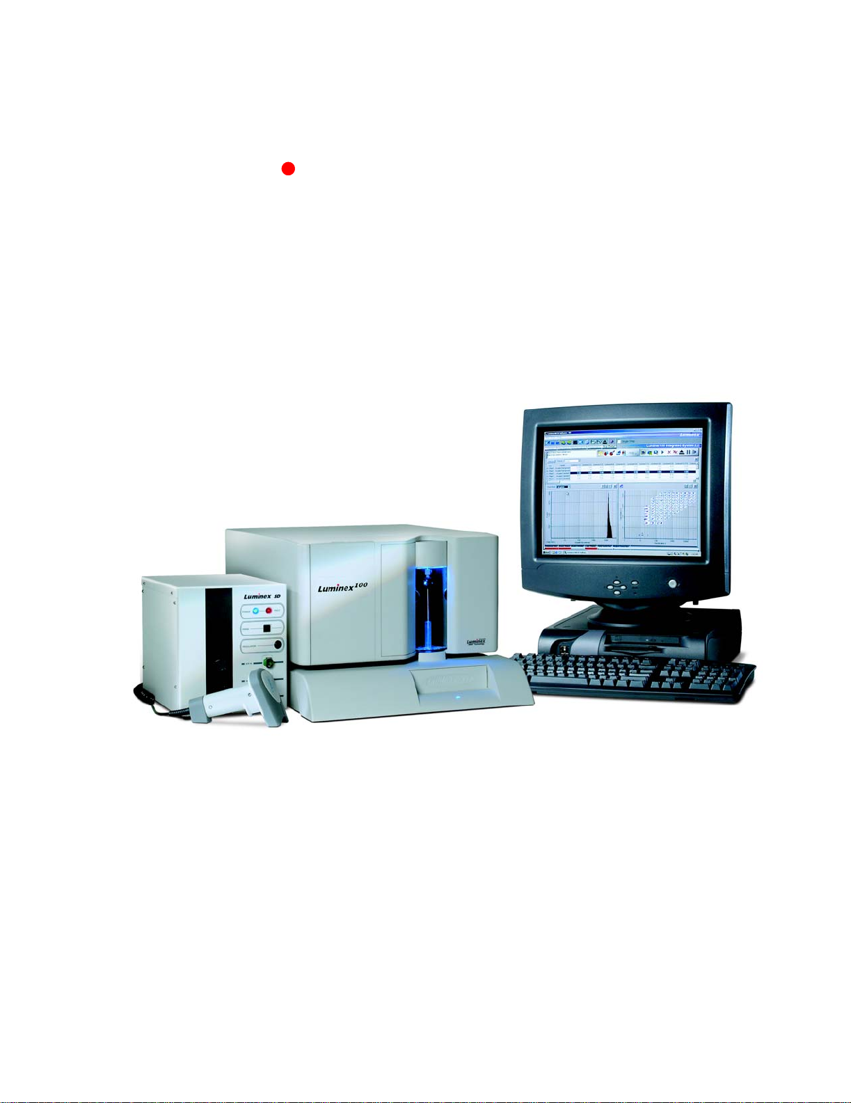
The Luminex 100 IS 2.3 system is a benchtop system consisting of
the Luminex 100 analyzer, computer, monitor, keyboard, mouse,
Luminex XY Platform instrument (Luminex XYP™), Luminex
Sheath Delivery System (Luminex SD™), software, barcode reader,
sheath and waste containers, and xMAP technology reagents.
of xMAP technology-based laboratory tests, measuring biomolecular
reactions on the surface of xMAP microspheres. The system is
intended For In-V itro Di agnostics Use for Export Only.
Page 16

Luminex 100 IS User Manual Version 2.3 xMAP Technology
Technical Support Luminex Technical Support representatives are ready to help you,
particularly when the system or software cause any questions or
problems. If the question or problem relates to materials from the
assay kit, you should contact the kit provider directly.
Luminex Technical Support is available to users in the U.S. and
Canada by calling 1-877-785-BEAD (-2323) between the hours of
7:00 a.m. and 7:00 p.m. Central Time, Monday through Friday.
Users outside of the U.S., Canada, Europe can contact us at +1 512381-4397 between the hours of 7:00 a.m. to 7:00 p.m. Central Time,
Monday through Friday. Inquiries may also be sent by email to
support@luminexcorp.com.
Luminex Technical Support is also a vaila ble to users in Europe by
calling +31-162408333 between the hours of 8:30 and 5:30, Central
European Time, Monday through Friday. Email inquiries in Europe
can be sent to supporteurope@luminexcorp.com.
Luminex Website Additional information is available on the Luminex website. Search
on the desired topic or navigate through menus. Also, review the
website’s FAQ section.
To access Luminex website FAQ section:
In your browser’s address field, enter:
http://luminexcorp.custhelp.com. This address takes you
directly to the FAQ section.
1 - 2 PN 89-00002-00-072 Rev. C
Page 17
Safety
2
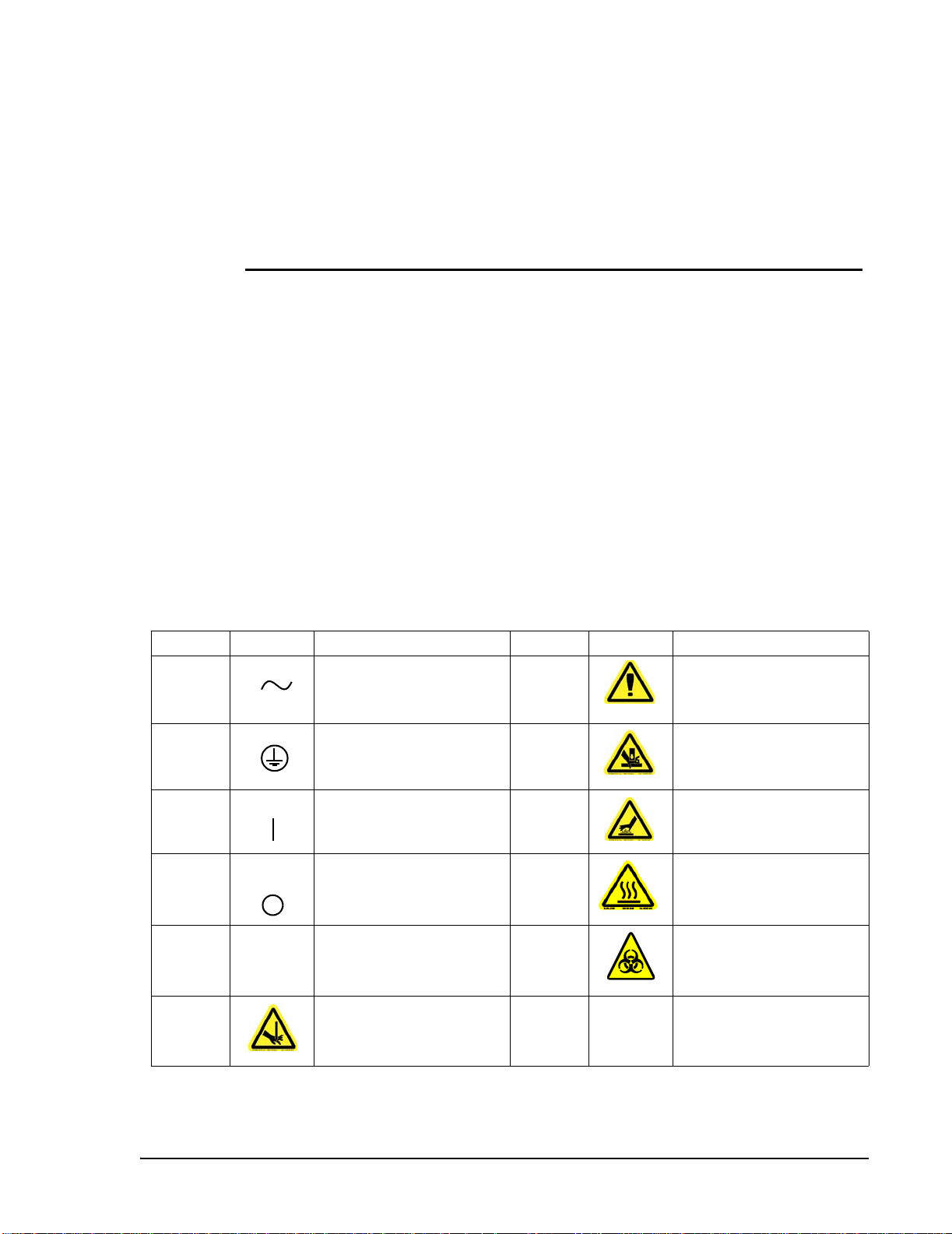
Symbols Please become familiar with the information in this chapter before
using the equipment. Do not perform procedures on your Luminex
100 IS 2.3 system that are not specifically contained in this manual,
unless you are directed to do so by Luminex Technical Support.
These symbols describe warnings, cautions, and general information
used in the operation of this instrument. These symbols are further
defined under “Safety Precautions.”
Number Symbol Description Number Symbol Description
1 Alternating current (ac) 7 Warning (refer to manual)
2 Protective ground 8 Warning (refer to manual)
3 On 9 Warning (refer to manual)
4 Off 10 Warning (refer to manual)
5 SN Serial number 11 Warning (refer to manual)
6 Warning (refer to manual)
PN 89-00002-00-072 Rev. C 2 - 1
Page 18
Luminex 100 IS User Manual Version 2.3 xMAP Technology
Warnings and Notes Informational notes and warnings appear in this manual.
Note: A note provides general helpful information. No safety or
performance issues are involved.
Caution: This message is used in cases where the hazard is minor or
only potential hazard is present. Failure to comply with the caution
may result in potentially hazardous conditions.
Warning: This message is used in cases where danger to the
operator or to the performance of the instrument is present. Failure to
comply with the warning may result in incorrect performance,
instrument failure, invalid results, or hazard to the operator.
Danger: This message is used in cases where significant risk of
serious injury or death is present.
Safety Precautions Read the following safety information before setting up or using the
Luminex 100 IS 2.3 system. A user should be present during
operation. This system contains electrical, mechanical, and laser
components which, if handled improperly, are potentially harmful. In
addition, biological hazards may be present during system operation.
Therefore, we recommend that all system users become familiar with
the specific safety advisories below, in addition to adhering to
standard laboratory safety practices. The protection provided by the
equipment may be impaired or the warranty voided if the system is
used in a manner not specified by the instructions or by Luminex
Corporation.
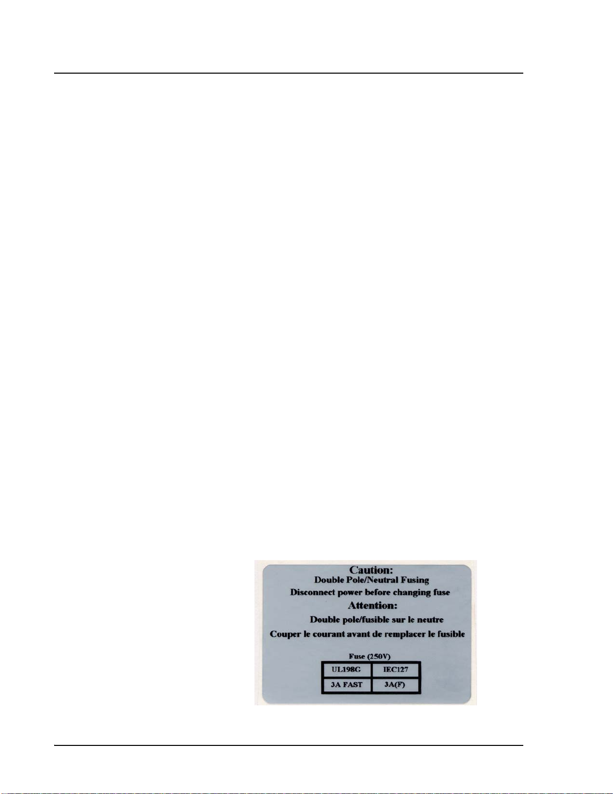
This caution label appears on the back of the Luminex 100 analyzer
and on the Luminex XYP instrument.
.
Figure 2-1 Fuse Caution Label
2 - 2 PN 89-00002-00-072 Rev. C
Page 19
xMAP Technology Safety
Do not perform any maintenance or cleaning of the system’s
electrical components, with the exception of replacing fuses.
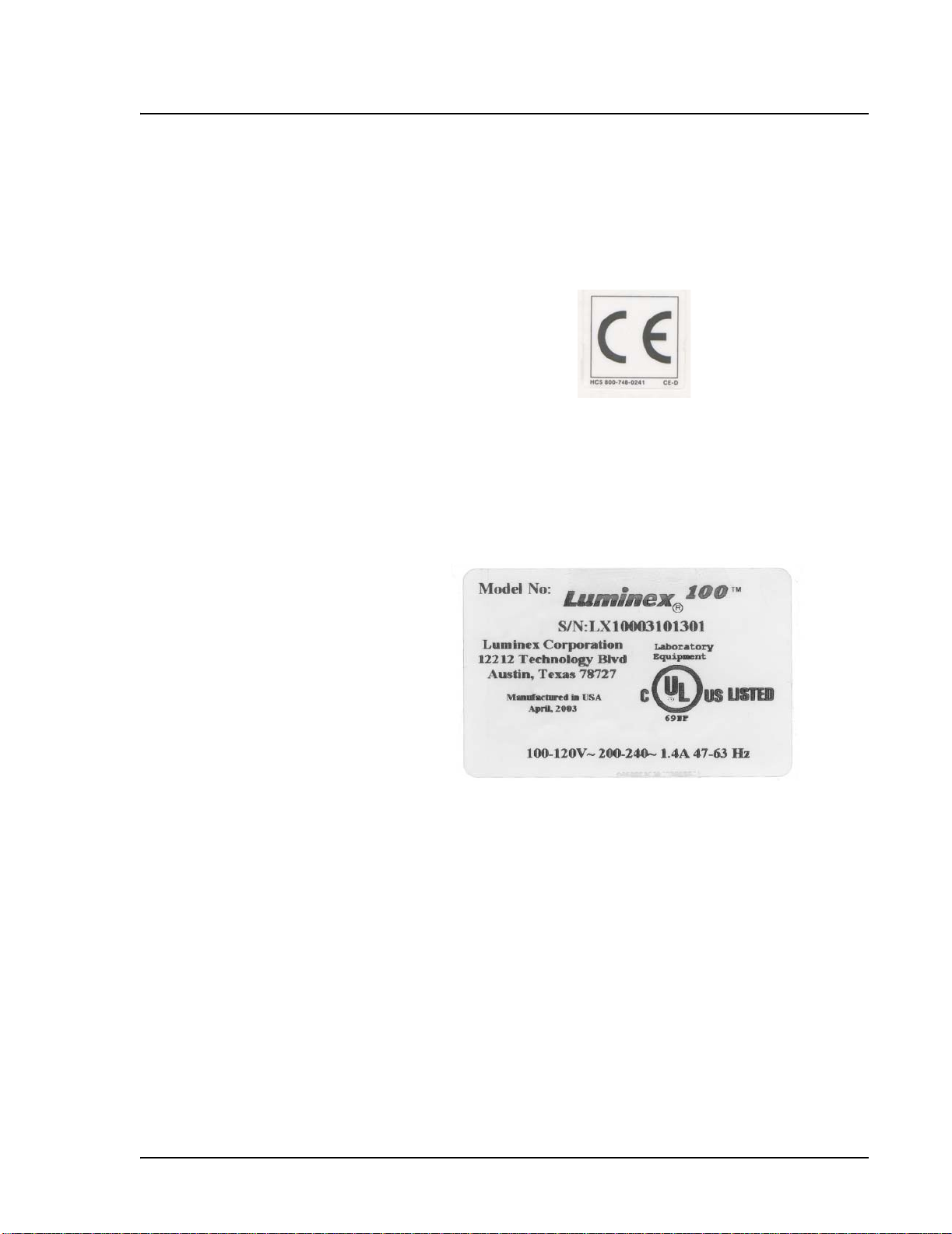
This label appears on the back panel of the Luminex 100 analyzer
and on the back panel of the Luminex XYP instrument.
Figure 2-2 CE Label
The Luminex 100 analyzer and the Luminex XYP instrument
comply with European Union (EU) safety requirements and,
therefore, may be marketed in the Europe Single Market.
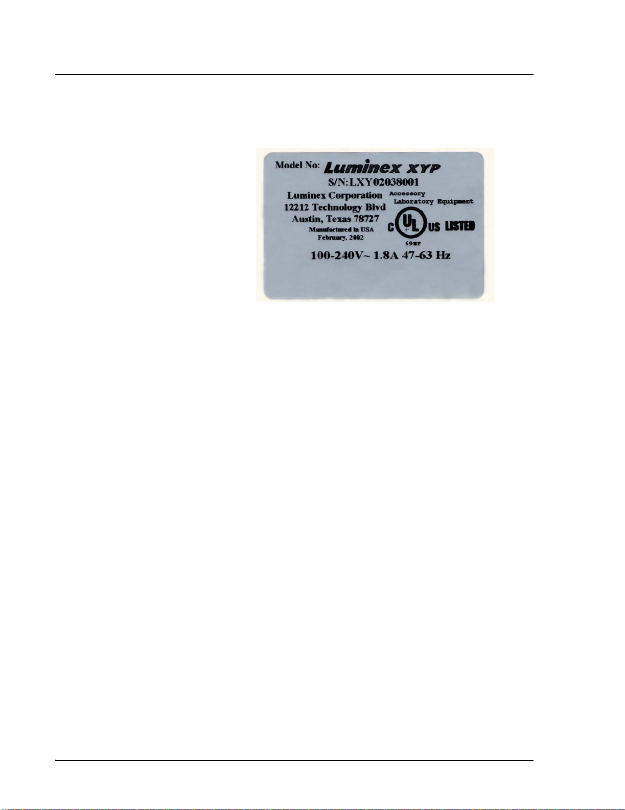
This voltage label appears on the back of the Luminex 100 analyzer:
Figure 2-3 Luminex 100 Serial Number Label
The Luminex 100 analyzer has been tested by Underwriter
Laboratories, Inc.® (UL).
PN 89-00002-00-072 Rev. C 2 - 3
Page 20
Luminex 100 IS User Manual Version 2.3 xMAP Technology
The following label appears on the back of the Luminex XYP
instrument.
Figure 2-4 Luminex XYP Serial Number Label
The Luminex XYP instrument has been tested by UL.
FCC Label This equipment has been tested and found to comply with the limits
for a Class B digital device, pursuant to part 15 of the FCC Rules.
These limits are designed to provide reasonable protection against
harmful interference in a residential installation. This equipment
generates, uses and can radiate radio frequency energy and, if not
installed and used in accordance with the instructions, may cause
harmful interference to radio communications. However, there is no
guarantee that interference will not occur in a particular installation.
If this equipment does cause harmful interference to radio or
television reception, which can be determined by turning the
equipment off and on, the user is encouraged to try to correct the
interference by one or more of the following measures:
• Reorient or relocate the receiving antenna.
• Increase the separation between the equipment and the
receiver.
• Connect the equipment into an outlet on a circuit different
from that to which the receiver is connected.
• Consult the dealer or an experienced radio/TV technician for
help.
Fluidics This system contains fluidics. In the event of a fluid leak, turn off all
power to the system and disconnect all power cords. Remember that
the on/off switch is not a disconnect means; the power cord must be
removed from the outlet. Contact Luminex Corporation for further
information.
2 - 4 PN 89-00002-00-072 Rev. C
Page 21
xMAP Technology Safety
You must monitor waste levels manually. Do not allow the waste
container to overflow! Empty the waste container each time the
sheath fluid container is filled. Do not place the waste container on
top of the instrument.
Warning: If biological samples have been tested with the system,
use your standard laboratory safety practices when handling
system waste.
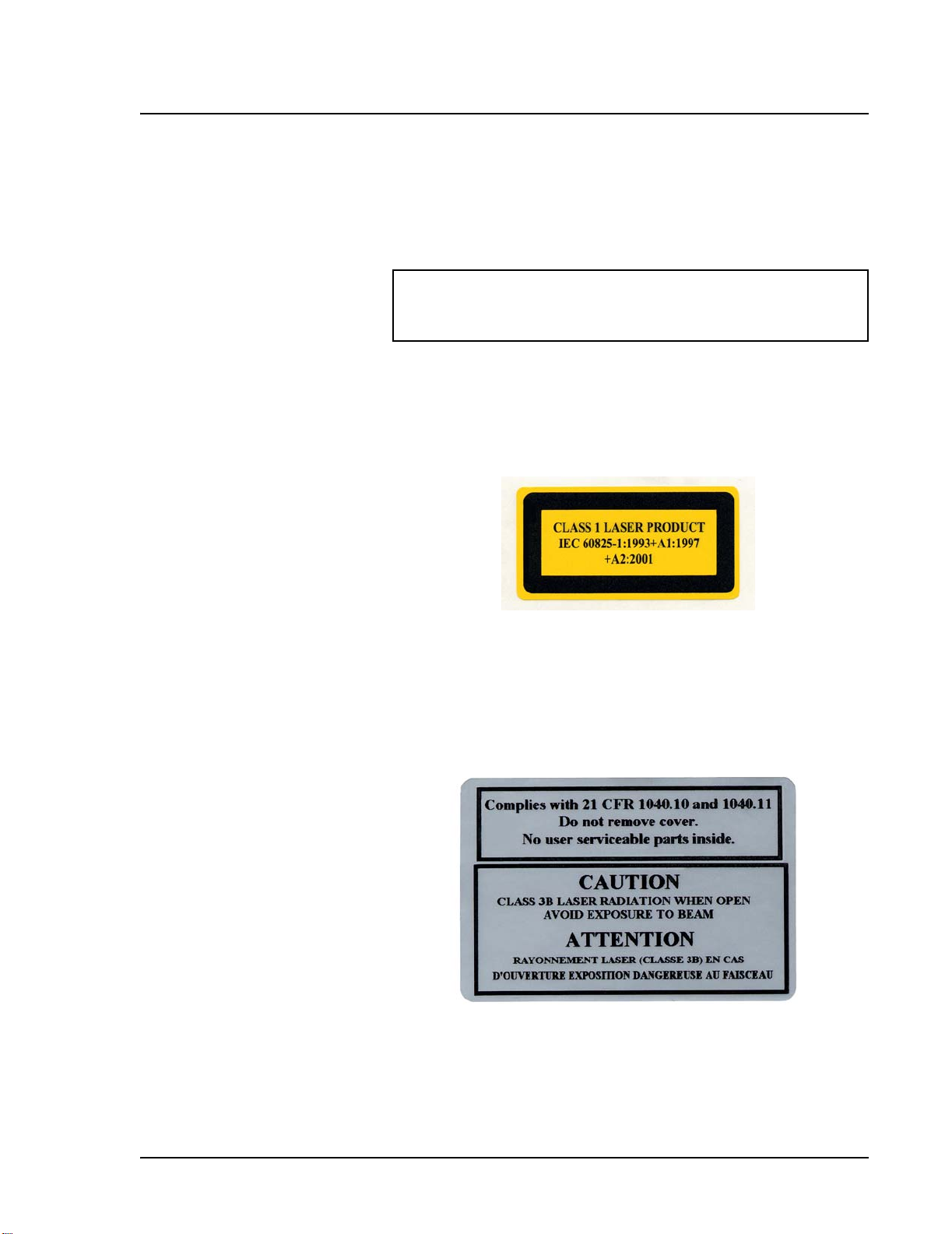
Luminex 100 Analyzer Laser
The Luminex 100 IS system classifies per FDA 21 CFR 1040.10 and
1040.11 as a Class II laser product consisting of a Class I laser
product (Luminex 100 analyzer) and a Class II laser product
(barcode reader).
Figure 2-5 Laser Product Class Label
United States and international regulations require the following
warnings to appear on the instrument during operation and
maintenance.
This label appears on the back panel of the Luminex 100 analyzer.
Figure 2-6 Laser Radiation Caution Label
Under NO circumstances should you remove the Luminex 100
analyzer cover! When performing routine maintenance, turn power
to the Luminex 100 analyzer OFF and the disconnect the power cord.
PN 89-00002-00-072 Rev. C 2 - 5
Page 22
Luminex 100 IS User Manual Version 2.3 xMAP Technology
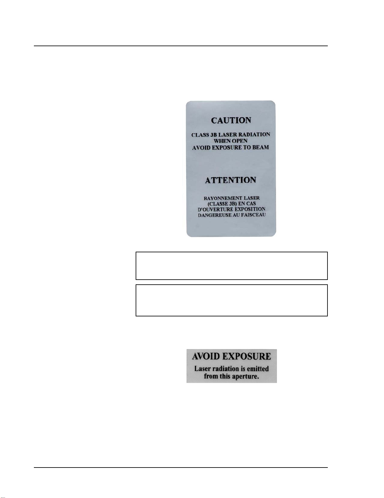
All laser apertures are located within the Luminex 100 analyzer and
are contained within a protective housing. This label appears on the
optics cover within the Luminex 100 analyzer.
Figure 2-7 Laser Class Label
Warning — Use of controls or adjustments or performance of
procedures other than those specified herein may result in
hazardous radiation exposure.
Attention — L’utilisation des commandes ou réglages ou
l’exécution des procédures autres que celles spécifiées dans les
présentes prescriptions peuvent entraîner d’une exposition à un
rayonnement dangereux.
This label appears above the laser apertures located inside the optics
enclosure inside the Luminex 100 analyzer.
Figure 2-8 Avoid Exposure Label
2 - 6 PN 89-00002-00-072 Rev. C
Page 23
xMAP Technology Safety
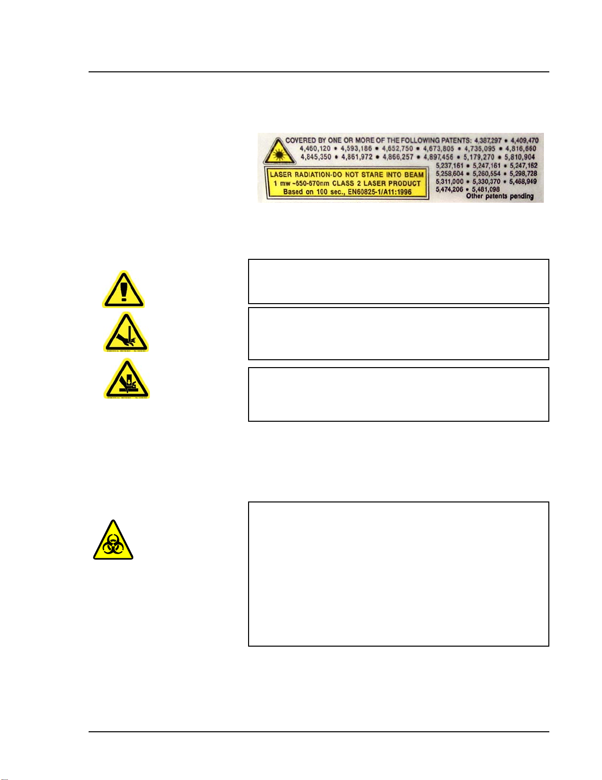
Barcode Reader Laser This label is attached to the barcode reader.
Figure 2-9 Barcode Reader Laser Label
Do not stare into the beam or shine it into other people’s eyes.
Mechanical
Warning: During operation, this system contains exposed,
moving parts. Risk of personal injury is present. Observe all
warnings and cautions.
Warning: During operation, this system contains exposed,
moving parts which could result in puncture hazard. Risk of
personal injury is present. Keep hands and fingers away from the
Luminex XYP instrument slot during operation.
Note: Access doors must be
closed while operating the
Luminex 100 analyzer; the
operator must be present during
operation.
Biological
Warning: During operation, this system contains exposed,
moving parts which could result in pinch point hazard. Risk of
personal injury is present. Keep hands and fingers away from the
Luminex XYP instrument slot during operation.
Warning: Hum an and animal samples ma y cont ain biohazardo us
infectious agents.
Where exposure (including aerosol) to potentially biohazardous
material exists, follow appropriate biosafety procedures and use
personal protective equipment, such as gloves, gowns, laboratory
coats, face shields, or mask and eye protection, and ventilation
devices.
Observe all local, state, and federal biohazard handling
regulations when disposing of biohazardous waste material.
PN 89-00002-00-072 Rev. C 2 - 7
Page 24
Luminex 100 IS User Manual Version 2.3 xMAP Technology
Heat
Warning: The heater plate of the Luminex XYP instrument may
be hot and could cause personal injury if touched. Do not touch
the heater plate.
Blue Indicator Light
The blue light above the Luminex 100 analyzer sample arm indicates
the on/off status of the Luminex 100 analyzer, and is harmless. The
blue light-emitting diode (LED) does not emit light in the UV
spectrum.
2 - 8 PN 89-00002-00-072 Rev. C
Page 25

xMAP Technology Safety
Decontaminating the Luminex 100 Analyzer for Return Shipment
Note: It is the user’s
responsibility to
decontaminate the
analyzer before
shipment.
Luminex Technical Support will give you a Return Material
Authorization (RMA) number if they direct you to return the system.
They will explain how to return the system according to Luminex
procedures.
The accessible surfaces and the internal fluidics system must be
sanitized and decontaminated before returning the analyzer. This is
particularly important when biohazardous samples have been run.
Make a copy of this page to fill out and return with the system.
Complete the following checklist, signed and dated, and return it
with the Luminex 100 analyzer.
1. Remove all specimens, disposables, and reagents from the system.
2. Disconnect the sheath line going from the SD system to the analyzer.
3. Connect a sheath bottle filled with a solution of 10% to 20% household
bleach and water to the analyzer.
4. Sanitize the system using the Sanitize command on the main screen of
the system. Follow this by washing twice with distilled water.
5. Disconnect the system from AC power by turning off the power switch
on the rear of the system, then unplugging the analyzer power cord
from the wall source.
6. Disconnect the SD system and waste and sheath containers.
7. Rinse the waste container with 10% to 20% household bleach solution
and drain.
8. Wash all exterior surfaces with a mild detergent, followed by a 10% to
20% bleach solution.
9. Open both front doors of the analyzer and clean all accessible surfaces
with mild detergent followed by a 10% to 20% bleach solution.
10. Pack the system within a biohazard bag, place it in the corrugated box,
then insert it in its original packaging or an approved shipping
container. Attach this checklist to the top of the corrugated box prior to
packaging in the crate.
Was there an internal leak in the system? Yes No
Print Name:
Signature:
Date: Instrument Serial No.
PN 89-00002-00-072 Rev. C 2 - 9
Page 26

Luminex 100 IS User Manual Version 2.3 xMAP Technology
2 - 10 PN 89-00002-00-072 Rev. C
Page 27

The System
3
Theory of Operation Luminex 100 IS technology is based on flow cell fluorometry with
Luminex-developed innovations. The fluidics, optics, robotics,
temperature control, software, and xMAP microspheres work
together to enable simultaneous analysis of up to 100 analytes in a
single test sample. Assay analysis requiring temperature control is
provided through the Luminex XYP instrument heater block.
There are two fluidics paths in the Luminex 100 analyzer. The first
path involves a syringe-driven mechanism that controls the sample
uptake. This mechanism permits small sample uptake volumes from
small reaction volumes. The syringe-driven system transports a
specified volume of sample from a sample container to the cuvette.
The sample is injected into the cuvette at a steady rate for analysis.
Following analysis, the sample path is automatically purged with
sheath buffer by the second fluidics path. This process removes
residual sample within the tubing, valves, and probe. The second
fluidics path is driven by positive air pressure and supplies sheath
fluid to the cuvette and sample path.
Sheath fluid is the delivery medium of the sample to the optics
component. The analysis sample is acquired using a sample probe
from a 96-well microtiter plate via the Luminex XYP instrument and
injected into the base of the cuvette. The sample then passes through
with sheath fluid at a reduced rate resulting in a narrow sample core
to ensure that each microsphere is illuminated individually. The
sample injection rate is such that the xMAP microspheres are
introduced to the optics path as a series of single events. The
Luminex SD system lets you run samples continuously without
refilling sheath bottles. It automatically draws sheath from a non
pressurized bulk sheath container to constantly maintain a reservoir
PN 89-00002-00-072 Rev. C 3 - 1
Page 28

Luminex 100 IS User Manual Version 2.3 xMAP Technology
of pressurized sheath fluid. A single 20 liter sheath container
provides enough fluid for 48 hours or more of normal operation.
The optics assembly consists of two lasers. One laser excites the dye
mixture inside the xMAP microspheres and the second laser excites
the fluorosphere bound to the surface of the xMAP microspheres.
Avalanche photo diode detectors measure the excitation emission
intensities of the color coding classification dye mixtures inside the
xMAP microspheres and a photomultiplier tube detects the excitation
emission intensity of the reporter molecule bound to the surface of
the xMAP microspheres. High speed digital signal processors and
advanced computer algorithms provide analysis of the xMAP
microspheres as they are processed through the Luminex 100
analyzer. Results of the analyses are processed and provided in a
report format.
Hardware The Luminex 100 IS system includes the following hardware:
• Luminex 100 analyzer
• Computer (PC), monitor, and accessories
• Luminex XYP instrument
• Luminex Sheath Delivery System (Luminex SD™)
• Power cables
• Alignment guide
• Two long sample probes
• Luminex XYP instrument sample probe
• Reservoir
•Shield
•Heater block
• Sheath fluid container
• Waste container
• Sheath fluid line
• Air line
• Sheath fluid intake line
• Communications: 1 serial communication cable
• Communications: 1 USB communication cable
• Communications: 1 CANBUS communication cable (short
cable)
• Barcode reader
• Sample probe height alignment kit
• 3/32 Hexdrive, Balldriver wrench
3 - 2 PN 89-00002-00-072 Rev. C
Page 29

xMAP Technology The System
xMAP Technology Reagents
Required Laboratory Reagents
Luminex 100 IS 2.3 Software
• Classification calibration microspheres (CAL1)
• Reporter calibration microspheres (CAL2)
• Classification control microspheres (CON1)
• Reporter control microspheres (CON2)
• Sheath fluid
• Household bleach
• 70% isopropanol or 70% ethanol
• Mild detergent
Luminex 100 IS 2.3 software provides complete control of the
system and performs data analysis. Your Luminex 100 IS 2.3 system
is preloaded with the Luminex software. However, we supply a
software CD should you need to reinstall the software.
This software requires a dedicated system. Unauthorized additional
software is prohibited and may result in improper operation of the
system.
Luminex 100 IS Performance Specification
Speed • USB communications link for fast data transfer
• Automatic transfer of assay templates and new reagent
information into the system via a large capacity read/write CD
• Installation: < 4 hours
• System calibration: < 10 minutes
• System controls: < 10 minutes
• Barcode reader entry of sample IDs
• Automatic post-analysis
• Analyze one 96-well plate/hour depending on manufacturer’s kit
• Up to 100 xMAP microsphere sets per sample
• Sheath flowrate: 90 µL/sec ± 5 µL
• Sample injection rate into detector area: 1 µL/sec ± 0.05 µL
• System warmup: 30 minutes. Systems that remain inactive for at
least four hours will require a warm-up to restart the lasers. After
PN 89-00002-00-072 Rev. C 3 - 3
Page 30

Luminex 100 IS User Manual Version 2.3 xMAP Technology
acquiring sample, running system calibrators, running system
controls, and warming up the instrument, the system resets the
four-hour internal clock.
Accuracy and Precision • Sample uptake volume: ± 5%
• Classification of xMAP microspheres: > 80%
• Misclassification of xMAP microspheres: ≤ 2% - may vary by
xMAP microsphere product lines. Refer to the specific product
information sheet for further details.
• Temperature control: 0°C to + 2°C of target
• Internal sample carry over: < 0.9%
• Soluble background fluorescence emission at 575 nm
automatically subtracted from fluorescence intensity values
Sensitivity • Detect 1000 fluorochromes phycoerythrin (PE) per xMAP
microsphere
• Reporter channel dynamic range: 3.5 decades of detection
Capacity The specifications below reflect minimum capacity values:
• 10 GB hard drive
• 100 MB read/write CD ROM
• Analyze multiple 96-well plates per batch
• Analyze multiple assay templates per plate
• Distinguish a minimum of 1 to a maximum of 100 unique xMAP
microsphere sets in a single sample
• Detect and distinguish surface reporter fluorescence emissions at
575 nm on the surface of 1-100 unique xMAP microspheres sets
in a single sample
• S ample core: 15-20 µm core at 1 µL/sec. sample inject rate
• Maintain samples at a constant temperature from 35°C to 55°C
(95°F to 131°F)
• Automatic sampling from a 96-well plate
• Start sampling from any well position
• Sheath container and waste container hold enough volume to run
up to two 96-well plates between refills
• M icrotiter plates with 96 wells must be compatible with the
Luminex XYP instrument plate holder. The following microtiter
plate types are compatible with the Luminex XYP instrument
plate holder: flatbottom, conical, round, filter bottom, half plates
[overall height no more than 0.75” (19 mm)], any color
• M icrotiter plates with 96 wells must be compatible with
Luminex XYP instrument heater block temperature from 35°C to
3 - 4 PN 89-00002-00-072 Rev. C
Page 31

xMAP Technology The System
55°C (95°F to 131°F) when performing heated assays and using
the heater block
Luminex 100 Analyzer General
• Indoor use only
• Operating temperature: 15°C to 30°C (59°F to 86°F)
• Humidity: 20% to 80%, noncondensing
• Altitude: Operation up to 2400 m (7874 ft.) above mean sea level
• Physical dimensions: 43 cm (17 inches) W x 50.5 cm (20 inches)
D x 24.5 cm (9.5 inches) H
• Weight: maximum of 25 kg (60 lbs.)
• UL installation category: UL Installation Category II, as defined
in Annex J of UL 61010A-1
• Pollution degree: UL Pollution Degree 2, as defined in Section
3.7.3.2 of UL 61010A-1
• Shipping and storage: The allowable shipping and storage
temperature and humidity ranges are 0°C to + 50°C and 20-80%
noncondensing, respectively
• Input voltage range: 100 - 120 V~ ± 10%, 1.4 Amp, and 200-240
V~ ± 10%, 0.8 Amp, 47-63 Hz.
• AC inlet fuse: 3 Amp, 250 V~, fast acting
Optics • Reporter laser: 532 nm, nominal output 10-15 mW, maximum
500 mW, frequency-doubled diode; mode of operation,
continuous wave (CW)
• Classification laser: 635 nm, 9.1 mW ± 6%, maximum output 25
mW, diode; mode of operation, continuous wave (CW)
• Reporter detector: Photomultiplier tube, detection bandwidth of
565-585 nm
• Classification detector: Avalanche photo diodes with
temperature compensation
• Doublet discrimination detector: Avalanche photo diodes with
temperature compensation
Fluidics • Sheath flow rate 90 µL ± 5 µL/second
• Cuvette: 200 micron square flow channel
• S ample injection rate: 1 µL/second
• Sample uptake volume: 20-200 µL
Electronics • Reporter channel detection: A/D resolution 14 bits
• Communications interface: USB
• L uminex XYP instrument, communications interface: RS 232
PN 89-00002-00-072 Rev. C 3 - 5
Page 32

Luminex 100 IS User Manual Version 2.3 xMAP Technology
Luminex XYP Instrument General
Luminex SD System General
• Ambient temperature: 15°C to 30°C (59°F to 86°F)
• Humidity: 20% to 80%, noncondensing
• Altitude: operation up to 2400 m (7874 ft) above mean sea level
• Physical dimensions: 44 cm (17.25 inches) W x 60 cm (23.5
inches) D x 8 cm (3 inches) H
• Weight: 15 kg (33 lbs.)
• UL installation category: UL Installation Category II, as defined
in Annex J of UL 61010A-1
• Pollution degree: UL Pollution Degree 2, as defined in Section
3.7.3.2 of UL 61010A-1
• Heater operating range: 35°C to 55°C (95°F to 131°F) with
tolerance 0°C to +2°C
• Input voltage range: 100-240 V~ ± 10%,1.8 Amps, 47-63 Hz
• AC inlet fuse: 3 A, 250 V~, fast acting
• Ambient temperature: 15°C to 30°C (59° to 86°F)
• Humidity: 20% to 80%, noncondensing
• Altitude: designed to operate at up to 2400m (7874 feet) above
mean sea level
• Physical dimensions: 20 cm (8 inches) W x 30 cm (11.75 inc he s )
D x 24.75 cm (9.75 inches) H
• Weight: 9 kg (20 lbs)
• UL installation category: UL Installation Category II, as defined
in Annex J of UL 61010A-1
• Pollution degree: UL Pollution Degree 2, as defined in Section
3.7.3.2 of UL 61010A-1
• Input voltage range: 100-240 V~ ± 10%, 0.4 Amps, 47-63 Hz
• AC inlet fuse: 2 Amp, 250 V~, time lag
PC Specifications For systems using a PC, A Dell OptiPlex GX280 or Dell Optiplex
GX520 (or newer PC) is shipped with the Luminex 200 system. For
systems using a laptop, a Dell D610 Notebook is shipped with the
system. Microsoft
The power requirements are 115-230 V~, 6 Amps, 50-60 Hz
For updated information regarding the PC, notebook, or operating
system, go to http://www.luminexcorp.com, then click on the
Support link to open the FAQ list.
3 - 6 PN 89-00002-00-072 Rev. C
® Windows® XP is pre-installed on the computers.
Page 33

xMAP Technology The System
Recommended Additional Equipment
Uninterruptible
Power Supply
(UPS)
Surge Protector If you do not use a UPS, use a surge protector. Choose a protector
Printer Printer, HP LaserJet 2300 or available equivalent
Barcode Labels Use the Code 128 barcode label type when scanning barcode labels
Vortex VWR product number 58816-121: Speed range 0-3200 rpm or
Luminex highly recommends using an uninterruptible power supply
(UPS) to protect your system from power outages. Choose one that
can provide 1050 Watts for at least 45 minutes. The UPS should be
UL listed, CSA certified, and CE marked when used internationally.
that meets your needs. Factors to consider include electrical
environment, endurance, suppressed voltage rating, and method of
protection. It should have six outlets, rated at least 1500 Watts, and
be UL listed, CSA certified, CE marked for nondomestic use when
used internationally .
into the system as patient identities.
equivalent
Bath Sonicator Cole-Parmer® product number 08849-00: Operating frequency 55
kHz or equivalent
System Overview The system consists of three subsystems: electronic, fluidic, and
optical. The following section describes the user-accessible
components of each subsystem.
Electronics
Power Input
Module
Communications
Ports(SB9-PIN)
Luminex 100
Analyzer
Ventilation Filter
The power input modules contain the on/off switch and fuses.
The communications port connects the Luminex 100 analyzer or the
Luminex XYP instrument to the computer, and the Luminex SD
system to the Luminex 100 analyzer.
Located on the bottom of the Luminex 100 analyzer, the filter must
be checked and cleaned as necessary. For proper ventilation, do not
obstruct the area below and allow at least two inches (5 cm) of
clearance around the Luminex 100 analyzer.
PN 89-00002-00-072 Rev. C 3 - 7
Page 34

Luminex 100 IS User Manual Version 2.3 xMAP Technology
Luminex XYP
Instrument
Ventilation Filter
1
2
3
The XYP instrument ventilation filter cleans the air that cools the
internal parts of the Luminex XYP instrument. See Figure 3-1.
4
1
1. Air intake filter access door 5. Communication Ports (DB9)
2. Power Switch 6. XYP Communication Port (DB9)
3. Power Input Module 7. Analyzer ventilation filter
4. XYP Ventilation Filter
5 7
6
(on bottom of analyzer)
Fluidics
Figure 3-1 Back of the Luminex 100 Analyzer and Luminex XYP
Instrument
Sample Arm The sample arm transports the sample from the sample tube to the
cuvette. The carriage drops to the microtiter well for sample
retrieval.
Luminex XYP
Instrument Sample
A stainless steel sample probe acquires the sample. A shorter probe
is provided for shipping and troubleshooting.
Probe
Warning: During operation, this system contains exposed moving
parts that can result in a puncture hazard. Risk of personal injury
is present. Keep hands and fingers away from the sample probe.
The shield should be in place.
Cheminert® Fitting This fitting attaches the Luminex 100 analyzer sample arm tubing to
the sample arm. Disconnect this fitting when you remove the sample
probe. See Figure 3-2.
3 - 8 PN 89-00002-00-072 Rev. C
Page 35

xMAP Technology The System
The alignment guide directs the sample probe into the Luminex XYP
instrument.
1
2
3
4
5
1. Cheminert Fitting
2. Sample Arm
3. Luminex XYP Instrument Sample Probe
4. Shield
5. Alignment Guide
Figure 3-2 Cheminert Fitting
Access Doors The Luminex 100 analyzer has three access doors. Two of the access
doors are on the front, and the third is on the back. The front left
access door supplies access to the sheath filter. The front center
access door supplies access to the syringe. The rear access door
supplies access to the air intake filter. See Figure 3-3 and Figure 3-4.
1
2
1. Left door, access to service panel 2. Center door, access to syringe
Figure 3-3 Luminex 100 Analyzer Access Doors
PN 89-00002-00-072 Rev. C 3 - 9
Page 36

Luminex 100 IS User Manual Version 2.3 xMAP Technology
Air Intake Filter A replaceable air intake filter cleans the air used to pressurize sheath
fluid. This filter is enclosed behind an access door located on the
back of the Luminex 100 analyzer. See Figure 3-4.
Figure 3-4 Air Intake Filter
Syringe The syringe delivers a sample from the 96-well microtiter plate to the
cuvette. See Figure 3-5.
1
2
1. Syringe Seal 2. Syringe
Figure 3-5 Syringe and Syringe Seal
3 - 10 PN 89-00002-00-072 Rev. C
Page 37

xMAP Technology The System
Sheath Filter The sheath filter removes particles greater than ten microns in
diameter from the sheath fluid. See Figure 3-6.
Figure 3-6 Sheath Filter
Air, Waste, and
Sheath Fluid
Connectors
The air, waste, and sheath connectors, located on the left side of the
analyzer, connect to the SD system and waste fluid containers using
clear tubing. The air connector is green, the sheath fluid connector is
blue, and the waste fluid connector is orange. See Figure 3-7.
.
1
1. Sheath fluid connector (blue)
2. Air connector (green)
3. Waste connector (orange)
Figure 3-7 Air, Waste, and Sheath Fluid Connectors
2
3
PN 89-00002-00-072 Rev. C 3 - 11
Page 38

Luminex 100 IS User Manual Version 2.3 xMAP Technology
Luminex Sheath
Delivery System
Note: If you are not using the SD
system, sheath fluid levels must
be monitored manually. Check the
sheath fluid level before st ar ting a
run or procedure.
Waste Fluid
Container
For proper operation, place the Luminex SD system at the same level
as the base of the Luminex XYP instrument. Do not put it on top of
the Luminex 100 analyzer.
Warning: If biological samples have been tested with the
system, use your standard laboratory safety practices.
The waste fluid container receives waste from the system. The waste
container should not be placed on top of the instrument.
Caution: Waste levels must be manually monitored. Do not
allow the waste container to overflow!
.
Optical The optical system consists of the optical assembly and the excitation
lasers. The optical assemblies do not require manual adjustment by
the user.
xMAP Technology Reagents
The xMAP technology reagent system consists of classification
calibration microspheres, reporter calibration microspheres,
classification control microspheres, and reporter control
microspheres.
3 - 12 PN 89-00002-00-072 Rev. C
Page 39

4
Basic Concepts
Background Information
xMAP technology is a versatile system that measures soluble
analytes. The Luminex 100 IS system performs simultaneous,
discrete measurements of multiple microsphere-based reactions from
a single specimen aliquot. For more conceptual information, refer to
Practical Flow Cytometry, 3rd edition, by Howard M. Shapiro, M.D.
(New York: Wiley-Liss Inc., 1995).
Fluidics There are two fluidic paths in the Luminex 100 analyzer. The first
path involves a syringe-driven mechanism that controls the sample
uptake. This mechanism permits small sample uptake volumes from
small reaction volumes. The syringe-driven system transports a
specified volume of sample from a sample container to the cuvette.
The sample is injected into the cuvette at a steady rate for analysis.
Following analysis, the sample path is automatically purged with
sheath fluid by the second fluidics path. This process effectively
removes residual sample within the tubing, valves, and probe.
Approximately 160 µL of sheath fluid is dispelled into each well
following sample acquisition. The second fluidics path is driven
under positive air pressure and supplies sheath fluid to the cuvette
and sample path.
Excitation The excitation system in the Luminex 100 analyzer involves two
solid-state lasers. A reporter laser excites fluorescent molecules
bound to biological reactants at the xMAP microsphere surface, and
a classification laser excites fluorochromes embedded in the xMAP
microsphere. The lasers illuminate the xMAP microspheres as they
flow single-file through the cuvette. RP1 refers to the excitation
wavelength. CL1 and CL2 refer to the dyes embedded in the
microsphere. DD refers to the channel that discriminates against
doublets based on size.
PN 89-00002-00-072 Rev. C 4 - 1
Page 40

Luminex 100 IS User Manual Version 2.3 xMAP Technology
Photodiodes and a photomultiplier tube receive fluorescent signals
from xMAP microspheres. The Luminex 100 analyzer digitizes the
waveforms and delivers the signals to a digital signal processor
(DSP). Proprietary algorithms function with the DSP to greatly
increase sensitivity.
xMAP Microspheres The xMAP microspheres are highly uniform, polystyrene particles
that have been crosslinked during polymerization for physical and
thermal stability. Varying amounts of fluorochromes embedded
within each xMAP microsphere give each xMAP microsphere set an
unique fluorescent signal. To ensure the stability of this signal, it is
essential to protect the microspheres from light. Follow the product
information sheet instructions for storage procedures for xMAP
microspheres and assay kits.
Calibrator xMAP microspheres are used to normalize the settings for
the reporter channel, both classification channels and the doublet
discriminator channel for the Luminex 100 analyzer.
The control xMAP microspheres are used to verify the calibration
and optical integrity of the system.
Software Overview This section provides a brief overview for using the Luminex 100 IS
2.3 software.
With the Luminex 100 IS 2.3 software, you work with assay kits
provided by a kit manufacturer. A template may be included with
each kit that is imported into the software. The template includes a
sequence of commands required for the assay.
Once you select the template, you enter sample data into a “batch.”
Sample input can be done quickly with either the keyboard or a
barcode scanner. A batch can include as many samples as you have
for the assay and can include multiple microtiter plates. You can
even group multiple batches together into a multi-batch for efficient
processing. You can process a batch immediately or choose to
archive the batch for testing later.
As testing proceeds through the plate, you will see the display update
to show the wells that have been processed. Progress is shown in
both graphic and tabular form.
4 - 2 PN 89-00002-00-072 Rev. C
Page 41

xMAP Technology Basic Concepts
System calibrators and controls are provided as part of the system.
Calibrate at least once monthly, when the delta calibration (dCAL)
temperature changes by ±3 degrees, or if the system is powered off
or moved. You must run system controls following calibration and as
often as you like to ensure that your system continues to operate
optimally.
The software provides you with a variety of reports.
• Analyte Reports provide batch results grouped by the test in a
batch.
• Patient Summary reports provide batch results grouped by each
patient or unknown in a batch.
• Clinical Patient reports provide a breakdown of samples
according to the test analysis with that sample.
• Maintenance Reports provide a history of all maintenance
operations performed during a specified period of time.
• Calibration Trend reports provide results of calibration
commands performed over a specified time period.
• System Control Trend Reports provide results of system controls
performed over a specified time period.
• Batch Summary Reports provide batch information in a sample
versus test grid format.
• Quality Control Reports track the trends of assay controls over a
period of time
These reports let you look at specific details regarding the samples
you process through the Luminex 100 IS 2.3 software and system
operation.
System tools help you monitor the system including a display
showing real-time system property values and a message log. Errors
are shown in the message log and also on your reports. You can even
add comments to specific results in some of these reports.
To keep track of your reagents, the Lum inex 100 IS 2.3 software
stores lot numbers, expected values, and expiration information.
A comprehensive set of self-diagnostic tests ensure that your system
is working correctly. These tests are performed at startup and can be
performed at any time. If any problem is detected, an error message
appears in the message log to inform you.
PN 89-00002-00-072 Rev. C 4 - 3
Page 42

Luminex 100 IS User Manual Version 2.3 xMAP Technology
4 - 4 PN 89-00002-00-072 Rev. C
Page 43

5
Using Luminex 100 IS 2.3 Software
This manual describes how to use the Luminex IS 2.3 software. It
includes a glossary and information regarding the CSV file setup.
The software user should have a basic familiarity with computers and
Microsoft® Windows®. Commands are often available through
more than one method, such as from the main menu bar, the toolbar,
or on different windows. However, each procedure in this manual
will describe only one method of accessing commands.
This chapter has the following sections:
• Main Window - This section describes the main window of the
Luminex IS 2.3 software, including tabs and commands. Use this
section to become familiar with the main functions of the
software.
• S econdary Windows - This section describes the secondary
windows in the Luminex IS 2.3 software, including the Analysis
Window and Batch Setup Window.
• Commands - This section describes the functions of the
commands in the Luminex IS 2.3 software.
• P rocedures - This section describes how to perform tasks using
the Luminex IS 2.3 software.
When using microtiter plates, use plates with wells that will hold at
least 185 µL (the extra 25 µL from the sample, plus an extra 160 µL
that is dispensed back into the well following acquisition).
Main Window The Luminex IS 2.3 software starts automatically when you log into
Windows.
When the first software User window opens, the Main window is
open, with the Home tab displayed, as shown in Figure 5-1
PN 89-00002-00-072 Rev. C 5 - 1
Page 44

Luminex 100 IS User Manual Version 2.3 xMAP Technology
.
1
2
3
4
5
1. Title bar 4. Tabs
2. Menu bar 5. Status bar
3. Tool bar
Figure 5-1. Luminex IS 2.3 Main Window
There are five major parts in the Main window: Title bar, Menu bar,
Tool bar, Tabs, and Status bar. A brief description of each of these
components is shown below.
The Title Bar displays the name of the software.
The Menu Bar contains three menus, File, Tools, and Help menu. A
more thorough description of the Menu is shown on page 5-3.
The Toolbar - has shortcut buttons for frequently-used commands. A
more thorough description of the Toolbar is shown on page 5-4.
There are five Tabs, organized by function. The tab that displays
when the software starts up is the Home tab. A more thorough
description of each of these tabs begins on page 5-4.
The Status bar displays the system status at the bottom of the main
window. A more thorough description of the Status bar is shown on
page 5-17.
5 - 2 PN 89-00002-00-072 Rev. C
Page 45

xMAP Technology Using Luminex 100 IS 2.3 Software
Menu Bar The menu bar contains the following menus: File Menu, Tools
Menu, and Help Menu.
File menu - contains the following commands:
• Import Template
•New Batch
• Open Batch
• Delete Batch
• Edit Patient List
• Open Incomplete Batch
• Batch Comment
• New Multi-Batch
• Open Multi-Batch
• Data Analysis
• Export Batch Data
• Print Report
•Exit
Tools menu - contains the following commands:
• Connect
• Disconnect
• Database Backup
• Database Restore
• Erase Database
• Update CAL Targets
• Update CON Targets
• New Assay Lot
• Options
•Cleanup
For information on each of these commands, see the Commands
section, beginning on page 5-31.
Help menu - this contains menu selections that open the online help
and describe the software and hardware.
• Contents opens the online help
• About the Device opens a dialog box that shows the version
and serial numbers of the Luminex instruments you are using.
• About the Software opens a dialog box that shows the
version of the Luminex Software you are using.
PN 89-00002-00-072 Rev. C 5 - 3
Page 46

Luminex 100 IS User Manual Version 2.3 xMAP Technology
Toolbar The shortcut buttons on the toolbar can be found in other locations in
the software. The Help button opens the online help. The Single Step
option on the toolbar allows you to pause the system in between each
command or sample acquisition within a batch.
4
1
3
2
1. Import Template 8. Print Report
2. New Batch 9. Connect to the Instrument
3. Open Batch 10. Disconnect from the Instrument
4. Create New Multi-Batch 11. Eject/Retra c t
5. Open Multi-Batch 12. Open Help File
6. Start Analysis 13. Single Step
7. Export Batch Data
7
65
8
9
10
11
12
Figure 5-2. Luminex IS 2.3 Toolbar
Tabs This section describes the tabs in the Main window.
Home tab This is the default tab. It is organized by the order of system use. It
contains a Favorites list and five button groups representing data
acquisition and maintenance categories.
1
13
2
1. Favorites List 2. Button Groups
Figure 5-3. Home Tab
5 - 4 PN 89-00002-00-072 Rev. C
Page 47

xMAP Technology Using Luminex 100 IS 2.3 Software
Favorites. You can use the Favorites list to create a customized list
of often-used commands and templates. Items appear in alphabetical
order for easy locating. For more information on setting up the
Favorites list, see page 5-42.
Button Groups. Button groups are grouped according to function.
•The Daily Startup group contains the Warmup, Prime,
Alcohol Flush, and Wash Commands. For more information
on daily startup, see page 5-43. For more information on the
commands, see the Commands section on page 5- 31.
•The Instrument Calibration group contains the CAL1,
CAL2, CON1, and CON2 buttons. For more information on
calibrating the system, see page 5-46. For more information
about these commands, see the Commands section on page 5-
31.
•The Batch Setup group contains the New Batch, New
Multibatch, and New Lot buttons. For more information on
creating and running batches and multibatches, see page 5-51.
For more information about these commands, see the
Commands section on page 5-31.
•The Reports and Analysis group contains the Analysis and
Print buttons. For more information on running reports and
analyses, see page 5-87. For more information about the
Analyses and Print commands, see the Commands section on
page 5-31.
•The Daily Shutdown group contains command buttons that
you can use when shutting down the system. For more
information on performing a daily shutdown, see page 5-97.
For more information on the Sanitize and Soak commands, see
the Commands section starting on page 5-31.
Run Batch Tab The Run Batch tab contains a microtiter plate and reservoir image,
XYP and DD temperature readbacks, a sheath pressure gauge, print
button, command list displaying batch commands and their status,
and plate and XYP command buttons. See Figure 5-4.
PN 89-00002-00-072 Rev. C 5 - 5
Page 48

Luminex 100 IS User Manual Version 2.3 xMAP Technology
1
2
3
1. Microtiter plate/reservoir image 2. Temperature and Pressure Gauge s
3. Command List
Figure 5-4. Run Batch Tab
The command buttons on the Run Batch tab are:
• Print Worklist • Eject/Retract
•Start Plate •Resume
• Cancel Command • Pause
• Cancel all
For more information on these commands, see the Commands
section, starting on page 5-31. For more information on setting up
batches, see See “Batch Setup Procedures” on page 51..
The microtiter plate and reservoir image represents where you
place samples or other fluids used in running or maintaining th e
system. Samples are analyzed vertically, from top to bottom within
the column, and then from left to right for subsequent columns.
The Temperature and Pressure Gauges show information about
the analyzer and the XYP instrument. The XYP heater temperature
measures the internal Luminex XYP instrument plate temperature.
5 - 6 PN 89-00002-00-072 Rev. C
Page 49

xMAP Technology Using Luminex 100 IS 2.3 Software
The DD temperature measures the doublet discriminator temperature.
DD temperature shifting indicates a need for system recalibration. If
you have not calibrated, the arrows showing the temperature range
for the DD temperature both appear at the bottom of the
thermometer, and the thermometer appears in red. An out-of-range
temperature logs an error, but does not halt the acquisition.
For information on setting the XYP instrument heater temperature,
see page 5-45.
The Command List displays commands associated with batches,
new advanced batches or multi-batches loaded for processing on the
system. The Command List shows the status of each command as the
system processes it, and whether the command completes
successfully or fails. Figure 5-5 shows that the first two commands
were successful, the third command is running, and the rest of the
commands are pending. Figure 5-6 shows that the third command
failed.
Figure 5-5. Command List Section of the Run Batch Tab
Figure 5-6. Command Failure Notation in the Command List
Errors are recorded in the Message Log on the Diagnostics tab. See
page 5-9 for more information about the Diagnostics tab. Doubleclick on failed commands in the Message Log for additional
information. You can right-click a highlighted row to copy data to
the clipboard or clear the batch from the screen.
PN 89-00002-00-072 Rev. C 5 - 7
Page 50

Luminex 100 IS User Manual Version 2.3 xMAP Technology
Maintenance Tab Use the Maintenance tab to perform maintenance, XYP, daily
startup, calibration, and verification commands to maintain your
system and keep it in optimal working order.
Figure 5-7. Maintenance Tab
See the Commands section starting on page 5-31 for detailed
information about these commands:
•Warmup
•Prime
•Backflush
• Alcohol Flush
• Sanitize
•Wash
•Drain
•Soak
• Self Diagnostics
• Calibration Commands: CAL 1, CAL2, CON 1, CON2, New
CAL target and New CON target
• Sample Probe Down
• Eject/Retract
5 - 8 PN 89-00002-00-072 Rev. C
Page 51

xMAP Technology Using Luminex 100 IS 2.3 Software
Instructions for maintenance procedures begin on page 5-93. Table 511 on page 5-93 shows a recommended use schedule for maintenance
operations.
Diagnostics tab Use the Diagnostics tab to monitor the progress of commands you
initiate in the system. Features on this tab monitor the state of system
components. This tab displays the System Monitor, Detailed Sample
Progress chart, and Message Log. The Text on the Diagnostics tab
turns red if the system encounters an error. The Message Log on the
Diagnostics tab indicates where the error occurred.
Figure 5-8. Diagnostics Tab
Use these tools to find information about the system and what occurs
during sample acquisition and other functions. For example, you may
look on the Message Log to see the last completed command or the
one currently in progress.
The System Monitor provides information about the physical state
of the Luminex analyzer including lasers and system calibration
status. The values displayed are reported directly from the Luminex
analyzer and the Luminex XYP instrument. It shows whether the
calibration or control results completed successfully by displaying
green text for successful events and red text for failed events.
PN 89-00002-00-072 Rev. C 5 - 9
Page 52

Luminex 100 IS User Manual Version 2.3 xMAP Technology
The system diagnoses real-time system problems related to fluidics
and optics. The system also detects and reports if the Luminex XYP
heater block temperature is out of range or experiencing
unacceptable temperature conditions, including these items:
• L uminex XYP heater block temperature time-out
• heat circuit failure
• t emperature out-of-range sensing
• t emperature change since calibration, or a change in channel
temperature
Table 5-1 defines the values listed in the System Monitor. These
values are useful for diagnostic purposes when communicating with
Luminex Technical Support.
Table 5-1. System Monitor Values
Property Value Units of Measure
Air Pressure PSI, air pressure to the sheath
container from the air pump
Sheath Pressure PSI, sheath pressure from the
sheath container through the
system
Delta Cal Temperature °C, temperature deviation from
the last calibration
Board Temperature °C, temperature of the analog
board
DD Temperature °C, DD temperature at the U
block inside the optics platform
CL1 Temperature °C, CL1 temperature at the U
block inside the optics platform
CL2 Temperature °C, CL2 temperature at the U
block inside the optics platform
XYP Board Temperature °C, temperature of the XYP
board inside the Luminex XYP
instrument
XYP Heater Temperature °C, temperature of the XYP
heaters inside the Luminex
XYP instrument
5 - 10 PN 89-00002-00-072 Rev. C
Page 53

xMAP Technology Using Luminex 100 IS 2.3 Software
Table 5-1. System Monitor Values (Continued)
Property Value Units of Measure
XYP Heater Temperature In
Range
Indicates if the XYP heater is in
the set range
The Detailed Sample Progress section displays the percentage of
completion for each bead ID or test. The graph shows real-time
progress, so that as each sample is analyzed, the graph adjusts to
show progress. Use the zoom button to view up to 20 tests at a time.
Use the toggle button to view the bead ID or test name. Use the
Expand Margin (up/down and left/right) arrows to expand the chart
margins and view longer test names. See Figure 5-9.
.
1
2
3
1. Zoom button
2. Toggle button
3. Expand Margin arrows
Figure 5-9. Detailed Sample Progress
The Message Log is the lower pane on the Diagnostic tab. It displays
a list of completed commands, errors, and warnings. It also displays
command progress, time and date, and results. See Figure 5-10.
PN 89-00002-00-072 Rev. C 5 - 11
Page 54

Luminex 100 IS User Manual Version 2.3 xMAP Technology
Figure 5-10. Message Log
The log displays actions in color-coded text and shading. Items in the
Message Log appear in the following color codes:
• Green text represents a successful system calibration,
verification command, acquisition, or maintenance functions.
• Red text represents failed commands, errors, or warnings.
• Black text represents normal processes and actions.
• Yellow shading indicates that a detailed description about the
processes or actions is available. This color may vary depending
on your tool tip color system settings.
Acquisition Detail
Tab
To view details of a message, double-click the shaded row. A
dialog box opens providing details. To clear the Message log,
right-click in the Message Log area, and click Clear on the menu.
The Acquisition Detail tab offers advanced batch sample monitoring
and “on the fly” data acquisition without templates. The primary
function is real-time monitoring of batch sampling during acquisition
through a display of sample bead statistics, histogram, and dot plot
data.
During batch acquisition, bead statistics can be useful if batch errors
occur. For example, if samples are constantly failing due to
insufficient bead count, you can monitor whether the failure is due to
low bead concentration or if other assay problems are present.
The Acquisition Detail tab provides access to the Developer
Workbench (DWB) software features. Details about these features
are provided in the Luminex Developer Workbench Guide Version
2.3 documentation. You must have the DWB software installed to
enable these features.
Caution: Do not alter kit manufacturer’s predefined templates or
create alternative templates for off the shelf kits unless instructed
by the kit manufacturer.
5 - 12 PN 89-00002-00-072 Rev. C
Page 55

xMAP Technology Using Luminex 100 IS 2.3 Software
Acquisition Detail tab features:
• Batch Name and Description
• Batch Data Area
• Acquisition Detail Toolbar
• Histogram
• Dot Plot
Figure 5-11 identifies the major features of the Acquisition Detail
tab.
1
2
3
4
56
1. Luminex IS 2.3 T o olbar 5. Status Bar
2. Batch Name and Description 6. Histogram
3. Batch Data Area 7. Dot Plot
4. Acquisition Detail Toolbar
7
Figure 5-11. Acquisition Detail Tab
PN 89-00002-00-072 Rev. C 5 - 13
Page 56

Luminex 100 IS User Manual Version 2.3 xMAP Technology
The Batch Name and Description section displays the name of the
batch as well as its description.
The Batch Data area displays sample results. The left column shows
plate location and Sample ID description. The remaining columns
display selected bead sets for the assay. Each row represents the data
for each bead set from one well.
The Acquisition Detail Toolbar shown in Figure 5-12 provides
functions to acquire raw data without using templates. The toolbar
has additional buttons if you have Developer’s Workbench installed.
For more information about the commands on the Acquisition Detail
Toolbar, see the Command section, beginning on page 5-31.
12
1. Replay Batch 6. Cancel All
2. New Advanced Batch 7. Eject/Retract
3. View Batch Data 8. Pause
4. Start Plate 9. Resume
5. Cancel Command
3
4
5
67
89
Figure 5-12. Acquisition Detail Toolbar
The Histogram, in the lower left section of the Acquisition Detail
tab, defaults to display the Doublet Discriminator (DD) on the X axis
and Events on the Y axis. Doublets appear when two microspheres
stick together, creating undesired results. When you enable the gate,
two vertical red, dashed lines appear to represent gate positions
determined by the template or settings established within the New
Advanced Batch. After setting the gate, everything outside the gate is
ignored. You cannot change the gate position during batch
acquisition. You can change the gate positions before data
acquisition, after the system finishes acquiring data, or after pausing
the system. The change is visual. The data is still collected according
to the gate positions set in the assay template or New Advanced
Batch setup. The gate in effect when the system collects data
determines which values to use to obtain the result. Applying a gate
or changing a gate for existing data does not change your calculated
values. The gate positions, also located in the lower corner of the
histogram, are used while collecting data are the numerical values
selected in the template or the New Advanced Batch.
5 - 14 PN 89-00002-00-072 Rev. C
Page 57

xMAP Technology Using Luminex 100 IS 2.3 Software
1
2
3
1. Gate Boundaries 2. Aggregate Beads 3. Numerical Gate Position
Figure 5-13. Set DD Gate Example
The Histogram contains the Show Bead menu and four buttons:
• Autoscale
•Zoom
• Log/Linear
• Maximize
For more information on these commands, see the Commands
section beginning on page 5-31.
The Dot Plot (or bead map) appears in the lower-right section of the
Acquisition Detail tab. See Figure 5-14. The dot plot shows a
graphical display of real-time data collection.
Luminex recommends using the default settings to collect data. The
default axes are Classification 1 on the X axis and Classification 2 on
the Y axis. To see the dot plot, you must use the default axis. To
display the bead set information, hover the mouse pointer over the
desired region. You can change the X axis and Y axis of the dot plot
for troubleshooting purposes, although you should use the default
settings in all other scenarios.
PN 89-00002-00-072 Rev. C 5 - 15
Page 58

Luminex 100 IS User Manual Version 2.3 xMAP Technology
Figure 5-14. Dot Plot Display Example
Four buttons appear at the top of the frame to control the display:
• Density/Decaying
• Log/Linear
•Zoom
• Maximize
You can toggle between two types of dot plots using the Density/
Decaying button. The Decaying Dot Plot plots only the 100 mostrecent acquired events. The Density Dot Plot displays a constant
accumulation of events. Increasing density is indicated by
contrasting colors. See Table 5-2 for the density dot plot color
legend.
Table 5-2. Dot Plot Color Legend
Layer Color
0
1
2
3
4
5
6
7
8
The density dot plot allows visual elimination of data values
determined to be insignificant to the display. Luminex recommends
you collect your data in density dot plot mode to observe all
none
dark blue
pink
dark green
cyan
light blue
light green
orange
dark red
5 - 16 PN 89-00002-00-072 Rev. C
Page 59

xMAP Technology Using Luminex 100 IS 2.3 Software
collected events. Post acquisition does not display decaying dot plot;
it’s only a real-time function.
Status Bar The Status Bar displays information about the Command State,
Device Status, Device Activity, Laser Status, Total Events per
Second, and Region Events per Second. Color coding indicates the
urgency of each item’s status. Device Activity uses no color coding.
Figure 5-15. System Status Bar
Table 5-3 describes the types of status bar messages in relation to the
message color coding.
Table 5-3. Status Bar Color Coding
Category Color Indicates
Command
State
Indicates communication status of the Luminex analyzer or
operations being processed
Green Idle or processing
Yellow Connecting, pausing, or paused
Red Disconnected or locked out
Device Status Indicates the current process of or warning about the
Luminex analyzer
Green Running or standby
Yellow Busy, pressurizing, sheath is empty, or warming
up
Red Not ready or disconnected
Device
Activity
Indicates the activity that the Luminex analyzer is
performing. Note: The device activity has no color code.
PN 89-00002-00-072 Rev. C 5 - 17
Page 60

Luminex 100 IS User Manual Version 2.3 xMAP Technology
Table 5-3. Status Bar Color Coding (Continued)
Category Color Indicates
• Idling: waiting for a command
• Aspirating: drawing in sample
• Collecting Data: collecting data
• Sanitizing: sanitizing the instrument
• Washing: washing the sample line
• Priming: priming the instrument
• Calibrating: calibrating the instrument
• Canceling: canceling a command
• Backflushing: backflushing the instrument
• Draining: draining the instrument
• Warming Up: warming up the instrument
• Verifying: verifying calibration
• Soaking: soaking the probe
• Adjusting sample probe
• Self Diagnosing: performing self-diagnostic
routine
Laser Status Laser temperature and readiness status
Green Lasers warmed up
Yellow Warmup timer countdown in seconds from
1800
Red Lasers off
Total Events/
Number of total bead events detected per second
Second
Region
Events/Second
Number of bead events detected per second that are
classified in a region
The Status Bar displays status information as the software processes
commands. Table 5-4 shows the typical messages that appear in the
status bar. Additionally, information displays as text on the
Diagnostics tab.
5 - 18 PN 89-00002-00-072 Rev. C
Page 61

xMAP Technology Using Luminex 100 IS 2.3 Software
Table 5-4. Status Bar
Communication Message Details
Status Bar
Message Indicates
Color
Green Idle Waiting to process the next
command.
Standby The Luminex analyzer is ready
and waiting to perform a
command.
Yellow Connecting The software is attempting to
connect to the instrument.
Processing The instrument is communicating
with the software as it processes
commands.
Pausing The instrument has stopped
processing the list of commands,
but finishing the active command.
Paused The software stopped processing
the list of commands. A “resume”
function becomes available to
change the state back to
“processing.”
Busy The instrument is processing a
maintenance command.
Red
PN 89-00002-00-072 Rev. C 5 - 19
Disconnected
Locked Out Another application currently has
The software has not yet
attempted to connect or fails to
connect to the instrument.
control of the instrument. The
software locks out as long as the
other application runs. To remove
the locked out status, close the
other application or wait until the
application completes.
Page 62

Luminex 100 IS User Manual Version 2.3 xMAP Technology
Secondary Windows
In addition to the main window, there are other windows that are
displayed when you select certain commands. These are the Batch
Setup Window and Analysis Window. Additional windows display
in the Developer’s Workbench software, if you have it installed on
your system. For more information about the Developer’s
Workbench, see the Luminex Developer Workbench Guide for
Version 2.3.
Batch Setup Window In the Batch Setup window, you define information used to create
batches. All of the commands are on the same page; there are no
tabs. The window opens when you click New Batch and select a
template.
The following features are part of the Batch Setup Window:
• Batch Info group box
• Template Info group box
• Insert command
5 - 20 PN 89-00002-00-072 Rev. C
Page 63

xMAP Technology Using Luminex 100 IS 2.3 Software
• Command list
• Microtiter Plate image
• Command button group box
• Save group box
• Standard Info group box
• Control Info group box
• New Lot button
The Batch Info group box has text boxes in which you can input the
name, description, and creator name of a new batch.
The Template Info group box shows the name, description, version
number, and developing company for the template that you are using
in a batch.
The Insert command lets you insert a patient into a batch or skip a
well.
The Command list displays the commands that were imported from
the template, plus commands added using the Insert command or
manually entered. The lock in the far left column indicates that the
command was imported from the template and cannot be changed in
the Batch Setup window.
The Microtiter Plate image reflects the command information for
each well, as defined in the template.
The Command button group contains the Finish, Cancel, Load Pa
List, and Help command buttons. For more information on these
commands, see the Commands section, beginning on page 5-31.
The Save group box contains the Save and Load and Save only
option buttons. For more information on these commands, see the
Commands section, beginning on page 5-31.
The Standard Info group box is visible only if the template you are
using requires the use of standards. If standards are used in the
template, the Standard Info group box reflects the Standard
information as defined in the template product.
The Control Info group box is visible only if the template you are
using requires the use of controls. If controls are used in the
template, the Control Info group box reflects the Control information
as defined in the template products.
PN 89-00002-00-072 Rev. C 5 - 21
Page 64

Luminex 100 IS User Manual Version 2.3 xMAP Technology
The New Lot button is visible only if the template you are using
requires the use of standards or controls. The button opens the
Update Lot Information dialog box, in which you can manag e lot
information.
Analysis Window When the system analyzes batches, it displays the data in a three-tab
format within the Analysis window. The following three tabs present
the batch information in greater detail:
• E rrors tab—lists errors that occur during batch acquisition, such
as controls that failed.
• Standards tab—lists all tests in the batch, a regression chart for
each test, and the standards or controls associated with the batch.
• S amples tab—lists background samples and all sa mples or
unknowns acquired in the batch with either a qualitative or
quantitative result.
Nine function buttons are available on the lower portion of the
Analysis window. These buttons perform tasks or functions that are
relevant to the Standards tab although they appear on all three tabs of
the Analysis window. The buttons are:
• Next Test (F2)
• Previous Test (F3)
• Invalidate Standard (F4)
• Validate Standard (F5)
• Invalidate Control (F6)
• Validate Control (F7)
• Change Standard - only if Developer’s Workbench is installed.
• Change Lot (Alt + F8)
• Recalc (Standards tab only) - only available on the Standards tab,
and only if the Auto checkbox is not selected.
For a description of these commands, see “Commands” on page 5-
31. For information on procedures using these commands, see
“Validating or Invalidating Standards and Controls” on page 5-84
and “Change Lot” on page 5-85.
In addition to the function buttons, you can choose to sort data
sequentially by order acquired, or alphabetically by Sample ID.
These options are available in the Sort group box next to the function
buttons. These sorting functions are helpful in viewing batches
containing replicate samples. Replicate samples are defined as
samples with identical sample identifications. Replicate standards,
5 - 22 PN 89-00002-00-072 Rev. C
Page 65

xMAP Technology Using Luminex 100 IS 2.3 Software
controls, and unknown samples are not always acquired in sequential
wells and thus make sample viewing difficult. When viewing
samples alphabetically all replicate samples are displayed together
with the replicate sample’s average (AVG), then individual samples.
If you view replicate batches sequentially, each sample displays in
the order it was acquired, followed by a replicate average summary
section.
Errors Tab The Errors tab displays a list of errors that occurred during
acquisition. It organizes the errors in two categories: System and
assay errors (top section of tab), and Sample errors (bottom section
of tab) Table 5-5 lists the errors in each category
Figure 5-16. Analysis Window - Errors Tab Open
PN 89-00002-00-072 Rev. C 5 - 23
Page 66

Luminex 100 IS User Manual Version 2.3 xMAP Technology
Table 5-5. Error Categories
System and Assay Errors Sample Errors
• Instrument Not Calibrated
• Failed Verification (system lists
each failed control)
• Failed Control (verifier failed)
• Temperature Divergence from
Calibration Temperature
• Failed Curve Fit
• Analysis Error
• APD T emp Range Exceeded
• XYP Temp Unstable
• Low Voltage
• High Sheath Pressure
• Low Sheath Pressure
• Command Timeout
• Low Laser Power
• Cannot Calculate Inverse
Function
• Failed Std in Batch
• Insufficient Bead Count
• Sample High/Low
• Analyzer Error
• High Sheath Pressure
• Low Sheath Pressure
• Sample Timeout
• Sample Empty
• Cannot Calculate Inverse
Function
• Different Qualitative Results
Standards Tab The Standards tab lists all the batch tests with system comments
specific to each test. The detailed test information that is displayed
on the three tabs of the Analysis window is determined by the test
selected under the Standards tab.
The Standards tab displays the quantitative batch’s standard curve. It
displays qualitative batches as a graph plotting the assay standard.
Above the graphical information, the tab displays the formula that it
used to calculate batch data. Below the graphical information, the tab
displays the Standards and Controls values for the selected test.
5 - 24 PN 89-00002-00-072 Rev. C
Page 67

xMAP Technology Using Luminex 100 IS 2.3 Software
Figure 5-17. Analysis Window - Standards Tab Open
When a median fluorescence intensity (MFI) value for an unknown
sample or control lies outside the standard curve MFI range, the
concentration is not calculated. The unknown sample or control
result is reported as less than (<) or greater than (>) next to the
corresponding standard expected concentration. The out-of-range
samples and controls will also have a “Sample High/Low” statement
in the comment column. If a sample lies within the standard curve
MFI range, but the sample’s MFI value does not intersect the curve,
the result will be reported as “Error”. A “cannot calculate inverse
function” statement displays in the comments column. This error
condition usually occurs when a standard curve “flattens out” at the
high or low end. Examples of out-of-range sample labeling for noncompetitive assays are shown in Table 5-6. Figure 5-18 shows what
a standard curve for a non-competitive assay should look like.
PN 89-00002-00-072 Rev. C 5 - 25
Page 68

Luminex 100 IS User Manual Version 2.3 xMAP Technology
Table 5-6. Non-Competitive Out-Of-Range Labeling
Condition Concentration Label MFI of Standard Referenced
Left of Curve < min concentration standard Lowest
Right of Curve > max concentration standard Highest
Figure 5-18. Non-Competitive Assay
Examples of out-of-range sample labeling for competitive assays are
shown in Table 5-7. Figure 5-19 shows what a standard curve for a
competitive assay should look like.
Table 5-7. Competitive Out-Of-Range Labeling
Condition Concentration Label MFI of Standard Referenced
Left of Curve < min concentration standard Highest
Right of Curve > max concentration standard Lowest
5 - 26 PN 89-00002-00-072 Rev. C
Page 69

xMAP Technology Using Luminex 100 IS 2.3 Software
Figure 5-19. Competitive Assay
The standards tab displays an Expected Concentration column for
standard and control samples. The Standards Expected Concentration
column allows users to edit the standard concentrations. You can edit
controls; however, you must select the control name or Expected
Concentration box for that control, then click Change Lot.
When editing standard and control lot values the system may prompt
you for a new number. If this is the first batch you analyze using this
lot number, the system allows editing without requiring a new lot
name. However, if you have analyzed a previous batch using this lot,
the system will require that you rename the lot if edited or modified.
Background samples are commonly used in the assay process.
Although recommended, the discretion on whether to use or not is
left to the assay or kit developer. If background samples are included
they are defined in the assay template.
Background samples are samples with no active test substance. The
system uses background samples to remove assay background noise
from the sample results. Typical background sample s contain
coupled beads,
assay buffer, detection reagents, and reporter
fluorophore. Background samples do not contain target analytes.
If the background sample is designated accordingly, the system
subtracts the background sample’s reported fluorescence from all
other samples in a batch to report net MFI. If a batch contains more
PN 89-00002-00-072 Rev. C 5 - 27
Page 70

Luminex 100 IS User Manual Version 2.3 xMAP Technology
than one background sample, the fluorescence values of the two
background samples are averaged together and subtracted from the
other samples to obtain a net fluorescence intensity.
Samples Tab The Samples tab lists tests from your batch and displays the results
for each sample.
Figure 5-20 shows a Sample tab example listing three tests. Notice
that the left pane displays Test IL-4, IL-6 and IL-8 with Test IL-4
selected. The right pane shows the IL-4 sample results. Notice that
the well G3 location test result is “<10” and the associated
Comments column for the third sample indicates a sample out of
range error “Sample High/Low” because this sample has an MFI less
than the lowest standard in the standard curve for this noncompetitive batch.
The first sample is within the standard curve range and thus displays
an unflagged test result.
The system does not flag results as normal or abnormal according to
a defined range. Error flags only note samples that fall below or
above the standard curve.
The Comments column cells are editable and the information is
displayed in reports.
5 - 28 PN 89-00002-00-072 Rev. C
Page 71

xMAP Technology Using Luminex 100 IS 2.3 Software
Replicate
Averaging
Figure 5-20. Analysis Window - Samples Tab Open
Standard and control replicates are predefined in the template. You
define unknown sample replicates in batch setup indicated by
replicate Sample ID.
The data analysis function supports replicate sampling. It calculates
each sample as an individual sample, which is then averaged to
obtain a replicate average.
• Standards tab—displays standard and control average values.
• Samples tab—displays sample average values.
Replicate averages are displayed with AVG in the Loc (location)
column.
The AVG entry appears immediately afte r the we lls being averaged
or at the end of the list depending on what you select under Sort
(Sequentially or Alphabetically).
PN 89-00002-00-072 Rev. C 5 - 29
Page 72

Luminex 100 IS User Manual Version 2.3 xMAP Technology
If the system fails to determine the results for a replicate due to an
excessive skew of one of the samples, you can invalidate the out of
tolerance value. Use the Invalidate Standard (F4) or Invalidate
Control (F6) buttons at the bottom of the Analysis window. Be
aware that this fixes standards and controls, not patient sample. If
any of the replicate standards and/or controls are invalidated, the
“Avg” results reflects the average of the remaining standard and/or
control replicates.
The system flags the failed sample so you may calculate the replicate
set’s average without including the failed result in the equation.
You can sort the batch samples Sequentially (by the order in which
they are acquired), or Alphabetically (by sample ID). Select the
sorting method in the Sort group box.
5 - 30 PN 89-00002-00-072 Rev. C
Page 73

xMAP Technology Using Luminex 100 IS 2.3 Software
Commands This section describes the different commands used in the Luminex
IS 2.3 software. They are grouped Alphabetically
Acquire Patient This command, which is part of the Insert command/menu, adds
patients to the command list. After adding the patients you define the
Sample ID and Dilution Factor for each new patient. The Dilution
Factor defaults to 1.
Add Batch When creating a multibatch, adds an existing batch to a multi-batch. Alcohol Flush Removes air bubbles from the sample tubing and the cuvette using
70% isopropanol or 70% ethanol. The alcohol flush takes about five
minutes. Uses the Luminex XYP reservoir due to volume
requirement.
Autoscale Automatically adjusts the maximum number of events shown on the
Y axis on the histogram. Click during acquisition to readjust the Y
axis scale.
Autosize Automatically adjusts column widths to fit the data and header sizes. Backflush Removes obstructions from the fluidics pathways by drawing sheath
fluid from the sheath fluid container. You do not need to supply
solution in a plate. A backflush command takes about seven seconds.
CAL1 Runs the Classification portion of the Luminex System calibration. CAL2 Runs the Reporter portion of the Luminex System calibration. Cancel (Command) Cancels the process for the last command initiated. Cancel All Cancels all the commands in progress. Change Lot Opens the Change Lot dialog box from which you select a lot to
apply to a batch.
CON1 Runs the verification for the Classification calibration. CON2 Runs the verification for the Reporter calibration.
PN 89-00002-00-072 Rev. C 5 - 31
Page 74

Luminex 100 IS User Manual Version 2.3 xMAP Technology
Connect to Instrument Establishes a connection between the PC and the analyzer. Create New Multi-Batch This command opens the Luminex Multi-Batch dialog box, in which
you add or create new batches to add to a multi-batch.
Delete Batch Opens the Delete Batch dialog box, which shows a listing of the
unprocessed batches in the database. When you highlight a batch and
click Select in this dialog box, the system deletes the selected batch.
Density/Decaying Toggles between the default density dot plot and the decaying dot
plot views.
Display Confirmation Screens
Disconnect from
Enables confirmation dialog boxes to display when you initiate many
of the maintenance commands.
Disconnects communication between the PC and the analyzer
the Instrument
Drain Used during troubleshooting to help remove debris from the bottom
of the cuvette. When draining, you do not need to supply solution.
Draining takes approximately two minutes and should be followed
by an alcohol flush with 70% isopropanol or 70% ethanol. Any fluid
that drains from the system drains to the Luminex XYP reservoir as
the default. However, you can set the system to drain to any unused
well on the microtiter plate. The drain function normally expels 125
µL of fluid.
Eject/Retract If the XYP plate is retracted, this command ejects the microtiter
plate. If the XYP plate is already ejected, this command retracts the
plate.
Enable Raw Data Storage Saves bead event data to the database. Export Batch Data Opens the Open Batch dialog box, from which you choose a batch to
export to an output.csv file.
Export CAL Opens a dialog box in which you choose the calibration file to export
to an output file.
Export CON Opens a dialog box in which you choose a control (validation) file to
export to an output file.
5 - 32 PN 89-00002-00-072 Rev. C
Page 75

xMAP Technology Using Luminex 100 IS 2.3 Software
Export Data Exports data to a .csv file in the batch folder. There is no dialog box
to confirm that the data was exported.
Help Opens the help file. Use this command if you need instructions on
using a feature in the Luminex IS 2.3 software.
Import Calibration Opens a dialog box in which you select a calibration file that
contains calibration lot information to import to use for calibrating
the analyzer.
Import Control Opens a dialog box in which you select a control file that contains
control lot information to import for use when verifying calibration.
Import Template Opens up the Import Template dial og box, from which you select a
template to import for use in a batch.
Insert This combination menu/command on the Batch Setup window
allows you to add a user-defined number of patients to the command
list, or skip a defined number of wells on the microtiter plate. The
two options on the menu are Acquire Patient and Skip.
Invalidate Control Invalidates or removes a control from the data analysis. Luminex
does not recommend invalidating controls.
Invalidate Standard Removes a standard from the data curve. Use this command if doing
so improves the curve fit. Use caution when doing so because
invalidating a standard will greatly affect the curve fit and
subsequently the sample results.
Load Patient List Opens the Open Patient List File dialog box, from which you select a
patient list text file to append to a batch.
Log/Linear Toggles the x axis scale on the histogram or dot plot between
logarithmic and linear modes.
Maximize/Minimize Toggles between maximum and minimum histogram and dot plot
views.
Next Test This command is found in the Analysis window. Use this command
to view the next test in the batch.
PN 89-00002-00-072 Rev. C 5 - 33
Page 76

Luminex 100 IS User Manual Version 2.3 xMAP Technology
New Advanced Batch Assay developers use New Advanced Batch to acquire data without
having to build templates. This provides the developer with a faster
and more convenient tool to develop assays. It does not store the
results in the Luminex IS 2.3 database. It writes raw data to the
output.csv file if Auto Export is selected, and writes run files if
Enable Raw Storage is selected. This feature is the primary use of the
Acquisition Detail tab. When you click on the New Advanced Batch
button, the Options dialog box opens, where you enter information
about the batch, define bead events for the session, and define
commands for plate layout.
New Batch Opens a dialog box in which you select a template to create a new
batch in the Luminex Batch Setup window.
New CAL Targ. Opens the Update CAL Targets dialog box, in which you enter
information about the calibration microspheres you are using to
calibrate the system.
New CON Targ. Opens the Update CON Targets dialog box, in which you enter
information about the control microspheres you are using to verify
system calibration.
New Lot Opens the Open Template dialog box, from which you select a
template to which you want to add a lot or edit lot information.
Open Batch 1. The Open Batch command selected from the file menu or toolbar
opens the Open Batch Dialog box, from which you choose an
existing batch to use for acquisition.
2. The Open Batch command on the Analysis window allows you
to view data from a different batch.
Open Help Opens the online help file. Open Incomplete Batch Opens the Open Run dialog box, in which you select a batch to
recover.
Open Multi-Batch Opens the Open Multi-Batch dialog box, in which you select a multi-
batch to use for acquisition.
Pause Pauses the comma nd that the system is currently processing.
5 - 34 PN 89-00002-00-072 Rev. C
Page 77

xMAP Technology Using Luminex 100 IS 2.3 Software
Previous Test This command is found in the Analysis window. Use this command
to view the previously run test in the batch.
Prime Removes air from the system’s fluidic pathways by drawing
Luminex xMAP Sheath Fluid from the sheath fluid container. You
do not need to supply solution in a plate. Priming takes
approximately one minute. This command should also be used as
part of the daily startup routine.
Print Batch Worklist Prints the status of each of the commands in the command list, as
well as the microtiter plate graphic.
Print Report Prints the data interpretation report including the standards, controls,
graph of standards, and Samples data.
Recalc Recalculates an affected test after a change is made to lot
information. There are two options: Manual recalculate and auto. If
the auto checkbox is selected, the Recalc button (manually
recalculate) is grayed out. In the auto selection mode, changes
automatically trigger the system to reanalyze the affected test. If you
are not using the auto mode, the ReCalc button is available after you
make a change such as changing a formula or lot, or invalidating or
validating a standard or control.
Replay Batch Replays batch sample acquisition. All batch commands are replayed
allowing for batch acquisition viewing exactly as in real-time. You
cannot replay New Advanced Batches. When running a Replay
Batch command, the original acquisition data is not altered. A new
file is created. The most common use is for system demonstration
and training.
Report Raw Fluorescence Enables the median fluorescence intensity (MFI) to appear on the
Analyte Report.
Resume Resumes the process that was paused. Sample Probe Down Raises and lowers the sample probe to adjust the probe height. This
adjustment is recommended when using different microtiter plates or
when changing sample probes.
Sanitize Uses the Luminex XYP reservoir due to volume requirement. The
sanitize command performs a similar function as the alcohol flush
PN 89-00002-00-072 Rev. C 5 - 35
Page 78

Luminex 100 IS User Manual Version 2.3 xMAP Technology
command. However, the sanitize command uses 10% to 20%
household bleach to decontaminate sample lines and the cuvette after
biohazard contact.
Save and Load If selected, displays the run batch tab immediately after you set up
batch information and click Finish.
Save Only Allows you to save the batch information. User can open the batch
later to acquire data.
Self Diagnostics Performs a self-diagnostics to see if the Luminex analyzer and all
system operations are functioning correctly. Self-Diagnostics tests
these functions:
• Flash memory test
• Microcontroller RAM test
• Nonvolatile memory test
• DSP program CRC test
• DSP capture test
• High voltage module
• Channel backgrounds test
• Pressurization test
• Actuator test
• Syringe pump test
• Backflush valve test
• Debubbler valve test
Show Bead After selecting an entry from the drop-down list, sets the histogram
to show events for only one beadset [bead set number], <all gated>
events within the gate, or <all> events inside and outside the gate.
Select <all> (default) before setting the gate.
Single Step Selecting this option on the toolbar pauses the system in between
each command or sample acquisition within a batch.
Skip [wells] Enables you to deliberately bypass specific wells during batch
acquisition.
Soak Prevents salt crystals from forming in the probe due to air exposure.
Soaking the probe replaces sheath fluid in the probe with water. You
should perform the soak function at the end of each day. The system
uses at least 250
5 - 36 PN 89-00002-00-072 Rev. C
µL of distilled water.
Page 79

xMAP Technology Using Luminex 100 IS 2.3 Software
Start Analysis Opens the Open Batch dialog box, from which you select a batch to
analyze. Once you select the batch, the Analysis window opens.
Start (Plate) This command initiates data acquisition on New Advanced Batches
and New Batches using system templates. During acquisition, the
system draws sample from the microtiter plate for processing.
Statistics This command enables you to display selected statistics for sample
data. There are eleven different statistics: %CV, Trimmed %CV,
Count, Trimmed Count, Mean, Trimmed Mean, Median, Trimmed
Peak, Peak, Trimmed Std Dev, and StdDev.
Test Sort Orders This command is in the Data Export Tab of the Options tab. You can
select Alphabetical by test name, Sequential by Region ID, or by
Template Setup Order
• Alphabetical by Test Name - the tests are sorted by
alphabetical order
• Sequential by Region ID - the tests are sorted numerically by
bead ID#.
• Template Setup Order - the tests are sorted n the order set up
in template, regardless of name or ID.
Validate Control Opens the Validate Control dialog box. In this box, you choose to
validate all control tests (click Yes), or only a single test (click No).
Validate Standard Opens the Validate Standard dialog box. In this box, you choose to
validate all control tests (click Yes), or only a single test (click No).
View Batch Data Click to open a previously acquired batch that is stored in the
database. You cannot view New Advanced Batches.
Warmup Warms up the system to prepare the optics prior to sample
acquisition. The system automatically begins warming up when you
turn power on; however, you will need to use the Warmup command
if the system is idle for four hours or longer.
Wash Washes fluidics line. Sends fluid (distilled water) through the fluidic
lines in the system. Pulls the fluid from a well or the reservoir and
runs it completely through the system to the waste receptacle.
Zoom Zooms or enlarges a specific area on the histogram or dot plot
display. Click and drag right to left to adjust the graph’s range.
PN 89-00002-00-072 Rev. C 5 - 37
Page 80

Luminex 100 IS User Manual Version 2.3 xMAP Technology
Procedures This section explains how to perform functions in the software.
Using the Online Help Help files describe Luminex System features and capabilities. You
may find these topics by searching the contents of books and topics
or by searching an alphabetic listing of the topics and books.
Topics provide information and details regarding software features,
system capabilities, and any number of related material.
Books usually contain a group of topics. These topics are grouped
together because they discuss similar or related topics.
Hyperlinks provide instant access to another topic or subtopic with
related information to the linked subject or term.
To open the system’s online help:
1. On the Help menu, click Contents.
2. In the Help dialog box, scroll through the contents and select the
desired topic. Also, consider the index to locate information.
3. Double-click the help topic that you want to view. A topical
dialog box opens with information on that topic.
To display device information about the Luminex analyzer,
Luminex XYP instrument, and the Luminex LXR SDK:
On the Help menu, click About the Device. The resulting dialog
box shows information that may be helpful when contacting
Luminex Technical Support. Click OK to close the dialog box.
To display information about the system software:
On the Help menu, click About the Software. The resulting dia-
log box shows information about the system software. This
includes software version, build number, and the system copyright information. Click OK to close the dialog box.
To display system information:
1. On the Help menu, click About the Software. The resulting
dialog box opens that displays software information.
2. Click System Info. The System Information dialog box opens.
Click X in the top-right corner to close the dialog box.
3. Click OK to close the dialog box.
5 - 38 PN 89-00002-00-072 Rev. C
Page 81

xMAP Technology Using Luminex 100 IS 2.3 Software
Setting Software Options Set up and customize the system software and enter your company
information in the Options dialog box. The Software Options dialog
box has three tabs: the General tab, the Company Information tab,
and the Data Export tab.
To configure software options:
1. On the Tools menu, click Options.
2. Click on the tab in which you want to set options. A full
description of each tab and its options is listed below.
3. After you have entered and selected all of your preferences, click
OK.
Define General
Tab Information
You define the following options on the General tab.
Default Batch Directory. Names the default directory to store
batch information. Click the browse button and navigate to the
desired folder (directory).
Current User. Enter the name of the current user or operator. The
name appears on reports.
Analysis Display Digits. Use this feature to customize the
number of digits shown on the Data Analysis dialog box and printed
reports. The data is stored with its full precision (that is, including all
digits), but the data appears as requested. The default analysis digit
display is for two digits to show in the analysis.
Display Confirmation Screens. Enables confirmation dialog
boxes to display when you initiate many maintenance commands. If
you disable the confirmation screen display option, the confirmation
screens remain for commands initiated from the Home tab.
Enable Raw Data Storage. Select this feature to save bead event
data that is acquired while processing batches in the database. The
system defaults to Enable Raw Data Storage. Raw data storage is
necessary particularly when you use file mode (Replay Batch).
Report Raw Fluorescence. Select this feature to enable the
median fluorescence intensity (MFI) display to appear on the
Analyte Report. This feature was previously used to display MFI
values on all reports. In the Luminex IS 2.3 software, the only report
affected by this selection is the Analyte Report. All others are hard
coded by the system.
PN 89-00002-00-072 Rev. C 5 - 39
Page 82

Luminex 100 IS User Manual Version 2.3 xMAP Technology
Auto-Start Analysis. Select this feature to enable the software to
begin analyzing data immediately after processing batches. The
automatic analysis feature takes place after the system finishes
acquiring data while processing batches.
Define Company
Information Tab
Figure 5-21. Options Dialog Box—General Tab
You can enter information about your company and a company logo
into the Company Information tab. This information is stored in the
Registry for reference. The logo will not alter any Luminex IS 2.3
report or screen.
Company Information (name, address, phone and fax numbers, and
location of company logo).
Use the browse button to navigate to the location where the
logo is stored.
5 - 40 PN 89-00002-00-072 Rev. C
Page 83

xMAP Technology Using Luminex 100 IS 2.3 Software
Figure 5-22. Options Dialog Box—Company Information Tab
Define Data Export
Tab Information
Use the Data Export tab to configure your export data. See Figure 5-
23. The following options are available:
Auto Export Batches. Select this feature to automatically export
the .csv file formats when the system finishes analyzing the batch.
This allows you to run your own programs on exported data without
having to manually start the export. This feature also takes place
after acquisition completes. If this is not selected while running a
New Advanced Batch, you must right-click on the data grid to get
your output.csv file.
Copy Output.csv file to Common Output Dir. Select to send a
copy of the Output.csv file to the My Batches/Output folder.
Prompt for Batch Comment. Check this button to initiate a
prompt for batch commenting when a batch is finished.
Write Sample Comments. Select to add sample comments to the
Notes column in the output.csv file.
Additional Export Stats. Select to define which sample statistics
to export outside the Luminex IS 2.3 software to the Output.csv file.
Test Sort Order. Choose an option to define the sorting order. For
more information on the options, see the Command section,
beginning on page 5-31.
Additional Batch Information. Select one or more options to add
additional information to the exported batch file (output.csv).
PN 89-00002-00-072 Rev. C 5 - 41
Page 84

Luminex 100 IS User Manual Version 2.3 xMAP Technology
Export Location Label Style. Choose one of these options to
define the label data style exported to the Output.csv file. You can
select sequential numbering, by plate location, or both (default).
Figure 5-23. Options Dialog Box—Data Export Tab
Setting up the Favorites List
To add templates to the Favorites list:
1. On the Favorites list, click Add Template.
2. In the Open Template dialog box, double-click the template to
add to your Favorites list.
To add commands to the Favorites list:
1. Click Add Commands from the Favorites list. The Command
List dialog box opens.
Figure 5-24. Command List Dialog Box
5 - 42 PN 89-00002-00-072 Rev. C
Page 85

xMAP Technology Using Luminex 100 IS 2.3 Software
2. Select the command that you want to add to your Favorites list.
For certain commands, you will need to select the location where
you want to draw or expel fluid. Use the Location drop-down
menu to open the microtiter plate image. Click on the microtiter
plate location on the image. Ensure that the location you select is
compatible with the volume intended for that location.
3. Click OK to add the command. The command displays in the
Favorites list.
To remove items from the Favorites list:
Select the item you want to remove from the Favorites list, then
click Remove. The item disappears from the list.
Startup Procedures
Warm Up the
System
Warm up the system to prepare the optics prior to sample acquisition.
The system automatically begins warming up when you turn power
on. This procedure takes approximately thirty minutes.
Caution: Failure to properly warm up the system will effect assay
results and system performance.
After four hours of inactivity , the status bar appears red and indicates
that the lasers are off. You need to warm up the system again by
manually initiating warmup.
To warm up the system:
Click Warmup, then click OK. The command list on the Run
Batch tab indicates that the system lasers are running. The
Device Activity box on the Status Bar indicates that the system is
warming. The Laser Status section on the Status Bar is yellow as
it counts down from 1800 seconds. Upon completion, the Laser
Status bar turns green and displays Warmed Up .
Prime the System Prime your system as part of the daily startup routine and as
necessary to remove air from the system’s fluidic pathways after:
• refilling the sheath container
• removing and replacing the sheath container
• observing air in the tubing
• changing the sheath fluid filter
• changing the syringe seal
PN 89-00002-00-072 Rev. C 5 - 43
Page 86

Luminex 100 IS User Manual Version 2.3 xMAP Technology
When priming, the system draws Luminex xMAP sheath fluid from
the sheath fluid container and sends it directly out to waste, and takes
approximately one minute. You do not supply solution in a plate.
To prime the system:
Click Prime, then click OK to confirm that you want to prime
the system. The status bar indicates that the prime command is
processing.
Backflush the
System
Run an Alcohol
Flush
Backflush the system:
• t o remove obstructions from the cuvette
• if fluid does not flow through the waste tubing during prime
cycles or during sample acquisition
• i f fluid drips from the sample prob e during priming and forms
puddles of fluid on the plate
During a backflush, the system draws sheath fluid from the sheath
fluid container and sends it directly to waste. You do not need to
supply solution in a plate. A backflush takes between 10 and 30
seconds.
To clear obstructions from the cuvette:
Click Backflush, then click OK to verify that you want to backflush the system.
The status bar shows that the backflush command is processing.
Alcohol flush the system to remove air bubbles from the sample
tubing and the cuvette using 70% isopropanol or 70% ethanol. The
cuvette is the principal fluid pathway within the optics component of
the system where the system reads the sample.
To remove air bubbles from the sample tubing and cuvette:
1. On the Maintenance tab, click Eject/Retract
2. A confirmation dialog box opens telling you to place solution in
the reservoir.
3. Put 70% isopropanol or 70% ethanol in the reservoir.
4. Click OK. The plate holder retracts, and the system performs the
Wash command.
Run a Wash Cycle Use the wash cycle after an alcohol flush or as needed. For example,
wash four times with distilled water after calibration and twice with
5 - 44 PN 89-00002-00-072 Rev. C
Page 87

xMAP Technology Using Luminex 100 IS 2.3 Software
distilled water after Sanitize. Place at least 200 µL in a microtiter
well or fill the Luminex XYP reservoir with distilled water. Washing
takes about 30 seconds.
You should wash after calibration and verification, between batches
and multi-batches, after sanitize, and before daily shutdown.
To perform a Wash command:
1. On the Maintenance tab, click Eject/Retract.
2. Select Reservoir from the dropdown menu next to the Wash
button, then click Wash. A confirmation dialog box opens telling
you to place solution in the reservoir.
3. Put distilled water in the reservoir.
4. Click OK. The plate holder retracts, and the system performs the
Wash command.
Set Luminex XYP
Instrument Heater
Temperature
Refer to your assay kit instructions to see if the assay needs to be
analyzed at a particular temperature. If the instructions indicate that
the Luminex XYP instrument heater is needed, set the heater to the
specified heat setting. The user definable heater range is 35°C to
60°C. Use the heater only with the heater block in place.
Luminex recommends using a Costar® Thermowell® thin-wall
polycarbonate 96-well plate (nonskirted), model P over the heater
block sent with the Luminex System. Do not use standard 96-well
microtiter plates if you are using the heater block.
Any temperature that you set remains in effect until you set another
temperature or turn off the Luminex XYP instrument plate heater or
exit the software.
The system displays the target temperature in the box below the T u rn
ON button. Before the heater block temperature reaches the new
temperature setting, the XYP Heater Temperature thermometer is
red. Upon reaching the target temperature, the thermometer turns
green. See page 5-9 for more information about the system monitor.
Warning: The heater plate of the Luminex XYP instrument is hot
when in use and may cause burns. Do not touch the heater plate.
PN 89-00002-00-072 Rev. C 5 - 45
Page 88

Luminex 100 IS User Manual Version 2.3 xMAP Technology
To set the Luminex XYP instrument heater temperature:
1. Click Eject/Retract to eject the plate holder.
2. Set the Luminex XYP heater block on the plate holder.
3. Click Eject/Retract to retract the plate holder.
4. In the Temperature and Gauges area of the Run Batch tab,
click Turn ON. The light on the button turns green and the
thermometer fluid turns red as it raises to reach the target
temperature.
5. Use the up and down arrows beneath the target temperature box
to set the temperature you want the Luminex XYP instrument
heater block to maintain. The user definable heater range is 35°C
to 60°C.
6. Wait for the heater to reach your selected temperature and
stabilize before processing samples. The thermometer turns
green when the temperature is stabilized.
Calibration Procedures Calibrator xMAP microspheres are used to normalize the settings for
the reporter channel, both classification channels, and the doublet
discriminator channel. Control xMAP microspheres are used to
verify calibration and optical integrity for the system.
Calibrate the system at least once a month and:
• Following installation
• if the system is moved.
• if a part is replaced.
• if the delta calibration temperature shown on the system
monitor (on the Diagnostics tab) is more than ±3 degrees.
• if sample acquisition is problematic.
Each step in the calibration procedure usually takes less than one
minute. You must run xMAP controls after each calibration. Once
calibrated, the calibration values remain until you calibrate again.
You can track system calibration and verification results through the
Calibration Trend Report and the System Control Trend report. If
you need target value information for Calibration or Control
microspheres, you can find the information on the Luminex website
at
http://www.luminexcorp.com. Click on the Support link then
navigate to the FAQ page on the Support page.
5 - 46 PN 89-00002-00-072 Rev. C
Page 89

xMAP Technology Using Luminex 100 IS 2.3 Software
Ensure that the Luminex analyzer lasers are warmed up and the
probe height is set correctly before calibrating the system. Do not
move the system waste line while calibrating.
You can run calibration and verification commands from the
Maintenance tab. You can import and export calibration and control
lots and reuse existing lot information for calibration and controls.
Run System xMAP
Calibrators
Note: When dispensing calibra-
tion and control microspheres,
hold the bottle upside down at
a 90-degree angle to the microtiter plate to ensure that you are
getting accurate drop volume.
To calibrate your system with xMAP calibrators:
1. Vortex the xMAP calibrator and control containers to ensure
homogeneity. Do not dilute xMAP calibrator or control reagents.
2. Load a microtiter plate with at least five drops of each: CAL1 in
well A1, CAL2 in well B1, CON1 in well C1, CON2 in well D1
and distilled water in well E1 through H1 to wash a total of four
times. Use different wells as necessary. To select different well
locations in the software, click on the drop-down arrow next to
the entry cell for the calibrator or control, then click in the well
location on the microtiter plate image.
3. Click Eject/Retract, then place the plate on the plate holder.
4. Fill the Luminex XYP reservoir with a solution of 70%
isopropanol or 70% ethanol.
5. Click Eject/Retract.
6. On the Maintenance tab, click Prime. Click OK and wait for
the Prime to finish (about 1½ minutes).
7. Click Alcohol Flush. Click OK and wait until the alcohol flush
completes. The Device Status section in the status bar changes
from yellow to green and displays “Standby”.
8. Click New CAL Targ. to enter or confirm calibration lot
numbers in the Update CAL Targets dialog box. See Figure 5-
25.
9. Enter the CAL1 lot number and expiration date as printed on the
bottle. Enter the values listed on the Certificates of Quality
(COQ) included with your calibrators into the CAL1 boxes. If
you are using a previously entered lot, select it from the dropdown menu in the Current CAL1 group box or click Import to
import the information. See page 5-50 for more details on
importing a Calibration lot.
PN 89-00002-00-072 Rev. C 5 - 47
Page 90

Luminex 100 IS User Manual Version 2.3 xMAP Technology
Figure 5-25. Update CAL Targets Dialog Box
10. Repeat step 9 for the CAL2 lot.
11. In the Maintenance tab, click CAL1, then click OK. The device
status section in the status bar changes from “Running” to
“Standby”.
12. Click CAL2, then click OK. Wait until CAL2 completes.
The Device Status section in the status bar changes from “Running”
to “Standby” and the Diagnostics tab turns red. The System Monitor
on the Diagnostics tab displays the date and time in green if CAL1
and CAL2 are successful.
The Diagnostics tab turns red if all substances (CAL or CON) have
not been run and under the following conditions:
• the first time the software is opened
• the first time a system is calibrated
• a new database is installed
• an old database is restored
• a CAL or CON fails.
5 - 48 PN 89-00002-00-072 Rev. C
Page 91

xMAP Technology Using Luminex 100 IS 2.3 Software
You must run system controls following calibration. Continue with
the following “Run System xMAP Controls” section.
Run System xMAP
Controls
Run System xMAP controls to verify calibration. Dispense the
Control microspheres into the microtiter plate at the same time that
you dispense the Calibration microspheres. See “Run System xMAP
Calibrators” on page 5-47.
To verify system calibration with controls:
1. In the Maintenance tab, click New CON Targ. The Update
CON Target Information dialog box opens. See Figure 5-26.
2. Enter the CON1 lot number, expiration date, and the values
listed from the COQ included with your system controls into the
CON1 entry boxes. If you are using a previously entered lot,
select it from the drop-down menu in the Current CON 1 group
box or click Import to import the information. See page 5-50 for
more details on importing a lot.
3. Repeat step 2 for the CON2 lot information.
Figure 5-26. Update CON Targets Dialog Box
PN 89-00002-00-072 Rev. C 5 - 49
Page 92

Luminex 100 IS User Manual Version 2.3 xMAP Technology
4. Ensure that the analyzer is set to draw CON1 and CON2 beads
from the wells you loaded in step 2 of “Run System xMAP
Calibrators” on page 5-47.
5. In the Maintenance tab, click CON1 then click OK. Wait until
CON1 completes. The Device Status section in the status bar
changes from “Running” to “Standby”.
6. Click CON2, then click OK. Wait until CON2 completes. The
Device Status section in the status bar changes from “Running”
to “Standby”. The System Monitor on the Diagnostics tab
displays date and time in green if both CON1 and CON2 are
successful.
7. Ensure the analyzer is set to the draw distilled water from the
well you loaded it in step 2 of “Run System xMAP Calibrators”
on page 5-47.
8. Click Wash to wash the system after running the system
calibrators. Wash a total of four times. You will need to change
the well location. Click on the dropdown menu located to the
right of the Wash button.
Selecting Existing
CAL or CON Lots
Importing CAL or
CON Lots
9. Click OK and wait until the wash completes. The device status
section in the status bar changes from “Running” to “Standby”.
If an error occurs during system calibration or verification, an X
appears in front of the Diagnostics tab title, and the title text turns
red.
To select an existing lot:
1. On the Maintenance tab, click New CAL Targ or New CON
Targ.
2. Select a lot using the arrows located to the right of the Import
and Export buttons in the Update CAL Targets and Update CON
Targets dialog boxes.
Review the lot information and press OK to select the calibration lot.
To import system CAL or CON lots:
1. On the Maintenance tab, click New CAL Targets or New CON
Targets as appropriate. An Update CAL Targets or Update
CON Targets dialog box opens.
5 - 50 PN 89-00002-00-072 Rev. C
Page 93

xMAP Technology Using Luminex 100 IS 2.3 Software
2. Click Import CAL or Import CON as appropriate. The Open
dialog box opens.
3. To select the calibration lot or control lot to import, click the
drop-down arrow for the Look in box. Browse for the
appropriate folder, diskette, or CD location. The file type is a .lif
file.
After you select the location, the available lots display in the
selection list. Click the name of the lot to import and click Open.
The lot name appears in the product information box. The lot and
target information is displayed on the Update dialog box.
4. Click OK to complete the operation.
Exporting CAL or
CON lots
To export system CAL or CON lots:
1. On the Maintenance tab, click New CAL Targets or New CON
Targets. An Update CAL Targets or Update CON Targets
dialog box opens. Ensure you have the desired lot to export
displayed or selected.
2. Click Export CAL or Export CON as appropriate.
3. In the Save As dialog box, select the folder (directory) where
you want to export the lot as the Save-in location. The default is
the Backup folder (directory) found in
Files\Luminex\Luminex 100 IS\Back up
4. Enter the lot name for the exported lot into the File Name box.
5. Click Save, then click OK. The dialog box closes. After you
click OK, you can use the lot target values with the next
calibration or verification.
The system saves the lot to the existing software as a lot accessible
for the next calibration and/or verification. Once you export the
desired calibration or control lot you can save it to disk to import to
another computer.
C:\Program
.
Batch Setup Procedures A batch consists of a group of samples processed under control of a
template. Batches are set up using templates defined by assay kit
manufacturers. Batches consist of templates and samples for
acquisition, and can span more than one plate. Templates contain
predefined commands that must be included in every batch
acquisition.
PN 89-00002-00-072 Rev. C 5 - 51
Page 94

Luminex 100 IS User Manual Version 2.3 xMAP Technology
You can group batches together as a multi-batch. Multi-batches can
consist of any number of batches that have been setup from different
assay templates and are processed consecutively.
The assay kit manufacturer may provide templates in the kits, which
they distribute on diskette or CD. Templates typically include assay
standards, controls, and maintenance commands (such as washes or
primes to acquire along with samples). OEM manufacturers may
provide templates pre-installed with your system.
The kit manufacturer includes assay reagents in the assay kit. You
must provide information about these reagents, such as lot numbers
and concentration values for the standards and assay controls.
A batch can include samples across more than one plate. When
setting up a batch, if the number of samples exceeds the wells in one
microtiter plate, another plate appears for additional samples. The
new plate appears to the immediate right of the existing plate image
on the screen with a dark line between the adjacent columns of the
two plates.
Importing
Templates
During acquisition, the Run Batch tab displays the wells containing
the samples in the microtiter plate. Colors indicate the progress in
analyzing the samples. The following well colors indicate wellacquisition states:
• Green well: with command number—sample not
acquired.
• Yellow well: sample currently in acquisition
• Red well: sample failed. Check the system monitor for
more information
• Green background: with check mark—successfully completed
Common sample errors are due to lower number of events acquired
than established in the template.
You need to import new templates to the system only once. You
must enter lot information for the standard and control reagents as
specified in the template. This lot information is used for every batch
setup using the template until it is changed.
Templates include standards, controls, both standards and controls,
maintenance commands, and acquisition commands.
5 - 52 PN 89-00002-00-072 Rev. C
Page 95

xMAP Technology Using Luminex 100 IS 2.3 Software
To import a template from a diskette or CD:
1. Insert the kit’s diskette or CD into the appropriate drive.
2. On the File menu, click Import Template. The Import
Template dialog box opens.
3. Click the Look in drop-down arrow and navigate to the diskette
or CD drive containing the template. The diskette drive is
typically drive A and the CD drive is typically drive D.
4. The kit manufacturer’s template appears on the selection list.
Click the name of the template.
5. Click Open to load the template.
Create a New
Batch
To create a new batch:
1. Read the instructions provided with the assay kit you are using.
Follow the kit instructions for any preparations.
2. Click New Batch. The Open Template dialog box opens.
3. Double-click the template you want to apply to the new batch.
The template loads, and the Luminex Batch Setup window
opens. See Figure 5-27.
Figure 5-27. Luminex Batch Setup Window
4. Enter the batch name (if different from the default name), a
description (optional), and the creator’s name (optional).
PN 89-00002-00-072 Rev. C 5 - 53
Page 96

Luminex 100 IS User Manual Version 2.3 xMAP Technology
5. If you want to insert an Acquire Patient or Skip command, select
the command from the Insert menu. In the multiplier box, enter
the number of patients that you want to add to the list or the
number of wells that you want to skip and click Apply. Skipped
wells and patient wells added to the batch are shown as green
wells on the microtiter plate image.
6. If you are running a maintenance template, add any samples (for
processing). Then click Save and Load (default) or Save Only.
Otherwise, continue with step 7.
7. If you want to change the well location where you begin
acquiring samples, drag the highlighted starting well (default is
A1) to the desired location on the microtiter plate.
8. Click the field in the Sample ID row that represents the last
empty well on the microtiter plate.
9. Enter the sample ID for the sample to add. Repeat this step to
add all of the additional samples to the batch. You can enter the
sample manually, through a patient list, or using the system
barcode reader. Batches may span more than one plate. When the
first plate is full, a blue line separates the columns of the first
plate with those of a second plate. To add a sample ID to the end
of the list, press the Enter key or double-click in the last line.
Note: If any of the acquire sam-
ple commands within the template of the batch has an
unassigned Sample ID, the system applies the first patient ID in
the list to the unassigned sample
acquisition command. The system appends any remaining
patient IDs to the end of the
command list in the order as they
appear in the patient list.
10. To add a patient file to the batch, click Load Pa List. An Open
Patient List File dialog box opens. See Figure 5-28. If you d o
not want to add a patient list to the batch, skip to step 11.
Figure 5-28. Open Patient List File Dialog Box
11. Select a patient file to append to the batch and click Open. The
system appends the patients to the batch.
5 - 54 PN 89-00002-00-072 Rev. C
Page 97

xMAP Technology Using Luminex 100 IS 2.3 Software
If all patient IDs in the batch are identified, the system appends
the patient list items to the first empty location following the
batch’s last command list activity. See “Add a Patient List” on
page 5-62 for information regarding the patient file format.
12. Verify the dilution factor settings, and adjust as necessary. See
page 5-65 for more information.
13. Select Save and Load (default) or Save Only.
14. Click Finish. If you selected Save and Load, the Run Batch tab
opens displaying the batch, including the samples you added. If
you selected Save Only, the system becomes idle as it waits for
you to initiate a command.
15. If you selected Save and Load, load the plate using the Eject/
Retract button, then click Start Plate.
Open a Batch Use this procedure to open an existing batch. The batch name and
description appear on the Run Batch tab when you load the batch.
You can open “Saved Only” batches with this procedure.
Copying and
Exporting Batch
Data
Clear a Batch from
the System
To open a saved batch for an acquisition:
1. Click Open Batch. The Open Batch dialog box opens.
2. Double-click on the desired batch. The system loads the batch as
you created it in the Run Batch tab.
3. Click Start Plate to initiate batch acquisition.
To export Batch Data:
Right-click in the Batch Data area of the Acquisition Detail tab.
In the right-click menu, click Copy to copy the currently
displayed data to the clipboard. Click Export to manually export
the currently loaded batch to the appropriate Output.csv file.
The Clear Batch command clears the entire batch from the Run
Batch tab or the Message Log on the Diagnostic tab. Once you
choose to clear the batch and verify that you want to continue with
the command, you can recover th e cleared batch if it has not been run
by clicking Open Batch.
To clear a batch from the system:
1. Right-click on the area to clear.
PN 89-00002-00-072 Rev. C 5 - 55
Page 98

Luminex 100 IS User Manual Version 2.3 xMAP Technology
2. Click Clear in the dialog box.
3. Click Yes to confirm that you want to clear the batch.
Replay a Batch You can reprocess batches through the system multiple times using
Replay Batch. Replay Batch uses the data stored in the run files from
the initial acquisition to reprocess a batch, creating a new batch
output file.
Each time you reprocess a batch using Replay Batch, the system
handles it as if it is a new batch; thus, creating a separate processed
batch entry and output file. The initial batch data and output file
always remain intact and unchanged.
You reprocess a batch using Replay Batch to:
• Run as demonstrations to see how the system processes samples
and analyzes the results.
• Test a batch using different parameters, such as setting a
different number of events to be collected or using a different
bead map or new formula for analysis, also using a different
template.The number of beads for collection must be less than or
equal to the number of previously collected in the original
sample.
If you reprocess a batch with the same template parameters in a
different template, the system obtains results identical to the original
batch. If you reprocess a batch using changed parameters, the system
may obtain different results. When you replay a batch it labels
unknown samples as Pa1, Pa2, Pa3, and so on. If you replay a batch
containing replicates, replicate averaging will not be calculated in
data analysis.
A number of variables can affect the final test results. You may also
change the standards or controls processed with the batch or multibatch. These variables may effect your test results:
• minimum number of events for acquisition
• f ormula used to analyze the MFI values
• standards or controls validation or invalidation
• t ype of analysis (qualitative, quantitative, acquisition only, or
maintenance)
5 - 56 PN 89-00002-00-072 Rev. C
Page 99

xMAP Technology Using Luminex 100 IS 2.3 Software
To reprocess samples using Replay Batch:
1. On the Acq. Detail tab, click Replay Batch. The Browse for
Folder dialog box opens displaying the My Batches folder.
2. Select the desired batch under the My Batches folder and click
OK.
3. The Open Template dialog box opens. Click on the desired
template and click Select.
4. The Run Batch tab becomes the active tab. You can monitor the
commands as they process. Click on the Acq. Detail tab and
monitor the data, histogram, and dot plot.
After replaying a batch, you can analyze the data.
To analyze Replay Batch data:
Note: The Open Batch
dialog box does not list or
show the templates associated to the batches.
1. Click Start Analysis.
2. In the Open Batch dialog box, select the batch you want to
analyze, then click Select. The most recent Replay Batch is the
last or has the highest ID number. See Figure 5-29.
.
Figure 5-29. Analyze Open Batch
The Analysis window opens, showing the Batch info in the
Standards tab. To close the Analysis window click Close. See
“Analyzing Batches and Multi-Batches” on page 76..
PN 89-00002-00-072 Rev. C 5 - 57
Page 100

Luminex 100 IS User Manual Version 2.3 xMAP Technology
Delete a Batch You can only delete unprocessed batches. Batches are deleted from
the Open Batch list and moved to the Open Incomplete Batch list.
To delete an unprocessed batch:
1. On the File menu, click Delete Batch. A dialog box opens listing
the unprocessed batches in the database.
2. Select the unprocessed batch that you want to delete.
3. Click Select to delete the batch.
If you need to recover a deleted batch, select Open Incomplete
Batch from the File menu.
Create a Multi-
Batch
A multi-batch is a set of batches that you want to process
consecutively. You can add batches to the multi-batch from existing
batches in your database, or you can create new batches to add to the
multi-batch. You can include as many batches as you need. The
software does not limit you to a certain number of batches per multibatch. Different batches within the multibatch are separated by thick
red lines above the first well and below the last well of each batch.
Multi-batches may span more than one plate. A blue line separates
the graphical representation of the plates. A scroll bar appears along
the bottom of the microtiter plate image so you can view additional
plates.
To create a multi-batch with new batches:
1. Click New Multi-Batch. The Luminex Multi-Batch Setup dialog
box opens, shown in Figure 5-30.
5 - 58 PN 89-00002-00-072 Rev. C
 Loading...