

Page 1

Luminex® 100™ IS 2.2 User Manual
Installation Guide
Follow these instructions to install the Luminex 100 IS Version 2.2 user manual
from the user manual CD provided with this document.
Overview The Luminex 100 IS User Manual and the Luminex 100 IS
Developer Workbench Guide are provided on a CD in electronic
Note: Hardcopy versions of
the user manual may be
ordered through the Luminex
website or the Luminex Order
desk.
form as PDF files. These files are viewed using Adobe
which is provided on the CD. Available translations are also included
on the CD.
• If you are just updating the documentation on an existing
(previously installed) PC or laptop, continue with the section
“Install User Manual from CD” on page 5.
• If this is a new system installation, you have to first connect the
system components using the following brief instructions, then
install the documentation. Note that the complete system
installation instructions are provided in the user manual that is
loaded from the CD. Continue with the following “Luminex 100
IS System Hardware Setup” section.
® Reader®,
Luminex 100 IS
System Hardware
Setup
Note: Installing the user
manual on a new system
requires that the system be
setup (connected) before
installing the user manual.
Contact Luminex Technical Support if you have any problems with
the setup. Refer to “Luminex Technical Support” on page 6 for
details.
Before connecting the system components, ensure that the facility
complies with all system and safety requirements. For system
specifications, refer to “Luminex 100 IS System Specifications” on
page 7. Position the instrument to minimize temperature fluctuations.
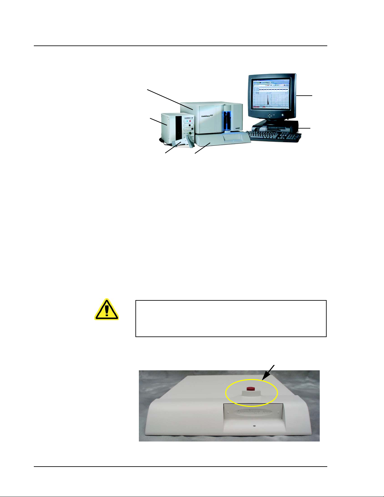
Figure 1 shows placement of the system components. The following
sections describe how to connect the Luminex 100 IS system
hardware components and install the documentation:
1. “Connect System Components” on page 2
2. “Power On PC Components” on page 5
3. “Install User Manual from CD” on page 5
PN 89-00002-00-104 Rev. A 1
Page 2
Luminex 100 IS 2.2 User Manual Installation Guide xMAP Technology
6
1
5
2
Connect System
Components
Note: The PC will be positioned
to the right of the analyzer as
Figure 1 shows. Allow sufficient
space to the left of the PC for the
analyzer.
4
1. Monitor 4. Barcode Scanner
2. PC 5. Luminex SD system (optional)
3. Luminex XYP Instrument 6. Luminex 100 Analyzer
3
Figure 1 Luminex 100 IS System Setup
To connect the system components:
1. Install the PC and monitor according to the instructions provided
by the PC manufacturer. Place the monitor on top of the PC.
2. Unpack the Luminex
instrument, the Luminex
the Luminex SD in a user manual procedure), and barcode
reader. Refer to “Hardware Components” on page 8 for a list of
system components.
Caution: Due to the weight of the analyzer, use two people for
lifting. Avoid rough handling or excessive jostling of the Luminex
100 analyzer. Do not place the PC or monitor on top of the
Luminex 100 analyzer or XYP instrument.
® 100™ analyzer, the Luminex® XYP™
® SD™ system (optional) (you connect
3. Place the Luminex XYP instrument on a clean, flat surface to the
left of the PC.
Figure 2 Remove Red Shipping Pin
2 PN 89-00002-00-104 Rev. A
Page 3

xMAP Technology Luminex 100 IS System Hardware Setup
4. Remove the red shipping pin from the XYP instrument. Leave
the silver knob in the Luminex XYP instrument. See Figure 2.
5. Place the Luminex 100 analyzer onto the Luminex XYP
instrument. See Figure 1 and Figure 3 for positioning.
6. Install the alignment guide (translucent plastic tube) by screwing
it through the opening on the Luminex analyzer into the
Luminex XYP instrument. See Figure 3. Adjust the position of
the Luminex 100 analyzer with the Luminex XYP instrument
until the alignment guide threads screw in completely.
Note: The USB cable is 5 feet
long.
Figure 3 Install Alignment Guide
7. Ensure that the power switches on the XYP instrument and
Luminex 100 analyzer are in the off position.
8. Attach the power cord to the power input module of the Luminex
XYP instrument. Attach the serial cable to the Luminex XYP
instrument. Do not plug the Luminex XYP instrument into the
power outlet.
9. Attach the power cord to the input module of the Luminex 100
analyzer. Attach the Luminex 100 analyzer USB cable
(PN 85-10011-00-046) to P1 on the Luminex 100 analyzer;
reference item 1 in Figure 4. Do not plug the power cord into the
power outlet.
10. Connect the Luminex 100 analyzer USB cable (PN 85-10011-00-
046) to a USB port on the PC; reference item 13 in Figure 4.
Connect the Luminex XYP instrument serial cable to the COM
port on the PC; reference item 15 in Figure 4.
PN 89-00002-00-104 Rev. A 3
Page 4

Luminex 100 IS 2.2 User Manual Installation Guide xMAP Technology
8
7
6
5
4
1. USB Communication Cable (P1) 9. PC
2. Luminex XYP Instrument 10. Y-Cable connection port (PS/2)
3. Luminex XYP Instrument to PC Serial Cable 11. Mouse Cable port (PS/2)
4. Power Cords 12. PC power cable
5. Luminex XYP Instrument Power Switch 13. Luminex 100 port (USB)
6. Luminex 100 Analyzer Power Switch 14. Monitor cable port
7. Luminex 100 analyzer 15. Luminex XYP port
8. Luminex SD CAN bus cable (P2) (identified for
reference)
1
3
9
2
16
15
14
16. Printer cable port
13
10
11
12
Figure 4 Luminex 100 IS Connections (Luminex 100 analyzer, Luminex XYP Instrument, and PC)
11. Connect the Y-cable to the barcode reader and keyboard, then
connect the Y-cable to the PC. See Figure 5.
Note: Device Disconnects—The
device disconnects for the
Luminex 100 analyzer, the
Luminex XYP instrument, and the
Luminex SD system are the
power cords. Do not position the
100 analyzer, XYP instrument, or
SD system such that it is difficult
operate the disconnect device
(that is remove the power supply
plugs).
12. Plug in only the PC and monitor power cords (disconnects) into
approved outlets with protective earthing only (reference user
manual). W e strongly recommend using an uninterruptible power
supply to protect the system from power variations. Refer to
“Protecting Your System” on page 6 for additional information.
4 PN 89-00002-00-104 Rev. A
Page 5

xMAP Technology Install User Manual from CD
.
4
1
3
2
1. Keyboard 3. Y-Cable
2. Barcode Reader 4. Mouse
Figure 5 Connecting the PC, Mouse, Barcode Reader, and Keyboard
Power On PC
Components
Install User Manual
from CD
Note: Adobe Reader is
automatically installed as part
of the user manual installation.
Power on the PC and monitor (power switches on front):
After you power on the PC, Microsoft
® Windows® automatically
starts up. In a moment the Luminex 100 IS software License dialog
box appears. Select Decline to exit the dialog box. Continue with the
section “Install User Manual from CD” on page 5.
To install the Luminex 100 IS user manual:
1. Insert the Luminex 100 IS User Manual CD into the drive. In a
few moments the CD autoplays and displays the installation
window. Follow the on-screen directions. If the installation
window does not appear, in the bottom left corner of the screen
select Start>Run. In the Open: box, enter D:launch and click
OK.
2. If the Luminex License dialog box appears, click Decline at this
time. If the Luminex 100 IS 2.2 software automatically starts up,
from the File menu, select Exit to close the software. See
caution.
3. After you install the desired user manual, an icon appears on the
desktop for each installed manual.
PN 89-00002-00-104 Rev. A 5
Page 6

Luminex 100 IS 2.2 User Manual Installation Guide xMAP Technology
Note: We recommend that you
begin reading the Safety ch apter
on page 2-1.
Note: You can any print any of
the manual pages from within
Adobe Reader. Select File|Print
and at the Print dialog box
select the desired parameters.
Luminex Technical
Support
4. On the desktop, double-click on the Luminex 100 IS User
Manual icon. After the Luminex 100 IS User Manual Version
2.2 opens in Adobe Reader, begin reading as desired. The
chapters are in the following order:
•“Introduction” chapter on page 1-1
• “Safety” chapter on page 2-1.
•“The System” chapter on page 3-1
•“Basic Concepts” chapter on page 4-1
•“System Calibration” chapter on page 5-1
•“Using the Luminex 100 IS 2.2 Software” chapter on page 6-1
•“Maintenance and Cleaning” chapter on page on page 7-1
•“Troubleshooting” chapter on page 8-1
•“Product Numbers” chapter on page 9-1
•“Luminex 100 IS System Installation” appendix on page A-1
•“Glossary” appendix on page B-1
•“Luminex Sheath Delivery System” appendix on page C-1
Toll free technical support is available to users in the U.S. and
Canada by calling 1-877-785-BEAD (-2323) between the hours of
7:00 a.m. and 7:00 p.m. Central T ime, Mon day through Fri day. Users
outside of the U.S. and Canada can call at +1 512-381-4397 between
the hours of 7:00 a.m. and 7:00 p.m. Central Time, Monday through
Friday. Inquiries may also be sent by email to
support@luminexcorp.com.
Users outside of the U.S. and Canada can also call Luminex B.V.
Technical Support at +31-162408333 between the hours of 8:30 a.m.
and 5:30 p.m., Monday through Friday. Inquiries may also be sent by
email to supporteurope@luminexcorp.com.
Protecting Your
System
6 PN 89-00002-00-104 Rev. A
This section provides recommendations for power protection
equipment for your system. Note that all line cords should be
plugged into outlets with protective earthing only (reference user
manual).
1.Luminex B.V. is a wholly-owned subsidiary of Luminex Corporation.
1
Page 7

xMAP Technology Luminex 100 IS System Specifications
Uninterruptible
Power Supply
(UPS)
Luminex highly recommends using an uninterruptible power supply
(UPS) to protect your system from power outages. Choose a supply
that can provide 1050 Watts for at least 45 minutes. The UPS should
be UL listed, CSA certified, and CE marked when used
internationally.
Surge Protector If you do not use a UPS, use a surge protector. Choose a protector
that meets your needs. Factors to consider include electrical
environment, endurance, suppressed voltage rating, and method of
protection. It should have six outlets, rated at least 1500 Watts, and
be UL listed, CSA certified, CE marked for nondomestic use when
used internationally .
Luminex 100 IS
System
Specifications
Luminex 100 Analyzer • Indoor use only
• Operating temperature: 15°C to 30°C (59°F to 86°F)
• Humidity: 20% to 80%, noncondensing
• Altitude: Operation up to 2400 m (7874 ft.) above mean sea level
• Physical dimensions: 43 cm (17 inches) W x 50.5 cm (20 inches)
D x 24.5 cm (9.5 inches) H
• Weight: maximum of 25 kg (60 lbs.)
• UL installation category: UL Installation Category II, as defined
in Annex J of UL 61010A-1
• Pollution degree: UL Pollution Degree 2, as defined in Section
3.7.3.2 of UL 61010A-1
• Shipping and storage: The allowable shipping and storage
temperature and humidity ranges are 0°C to + 50°C and 20-80%
noncondensing, respectively
• Input voltage range: 100 - 120 V~ ±10%, 1.4 Amp, and 200-240
V~ ±10%, 0.8 Amp, 47-63 Hz.
• AC inlet fuse: 3 Amp, 250 V~, fast acting
Luminex XYP Instrument • Ambient temperature: 15°C to 30°C (59°F to 86°F)
• Humidity: 20% to 80%, noncondensing
• Altitude: operation up to 2400 m (7874 ft) above mean sea level
• Physical dimensions: 44 cm (17.25 inches) W x 60 cm (23.5
inches) D x 8 cm (3 inches) H
PN 89-00002-00-104 Rev. A 7
Page 8

Luminex 100 IS 2.2 User Manual Installation Guide xMAP Technology
• Weight: 15 kg (33 lbs.)
• UL installation category: UL Installation Category II, as defined
in Annex J of UL 61010A-1
• Pollution degree: UL Pollution Degree 2, as defined in Section
3.7.3.2 of UL 61010A-1
• Heater operating range: 35°C to 55°C (95°F to 131°F) with
tolerance 0°C to +2°C
• Luminex XYP instrument, input voltage range: 100-240 V~
±10%, 1.8 Amps, 47-63 Hz
• AC inlet fuse: 3 A, 250 V~, fast acting
Luminex SD System • Ambient temperature: 15°C to 30°C (59° to 86°F)
• Humidity: 20% to 80%, noncondensing
• Altitude: designed to operate at up to 2400m (7874 feet) above
mean sea level
• Physical dimensions: 20 cm (8 inches) W x 30 cm (11.75 inches)
D x 24.75 cm (9.75 inches) H
• Weight: 9 kg (20 lbs)
• UL installation category: UL Installation Category II, as defined
in Annex J of UL 61010A-1
• Pollution degree: UL Pollution Degree 2, as defined in Section
3.7.3.2 of UL 61010A-1
• Input voltage range: 100-240 V~ ±10%, 0.4 Amps, 47-63 Hz
• AC inlet fuse: 2 Amp, 250 V~, time lag
PC Specifications • CE marked and UL listed
• Power cords: Power cords specific to the country of use are
included in the system as required
• Power: 115-230 V~, 6 Amps, 50-60 Hz
Hardware Components The Luminex 100 IS system includes the following hardware
components:
• Luminex 100 analyzer
• Computer (PC), monitor, and accessories
• Luminex XYP instrument
• Luminex Sheath Delivery System (Luminex SD™) (optional)
• Power cables
• Alignment guide
• One short sample probe
• Luminex XYP instrument sample probe
8 PN 89-00002-00-104 Rev. A
Page 9

xMAP Technology Luminex 100 IS System Specifications
• Reservoir
•Shield
•Heater block
• Sheath fluid container
• Waste container
• Sheath fluid line
• Air line
• Sheath fluid intake line
• Communications: 1 serial communication cable
• Communications: 1 USB communication cable
(PN 85-10011-00-046)
• Communications: 1 CAN bus communication cable
(PN 85-10011-00-068)
• Barcode reader
• Sample probe height alignment kit
• 3/32 Hexdrive, Balldriver wrench
© LUMINEX CORPORATION, 2005. All rights reserved. No part of this publication may be re produced,
transmitted, transcribed, or translated into any language or computer language, in any form or by any means
without prior express, written consent of:
LUMINEX CORPORATION Voice: (512) 219-8020 PN 89-00002-00-104 Rev A
12212 Technology Boulevard Fax: (512) 219-5195
Austin, Texas 78727-6115
U.S.A.
Luminex Corporation (“Luminex”) reserves the right to modify its products and services at any time.
This guide is subject to change without notice. Although prepared to ensure accuracy, Luminex
assumes no liability for errors or omissions, or for any damages resulting from the application or use
of this information.
The following are trademarks of Luminex Corporation: Luminex, Luminex 100, Luminex 100 IS,
LabMAP, LumAvidin, Spectral Address, Luminex HTS, Luminex SD, Luminex XYP, xMAP, Luminex
FlexMAP, and Luminex SeroMAP. All other trademarks, including Windows, Cheminert, Tween,
Pentium, and Dell.
PN 89-00002-00-104 Rev. A 9
Page 10

Luminex 100 IS 2.2 User Manual Installation Guide xMAP Technology
Installation Drawing
)
.
g
k
6
4
.
0
4
2
0
(
1
.
x
b
l
e
n
2
i
9
.
m
3
u
5
L
)
.
g
k
9
8
D
.
8
S
(
.
x
b
l
e
n
i
5
5
m
.
u
9
L
1
f
l
e
h
s
e
h
:
t
s
-
t
f
f
n
o
e
,
n
C
o
p
P
f
l
m
e
o
h
c
s
r
-
o
e
j
h
a
t
-
m
f
f
5
o
f
,
o
D
s
S
t
s
x
i
e
s
n
n
i
o
m
c
u
L
m
,
e
t
P
s
Y
y
X
S
x
S
I
e
n
0
i
0
m
1
u
x
L
e
,
n
0
i
0
m
1
u
x
L
:
e
e
s
n
i
e
h
t
m
T
o
u
.
N
L
1
r
o
f
e
c
n
d
a
e
r
t
t
a
i
e
l
m
c
o
n
e
e
b
e
v
a
h
r
e
d
a
e
r
e
d
o
c
r
a
b
d
.
n
y
t
i
a
r
a
C
l
c
P
r
e
o
h
f
T
g
.
n
r
i
e
w
d
a
a
r
e
d
r
s
i
e
h
d
t
o
c
m
r
o
a
r
f
b
)
e
.
l
g
b
k
a
c
7
6
d
.
n
6
a
7
(
,
t
.
s
b
l
u
a
7
h
6
.
x
8
e
/
6
e
1
k
:
t
a
t
h
n
i
g
i
e
d
n
w
a
.
m
g
s
e
n
t
s
i
l
s
e
o
y
c
o
s
c
c
a
p
r
o
h
o
t
f
c
r
t
i
e
e
t
w
c
n
s
n
u
r
a
o
r
e
c
a
l
w
e
l
a
o
t
p
C
o
T
.
2
3
y
l
n
o
g
n
i
h
t
r
a
e
e
.
v
i
)
t
.
c
g
e
k
t
o
1
r
.
p
1
2
h
(
t
i
.
w
b
l
s
t
5
.
e
)
4
l
.
.
t
g
6
u
k
4
o
8
n
o
t
7
w
.
n
i
o
7
h
9
d
(
s
e
.
t
g
b
o
l
g
n
u
2
l
,
r
o
o
l
f
n
o
x
o
b
d
i
u
l
f
h
t
a
e
h
s
(
.
1
p
)
.
l
5
e
a
1
b
u
2
n
d
l
t
a
u
h
m
o
g
i
r
h
e
s
e
w
s
s
u
d
m
r
e
e
o
t
c
c
y
n
s
e
e
r
l
n
i
e
a
f
t
L
e
o
.
r
T
4
(
)
2
m
m
°
°
5
0
.
.
-
+
°
0
°
°
5
0
.
.
-
+
°
0
.
s
n
o
i
t
a
l
l
a
t
s
n
i
d
n
a
g
n
i
g
a
k
c
a
p
n
o
s
n
o
i
t
c
u
r
t
s
n
i
g
n
i
l
d
n
a
h
d
n
a
g
n
i
p
p
i
h
s
w
o
l
l
o
F
.
5
d
r
e
o
h
t
c
e
r
r
.
)
t
f
i
l
o
t
e
l
p
o
e
p
2
s
e
r
i
u
q
e
r
0
0
1
X
L
(
l
a
u
n
a
m
r
e
s
u
d
e
i
l
p
p
u
s
f
o
s
n
o
i
t
c
u
r
t
s
n
i
h
o
t
e
f
e
w
s
t
t
o
a
c
p
r
e
e
e
n
p
h
n
t
o
o
e
o
c
t
r
s
i
t
a
l
d
u
D
c
e
i
S
f
c
i
f
i
x
v
d
e
e
n
s
i
i
D
t
.
i
m
s
t
u
s
a
L
e
h
c
t
e
c
h
h
t
a
c
d
e
u
n
c
s
a
n
s
,
a
e
n
P
c
i
e
Y
t
v
X
n
e
i
d
x
a
e
e
m
n
s
i
e
e
m
s
h
t
u
u
f
L
n
,
,
o
h
i
0
t
c
i
0
t
i
s
1
o
w
x
p
s
e
t
r
n
o
e
i
n
w
m
o
o
u
L
D
P
6
e
l
b
a
b
o
r
p
e
c
n
a
r
.
a
e
e
l
.
c
i
c
e
v
c
n
e
n
o
d
i
a
r
s
t
a
c
n
e
e
e
l
t
n
c
x
n
e
e
o
l
c
y
b
s
a
a
i
r
d
C
T
7
8
g
n
i
t
r
o
p
p
u
S
e
t
.
s
s
a
u
w
n
i
m
m
r
o
r
e
f
t
t
e
s
n
u
i
l
a
h
e
t
x
s
e
t
a
l
s
w
o
u
s
r
a
o
o
h
r
r
x
e
e
e
a
t
l
l
i
f
e
o
l
s
p
b
o
a
a
r
c
b
e
o
a
e
r
l
t
t
P
o
.
b
9
)
e
.
c
g
a
k
f
r
8
u
4
S
P
.
0
Y
1
X
(
.
x
b
e
l
n
i
5
0
m
.
u
2
L
3
w
e
i
V
c
i
r
t
e
m
o
s
I
)
t
s
n
c
i
i
t
o
s
P
o
t
n
s
g
e
u
a
b
i
a
o
D
h
r
x
P
E
d
t
n
r
l
a
o
o
h
s
n
S
o
o
r
i
t
g
e
a
n
l
A
i
l
s
a
e
t
l
U
s
b
n
a
I
n
b
e
r
o
o
h
r
F
P
(
W
e
c
a
f
r
u
S
g
n
i
t
r
o
p
p
u
S
0
5
.
7
t
l
e
l
s
g
o
b
u
n
i
s
i
l
r
a
s
i
o
o
r
h
s
A
x
o
e
o
E
A
C
P
0
~
4
.
0
2
0
.
5
6
1
(
)
m
m
0
.
8
.
2
0
5
(
x
e
n
i
m
u
L
)
m
m
0
8
.
.
2
0
5
(
)
m
m
0
5
.
0
9
1
(
t
s
u
a
h
x
E
8
e
y
c
a
n
r
a
T
r
a
P
e
l
Y
X
C
e
c
n
a
r
a
e
l
C
w
e
i
V
e
d
i
S
t
h
g
i
R
e
k
a
t
n
I
r
i
A
g
n
i
l
o
o
C
t
s
g
u
n
i
r
l
a
i
o
h
A
x
o
E
C
7
6
)
)
m
m
m
m
6
.
2
0
0
.
.
.
1
6
4
3
0
7
1
(
(
g
e
n
r
i
k
i
l
a
o
A
t
o
n
I
C
t
g
n
i
r
l
i
o
A
o
C
g
n
i
l
o
o
6
C
t
e
l
l
s
s
o
b
u
u
i
s
a
a
s
o
h
s
h
r
x
x
o
e
E
E
P
A
w
e
i
V
e
k
r
k
i
a
c
A
t
n
a
I
B
10 PN 89-00002-00-104 Rev. A
 Loading...