

Page 1
Luminex 100E
™
User Manual
Page 2

© LUMINEX® CORPORATION, 2004. All rights reserved. No part of this publication may be r eproduced,
transmitted, transcribed, or translated into any language or computer language, in any form or by any means
without prior express, written consent of:
LUMINEX CORPORATION
12212 Technology Boulevard
Austin, Texas 78727-6115
U.S.A.
V oice: (512) 219-8020
Fax: (512) 219-5195
Luminex 100ETM User Manual
CN-M028-01
PN 89-00002-00-013 Rev. D
July 2004
Luminex Corporation (Luminex) reserves the right to modify its product s and services at any time. This guide
is subject to change without notice. Although prepared to ensure accuracy, Luminex assumes no liability for
errors or omissions, or for any damages resulting from the application or use of this information.
The following are trademarks of Luminex: Luminex, Luminex HTS, Luminex 100, Luminex 100 IS, LabMAP,
xMAP, LumAvidin, Luminex SD, Luminex XYP, Luminex FlexMAP. All other trademarks, including Windows,
Cheminert, Pentium, and Dell
The contents of this manual and the associated Luminex software are the proper ty of L uminex and are
copyrighted. Except as specified in the End User License Agreement, any reproduction in whole or in part is
strictly prohibited.
are trademarks of their respective companies.
Page 3

Contents
Introduction 1-1
Safety 2-1
Instrument Components 3-1
About This Manual . . . . . . . . . . . . . . . . . . . . . . . . . . . . . . . . . . . . .1-1
Intended Use . . . . . . . . . . . . . . . . . . . . . . . . . . . . . . . . . . . . . . . . . .1-1
Customer Support . . . . . . . . . . . . . . . . . . . . . . . . . . . . . . . . . . . . . .1-2
Symbols. . . . . . . . . . . . . . . . . . . . . . . . . . . . . . . . . . . . . . . . . . . . . .2-1
Safety Precautions. . . . . . . . . . . . . . . . . . . . . . . . . . . . . . . . . . . . . .2-1
Laser, Luminex 100E . . . . . . . . . . . . . . . . . . . . . . . . . . . . . . . .2-2
Mechanical . . . . . . . . . . . . . . . . . . . . . . . . . . . . . . . . . . . . . . . .2-4
Biological . . . . . . . . . . . . . . . . . . . . . . . . . . . . . . . . . . . . . . . . .2-4
Decontamination of the Luminex 100E for Return Shipment . . . .2-6
Theory of Operation . . . . . . . . . . . . . . . . . . . . . . . . . . . . . . . . . . . .3-1
Hardware. . . . . . . . . . . . . . . . . . . . . . . . . . . . . . . . . . . . . . . . . . . . .3-2
xMAP Reagents. . . . . . . . . . . . . . . . . . . . . . . . . . . . . . . . . . . . . . . .3-2
Laboratory Reagents Required . . . . . . . . . . . . . . . . . . . . . . . . . . . .3 -2
Other Reagents . . . . . . . . . . . . . . . . . . . . . . . . . . . . . . . . . . . . . . . .3-2
Luminex Real-time (LXR) Library. . . . . . . . . . . . . . . . . . . . . . . . .3-3
Sensitivity . . . . . . . . . . . . . . . . . . . . . . . . . . . . . . . . . . . . . . . . .3-3
Capacity . . . . . . . . . . . . . . . . . . . . . . . . . . . . . . . . . . . . . . . . . .3-3
General, Luminex 100E . . . . . . . . . . . . . . . . . . . . . . . . . . . . . . . . .3-4
Optics . . . . . . . . . . . . . . . . . . . . . . . . . . . . . . . . . . . . . . . . . . . .3-4
Fluidics . . . . . . . . . . . . . . . . . . . . . . . . . . . . . . . . . . . . . . . . . . .3-5
Electronics . . . . . . . . . . . . . . . . . . . . . . . . . . . . . . . . . . . . . . . .3-5
System Overview . . . . . . . . . . . . . . . . . . . . . . . . . . . . . . . . . . . . . .3-5
User-Accessible Components. . . . . . . . . . . . . . . . . . . . . . . . . .3-5
Power Input Connector. . . . . . . . . . . . . . . . . . . . . . . . . . . .3-5
P1 Communications Port (DB9-PIN). . . . . . . . . . . . . . . . .3-7
P2 Synchronization Port (DB15-PIN) . . . . . . . . . . . . . . . .3-8
Air Filter. . . . . . . . . . . . . . . . . . . . . . . . . . . . . . . . . . . . . .3-10
Fluidics . . . . . . . . . . . . . . . . . . . . . . . . . . . . . . . . . . . . . . . . . .3-10
Regulated Flow Sheath Supply . . . . . . . . . . . . . . . . . . . .3-10
Sample Input Tube. . . . . . . . . . . . . . . . . . . . . . . . . . . . . .3-11
Optical. . . . . . . . . . . . . . . . . . . . . . . . . . . . . . . . . . . . . . . . . . .3-11
Installing the Luminex 100E into the Host System. . . . . . . . . . . .3-12
PN 89-00002-00-013 Rev. D i
Page 4

Luminex® 100E™ User Manual Version 1.0 xMAP Technology
Maintenance and Cleaning 4-1
Overview . . . . . . . . . . . . . . . . . . . . . . . . . . . . . . . . . . . . . . . . . . . . 4-1
Daily. . . . . . . . . . . . . . . . . . . . . . . . . . . . . . . . . . . . . . . . . . . . . . . . 4-1
Before Running Samples . . . . . . . . . . . . . . . . . . . . . . . . . . . . . 4-2
After Running Samples . . . . . . . . . . . . . . . . . . . . . . . . . . . . . . 4-2
Monthly . . . . . . . . . . . . . . . . . . . . . . . . . . . . . . . . . . . . . . . . . . . . . 4-2
Instrument Calibration. . . . . . . . . . . . . . . . . . . . . . . . . . . . . . . 4-2
Calibrate the Instrument . . . . . . . . . . . . . . . . . . . . . . . . . . 4-2
Semi-Annually . . . . . . . . . . . . . . . . . . . . . . . . . . . . . . . . . . . . . . . . 4-3
Remove or Replace the Syringe Seal. . . . . . . . . . . . . . . . . . . . 4-3
As Required . . . . . . . . . . . . . . . . . . . . . . . . . . . . . . . . . . . . . . . . . . 4-4
Instrument Front Panel. . . . . . . . . . . . . . . . . . . . . . . . . . . . . . . 4-4
Remove the Instrument Front Panel . . . . . . . . . . . . . . . . . 4-4
Reinstall the Instrument Front Panel. . . . . . . . . . . . . . . . . 4-4
Air Filter. . . . . . . . . . . . . . . . . . . . . . . . . . . . . . . . . . . . . . . . . . 4-4
Remove the Air Filter . . . . . . . . . . . . . . . . . . . . . . . . . . . . 4-4
Clean the Air Filter . . . . . . . . . . . . . . . . . . . . . . . . . . . . . . 4-4
Reinstall the Air Filter. . . . . . . . . . . . . . . . . . . . . . . . . . . . 4-5
Syringe. . . . . . . . . . . . . . . . . . . . . . . . . . . . . . . . . . . . . . . . . . . 4-5
Remove the Syringe . . . . . . . . . . . . . . . . . . . . . . . . . . . . . 4-5
Replace the Syringe. . . . . . . . . . . . . . . . . . . . . . . . . . . . . . 4-6
Verify Syringe Operation . . . . . . . . . . . . . . . . . . . . . . . . . 4-6
Product Numbers 5-1
Hardware . . . . . . . . . . . . . . . . . . . . . . . . . . . . . . . . . . . . . . . . . . . . 5-1
xMAP Reagents . . . . . . . . . . . . . . . . . . . . . . . . . . . . . . . . . . . . . . . 5-1
Index Index-1
ii PN 89-00002-00-013 Rev. D
Page 5

Introduction
1
About This Manual This manual introduces you to the Luminex
explains the features of the Luminex 100E analyzer and provides
instructions on installation and use of the analyzer.
®
100E™ analyzer. It
Intended Use The Luminex 100E analyzer is designed as a component in a host
system. This component is designed for a wide range of laboratory
testing applications measuring biomolecular reactions on the surfaces
of xMAP
indoor use only.
Systems analysts, software designers, and programmers who need an
overall perspective of the capabilities and functions of the Luminex
Runtime (LXR) should refer to the LXR Programmer’s Reference
provided by the LXR Software Development Kit (LXR SDK)
version 2.0 or greater for more information. The Luminex 100E
analyzer responds to applications developed using the LXR SDK
version 2.0. LXR SDK version 2.0 supplies the runtime software and
several utility applications needed to develop new applications and
maintain the Luminex 100E analyzer.
®
and customer-specific microspheres. It is intended for
LXR is packaged as a collection of Windows
The interfaces of the various components are written as Component
Object Model (COM) objects that conform to the Microsoft
automation standards. This COM Automation support allows access
to the Luminex 100E analyzer via programming and scripting
software.
PN 89-00002-00-013 Rev. D 1 - 1
®
binary and data files.
®
Page 6

Luminex 100E User Manual xMAP Technology
Technical Support You can contact Luminex Technical Support for questions or
concerns regarding the Luminex 100E analyzer.
Users in the U.S. and Canada may call 1-877-785-BEAD (-2323)
between the hours of 7:00 a.m. and 7:00 p.m. Central Time, Monday
through Friday for assistance. Users outside of the U.S. and Canada
can contact us at + 1 512-381-4397 between the hours of 7:00 a.m. to
7:00 p.m. Central Time, Monday through Friday.
Inquiries may also be sent by email to support@luminexcorp.com.
1 - 2 PN 89-00002-00-013 Rev. D
Page 7
Safety
2
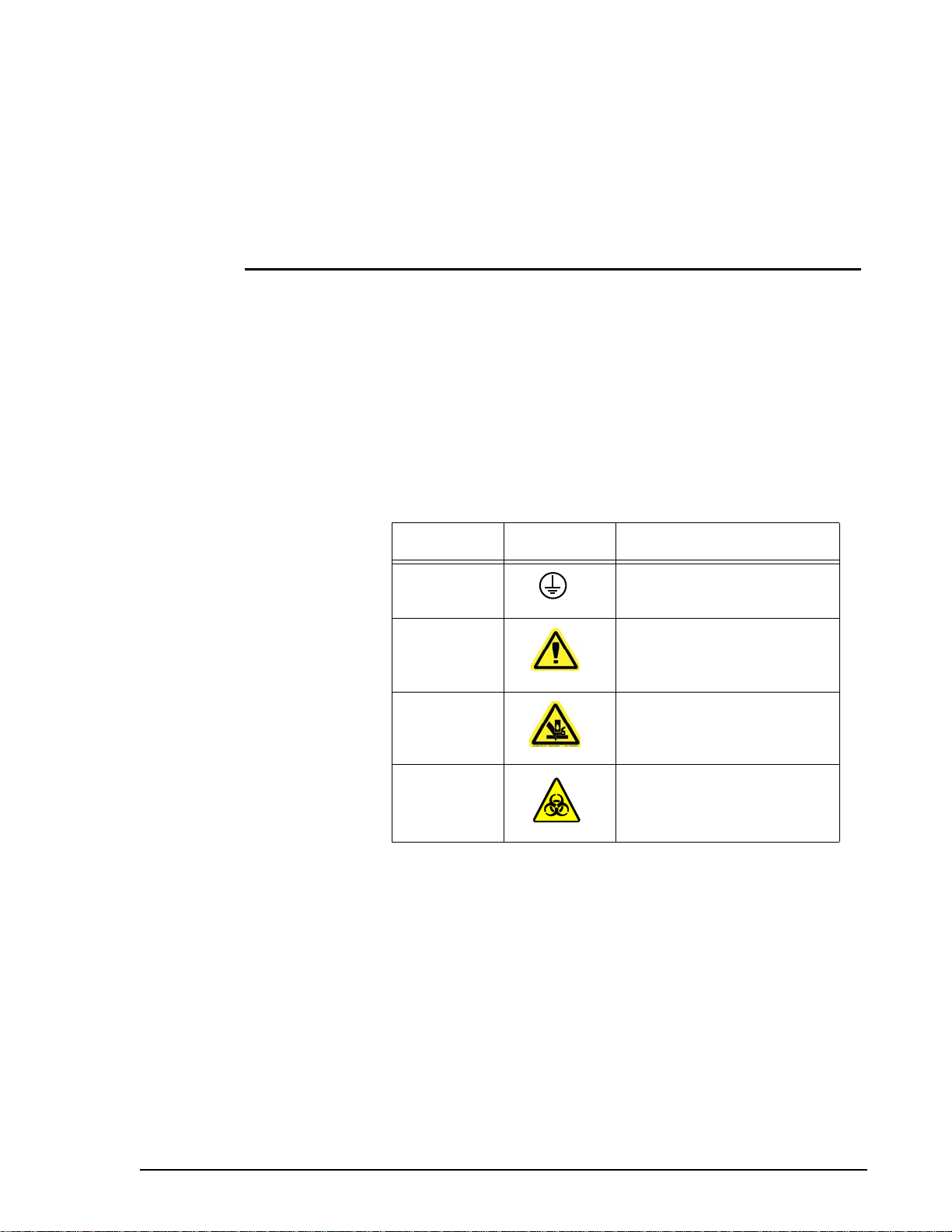
Symbols These symbols describe warnings, cautions, and general information
used in the operation of this Luminex 100E analyzer. These symbols
are further defined under “Safety Precautions.”
Number Symbol Description
1 Protective ground
2 Warning (refer to manual)
3 Warning (refer to manual)
4 Warning (refer to manual)
Safety Precautions Read the following safety information before setting up or using the
Luminex 100E analyzer. The user should be present during
operation. The Luminex 100E analyzer contains electrical,
mechanical, and laser components which, if handled improperly, are
potentially harmful. In addition, biological hazards may be present
during system operation. Therefore, we recommend that all Luminex
100E analyzer users become familiar with the specific safety
advisories below, in addition to adhering to standard laboratory
safety practices. The protection provided by the equipment may be
impaired or the warranty voided if the system is used in a manner not
specified by the instructions or Luminex Corporation.
PN 89-00002-00-013 Rev. D 2 - 1
Page 8
Luminex 100E User Manual xMAP Technology
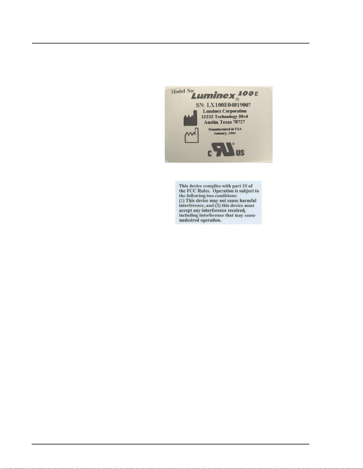
The following labels appear on the back panel of the Luminex 100E
analyzer.
Figure 1. Voltage Label
Figure 2. FCC Label
Note: This equipment has been tested and found to comply with the
limits for a Class B digital device, pursuant to part 15 of the FCC
Rules. These limits are designed to provide reasonable protection
against harmful interference in a residential installation. This
equipment generates, uses and can radiate radio frequency energy
and, if not installed and used in accordance with the instructions,
may cause harmful interference to radio communications. However,
there is no guarantee that interference will not occur in a particular
installation. If this equipment does cause harmful interference to
radio or television reception, which can be determined by turning the
equipment off and on, the user is encouraged to try to correct the
interference by one or more of the following measures:
• Reorient or relocate the receiving antenna.
• Increase the separation between the equipment and the
receiver.
• Connect the equipment into an outlet on a circuit different
from that to which the receiver is connected.
• Consult the dealer or an experienced radio/TV technician for
help.
2 - 2 PN 89-00002-00-013 Rev. D
Page 9

xMAP Technology Safety
Do not perform any maintenance or cleaning of the electrical
.
components of this system.
The Luminex 100E analyzer complies with European Union (EU)
safety requirements.
This analyzer contains fluidic components. In the event of a fluidic
leak, disconnect the power. Contact Luminex Corporation for further
information.
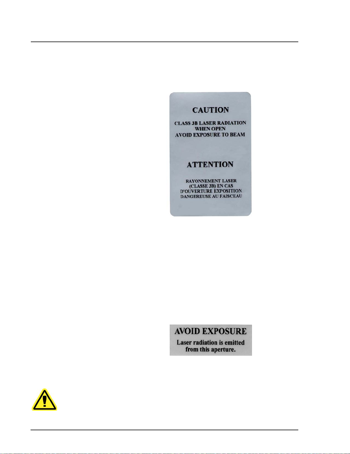
Laser, Luminex 100E United States and international regulations require the following
warnings to appear on the analyzer during operation and
maintenance. The labels in this section are representative.
Figure 3. Laser Class Label
The following label appears on the back panel of the Luminex 100E
analyzer.
Figure 4. Laser Caution Label
Under NO circumstances should you remove the Luminex 100E
analyzer cover or this label! When performing routine
maintenance, disconnect power to the analyzer.
PN 89-00002-00-013 Rev. D 2 - 3
Page 10
Luminex 100E User Manual xMAP Technology
All Luminex 100E analyzer laser apertures are contained inside a
protective housing within the analyzer. This label appears on the
optics cover within the Luminex 100E analyzer.
Mechanical
Figure 5. Laser Caution Label on Optics Cover
CAUTION — Use of controls or adjustments or performance of
procedures other than those specified herein may result in hazardous
radiation exposure.
Attention — L’utilisation des commandes ou réglages ou l’exéction
des procédures autres que celles spécifiées dans les présentes
prescriptions peuvent être cause d’une exposition à un rayonnement
dangereux.
This label appears above the laser apertures located inside the optics
enclosure inside the Luminex 100E analyzer.
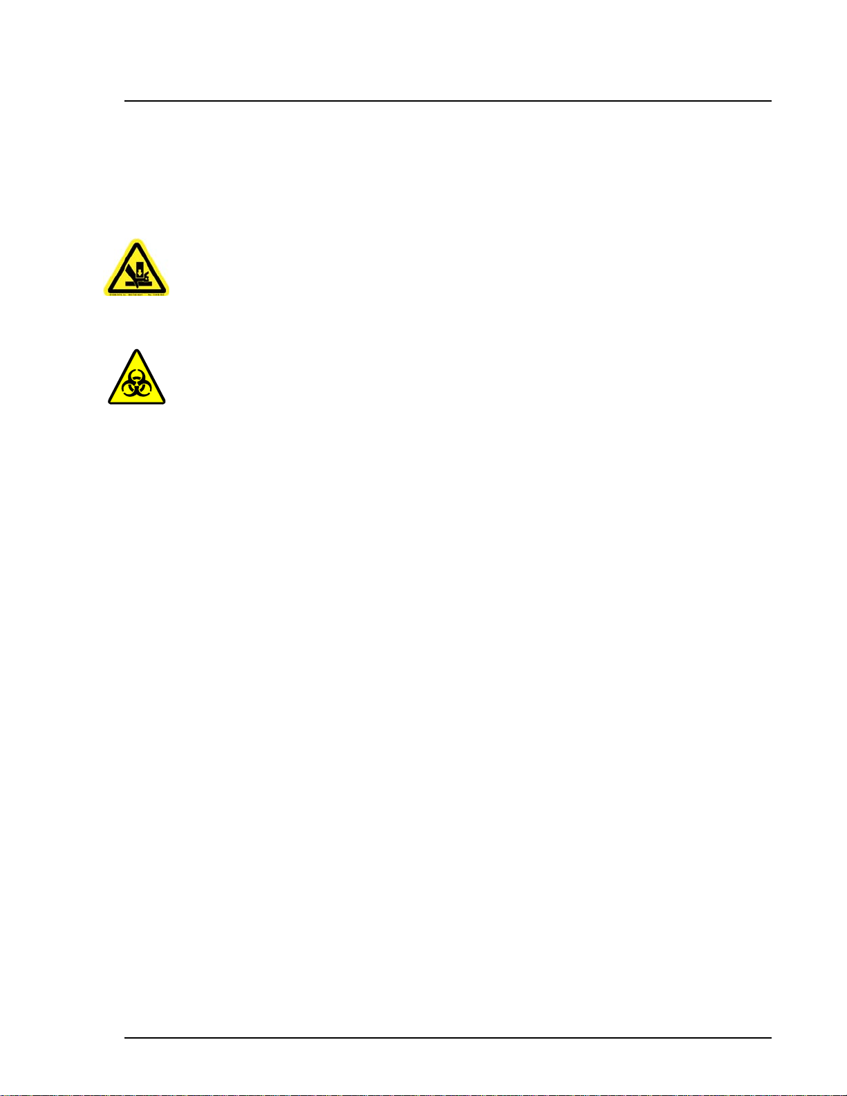
Figure 6. Avoid Exposure Label
Warning: During operation, this analyzer contains moving parts.
Risk of personal injury is present. Observe all warnings and cautions.
2 - 4 PN 89-00002-00-013 Rev. D
Page 11
xMAP Technology Safety
Warning: During operation, this analyzer contains moving parts that
result in a pinch point hazard. Risk of personal injury is present.
Keep hands and fingers away from the syringe arm.
Biological Warning: All human/animal samples may contain hazardous
infection agents.Where exposure (including aerosol) to potentially
biohazardous materials exists, operators should follow appropriate
biosafety procedures and use personal protective equipment, such as
gloves, gowns, laboratory coats, face shields (or mask and eye
protections), and ventilation devices.
Observe all local, state, and federal biohazard handling regulations
when disposing of biohazardous waste material.
PN 89-00002-00-013 Rev. D 2 - 5
Page 12

Luminex 100E User Manual xMAP Technology
Decontaminating
the Luminex 100E
Analyzer for Return
Shipment
Note: You are responsible for
decontaminating the unit prior
to shipment.
Luminex Technical Support will provide a Return Material
Authorization (RMA) number if they direct you to return the
analyzer to Luminex; they will also instruct you in returning the
analyzer according to Luminex procedures.
Before returning the Luminex 100E analyzer, sanitize and
decontaminate the accessible surfaces and internal fluidics system.
This is particularly important if you have analyzed biohazardous
samples. Make a copy of this page to complete and return with the
analyzer. Submit the completed checklist, both signed and dated,
with the Luminex 100E analyzer.
1. Replace the fluid in the sheath system with a freshly prepared
solution of 10% - 20% household bleach and water.
2. Using a solution of 10% - 20% household bleach and water,
sanitize the analyzer using maintenance tools in the LXR library.
Follow this by washing twice with distilled water.
3. Disconnect the power plug from the analyzer
4. Disconnect the fluidic lines.
5. Disconnect the sample probe from the host’s sample mount
sample probe line.
6. Wash all exterior surfaces with a mild detergent, followed by a
10%-20% bleach solution.
7. Remove the air filter from the analyzer and clean all accessible
surfaces with detergent followed by a 10%-20% bleach solution.
8. Pack the analyzer using a biohazard bag, place it in an approved
shipment box, and then insert it into a shipping crate. Attach this
checklist to the top of the corrugated box prior to packaging in
the crate.
Was there an internal leak in the system? Yes No
Print Name:___________________________ ____ _____ ____
Signature:__________________________________________
Date:______________________________________________
2 - 6 PN 89-00002-00-013 Rev. D
Page 13

Luminex 100E Analyzer Overview
3
Theory of Operation The Luminex 100E analyzer was specifically designed to be a
component of a host system.
Luminex 100E analyzer technology is based on flow cell fluorometry
with Luminex-developed innovations. The fluidics and optics work
together to enable simultaneous analysis of up to 25 analytes in a
single test sample using the Luminex 25 beadmap.
There are two fluidics paths in the Luminex 100E analyzer. The first
path involves a syringe-driven mechanism that draws the sample into
the Luminex 100E analyzer for analysis. The host system drives the
second fluidics path at a controlled rate to supply sheath fluid to the
cuvette. The Luminex analyzer’s syringe-driven system transports a
specified volume of sample from a sample container to the cuvette.
The sample is injected into the cuvette at a steady rate for analysis.
Following analysis, the sample path is automatically purged with
sheath buffer by the second fluidics path. This process removes
residual sample within the tubing, valves, and probe.
Sheath fluid is the delivery medium of the sample to the optics
component. The analysis sample is acquired using the host system’s
sample aspiration interface and is injected into the base of the
cuvette. The sample passes through with sheath fluid at a controlled
rate in a narrow sample core to ensure that each microsphere is
illuminated individually. The sample injection rate is such that the
microspheres are introduced to the optics path as a series of single
events.
The optics assembly consists of two lasers. One laser excites the dye
mixture inside the microspheres, and the second laser excites the dye
bound to the surface of the microspheres. Avalanche photo
PN 89-00002-00-013 Rev. D 3 - 1
Page 14

Luminex 100E User Manual xMAP Technology
diode (APD) detectors measure the excitation emission intensities of
the color coding classification dye mixtures inside the microspheres
and a photomultiplier tube detects the excitation emission intensity
of the reporter dye bound to the surface of the microspheres. High
speed digital signal processors (DSP) and advanced computer
algorithms provide analysis of the microspheres as they are
processed through the Luminex 100E analyzer.
Hardware The Luminex 100E analyzer consists of these major components:
• Analog PCBA
• Digital PCBA
• Sensor distribution PCBA
• Laser driver PCBA
• Optics assembly
• Syringe pump
• Pressure sensor
• Backflush valve
• Sample valve
• Air filter
xMAP Reagents • Classification calibration microspheres (CAL1)
• Reporter calibration microspheres (CAL2)
• Sheath fluid
Laboratory
Reagents Required
• Household bleach
• 70% isopropanol or 70% ethanol
• Mild detergent
• Distilled water
Other Reagents • Customer-specified reagents
3 - 2 PN 89-00002-00-013 Rev. D
Page 15

xMAP Technology Luminex 100E Analyzer Overview
Luminex Runtime
(LXR)
Luminex Runtime (LXR) version 2.0 is a set of software components
that provides simple, standardized mechanisms for programmable
control of the Luminex 100E analyzer .
Use the LXR Software Development Kit (SDK) version 2.0 or
greater to write your own programs that analyze the results from the
Luminex 100E analyzer. It includes sample test programs. Online
documentation and other test programs are in the LXR Programmer’s
Reference.
LXR SDK version 2.0 allows the application developer to connect to
a Luminex 100E analyzer, collect data, access its state, and control
its operations. LXR version 2.0 performs these functions:
• controls the operations of Luminex 100E analyzers through
• processes real-time Luminex 100E analyzer data
• retrieves classified, statistical data in real time
• monitors and sets Luminex 100E analyzer status
• interacts with Luminex 100E analyzers using high-level, user-
• adds on higher-level extensions, such as monitoring, data tracing,
• performs automatic and custom activity logging
• provides maintenance diagnostic information
commands
oriented software and development tools, achieving easy, rapid
application development
standardized calibration, and user error reporting
General, Luminex
100E Analyzer
See the LXR version 2.0 Programmer’s Reference for more details.
• Installation into host < 2 hours
• System calibration < 10 minutes
• Analyze up to 100 samples per hour (dependent upon
microsphere concentration within the sample)
• Analyze up to 25 xMAP microsphere sets per sample using the
Luminex 25 beadmap.
• Luminex 100E analyzer warmup: 30 minutes. Software functions
that remain inactive for at least 4 hours (programmable default)
require a warmup to restart. Warmup is required 4 hours
(programmable default) from the time the last sample was
analyzed.
• Operating temperature: 15°C to 30°C (59°F to 86°F)
• Storage temperature: 0°C to 50°C (32°F to 122°F)
• Humidity: 20% to 80%, noncondensing
• Altitude: Operation up to 2400 m (7874 ft) above mean sea level
PN 89-00002-00-013 Rev. D 3 - 3
Page 16

Luminex 100E User Manual xMAP Technology
• Physical dimensions, excluding mounting brackets, connectors,
and tubing, are: 31.1 cm (12.25 inches) W x 50 cm (19.7 inches)
D x 29.2 cm (11.5 inches) H
• Weight: 21.8 kg (48.0 lbs.)
• Shipping and storage: The allowable shipping and storage
temperature and humidity ranges are 0°C to +50°C and up to
80% noncondensing
• Underwriters Laboratories, Inc. (UL
Installation Category II, as defined in Annex J of UL 61010A-1
• Pollution degree: UL Pollution Degree II, as defined in Section
3.7.3.2 of UL 61010A-1
• Classification of microspheres > 80%
• Misclassification of microspheres < 0.5%
• Internal sample carry over < 3%
• Soluble background fluorescence emission at 575 nm
automatically subtracted from median fluorescence intensity
(MFI) value
®
) installation category: UL
Sensitivity • Detect 1000 fluorochromes phycoerythrin (PE) per microsphere
• Reporter channel dynamic range: 3.5 decades of detection
Capacity • Sample core: 15 - 20 µm core at 1 µL/sec sample injection rate
Optics • Reporter laser: 532 nm, nominal output 15-16.5 mW , maximum
of 500 mW, frequency -doubled diode; mode of operation,
continuous wave (CW)
• Classification laser: 635 nm, 9.1 mW ± 6%, maximum output
25 mW, diode; mode of operation, continuous wave (CW)
• Reporter detector: Photomultiplier tube, detection bandwidth of
565 - 585 nm
• Classification detector: Avalanche photo diode (APD) with
temperature compensation
• Doublet discrimination detector: Avalanche photo diode (APD)
with temperature compensation
3 - 4 PN 89-00002-00-013 Rev. D
Page 17

xMAP Technology Luminex 100E Analyzer Overview
Fluidics • Sheath flow specification rate: 90 µL/second ± 5 µL/second
• Cuvette: 200 micron square flow channel
• Sample injection rate: 1 µL/second ± .05 µL variable default
• Sample uptake volume: 20 - 200 µL
• Pressure connections to the unit should not exceed 10 PSI during
normal operating conditions.
Electronics • Reporter channel detection, A/D resolution: 14 bits
• Communications interface: USB
• Classification and doublet discriminator channel detection:
Avalanche photo diode (APD) with temperature compensation,
A/D resolution: 12 bits
System Overview The Luminex 100E analyzer consists of three subsystems: electronic,
fluidic, and optical. An air filter fits under the front cover of the
analyzer. There is no user access to the optics.
User-Accessible
Components
Power Input
Connector
The following section describes the user-accessible components of
each subsystem, where applicable.
The power input connector receives power when connected to an
external source. The power input connector is shipped with a plastic
cap. Remove the cap to access the 21-pin connector. The 21-pin
cylindrical connector supplies the power for several different
components of the Luminex 100E analyzer, including the fan,
syringe pump, backflush valve, sample valve, analog board, digital
board, red laser, and green laser.
Figure 7. Power Input Connector
PN 89-00002-00-013 Rev. D 3 - 5
Page 18

Luminex 100E User Manual xMAP Technology
The power input connector type is a Amphenol JTP02RE-2221P(014), and it connects with Amphenol JT06RE-22-21S(014).
Equivalent parts can be used. The Luminex 100E analyzer operates
off of five separate dc voltage levels, including 24 volts, 15 volts, -15
volts, and 6 volts. The pinout follows below:
• +15 pins E, F
• -15 pin G
• +24 pin J
•+6 pin C
• +15 Return pins P, S
• +24 Return pin H
• +6 Return pin D
• Chassis ground pin A
• 5.4 volts pins L, M, W
• 5.4 Return pins F, K, N
• 5.4 V (+) sense pin B
• 5.4 V (-) sense pin R
• -15 volts return pin U
The user must provide power interruption and fusing means.
The power required from the host system to run the Luminex 100E
analyzer is listed below. The voltages listed are required at the dc
power connector. This power requirement allows for the use of
additional components at a later date.
Note: The 6 volt line must be at least 5.5 volts.
Note: The +15 volt supply must be at a minimum of 90% of rated
output at least 15 (±5) milliseconds before the 6 volt supply reaches
10% of rated output to ensure proper operation.
Note: The laser supply voltage (+5.4 volts) must be at a minimum of
90% of rated output no later than 15 (±5) milliseconds after the 15
volt supply is at 90% of rated output. The 5.4 volt supply must be
capable of providing a voltage of 5.3 to 5.5 volts dc at the sense
points located within the Luminex 100E analyzer. The load initially
varies between 0 and 50 W. After 15 seconds, the load decreases to
less than 40W.
3 - 6 PN 89-00002-00-013 Rev. D
Page 19

xMAP Technology Luminex 100E Analyzer Overview
P1 Communications
Port (DB9-PIN)
Supply voltage
(V)
Noise (mVpp) Maximum Current
(Amps)
+6.0 ±2% 60 1
+ 5.4 220 10
+24.0 ±2% 240 2
+15.0 ±3% 150 1
-15.0 ±3% 150 0.5
The 24 volt power supply should not be capable of delivering, under
any load condition including short circuit, 8 amps after one minute of
operation.
The 15 volt, negative 15 volt, and 6 volt, and 5.4 volt power supplies
should not be capable of delivering, under any load condition
including short circuit, 150 VA per supply after one minute of
operation.
The P1 Communications Port is a custom USB port that is the main
communications interface for two-way communication between the
Luminex 100E analyzer and the host computing and control system.
A custom DB9-to-USB cable is provided.
1
2
1. P1 9-pin Communications Port
2. P2 15-pin Synchronization Port
Figure 8. Communication Ports
PN 89-00002-00-013 Rev. D 3 - 7
Page 20

Luminex 100E User Manual xMAP Technology
The P1 Communications Port is a nine-pin DB female-style
connector for communication between the P1 port and the host
computing and control system.
Table 1 lists the P1 communications port pinouts.
Table 1: P1 Communications Port Pinout
Pin Number voltages Description
Pin 1 None USB DPin 2 Maximum of 5.25 Reserved
P2 Synchronization
Port (DB15-PIN)
Pin 3 No voltage originates from the
Luminex 100E analyzer at this
pin
Pin 4 None No connect
Pin 5 None Chassis
Pin 6 Maximum of 5.25 USB D+
Pin 7 None No connect
Pin 8 None USB ground
Pin 9 No voltage originates from the
Luminex 100E analyzer at this
pin
Reserved
ground
USB Vbus
The P2 Synchronization Port is a digital I/O port that provides one
input line and two output lines. The P2 synchronization port is used
to connect the Luminex 100E analyzer and the host computing and
control system. Refer to “P2 Synchronization Port Pinout” on
page 3-9 to see the P2 synchronization port.
The P2 Synchronization Port is a 15-pin DB female style connector
to allow communication between the Luminex 100E analyzer and the
host computing and control system.
The Luminex 100E analyzer uses open collector outputs; the inputs
are designed to interface with open collector outputs from the host
system.
3 - 8 PN 89-00002-00-013 Rev. D
Page 21

xMAP Technology Luminex 100E Analyzer Overview
Table 2 lists the P2 synchronization port pinouts.
Table 2: P2 Synchronization Port Pinout
Pin Number voltages Description
Pin 1 None Unused
Pin 2 None Input 1 return
Pin 3 Unloaded, maximum voltage of
5.25 volts
Pin 4 None Unused
Pin 5 None Output 1 return
Pin 6 No voltage originates from the
Luminex 100E analyzer at this
pin
Pin 7 None Unused
Pin 8 None Spare output
Pin 9 Unloaded, maximum voltage of
5.25 volts
Pin 10 None Unused
Pin 11 None Sp are input
Pin 12 No voltage originates from the
Luminex 100E analyzer at this
pin
Spare input
Output 2
return
Input 1
return
Output 1
Pin 13 None Unused
Pin 14 None Output 2 return
Pin 15 No voltage originates from the
Luminex 100E analyzer at this
pin
PN 89-00002-00-013 Rev. D 3 - 9
Sp are output
Page 22

Luminex 100E User Manual xMAP Technology
Air Filter The air filter is located on the front of the Luminex 100E analyzer
behind the front panel. See “Air Filter” on page 4-4 for more
information.
For proper ventilation, do not obstruct the area in front and allow at
least one inch (2.54 cm) of clearance around the Luminex 100E
analyzer.
Fluidics
Regulated Flow
Sheath Supply
Figure 9. Air Filter Inside the Front Cover of the
Luminex 100E Analyzer
Located on the side of the Luminex 100E analyzer are three
connectors that couple directly to the host system’s sheath and waste
fluid subsystems. The nonpressurized sheath fluid connector is blue,
the waste fluid connector is orange, and the pressurized sheath fluid
connector is green.
Note: The host instrument provides the means for waste disposal.
3 - 10 PN 89-00002-00-013 Rev. D
Page 23

xMAP Technology Luminex 100E Analyzer Overview
1
1. Nonpressurized Sheath Fluid Connector (Blue)
2. Waste Fluid Connector (Orange)
3. Pressurized Sheath Fluid Connector (Green)
Figure 10. Regulated Flow Sheath Supply
2
3
Sample Input Tube The sample input tube provides the sample fluid interface between
the sample probe from the host system to the Luminex 100E
analyzer. This sample input tube aspirates sample.
Figure 11. Sample Input Tube (Without Cap)
Optical The optical system consists of the optical assembly and the excitation
lasers. The optical assemblies do not require manual adjustment by
the user.
PN 89-00002-00-013 Rev. D 3 - 11
Page 24

Luminex 100E User Manual xMAP Technology
Installing the
Luminex 100E
Analyzer into the
Host System
Note: Due to the weight, use
two people to lift the Luminex
100E analyzer.
The Luminex 100E analyzer has three electrical and four fluid
connectors that interface to the host system:
• P1 Communications Port
•P2
• Power input connector
• Sample Input Tube
• Nonpressurized Sheath Fluid Connector
• Waste Fluid Connector
• Pressurized Sheath Fluid Connector
Synchronization Port
To install the Luminex 100E analyzer into the host system:
1. Connect the USB communications cable from the host system to
the P1 communications port (DB9) on the Luminex 100E
analyzer.
2. Connect the synchronization cable from the host system to the
P2 Synchronization Port (DB15) on the Luminex 100E analyzer.
3. Connect the nonpressurized sheath, waste, and pressurized
sheath fluid lines from the host system into the color-coordinated
connectors at the lower left of the sample input tube on the
Luminex 100E analyzer. The connectors snap into the injection
port using firm pressure.
4. Remove the white cap covering the sample input tube and
connect it to the sample aspiration interface from the host
system.
5. Remove the yellow cap covering the power input connector and
connect the power source from within the host system to the
power input connector (21-pin cylindrical connector) on the
Luminex 100E analyzer.
6. Place the Luminex 100E analyzer into the host system.
3 - 12 PN 89-00002-00-013 Rev. D
Page 25

xMAP Technology Luminex 100E Analyzer Overview
5
2
NOTES:
1. THE LUMINEX 100E IS A COMPONENT OF A LARGER HOST SYSTEM.
CLEARANCE FOR COOLING AND INTAKE/EXHAUST.
3. TOTAL UNIT WEIGHT: 48.0 lb. (21.7 kg.).
4. FOLLOW SHIPPING AND HANDLING INSTRUCTIONS ON PACKAGING AND INSTALLATION INSTRUCTIONS OF
SUPPLIED USER MANUAL (LX100E REQUIRES 2 PEOPLE LIFT).
CABLE CLEARANCE.
MOUNTING HOLES
9X 832UNC
3X 11.12
3X 1.12
3X 6.12
3X 3.06
3X 11.13
3X 18.02
SUPPORTING SURFACE
ISOMETRIC VIEW
01
LUMINEX 100E
48.0 lb. (21.7 kg.)
SUPPORTING SURFACE
GROUNDING
STUD
01
Figure 12. Installation Drawing
PN 89-00002-00-013 Rev. D 3 - 13
Page 26

Luminex 100E User Manual xMAP Technology
Figure 13. Installation Drawing
3 - 14 PN 89-00002-00-013 Rev. D
Page 27

Maintenance and Cleaning
y
4
Overview The Luminex 100E analyzer requires proper maintenance and
cleaning to ensure optimal performance. Read and follow all
instructions in this section.
The following list is a basic timeline for performing maintenance and
Warning: When analyzing
potentially infectious
biological samples on the
analyzer, follow standard
laboratory safety practices.
These safety precautions
should also be taken when
cleaning or maintaining the
analyzer.
Warning: Do not remove
the analyzer cover under an
circumstances!
cleaning procedures:
• Daily
– Before running samples
– After running samples
• Monthly
– Luminex 100E analyzer calibration
calibrate the analyzer
• Semi-annually
– Remove or replace the syringe seal
• As required
– Luminex 100E analyzer front panel
Remove the front panel
Reinstall the front panel
– Air filter
Remove the air filter
Clean the air filter
Reinstall the air filter
– Syringe
Remove the syringe
Replace the syringe
Verify syringe operation
PN 89-00002-00-013 Rev. D 4 - 1
Page 28

Luminex 100E User Manual xMAP Technology
Daily Note: If the Luminex 100E analyzer is powered on, but idle for more
than four hours, you must rewarm the optics. The Luminex 100E
analyzer and optics system take approximately 30 minutes to warm
up.
Before Running Samples Before running samples:
1. Perform a Sanitize command with 70% isopropanol or 70%
ethanol.
2. Perform two Wash commands with sheath fluid.
After Running Samples Perform a Sanitize command with 10%-20% household bleach
solution. If powering off the Luminex 100E analyzer, perform two
Wash commands with distilled water.
Monthly
Luminex 100E Analyzer
Calibration
Calibrate upon installing the Luminex 100E analyzer, at least once a
month, during routine use, and when:
• the system is moved
• a part is replaced
• the delta calibration temperature is more than three degrees
Calibrate the Luminex 100E analyzer to normalize settings for the
reporter channel, both classification channels, and the doublet
discriminator channel. See the calibration section from the host
system’s software manual for further information.
4 - 2 PN 89-00002-00-013 Rev. D
Page 29

xMAP Technology Maintenance and Cleaning
Semi-Annually
Remove or Replace the
Syringe Seal
Warning:
OFF and unplug the power
cord before replacing the
syringe plunger seal! The
syringe arm does not
deactivate when changing the
plunger; injury could result if
the analyzer is not
unplugged.
Turn the unit
Remove or replace the syringe plunger seal for optimal performance
in the Luminex 100E analyzer.
To access the syringe, you must first remove the Luminex 100E
analyzer front panel and air filter. See “Reinstall the Luminex 100E
Analyzer Front Panel” on page 4-4 for more information.
To remove or replace the syringe seal:
1. Turn the Luminex 100E analyzer off and unplug the power cord
before replacing the syringe plunger.
2. Replace the syringe plunger seal every six months. See the
warning to the left of this paragraph.
3. Remove the front panel from the front of the Luminex 100E
analyzer.
4. Locate the syringe (a glass cylinder with a metal rod).
5. Unscrew the knob on the syringe arm (at the bottom of the
syringe), and forcefully push the syringe arm down.
6. Unscrew the syringe from the top of its housing, and then pull
the plunger out of the syringe.
7. Remove and replace the plunger seal, and return the plunger to
the syringe.
8. Screw the syringe back into the top of its housing.
9. Return the syringe arm to its original position.
10. Hand-tighten the screw on the syringe arm.
11. Plug in the power cord and turn the Luminex 100E analyzer on.
12. Prime the Luminex 100E analyzer five times. Be sure to watch
for any leaks in the syringe area.
13. Replace the Luminex 100E analyzer front panel.
PN 89-00002-00-013 Rev. D 4 - 3
Page 30

Luminex 100E User Manual xMAP Technology
As Required
Luminex 100E Analyzer
Front Panel
Remove the Luminex
To access many of the analyzer’s components for periodic
maintenance, you must first remove the front panel. Additionally,
you may need to remove the air filter located behind the analyzer’s
front panel.
To remove the Luminex 100E analyzer front panel:
100E Analyzer Front
Panel
Reinstall the Luminex
1. Remove the six button-head screws and washers.
2. Lift out the Luminex 100E analyzer front panel.
To reinstall the Luminex 100E analyzer front panel:
100E Analyzer Front
Panel
1. Install the front panel with louvers facing down and out, and
align it with the six screw holes.
2. Install the six washers and button-head screws.
Air Filter Remove and replace the air filter as necessary.
Periodically , you may need to clea n the air filter for optimal Luminex
100E analyzer performance. To clean the air filter, you must first
remove it from the Luminex 100E analyzer. Do not run samples
when the air filter is not in place. Clean the air filter as necessary.
Remove the Air Filter To remove the air filter:
1. Remove the front panel from the Luminex 100E analyzer.
2. Remove the two spring clamp flaps from each side of the filter
and lift out the air filter.
Clean the Air Filter To clean the air filter:
1. Remove the air filter.
2. Clean the filter with a vacuum or by placing it under running
distilled water.
3. Stand the air filter up to air dry.
4. Reinstall the air filter.
4 - 4 PN 89-00002-00-013 Rev. D
Page 31

xMAP Technology Maintenance and Cleaning
Reinstall the Air Filter To reinstall the air filter:
1. Install the air filter and lift into position and place the two spring
clamp flaps.
2. Reinstall the Luminex 100E analyzer front panel.
Syringe Remove and replace the syringe every six months.
Remove the Syringe When removing the syringe and the air filter, you must remove the
front panel of the Luminex 100E analyzer. See “Luminex 100E
Analyzer Front Panel” on page 4-4 for more details.
To remove and replace the syring e:
1. Perform the decontamination procedure. See “Decontaminating
the Luminex 100E Analyzer for Return Shipment” on page 2-6
for details.
2. Turn off the Luminex 100E analyzer, but make sure the Luminex
100E analyzer is connected to protective ground. Wear a ground
strap.
3. Remove the front panel from the Luminex 100E analyzer. See
“Luminex 100E Analyzer Front Panel” on page 4-4 for more
information.
4. Remove the air filter.
5. Loosen the thumb screw on the bottom of the syringe arm.
6. Lower the syringe arm completely.
7. Unscrew the syringe from the pump head.
8. Remove the syringe.
Replace the Syringe To replace the syringe:
Note: Ensure that the Luminex 100E analyzer is powered off prior to
replacing the syringe.
1. Screw the new syringe into the syringe head.
2. Lift the syringe arm up to the bottom of the syringe.
3. Tighten the thumb screw.
PN 89-00002-00-013 Rev. D 4 - 5
Page 32

Luminex 100E User Manual xMAP Technology
4. Install the air filter.
5. Verify that the syringe works properly. See “Verify Syringe
Operation” for details below.
6. Reinstall the Luminex 100E analyzer front panel.
Verify Syringe
Operation
When you replace the syringe, you must verify that it runs properly.
If the syringe works improperly, it may not move freely or it may
leak. Leaks may occur where the metal threaded housing screws into
the syringe valve or at the bottom of the syringe.
To verify syringe operation:
1. Turn the analyzer on.
2. Run a Prime command using LXR and observe the syringe
(found behind the front panel). See if the syringe moves freely or
if there are leaks around the syringe. If the syringe does not
move freely, contact Technical Support. If the syringe leaks,
determine from where it leaks.
If it leaks at the top of the syringe where the metal threaded
housing screws into the syringe valve, order a new syringe.
If it leaks at the bottom of the syringe cylinder, you must replace
the syringe seal. A good indicator of a leak in the syringe
cylinder is if you see saline crystals forming at the bottom of the
syringe over time.
3. When the prime completes, see if the syringe leaks sheath fluid
beneath the analyzer.
4. Repeat steps 2-4 until you complete five primes. If the syringe
moves freely and no leaks or puddles appear around the syringe,
the syringe works correctly.
5. Calibrate the analyzer to normalize settings for the analyzer
reporter channel, both classification channels, and the doublet
discriminator channel.
Use xMAP control microspheres with the analyzer to verify that
calibration and optical integrity for the system exist.
4 - 6 PN 89-00002-00-013 Rev. D
Page 33

5
Hardware
Product Numbers
Note: These part numbers are subject to change without notification.
Assy, Weldment, Short Sample Sleeve
with Filter [Short Sample Probe]
CN-0006-01
xMAP Reagents
Filter, Air, Front Mount 7.5 x 10.63 [Air
filter behind Luminex 100E front cover]
Cable, USB CN-0018-01
Manual, Luminex 100E User Manual CN-M028-01
Syringe Cylinder with Seal CN-0013-01
Syringe Seal [Set of 4] CN-0014-01
Microspheres, LX100, CL1 CL2 Calibration [xMAP Classification Calibration Microspheres]
Microspheres, LX100, RP1 Calibration
[xMAP Reporter Calibration Microspheres]
Sheath Fluid, LX100 [xMAP Sheath
Fluid]
CN-0053-01
L100-CAL1
L100-CAL2
40-50000
Training
Luminex 100E Field Service Training Call for details
PN 89-00002-00-013 Rev. D 5 - 1
Page 34

Luminex 100E User Manual xMAP Technology
5 - 2 PN 89-00002-00-013 Rev. D
Page 35

Index
A
about this manual
Luminex 100E User Manual
access doors 2-4
after running samples 4-2
sanitize 4-2
wash twice 4-2
air filter
product number
analyzer operation 2-4
avoid 2-4
beam exposure 2-4
exposure 2-4
staring into laser beam 2-4
5-1
1-1
B
before running samples 4-2
before using 2-1
biohazard 2-1
biological 2-1
warning 2-5
C
calibrate, verify 4-2
calibration microspheres
product number
capacity
specifications
cautions 2-1, 2-3, 2-4
CE mark 2-3
classification laser
specifications
components
electrical
customer support 1-2
5-1
3-4
3-4
2-1
D
decontaminate Luminex 100E for return 2-6
decontamination 2-1, 2-6
during operation 2-1
E
electronics
Luminex 100Especifications
email for customer assistance 1-2
European Union (EU) safety requirements 2-3
3-5
F
flow cell fluorometry 3-1
flow rate 3-5
fluidic leaks 2-3
fluidics 2-3, 3-5
theory 3-1
G
general, Luminex 100E 3-3
general, optics
specifications
3-4
H
hardware specifications 3-2
hardware, product numbers 5-1
I
idle more than 4 hours 4-2
inquiries, via email 1-2
intended use 1-1
L
label 2-3
labels 2-4
laboratory reagents also required 3-2
laser 2-4
analyzer 2-3, 2-4
apertures 2-3, 2-4
location 2-4
radiation 2-3
PN 89-00002-00-013 Rev. D Index-1
Page 36

Luminex 100E User Manual xMAP Technology
laser apertures 2-4
laser radiation 2-4
laser warnings 2-3
laser, analyzer 2-1
location 2-4
Luminex 100E 1-1, 2-3
analytes 3-1
optics 3-4
returning 2-6
Luminex 100E User Manual
about
1-1
LXR Library (LXR) 3-3
M
manual
about
1-1
manual adjustment 3-11
marketing 2-3
mechanical 2-1, 2-4
mechanical warnings 2-4
microspheres
product number
theory 3-1
5-1
O
once a day, warmup 4-2
once a month, clean
exterior surfaces
needle 4-2
sample probe 4-2
optical 3-11
optical assembly 3-11
optics 3-4, 3-5
classification laser 3-4
laser 3-4
reporter laser 3-4
theory 3-1
optics specifications 3-4
other reagents 3-2
4-2
P
pictures 2-4
prime 4-2
product numbers 5-1
proper ventilation
analyzer ventilation filter
protection provided 2-1
3-10
protective housing 2-4
R
radiation exposure 2-4
reagents 3-2, 5-1
reagents, product numbers 5-1
regularly, as required
sheath, waste fluids
illustration 4-2
removing the air filter 4-4
replacing the air filter 4-5
reporter channel 3-5
reporter laser
specifications
returning Luminex 100E 2-6
routine maintenance 2-3
running samples
after running
before running 4-2
releasing pressure 4-2
3-4
4-2
S
safety advisories 2-1
safety precautions 2-1
sensitivity
specifications
sheath
manually monitor
sheath flow rate 3-5
sheath fluid
product number
shut-down procedure 4-2
software 3-1, 5-1
specifications 3-4
capacity 3-4
classification laser 3-4
electronics 3-5
general, optics specifications 3-4
hardware 3-2
Luminex 100E 3-4
Luminex 100E electronics, specifications 3-
optics 3-4
reporter laser 3-4
sensitivity 3-4
subsystems
electronics
3-4
4-2
5-1
5
3-5
Index-2 PN 89-00002-00-013 Rev. D
Page 37

xMAP Technology Index
syringe cylinder, product number 5-1
syringe seal, product number 5-1
system overview 3-5
T
test samples
theory
3-1
theory of operation
Luminex 100E technology
3-1
U
user-accessible components
system overview illustration
3-5
W
warning labels 2-3
warnings 2-1, 2-4
biological 2-5
laser 2-3
mechanical 2-4
warranty 2-1
PN 89-00002-00-013 Rev. D Index-3
Page 38

Luminex 100E User Manual xMAP Technology
Index-4 PN 89-00002-00-013 Rev. D
 Loading...