

Page 1
Lum/nex
®
Luminex 100
Version 1.7
™
User Manual
Page 2

© LUMINEX CORPORATION, 1998 - 2004. All rights reserved. No part of this publication may be
reproduced, transmitted, transcribed, or translated into any language or computer language, in any form or
by any means without prior express, written consent of:
LUMINEX CORPORATION
12212 Technology Boulevard
Austin, Texas 78727-6115
U.S.A.
Voice: (512) 219-8020
Fax: (512) 219-5195
Technical Support U.S. and Canada: toll-free 1-877-785-2323
Technical Support international: +1 512-381-4397
Technical Support fax: 512-219-5195
Technical Support website:
http://luminexcorp.custhelp.com.
Luminex® 100™ User Manual Version 1.7
CN-M027-01
PN 89-00002-00-063 Rev. A
March, 2004
Luminex reserves the right to modify its products and services at any time. This guide is subject to change
without notice. Although prepared to ensure accuracy, Luminex assumes no liability for errors or omissions,
or for any damages resulting from the application or use of this information.
The following are trademarks of Luminex Corporation: Luminex, Luminex 100, Luminex HTS,
Luminex 100 IS, LabMAP, LumAvidin, Luminex XYP, Luminex SD, xMAP, and FlexMAP. All other
trademarks, including Windows, Cheminert, Tween, Pentium, Dell, Alexa and Titertube
trademarks of their respective companies.
The contents of this manual and the associated Luminex software are the property of LUMINEX
CORPORATION and are copyrighted. Any reproduction in whole or in part is strictly prohibited.
are registered
Page 3

End-User License Agreement (EULA) for Luminex® Software
This Luminex End-User License Agreement (“EULA”) is a legal agreement between you (either an individual
or a single entity, also referred herein as “you”) the end-user and Luminex Corporation (“Luminex”) regarding
the use of the Luminex software product identified above, which includes computer software and online or
electronic documentation and may include associated media and printed materials (if any) (“SOFTWARE
PRODUCT” or “SOFTWARE”).
The SOFTWARE PRODUCT is protected by copyright laws and international copyright treaties, as well as
other intellectual property laws and treaties. The SOFTWARE PRODUCT is licensed, not sold.
1. GRANT OF LICENSE. Subject to the terms and conditions of this EULA, Luminex hereby grants to you a
nonexclusive, nontransferable, nonassignable license (without right to sublicense) under Luminex’s
copyrights and trade secrets to use the SOFTWARE PRODUCT on a hardware platform purchased from
Luminex pursuant to Luminex’s terms and conditions of sale. You may make one (1) copy of the
SOFTWARE PRODUCT for backup or archival purposes only. Although no rights or licenses under any
of Luminex's patents are granted by or shall be implied from the license of the SOFTWARE or the sale of
Luminex instrumentation to you, the purchaser, you may obtain a license under Luminex’s patents, if any,
to use this unit of Luminex instrumentation with fluorescently labeled microsphere beads authorized by
Luminex by purchasing such microspheres from Luminex or an authorized Luminex reseller.
2. RESTRICTIONS.
• You must maintain all proprietary notices on all copies of the SOFTWARE PRODUCT.
• You may not distribute copies of the SOFTWARE PRODUCT to third parties.
• You may not reverse-engineer, decompile, disassemble, or otherwise attempt to derive source
code from the SOFTWARE PRODUCT.
• You may not copy (other than one backup or archival copy), distribute, sublicense, rent, lease,
transfer or grant any rights in or to all or any portion of the SOFTWARE PRODUCT.
• You must comply with all applicable laws regarding the use of the SOFTWARE PRODUCT.
• You may not modify or prepare derivative works of the SOFTWARE PRODUCT.
• You may not use the SOFTWARE PRODUCT in a computer-based service business or publicly
display visual output of the SOFTWARE PRODUCT.
• You may not transmit the SOFTWARE PRODUCT over a network, by telephone, or
electronically by any means.
3. TERM AND TERMINATION. Your rights under this EULA are effective until termination. You may
terminate this EULA at any time by destroying the SOFTWARE PRODUCT, including all computer
programs and documentation, and erasing any copies residing on your computer equipment. Luminex
may terminate this EULA upon thirty (30) days written notice to you. Your rights under this EULA
automatically terminate without further action on the part of Luminex if you do not comply with any of the
terms or conditions of this EULA. Upon any termination of this EULA, you agree to destroy the
SOFTWARE PRODUCT and erase any copies residing on your computer equipment.
4. RIGHTS IN SOFTWARE. All rights and title in and to the SOFTWARE PRODUCT and any copies
thereof are owned by Luminex or its suppliers. This EULA is not a sale and does not transfer to you any
title or ownership interest in or to the SOFTWARE or any patent, copyright, trade secret, trade name,
trademark or other intellectual property right therein. You shall not remove, alter, or obscure any
proprietary notices contained on or within the SOFTWARE and shall reproduce such notices on any
back-up copy of the SOFTWARE. All title and intellectual property rights in and to the content which may
Page 4

be accessed through use of the SOFTWARE PRODUCT is the property of the respective content owner
and may be protected by applicable copyright or other intellectual property laws and treaties. This EULA
grants you no rights to use such content.
5. EXPORT RESTRICTIONS. You agree that you will not export or re-export the SOFTWARE PRODUCT
to any country, person, entity, or end-user subject to U.S.A. export restrictions. You hereby warrant no
state or federal agency has suspended, revoked, or denied your export privileges.
6. NO WARRANTY. THE SOFTWARE PRODUCT IS LICENSED “AS IS.” ANY USE OF THE SOFTWARE
PRODUCT IS AT YOUR OWN RISK. THE SOFTWARE PRODUCT IS PROVIDED FOR USE ONLY
WITH LUMINEX PRODUCTS. TO THE MAXIMUM EXTENT PERMITTED BY APPLICABLE LAW,
LUMINEX AND ITS SUPPLIERS DISCLAIM ALL WARRANTIES, EITHER EXPRESS OR IMPLIED,
INCLUDING, BUT NOT LIMITED TO, IMPLIED WARRANTIES OF MERCHANTABILITY, FITNESS FOR
A PARTICULAR PURPOSE, AND NONINFRINGEMENT.
7. LIMITATION OF LIABILITY. IN NO EVENT SHALL LUMINEX OR ITS SUPPLIERS BE LIABLE FOR
ANY SPECIAL, INCIDENTAL, INDIRECT, OR CONSEQUENTIAL DAMAGES WHATSOEVER
(INCLUDING, WITHOUT LIMITATION, DAMAGES FOR LOSS OF BUSINESS PROFITS, BUSINESS
INTERRUPTION, LOSS OF BUSINESS INFORMATION, OR ANY OTHER PECUNIARY LOSS)
ARISING OUT OF THE USE OF OR INABILITY TO USE THE SOFTWARE PRODUCT, EVEN IF
LUMINEX HAS BEEN ADVISED OF THE POSSIBILITY OF SUCH DAMAGES.
MISCELLANEOUS. This EULA is governed by the laws of the State of Texas, U.S.A., without reference to
conflicts of laws principles. You shall not assign or sublicense or otherwise transfer the rights or license
granted hereunder, by agreement or by operation of law, without the prior written consent of Luminex, and all
assignments in violation of this prohibition shall be null and void. This EULA is the complete and exclusive
agreement of Luminex and you and supersedes all other communications, oral or written, relating to the subject matter hereof. No change to this EULA shall be valid unless in writing and signed by the party against
whom enforcement is sought. The waiver or failure of Luminex or you to exercise in any respect any right or
rights provided for herein shall not be deemed a waiver of any further right hereunder. If any provision of this
EULA is held unenforceable, the remainder of this EULA will continue in full force and effect.
EULA PN: 89-30000-00-070
Page 5

Contents
Introduction 1-1
Principle of Operation . . . . . . . . . . . . . . . . . . . . . . . . . . . . . . . . . . . 1-1
Basic Concepts . . . . . . . . . . . . . . . . . . . . . . . . . . . . . . . . . . . . . . . . 1-2
Fluidics . . . . . . . . . . . . . . . . . . . . . . . . . . . . . . . . . . . . . . . . . . . 1-2
Excitation . . . . . . . . . . . . . . . . . . . . . . . . . . . . . . . . . . . . . . . . .1-3
xMAP Microspheres . . . . . . . . . . . . . . . . . . . . . . . . . . . . . . . . . 1-3
Reporter Fluorochromes . . . . . . . . . . . . . . . . . . . . . . . . . . . . . . 1-3
Fluorescence Compensation . . . . . . . . . . . . . . . . . . . . . . . . . . . 1-4
Repetitive Microsphere Measurements . . . . . . . . . . . . . . . . . .1-4
About this Manual . . . . . . . . . . . . . . . . . . . . . . . . . . . . . . . . . . . . . .1-4
Technical Assistance . . . . . . . . . . . . . . . . . . . . . . . . . . . . . . . . . . . .1-5
Safety 2-1
Intended Use . . . . . . . . . . . . . . . . . . . . . . . . . . . . . . . . . . . . . . . . . .2-1
Symbols. . . . . . . . . . . . . . . . . . . . . . . . . . . . . . . . . . . . . . . . . . . . . .2-1
Warnings and Notes . . . . . . . . . . . . . . . . . . . . . . . . . . . . . . . . . . . . 2-2
Safety Precautions . . . . . . . . . . . . . . . . . . . . . . . . . . . . . . . . . . . . . .2-2
Electrical . . . . . . . . . . . . . . . . . . . . . . . . . . . . . . . . . . . . . . . . . .2-3
Fluidics . . . . . . . . . . . . . . . . . . . . . . . . . . . . . . . . . . . . . . . . . . . 2-5
Mechanical . . . . . . . . . . . . . . . . . . . . . . . . . . . . . . . . . . . . . . . . 2-7
Biological . . . . . . . . . . . . . . . . . . . . . . . . . . . . . . . . . . . . . . . . .2-7
Heat. . . . . . . . . . . . . . . . . . . . . . . . . . . . . . . . . . . . . . . . . . . . . . 2-8
Blue Indicator Light . . . . . . . . . . . . . . . . . . . . . . . . . . . . . . . . . 2-8
System Overview 3-1
Hardware . . . . . . . . . . . . . . . . . . . . . . . . . . . . . . . . . . . . . . . . . . . . . 3-1
xMAP Reagents. . . . . . . . . . . . . . . . . . . . . . . . . . . . . . . . . . . . . . . . 3-2
Software. . . . . . . . . . . . . . . . . . . . . . . . . . . . . . . . . . . . . . . . . . . . . .3-2
Luminex 100 Analyzer Specifications . . . . . . . . . . . . . . . . . . . . . .3-2
General . . . . . . . . . . . . . . . . . . . . . . . . . . . . . . . . . . . . . . . . . . .3-2
Power . . . . . . . . . . . . . . . . . . . . . . . . . . . . . . . . . . . . . . . . . . . . 3-2
Laser . . . . . . . . . . . . . . . . . . . . . . . . . . . . . . . . . . . . . . . . . . . . .3-3
Fluidics . . . . . . . . . . . . . . . . . . . . . . . . . . . . . . . . . . . . . . . . . . . 3-3
Electronics . . . . . . . . . . . . . . . . . . . . . . . . . . . . . . . . . . . . . . . .3-3
Signal Processing . . . . . . . . . . . . . . . . . . . . . . . . . . . . . . . . . . . 3-3
PC . . . . . . . . . . . . . . . . . . . . . . . . . . . . . . . . . . . . . . . . . . . . . . .3-3
Luminex XYP Specifications . . . . . . . . . . . . . . . . . . . . . . . . . . . . .3-4
General . . . . . . . . . . . . . . . . . . . . . . . . . . . . . . . . . . . . . . . . . . .3-4
Power . . . . . . . . . . . . . . . . . . . . . . . . . . . . . . . . . . . . . . . . . . . . 3-4
PN 89-00002-00-063 Rev. A i
Page 6

Luminex 100 User Manual Version 1.7 xMAP Technology
Electronics . . . . . . . . . . . . . . . . . . . . . . . . . . . . . . . . . . . . . . . . 3-4
Recommended Equipment . . . . . . . . . . . . . . . . . . . . . . . . . . . . . . . 3-4
Printer. . . . . . . . . . . . . . . . . . . . . . . . . . . . . . . . . . . . . . . . . . . . 3-4
Uninterruptible power supply (UPS) . . . . . . . . . . . . . . . . . . . . 3-4
Surge Protector. . . . . . . . . . . . . . . . . . . . . . . . . . . . . . . . . . . . . 3-4
Luminex 100 Analyzer Overview . . . . . . . . . . . . . . . . . . . . . . . . . 3-5
Electronic . . . . . . . . . . . . . . . . . . . . . . . . . . . . . . . . . . . . . . . . 3-5
Fluidic . . . . . . . . . . . . . . . . . . . . . . . . . . . . . . . . . . . . . . . . . . . 3-6
Optical . . . . . . . . . . . . . . . . . . . . . . . . . . . . . . . . . . . . . . . . . . . 3-9
Luminex XYP Instrument Overview . . . . . . . . . . . . . . . . . . . . . . 3-10
Reservoir . . . . . . . . . . . . . . . . . . . . . . . . . . . . . . . . . . . . . . . . 3-10
Heater Block . . . . . . . . . . . . . . . . . . . . . . . . . . . . . . . . . . . . . 3-10
Installation 4-1
Luminex 100 System Installation. . . . . . . . . . . . . . . . . . . . . . . . . . 4-1
Luminex 100 Software Setup . . . . . . . . . . . . . . . . . . . . . . . . . . . . . 4-3
Adjusting the Sample Probe Height . . . . . . . . . . . . . . . . . . . . . . . . 4-4
Installing Software and Firmware . . . . . . . . . . . . . . . . . . . . . . . . . 4-6
What to Do Next. . . . . . . . . . . . . . . . . . . . . . . . . . . . . . . . . . . . . . . 4-6
System Startup 5-1
Luminex Main Window . . . . . . . . . . . . . . . . . . . . . . . . . . . . . . . . . 5-1
Calibration . . . . . . . . . . . . . . . . . . . . . . . . . . . . . . . . . . . . . . . . . . . 5-2
Add New Classification Channel Calibration Lots . . . . . . . . . 5-2
Add New Reporter Channel Calibration Lots . . . . . . . . . . . . . 5-4
Calibrate the Luminex 100 Analyzer. . . . . . . . . . . . . . . . . . . . 5-5
Preview or Print Calibration Report . . . . . . . . . . . . . . . . . . . . 5-7
Analyzer menu commands . . . . . . . . . . . . . . . . . . . . . . . . . . . . . . . 5-9
Data Acquisition 6-1
Options . . . . . . . . . . . . . . . . . . . . . . . . . . . . . . . . . . . . . . . . . . . . . . 6-1
User tab . . . . . . . . . . . . . . . . . . . . . . . . . . . . . . . . . . . . . . . . . . 6-1
Acquisition tab. . . . . . . . . . . . . . . . . . . . . . . . . . . . . . . . . . . . . 6-3
Advanced tab . . . . . . . . . . . . . . . . . . . . . . . . . . . . . . . . . . . . . . 6-3
Info tab . . . . . . . . . . . . . . . . . . . . . . . . . . . . . . . . . . . . . . . . . . . 6-4
Setup XY Tab . . . . . . . . . . . . . . . . . . . . . . . . . . . . . . . . . . . . . 6-4
Sessions . . . . . . . . . . . . . . . . . . . . . . . . . . . . . . . . . . . . . . . . . . . . . 6-5
Create a Session Using Default Settings. . . . . . . . . . . . . . . . . 6-6
Create a Session Using a Template . . . . . . . . . . . . . . . . . . . . . 6-6
Open and Add to an Existing Session . . . . . . . . . . . . . . . . . . . 6-8
Open an Existing Session and Save it as a New Session. . . . . 6-9
Templates . . . . . . . . . . . . . . . . . . . . . . . . . . . . . . . . . . . . . . . . . . . . 6-9
Create a Template . . . . . . . . . . . . . . . . . . . . . . . . . . . . . . . . . . 6-9
Modify a Template. . . . . . . . . . . . . . . . . . . . . . . . . . . . . . . . . . 6-9
Delete a Template . . . . . . . . . . . . . . . . . . . . . . . . . . . . . . . . . 6-10
Multiplex Acquisition. . . . . . . . . . . . . . . . . . . . . . . . . . . . . . . . . . 6-10
Menu Bar . . . . . . . . . . . . . . . . . . . . . . . . . . . . . . . . . . . . . . . . 6-10
ii PN 89-00002-00-063 Rev. A
Page 7

xMAP Technology Contents
File . . . . . . . . . . . . . . . . . . . . . . . . . . . . . . . . . . . . . . . . . . 6-10
Edit . . . . . . . . . . . . . . . . . . . . . . . . . . . . . . . . . . . . . . . . . . 6-11
Analyzer . . . . . . . . . . . . . . . . . . . . . . . . . . . . . . . . . . . . . . 6-11
Sample . . . . . . . . . . . . . . . . . . . . . . . . . . . . . . . . . . . . . . . 6-11
Tools. . . . . . . . . . . . . . . . . . . . . . . . . . . . . . . . . . . . . . . . .6-11
View . . . . . . . . . . . . . . . . . . . . . . . . . . . . . . . . . . . . . . . . . 6-11
Help . . . . . . . . . . . . . . . . . . . . . . . . . . . . . . . . . . . . . . . . .6-12
Toolbar . . . . . . . . . . . . . . . . . . . . . . . . . . . . . . . . . . . . . . . . . .6-12
Main Control and Session Detail . . . . . . . . . . . . . . . . . . . . . . 6-12
Right-Click Menu . . . . . . . . . . . . . . . . . . . . . . . . . . . . . . . . . . 6-14
Session Settings . . . . . . . . . . . . . . . . . . . . . . . . . . . . . . . . . . . 6-14
General tab . . . . . . . . . . . . . . . . . . . . . . . . . . . . . . . . . . . . 6-14
Bead Set tab . . . . . . . . . . . . . . . . . . . . . . . . . . . . . . . . . . .6-16
Histogram . . . . . . . . . . . . . . . . . . . . . . . . . . . . . . . . . . . . . . . .6-17
Gates . . . . . . . . . . . . . . . . . . . . . . . . . . . . . . . . . . . . . . . . . . . .6-18
Analyzer . . . . . . . . . . . . . . . . . . . . . . . . . . . . . . . . . . . . . . . . .6-19
Bar Graph/Dot Plot Display . . . . . . . . . . . . . . . . . . . . . . . . . . 6-20
System Monitor. . . . . . . . . . . . . . . . . . . . . . . . . . . . . . . . . . . . 6-22
Status Bar . . . . . . . . . . . . . . . . . . . . . . . . . . . . . . . . . . . . . . . . 6-24
Data Collection . . . . . . . . . . . . . . . . . . . . . . . . . . . . . . . . . . . . . . .6-24
Run an Entire Plate of Samples . . . . . . . . . . . . . . . . . . . . . . .6-25
Run a Range of Samples. . . . . . . . . . . . . . . . . . . . . . . . . . . . .6-26
Run a Single Sample. . . . . . . . . . . . . . . . . . . . . . . . . . . . . . . . 6-27
Interrupt a Run . . . . . . . . . . . . . . . . . . . . . . . . . . . . . . . . . . . .6-27
Reports. . . . . . . . . . . . . . . . . . . . . . . . . . . . . . . . . . . . . . . . . . . . . .6-28
Maintenance and Cleaning 7-1
Startup . . . . . . . . . . . . . . . . . . . . . . . . . . . . . . . . . . . . . . . . . . . . . . . 7-1
Shutdown. . . . . . . . . . . . . . . . . . . . . . . . . . . . . . . . . . . . . . . . . . . . .7-2
Check Fluid Levels . . . . . . . . . . . . . . . . . . . . . . . . . . . . . . . . . . . . . 7-2
Check for Leaks. . . . . . . . . . . . . . . . . . . . . . . . . . . . . . . . . . . . . . . . 7-3
Calibrate . . . . . . . . . . . . . . . . . . . . . . . . . . . . . . . . . . . . . . . . . . . . . 7-3
Sanitize . . . . . . . . . . . . . . . . . . . . . . . . . . . . . . . . . . . . . . . . . . . . . . 7-3
Clean Accessible Surfaces. . . . . . . . . . . . . . . . . . . . . . . . . . . . . . . . 7-3
Clean Sample Probe . . . . . . . . . . . . . . . . . . . . . . . . . . . . . . . . . . . . 7-4
Replace Air Intake Filters . . . . . . . . . . . . . . . . . . . . . . . . . . . . . . . . 7-4
Replace Syringe Seal. . . . . . . . . . . . . . . . . . . . . . . . . . . . . . . . . . . . 7-6
Clean Luminex 100 Analyzer Ventilation Filter. . . . . . . . . . . . . . . 7-7
Change Sheath Filter . . . . . . . . . . . . . . . . . . . . . . . . . . . . . . . . . . . .7-7
Change the Sheath Filter and Quick-disconnect O-rings . . . . . . . .7-8
Change Fuses . . . . . . . . . . . . . . . . . . . . . . . . . . . . . . . . . . . . . . . . . 7-8
Adjust Sample Probe Vertical Height . . . . . . . . . . . . . . . . . . . . . . .7-9
Adjusting the Sample Probe Horizontal Position . . . . . . . . . . 7-11
Decontaminating the Luminex 100 Analyzer for
Return Shipment . . . . . . . . . . . . . . . . . . . . . . . . . . . . . . . . . . . . . . 7-12
PN 89-00002-00-063 Rev. A iii
Page 8

Luminex 100 User Manual Version 1.7 xMAP Technology
Troubleshooting 8-1
Power Supply Problems . . . . . . . . . . . . . . . . . . . . . . . . . . . . . . . . . 8-2
Communication . . . . . . . . . . . . . . . . . . . . . . . . . . . . . . . . . . . . . . . 8-2
Pressurization . . . . . . . . . . . . . . . . . . . . . . . . . . . . . . . . . . . . . . . . . 8-3
Fluid Leaks . . . . . . . . . . . . . . . . . . . . . . . . . . . . . . . . . . . . . . . . . . . 8-4
Sample Probe . . . . . . . . . . . . . . . . . . . . . . . . . . . . . . . . . . . . . . . . . 8-5
Calibration Problems . . . . . . . . . . . . . . . . . . . . . . . . . . . . . . . . . . . 8-6
Acquisition Problems . . . . . . . . . . . . . . . . . . . . . . . . . . . . . . . . . . . 8-8
Bead Detail Irregularities . . . . . . . . . . . . . . . . . . . . . . . . . . . . . . . 8-10
Error Messages . . . . . . . . . . . . . . . . . . . . . . . . . . . . . . . . . . . . . . . 8-12
Printing Errors . . . . . . . . . . . . . . . . . . . . . . . . . . . . . . . . . . . . . . . 8-14
Verification. . . . . . . . . . . . . . . . . . . . . . . . . . . . . . . . . . . . . . . . . . 8-14
Protocols 9-1
xMAP Microsphere Handling . . . . . . . . . . . . . . . . . . . . . . . . . . . . 9-1
Microsphere Dispersion. . . . . . . . . . . . . . . . . . . . . . . . . . . . . . 9-1
Probe Sonicator . . . . . . . . . . . . . . . . . . . . . . . . . . . . . . . . . . . . 9-2
Bath Sonicator . . . . . . . . . . . . . . . . . . . . . . . . . . . . . . . . . . . . . 9-2
Enumeration of xMAP Microsphere Suspensions. . . . . . . . . . 9-3
xMAP Microsphere Separation Methods. . . . . . . . . . . . . . . . . 9-3
xMAP Microsphere Agitation During Assay . . . . . . . . . . . . . 9-3
xMAP Microsphere Stability and Storage . . . . . . . . . . . . . . . . 9-4
Two-Step Carbodiimide Coupling of Protein to xMAP
Carboxylated Microspheres . . . . . . . . . . . . . . . . . . . . . . . . . . . . . . 9-5
Introduction . . . . . . . . . . . . . . . . . . . . . . . . . . . . . . . . . . . . . . . 9-5
Equipment . . . . . . . . . . . . . . . . . . . . . . . . . . . . . . . . . . . . . . . . 9-5
Materials . . . . . . . . . . . . . . . . . . . . . . . . . . . . . . . . . . . . . . . . . 9-5
Preparation . . . . . . . . . . . . . . . . . . . . . . . . . . . . . . . . . . . . . . . . 9-6
Procedure . . . . . . . . . . . . . . . . . . . . . . . . . . . . . . . . . . . . . . . . . 9-6
Technical Notes . . . . . . . . . . . . . . . . . . . . . . . . . . . . . . . . . . . . 9-7
One-Step Carbodiimide Coupling of Oligonucleotides to xMAP
Carboxylated Microspheres . . . . . . . . . . . . . . . . . . . . . . . . . . . . . . 9-8
Introduction . . . . . . . . . . . . . . . . . . . . . . . . . . . . . . . . . . . . . . . 9-8
Equipment . . . . . . . . . . . . . . . . . . . . . . . . . . . . . . . . . . . . . . . . 9-8
Materials . . . . . . . . . . . . . . . . . . . . . . . . . . . . . . . . . . . . . . . . . 9-8
Preparation . . . . . . . . . . . . . . . . . . . . . . . . . . . . . . . . . . . . . . . . 9-8
Procedure . . . . . . . . . . . . . . . . . . . . . . . . . . . . . . . . . . . . . . . . . 9-9
Technical notes . . . . . . . . . . . . . . . . . . . . . . . . . . . . . . . . . . . 9-10
Binding Biotin-conjugated Molecules to LumAvidin-Modified
xMAP Microspheres. . . . . . . . . . . . . . . . . . . . . . . . . . . . . . . . . . . 9-10
Introduction . . . . . . . . . . . . . . . . . . . . . . . . . . . . . . . . . . . . . . 9-10
Equipment . . . . . . . . . . . . . . . . . . . . . . . . . . . . . . . . . . . . . . . 9-10
Materials . . . . . . . . . . . . . . . . . . . . . . . . . . . . . . . . . . . . . . . . 9-10
Preparation . . . . . . . . . . . . . . . . . . . . . . . . . . . . . . . . . . . . . . . 9-11
Procedure . . . . . . . . . . . . . . . . . . . . . . . . . . . . . . . . . . . . . . . . 9-11
Technical notes . . . . . . . . . . . . . . . . . . . . . . . . . . . . . . . . . . . 9-12
iv PN 89-00002-00-063 Rev. A
Page 9

xMAP Technology Contents
Glossary A-1
Product Numbers B-1
Hardware . . . . . . . . . . . . . . . . . . . . . . . . . . . . . . . . . . . . . . . . . . . . B-1
Software. . . . . . . . . . . . . . . . . . . . . . . . . . . . . . . . . . . . . . . . . . . . . B-2
Reagents . . . . . . . . . . . . . . . . . . . . . . . . . . . . . . . . . . . . . . . . . . . . B-2
Training . . . . . . . . . . . . . . . . . . . . . . . . . . . . . . . . . . . . . . . . . . . . . B-3
Luminex Sheath Delivery System C-1
Overview . . . . . . . . . . . . . . . . . . . . . . . . . . . . . . . . . . . . . . . . . . . . C-1
Specifications . . . . . . . . . . . . . . . . . . . . . . . . . . . . . . . . . . . . . . . . C-1
General . . . . . . . . . . . . . . . . . . . . . . . . . . . . . . . . . . . . . . . . . . C-1
Power . . . . . . . . . . . . . . . . . . . . . . . . . . . . . . . . . . . . . . . . . . . C-1
Intended Use . . . . . . . . . . . . . . . . . . . . . . . . . . . . . . . . . . . . . . . . . C-1
Hardware . . . . . . . . . . . . . . . . . . . . . . . . . . . . . . . . . . . . . . . . . . . . C-2
Installation . . . . . . . . . . . . . . . . . . . . . . . . . . . . . . . . . . . . . . . . . . . C-3
Using the Sheath Delivery System . . . . . . . . . . . . . . . . . . . . . . . . C-5
Audible Alarm and
Fault LED . . . . . . . . . . . . . . . . . . . . . . . . . . . . . . . . . . . . . . . . C-5
Maintenance and Cleaning . . . . . . . . . . . . . . . . . . . . . . . . . . . C-5
Troubleshooting . . . . . . . . . . . . . . . . . . . . . . . . . . . . . . . . . . . C-6
Contact Information . . . . . . . . . . . . . . . . . . . . . . . . . . . . . . . . . . . C-6
Labels . . . . . . . . . . . . . . . . . . . . . . . . . . . . . . . . . . . . . . . . . . . . . . C-7
Index Index-1
PN 89-00002-00-063 Rev. A v
Page 10

Luminex 100 User Manual Version 1.7 xMAP Technology
vi PN 89-00002-00-063 Rev. A
Page 11

1
Introduction
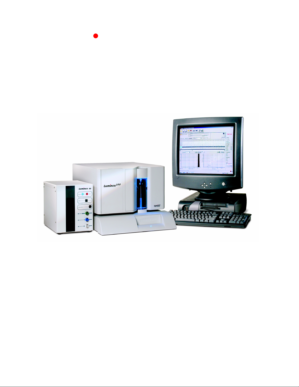
The Luminex® 100 system is a compact analysis unit consisting of a
Luminex 100 analyzer, the Luminex XY Platform (Luminex
XYP™), a PC, Luminex software, and reagents. The Luminex 100
analyzer integrates optics, fluidics, and advanced signal processing in
a 17 inch by 20 inch footprint. The Luminex XYP provides efficient
handling of 96-well microtiter plates. The PC uses Luminex software
to control the analyzer. The optional Luminex Sheath Delivery
system (Luminex SD™) is used to provide sheath fluid directly from
a 20 liter container.
Photodiodes and a photomultiplier tube receive fluorescent signals
from xMAP
and delivers the signals to a digital signal processor (DSP).
Proprietary algorithms function with the DSP to greatly increase the
sensitivity.
®
microspheres. The analyzer digitizes the waveforms
Hardware and preloaded software simplify installation and setup, and
with the help of this manual, you will be able to begin using xMAP
technology.
Principle of
Operation
PN 89-00002-00-063 Rev. A 1 - 1
The Luminex 100 system analyzes immunoassays, complex genetic
analyses, and enzymatic assays in one simple format. The reactants
(antibodies, oligonucleotides, substrates, etc.) of these assays are
anchored to the surfaces of uniquely fluorescent microscopic beads,
called microspheres. The unique fluorescent emission spectra of a
given microsphere identifies each of the assays performed
simultaneously on a single sample.
The Luminex 100 analyzer individually analyzes xMAP
microspheres in a flow stream. Every xMAP microsphere is
accurately classified to its own subset, based on its fluorescent
Page 12

Luminex 100 User Manual Version 1.7 xMAP Technology
signature. In addition, the Luminex 100 analyzer scans each
microsphere for the presence of a reporter fluorescence that
quantifies the assay at the microsphere’s surface.
The Luminex XYP works with 96-well plates that are no thicker than
0.75 inches. If you are not using the heater block, any brand of
microtiter plate that meets this size requirement will work. If you are
using the heater block, we recommend one of these two plates:
• Polyfiltronics
black.
•Costar
The system reads the wells in column-first order. An entire column
of wells is read; that is, well A1, B1, C1, D1, and so on to the end of
the column. Then the XY Platform moves over to the next column
and reads well A2, B2, C2, D2, and so on. When placing a plate on
the plate holder, place it so well A1 is in the upper-left corner of the
holder. You can run an entire plate, a consecutive range of samples
from the plate, or a single sample from the plate.
®
model P.
®
96-well plate, 200 µL, catalog #7703-1902,
Thermowell® 96-well plate, thin-wall polycarbonate,
Basic Concepts Luminex has pioneered a versatile and robust technology for the
measurement of soluble analytes. The Luminex 100 system performs
simultaneous, discrete measurements of multiple microsphere-based
reactions from a single specimen aliquot. A clear understanding of
the concepts and functionality associated with the instrument and
xMAP microspheres contributes to greater success with this
technology. We present a brief overview of some of the basic
concepts. For more information, refer to Practical Flow Cytometry,
4th edition, by Howard M. Shapiro, M.D. (New York: Wiley-Liss
Inc., 2003).
Fluidics There are two fluidic paths in the Luminex 100 analyzer. The first
path is a syringe-driven mechanism that controls the sample uptake.
This mechanism permits small sample uptake volumes from small
reaction volumes. The syringe-driven system transports a userspecified volume of sample from a microtiter plate to the cuvette.
The sample is injected into the cuvette at a steady rate for analysis.
After analysis, the sample path is purged with sheath fluid by the
second fluidics path. This process expels sheath fluid into the sample
container and effectively removes residual sample within the tubing,
valves, and probe. The second fluidics path is driven under positive
air pressure and supplies sheath fluid to the cuvette.
1 - 2 PN 89-00002-00-063 Rev. A
Page 13

xMAP Technology Introduction
Excitation The excitation system in the Luminex 100 analyzer uses two solid-
state lasers. A reporter laser excites fluorescent molecules bound to
biological reactants at the microsphere surface, and a classification
laser excites fluorochromes embedded in the microsphere. The lasers
illuminate the xMAP microspheres as they flow single-file through
the cuvette. These fluorescent signals are discriminated with
selective emission filters and are converted into intensity units by a
digital signal processor.
xMAP Microspheres The xMAP microspheres are highly uniform, polystyrene particles
that have been crosslinked during polymerization for great physical
and thermal stability. Varying amounts of fluorochromes embedded
within each microsphere give each microsphere set an unique
fluorescent signal. To ensure the stability of this address, it is
essential to protect the xMAP microspheres from light. Do not
subject xMAP microspheres to prolonged high temperatures, and
protect them from freeze/thaw manipulations.
Reporter Fluorochromes Each xMAP microsphere is dyed to emit light in a certain
classification channel. All xMAP microspheres of a given emission
represent a distinct assay within a multiplex of assays. A reporter
channel is used to detect fluorescence bound to the surface of each
microsphere, and each reporter emission quantitates each of the
distinct assays. Only one reporter emission is used for multi-analyte
assays in the Luminex 100 analyzer. The Luminex 100 analyzer uses
an excitation wavelength of 532 nm, and has an emission wavelength
of 575 nm ± 12 nm.
Fluorochromes R-Phycoerythrin, and Alexa
Luminex 100 analyzer, but you are not limited to these two. You may
have success using other fluorochromes such as Cyanine 3.
Phycoerythrin
Formula weight (Daltons) 240,000 470
Absorbance max (nm) 480, 546, 565 531
Extinction max (M
-1cm-1
)
1,960,000 83,800
532 work well with the
®
R-
Alexa
532
Emission max (nm) 578 554
Quantum yield 0.82 0.8
PN 89-00002-00-063 Rev. A 1 - 3
Page 14

Luminex 100 User Manual Version 1.7 xMAP Technology
Fluorescence
Compensation
Repetitive Microsphere
Measurements
Fluorescent spillover occurs when an emission spectrum overlaps
other emission criteria; therefore, selective filtering cannot occur. In
most analyzers, emission spillover is corrected using a technique
called compensation. Compensation involves subtraction of emission
percentage from another emission signal. In the Luminex 100
system, compensation is not necessary—the reporter signal does not
spill over into classification emissions.
Bound to reagents at the surfaces of the xMAP microspheres, the
reporter provides raw analytical data. Because a microsphere
suspension provides near liquid phase reaction kinetics, each
microsphere theoretically binds an equal number of reporter
molecules. Equal binding results in a statistically even distribution of
reporter on each microsphere in a set. When the Luminex 100
analyzer registers numerous events for each set, the system reports
individual population values based on an even coating of reporter.
This means that numerous replicates for each microsphere population
are measured from a single reaction vessel. The confidence in a
given measurement strengthens with increased replicate
measurements. For adequate confidence, 100 collected events per
microsphere set in each reaction vessel is usually sufficient.
Measurements are reported as the median for the xMAP
microspheres having a specific color signal.
About this Manual This manual introduces you to the Luminex 100 system. With step-
by-step instructions, the manual guides you through initial setup and
powering-on procedures. Next, it offers a concepts section which
describes some of the key topics encountered during system
operation. Once you have a working knowledge of the analyzer, the
manual’s text and figures lead you through the data collection
process, giving detailed explanations of available options and
offering examples when necessary. Glossary and troubleshooting
sections assist as references. In short, this manual instructs you
through each operational stage—from unpacking the Luminex 100
analyzer and XYP to collecting your data.
The conventions in this document assume a basic familiarity with
computers and a knowledge of Windows
document only one method of accessing a command, although many
commands are available through more than one method, such as
1 - 4 PN 89-00002-00-063 Rev. A
®
software. We typically
Page 15

xMAP Technology Introduction
from the main menu bar, from the toolbar, and from menus that
appear when you right-click an area of the screen.
Technical
Assistance
You can find answers to frequently asked questions (FAQs) on our
website: http://luminexcorp.custhelp.com.
Technical assistance is available to users in the U.S. and Canada by
calling toll free 1-877-785-BEAD (1-877-785-2323) between the
hours of 7:00 a.m. and 7:00 p.m. Central Time, Monday through
Friday. Users outside of the U.S. and Canada can call us at +1 512381-4397 between the hours of 7:00 a.m. and 7:00 p.m. Central
Time, Monday through Friday.
Inquiries may also be sent by email to support@luminexcorp.com.
PN 89-00002-00-063 Rev. A 1 - 5
Page 16

Luminex 100 User Manual Version 1.7 xMAP Technology
1 - 6 PN 89-00002-00-063 Rev. A
Page 17

Safety
Your safety is important. Please do not perform procedures on your
Luminex 100 system that are not specifically contained in this
manual, unless you are directed to do so by Luminex Technical
Support. This chapter discusses the following safety topics
• Intended Use
• Symbols
• Safety Precautions
Intended Use The Luminex 100 analyzer is designed for a wide range of indoor
laboratory testing applications measuring biomolecular reactions on
the surfaces of xMAP microspheres. This system is intended for
indoor research use only and not for use in diagnostic procedures.
The Luminex XYP instrument is intended for use with the Luminex
100 analyzer. With the Luminex XYP, you can process 96-well
microtiter plates without handling individual samples. The Luminex
XYP works with microtiter plates that are no thicker than 0.75 in.
Symbols These symbols describe warnings, cautions, and general information
used in the operation of this analyzer.
Symbol Description
1 Alternating current
2 Protective ground
3On
PN 89-00002-00-063 Rev. A 2 - 1
Page 18
Luminex 100 User Manual Version 1.7 xMAP Technology
Symbol Description
4Off
5 Warning (see manual).
6 Warning (see manual).
7 Warning (see manual).
8 Warning (see manual).
9 Warning (see manual).
10
Warning (refer to manual)
Warnings and Notes Informational notes and warnings may appear in this manual.
Note: A note provides general helpful information. No safety or
performance issues are involved.
Caution: This message is used in cases where the hazard is minor or
only potential hazard is present. Failure to comply with the caution
may result in potentially hazardous conditions.
Warning: This message is used in cases where danger to the
operator or to the performance of the instrument is present. Failure to
comply with the warning may result in incorrect performance,
instrument failure, invalid results, or hazard to the operator.
Danger: This message is used in cases where significant risk of
serious injury or death is present.
Safety Precautions Please read the following safety information before setting up or
using the Luminex 100 system. A user should always be present
during system operation. This system contains electrical, mechanical,
and laser components which, if handled improperly, are potentially
harmful. In addition, biological hazards may be present during
Luminex 100 analyzer operation. Therefore, Luminex Corporation
recommends that all Luminex 100 analyzer users become familiar
2 - 2 PN 89-00002-00-063 Rev. A
Page 19
xMAP Technology Safety
with the specific safety advisories below, in addition to adhering to
standard laboratory safety practices. The protection provided by the
equipment may be impaired or the warranty voided if the equipment
is used in a manner not specified by Luminex Corporation.
Electrical The Luminex 100 analyzer and Luminex XYP must be connected to
approved power sources.
Do not perform any maintenance or cleaning of the system’s
electrical components (except for the fuses).
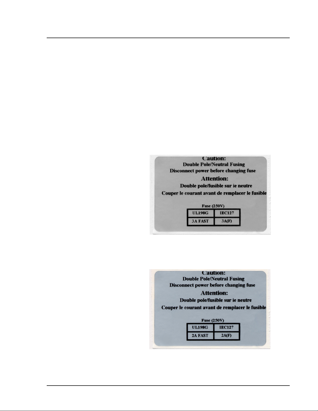
This caution label appears on the back of Luminex 100 analyzers
using the Coherent laser, and on the Luminex XYP:
Figure 2-1. Fuse Replacement Warning Label
This label appears on the back of Luminex 100 analyzers using the
Uniphase laser:
Figure 2-2. Fuse Replacement Warning Label - Uniphase Laser
PN 89-00002-00-063 Rev. A 2 - 3
Page 20
Luminex 100 User Manual Version 1.7 xMAP Technology
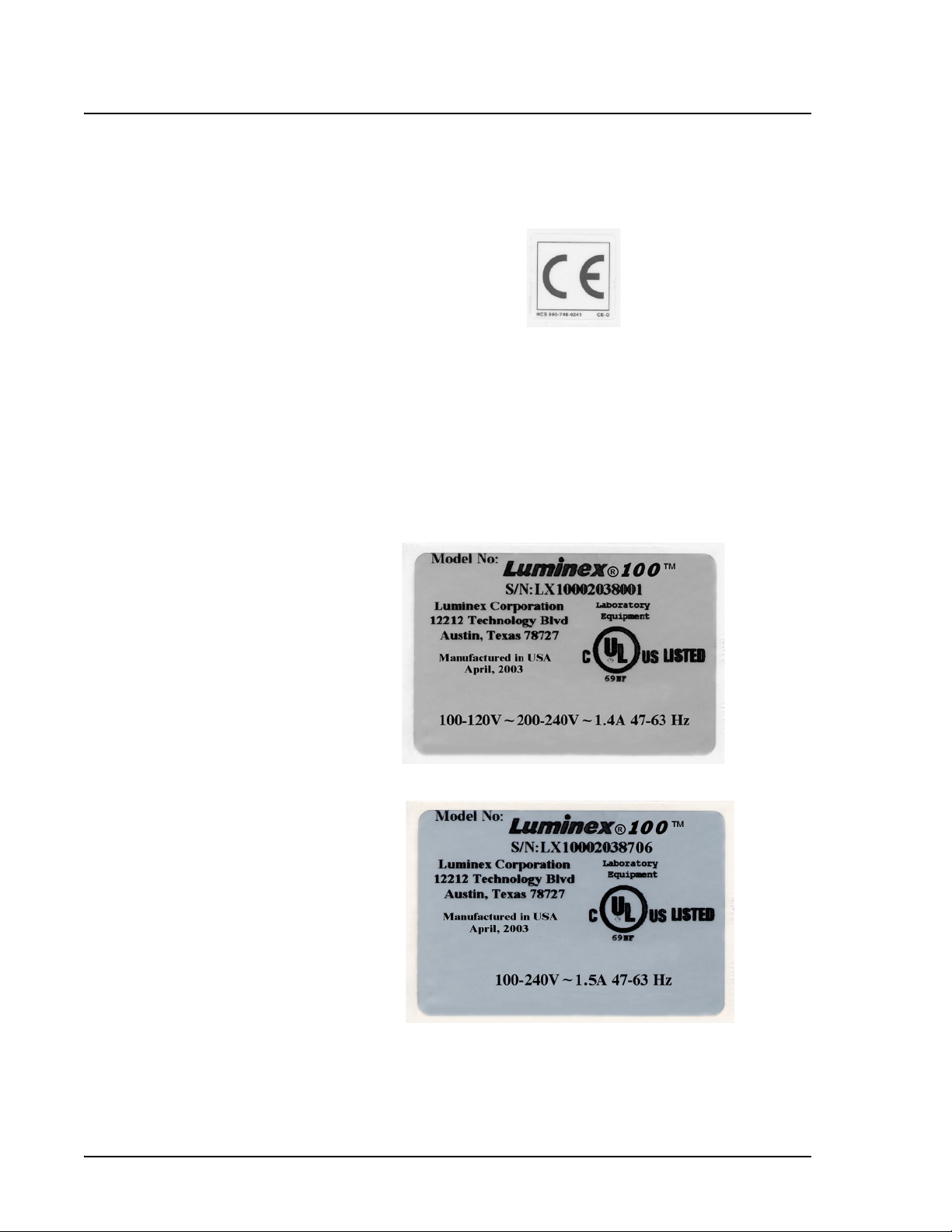
This label appears on the back of the Luminex 100 analyzer and the
Luminex XYP.
Figure 2-3. European Safety Requirements Label
The Luminex 100 analyzer complies with European Union (EU)
safety requirements and, therefore, may be marketed in the Europe
Single Market.
One of the following voltage labels displays on the back of the
Luminex 100 analyzer, depending if the instrument uses a Coherent
or Uniphase laser:
Figure 2-4. Luminex 100 Voltage Label (Coherent)
Figure 2-5. Luminex 100 Voltage Label (Uniphase)
2 - 4 PN 89-00002-00-063 Rev. A
Page 21
xMAP Technology Safety
This voltage label displays on the back of the Luminex XYP:
Figure 2-6. Luminex XYP Voltage Label
Fluidics The Luminex 100 analyzer contains fluidics. In the event of a fluid
leak, turn off all power to the system and disconnect all power cords.
Warning: If the system is used
to test biological samples, use
your standard laboratory safety
practices when handling system
waste.
Remember that the on/off switch is not a disconnect means - the
power cord must be removed from the outlet. Contact Luminex
Corporation for further information.
You must manually monitor waste levels. Do not allow the waste
container to overflow. Empty the waste container each time you fill
the sheath fluid container. Do not place the waste container on top of
the analyzer.
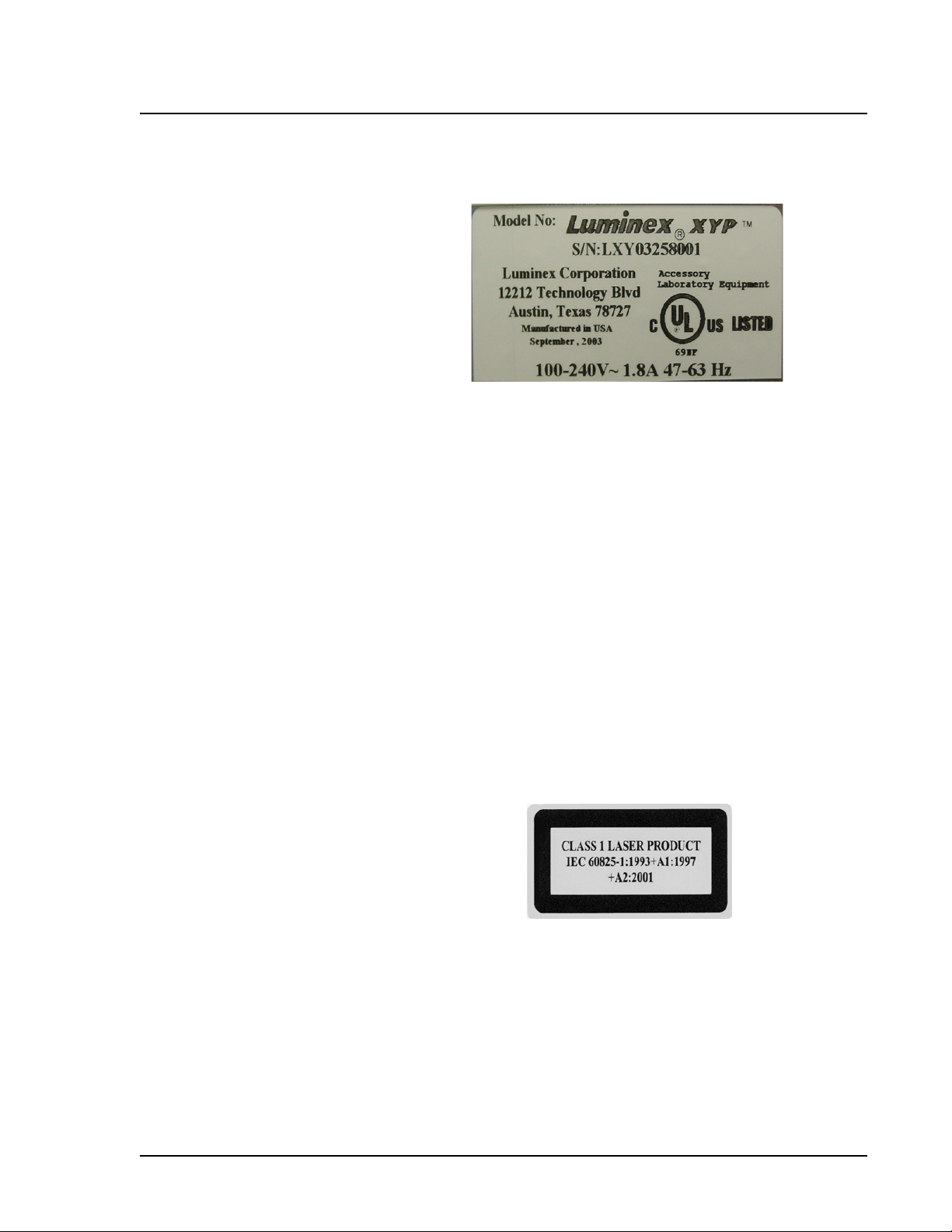
United States and international regulations require the following
warnings to appear on the analyzer during operation and
maintenance.
This label appears on the back panel of the analyzer:
Figure 2-7. Laser Class Label
PN 89-00002-00-063 Rev. A 2 - 5
Page 22
Luminex 100 User Manual Version 1.7 xMAP Technology
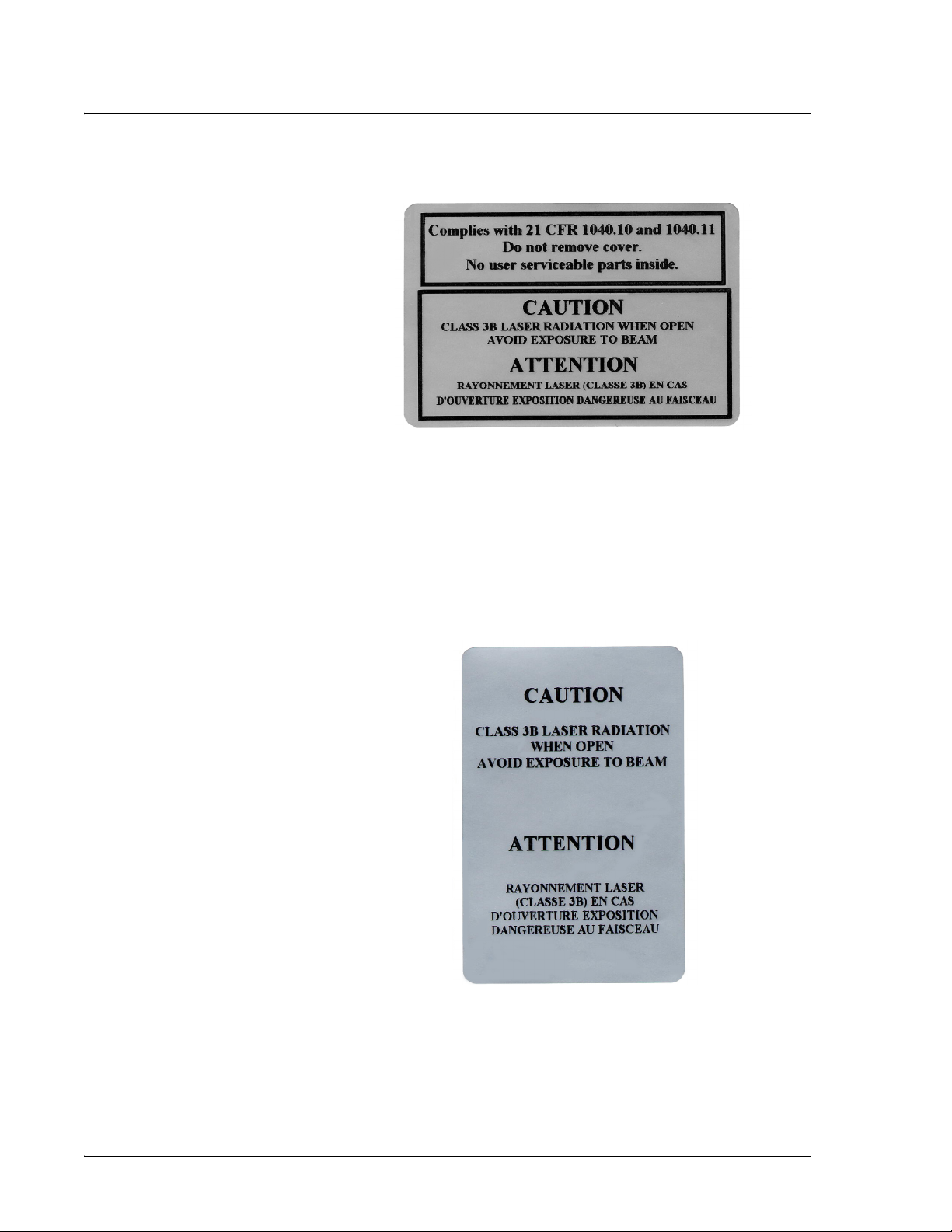
This label appears on the back panel of the Luminex 100 analyzer:
Figure 2-8. Laser Caution Label
Do not remove the analyzer cover. When performing routine
maintenance, ensure that power to the analyzer is OFF and the power
cord is disconnected.
All laser apertures in the analyzer are contained within a protective
housing. This label appears on the optics cover within the Luminex
100 analyzer.
Figure 2-9. Laser Caution Label on Optics Cover
This label appears above the laser apertures located inside the optics
enclosure inside the Luminex 100 analyzer.
2 - 6 PN 89-00002-00-063 Rev. A
Page 23
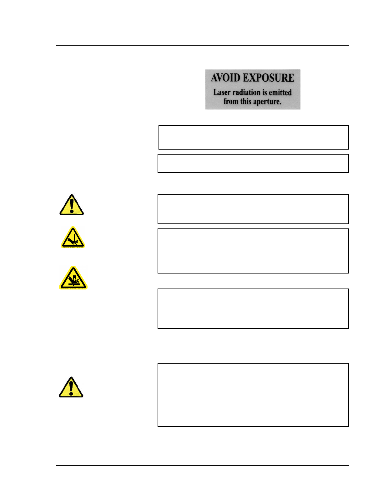
xMAP Technology Safety
Figure 2-10. Avoid Exposure Label
Caution: Use of controls or adjustments or performance of
procedures other than those specified herein may result in
hazardous radiation exposure.
Caution: To avoid exposure to hazardous radiation, only perform
procedures and adjustments as specified in this manual.
Mechanical
Warning: During operation, this system contains exposed,
moving parts. Risk of personal injury is present. Observe all
warnings and cautions.
Note: Access doors must be
closed while operating the
instrument. An operator must
be present during operation of
the instrument.
Biological
Warning: During operation, this system contains exposed,
moving parts which could result in puncture hazard. Risk of
personal injury is present. Keep hands and fingers away from the
sample probe. Keep hands and fingers out of the Luminex XYP
slot during operation.
Warning: During operation, this system contains exposed,
moving parts which could result in pinch point hazard. Risk of
personal injury is present. Keep hands and fingers away from the
syringe arm.
Warning: Human/animal samples may contain biohazardous
infectious agents. Where exposure (including aerosol) to potentially
biohazardous materials exists, follow appropriate biosafety
procedures and use personal protective equipment, such as gloves,
gowns, laboratory coats, face shields or masks, eye protection, and
ventilation devices. Observe all local, state, and federal biohazard
handling regulations when disposing of biohazardous waste
material.
PN 89-00002-00-063 Rev. A 2 - 7
Page 24

Luminex 100 User Manual Version 1.7 xMAP Technology
Heat
Warning: The heater plate of the Luminex XYP may be hot and
could cause personal injury if touched. Do not touch the heater
plate.
Blue Indicator Light
The blue light above the sample arm simply indicates the on/off
status of the instrument, and is harmless. The blue light emitting
diode (LED) does not emit light in the UV spectrum.
2 - 8 PN 89-00002-00-063 Rev. A
Page 25

System Overview
3
Hardware The Luminex 100 Version 1.7 system includes a Luminex 100
Version 1.7 analyzer, the Luminex XYP, and a PC.
The Luminex 100 analyzer includes the following hardware:
• Luminex 100 analyzer
• Sample tube holders (1.5 mL and 1.2 mL)
• Sheath fluid container
• Waste container
• Communications cable to connect analyzer with computer
The Luminex XYP includes the following hardware:
• Luminex XYP instrument
• Power cord
• Communication cable to connect to the Luminex XYP
• Alignment guide
• Luminex XYP sample probe (long probe)
• Reservoir
•Shield
• Luminex XYP heater block
• Probe alignment toolkit
• Allen wrench, 3/32 inch hexagonal
The PC includes the following hardware:
• Computer: a Pentium
• Monitor
• Power cords
• Keyboard
•Mouse
PN 89-00002-00-063 Rev. A 3 - 1
®
microprocessor class PC
Page 26

Luminex 100 User Manual Version 1.7 xMAP Technology
In addition, you can purchase the optional Luminex Sheath Delivery
system (Luminex SD).
xMAP Reagents • xMAP classification calibration microspheres (CAL1)
• xMAP reporter calibration microspheres (CAL2)
• Sheath fluid
Software Luminex Data Collector software provides complete control of the
Luminex 100 analyzer and performs real-time digital analysis of
assays. The Luminex 100 system is preloaded with the Luminex
software. However, we supply a software CD in case you need to
reinstall the software.
Luminex 100
Analyzer
Specifications
General • Operating temperature: 15°C to 30°C (59°F to 86°F)
• Storage temperature: 0°C to 50°C (32°F to 122°F)
• Humidity: 20% to 80%, noncondensing
• Altitude: designed to operate up to 2400 m (7874 ft.) above
mean sea level
• Physical dimensions: 43 cm (17 in) W x 51 cm (20 in) D x 23 cm
(9 in) H
• Weight: 23 kg (60 lbs)
• UL installation category: UL Installation Category II, as defined
in Annex J of UL 61010A-1
• Pollution degree: UL Pollution Degree 2, as defined in section
3.7.3.2 of UL 61010A-1
Power • Input voltage range:
• 100-240 V~, 1.5 Amps, 47-63 Hz
OR
• 100-120 V~ and 200-240 V~, 1.4 Amps, 47-63 Hz. See label
on rear of instrument.
• AC inlet fuse: 3A, 250V~, Fast Acting
OR
2A, 250 V~, Fast Acting. See label on rear of instrument.
• Shipping and storage: allowable shipping and storage
temperature and humidity ranges, 0°C to +50°C and 20%-80%
noncondensing, respectively.
3 - 2 PN 89-00002-00-063 Rev. A
Page 27

xMAP Technology System Overview
Laser • Reporter laser: 532 nm, nominal output 10-16.5 mW, maximum
500 mW, frequency-doubled diode; mode of operation mW,
continuous wave (CW)
• Classification laser: 635 nm, nominal output 9.1 mW ± 6%,
maximum output 25 mW, diode; mode of operation, continuous
wave (CW)
Fluidics • Sheath flow rate: 90 µL/second ± 5 µL/second
• Cuvette: 200 micron square flow channel
• Sample injection rates: 60 µL/minute, 45 µL/minute, or 30 µL/
minute
• Sample uptake volume: 10-200 µL
Electronics • Reporter channel detection: photomultiplier tube,
A/D resolution, 14 bits
• Classification and doublet discriminator channel detection:
avalanche photo diodes (APD) with temperature
compensation, A/D resolution 12 bits
• Communications interface: RS 232
Signal Processing • Signal modes: linear, with logarithmic or linear display option
PC • Computer: a Pentium III microprocessor or equivalent class PC,
minimum speed 933 MHz
• Main memory: minimum of 128 MB
• Hard disk drive: 10 GB minimum storage capacity
• Communications, serial ports: minimum of 2 RS-232 compatible
serial ports
• Operating system support: MS
• CE marked and UL listed
• Two-button mouse or equivalent
• Monitor: minimum of 17-inch diagonal monitor
• Keyboard: a 104-key keyboard or equivalent
• Power cords for the US and Canada are included in the system.
Power cords for other countries must be ordered separately.
• Power: 115-230 V~, Maximum 6.0 Amps, 50-60 Hz
Windows
®
PN 89-00002-00-063 Rev. A 3 - 3
Page 28

Luminex 100 User Manual Version 1.7 xMAP Technology
Luminex XYP
Specifications
General • Operating temperature: 15°C to 30°C (59°F to 86°F)
• Humidity: 20% to 80%, noncondensing
• Altitude: designed to operate at 2400 m (7874 ft.) above mean
sea level or below.
• Physical dimensions: 44 cm (17.25 in) W x 61 cm (24 in) D x 8
cm (3 in) H
• Weight: 14.5 kg (32 lbs)
• UL installation category: UL Installation Category II, as defined
in Annex J of UL 3101-1.
• Pollution degree: UL Pollution Degree 2, as defined in section
3.7.3.2 of UL 3101-1.
• Heater operating range: 35°C to 60°C (95°F to 140°F) with
tolerance 0°C to +2°C.
• Shipping and storage: allowable shipping and storage
temperature and humidity ranges, 0°C to +50°C and 20%-80%
noncondensing, respectively.
Power • Input voltage range: 100-240 V~, 1.8 Amps, 47-63 Hz
• AC Inlet Fuse: 3 Amp, 250 V~, Fast Acting
Electronics Communications interface: RS-232
Recommended
Equipment
You may find the following items helpful to protect the electronic
components of your Luminex 100 System.
Printer We recommend that you have a printer installed to your system so
that you can print reports and diagnostics. We recommend an HP
LaserJet 2200 printer.
Uninterruptible power
supply (UPS)
Luminex highly recommends using an uninterruptible power supply
(UPS) to protect your system from a power outage. Choose a supply
that can provide 1050 Watts for at least 45 minutes. The UPS should
be UL listed and CSA certified. The UPS also needs to be CE
marked if used internationally.
Surge Protector If you do not use a UPS, use a surge protector. Choose a protector
that meets your needs. Factors to consider include electrical
environment, endurance, suppressed voltage rating, and method of
protection. It should have six outlets, be rated at least 1500 Watts,
and be UL listed, CSA certified, CE marked for nondomestic use
when used internationally.
3 - 4 PN 89-00002-00-063 Rev. A
Page 29
xMAP Technology System Overview
Luminex 100
Analyzer Overview
The Luminex 100 analyzer consists of three subsystems: electronic,
fluidic and optical. The following section describes the useraccessible components of each subsystem. Chapter 7, "Maintenance
and Cleaning", describes routine maintenance for each of these
components.
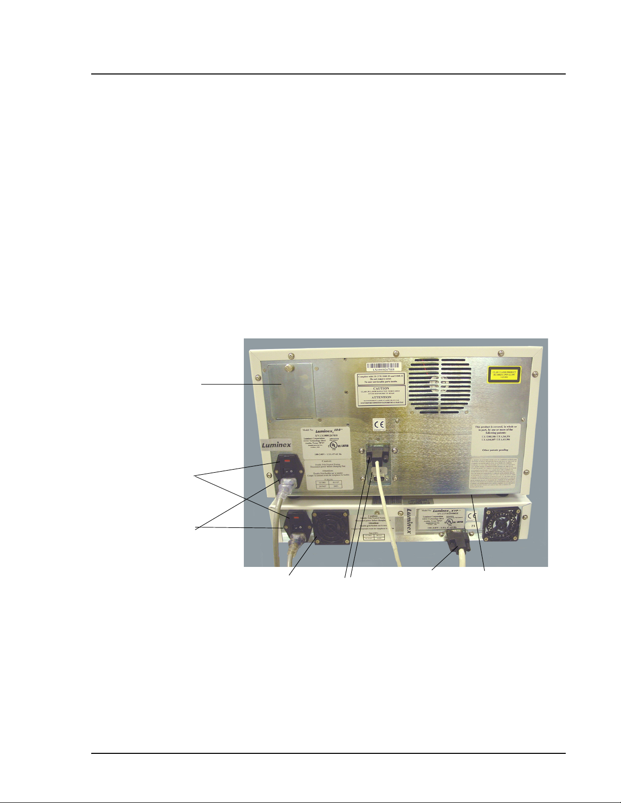
Electronic Power input module: Houses the analyzer on/off switch and
fuses.
P1 communications port (DB9): Connects the Luminex 100
analyzer to the computer.
Analyzer ventilation filter: Provides filtration for the analyzer
ventilation system. To ensure proper ventilation, do not obstruct the
area below the analyzer. Allow at least two inches of clearance
around the analyzer.
Air Intake Access Door
h
c
i
t
w
S
er
w
o
P
Power Input Module
XYP Instrument
Ventilation Filter
PN 89-00002-00-063 Rev. A 3 - 5
Communications
Ports (DB9)
Figure 3-1. Rear View of Luminex 100 Analyzer
XYP to PC
Serial cable
Analyzer
Ventilation Filter
Page 30
Luminex 100 User Manual Version 1.7 xMAP Technology
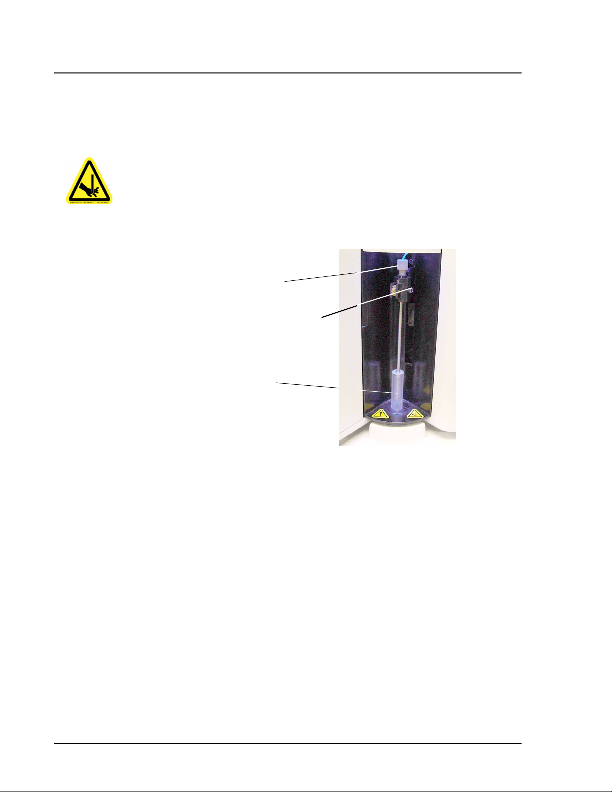
Fluidic Sample Arm: Transports the sample from the sample plate to the
cuvette. Upon operation, the carriage drops automatically to the
sample plate for sample retrieval.
Sample Probe: Acquires sample from the sample plate.
Warning: During operation,
this system contains exposed,
moving parts which can cause
puncture wounds. Risk of personal injury is present. Keep
hands and fingers away from the
sample probe.
Note: The probe shield is not in
place for this photo. You should
always replace the probe shield
before operating the system.
Cheminert
® fitting: Holds the sample probe in place. Use the
wheel to adjust the sample probe height.
Alignment Guide: Directs the sample probe into the Luminex
XYP instrument.
Cheminert
Fitting
Vertical Adjustment
Screw
Alignment
Guide
Figure 3-2. Sample Uptake Components
Access doors: There are two access doors on the face of the
analyzer. The center door provides access to the syringe. The left
door provides service panel access. Inside the left door, a bracket
holds the heater block for the Luminex XYP. There is also a clip for
the allen wrench included with the Luminex 100 analyzer.
3 - 6 PN 89-00002-00-063 Rev. A
Page 31

xMAP Technology System Overview
Left Door, Access
to Service Panel
Figure 3-3. Front View of Luminex 100 Analyzer Showing Access Doors
Center Door,
Access to Syringe
Air filter and access door: Cleans the air used to pressurize
sheath fluid. This filter is enclosed behind an access door located on
the back of the Luminex 100 analyzer.
Figure 3-4. Air Filter on Rear of Instrument
PN 89-00002-00-063 Rev. A 3 - 7
Page 32

Luminex 100 User Manual Version 1.7 xMAP Technology
Syringe: Delivers sample from the sample plate to the cuvette. It is
located in the compartment behind the center door.
Syringe
Seal
Syringe
Figure 3-5. Syringe
Sheath filter: Removes particles greater than 10 microns in
diameter from the sheath fluid. It is located behind the left access
door.
Sheath Filter
Assembly
Figure 3-6. Sheath Filter Assembly
Air, waste fluid, and sheath fluid connectors: Connect to the
sheath and waste fluid containers. The air connector is green, the
sheath fluid connector is blue, and the waste fluid connector is
orange.
3 - 8 PN 89-00002-00-063 Rev. A
Page 33

xMAP Technology System Overview
Sheath Fluid
Connector (Blue)
Figure 3-7. Left Side of Analyzer - Air and Fluid Connectors
Air Connector
(Green)
Waste
Connector
(Orange)
Sheath fluid container (not shown): Holds sheath fluid. For
proper operation, place the container at the same level as the
analyzer. Do not place the container on top of the Luminex 100
analyzer.
The sheath fluid level should be below the air inlet connection and
above the sheath outlet connection. Sheath fluid levels must be
monitored manually. Check the sheath fluid level before starting a
run or procedure.
Waste fluid container (not shown): Receives waste from the
system. Monitor the waste fluid levels—do not allow the waste
container to overflow! Empty the waste container each time you fill
the sheath fluid container. Do not put the waste container on top of
the Luminex 100 analyzer.
Optical The optical system contains the optics assembly and the excitation
lasers. The optical assemblies do not require user adjustment.
PN 89-00002-00-063 Rev. A 3 - 9
Page 34

Luminex 100 User Manual Version 1.7 xMAP Technology
Luminex XYP
Instrument
The Luminex XYP is a self-contained system. There is one access
door that contains a plate holder and a reservoir. A heater plate can
be placed in the plate holder.
Overview
Reservoir You can use 70% isopropanol or 70% ethanol, deionized water, and
10%-20% bleach solution in the reservoir for Luminex 100 analyzer
cleaning and maintenance procedures.
Heater Block Use the heater block as required by your assay procedures. When
you are not using the heater block you can store it in the bracket
inside the left access door of the Luminex 100 analyzer.
3 - 10 PN 89-00002-00-063 Rev. A
Page 35

4
Installation
Luminex 100
System Installation
Note: The Luminex 100 System is
too heavy for one person to lift
alone. Two people should unpack
and lift the system to the
workbench.
Ensure that the facility complies with all system and safety
requirements.
If you are using the optional Luminex SD, install it after completely
installing the Luminex 100 analyzer and the Luminex XYP. See the
Luminex Sheath Delivery System appendix for instructions.
To set up and start up the Luminex 100 system:
1. Unpack the Luminex 100 analyzer, Luminex XYP instrument,
and the PC. Review the hardware list on page 3-1 and identify
each system component.
2. Place the Luminex XYP on a clean, flat surface.
3. Remove the red shipping pin. Leave the silver knob in place.
Shipping Pin
Figure 4-1. XYP With Shipping Pin in Place
4. Attach the power cord and the communication cable to the
Luminex XYP. Do not plug the power cord into the outlet.
5. Place the Luminex 100 on top of the Luminex XYP. Do not plug
it into the power outlet.
PN 89-00002-00-063 Rev. A 4 - 1
Page 36

Luminex 100 User Manual Version 1.7 xMAP Technology
6. Replace the short sample probe with the long sample probe as
follows: Unsnap the light housing above the probe. Loosen the
Cheminert fitting that holds the sample probe in place. Gently
grasp the probe and push up. Remove the sample probe out of
the top of the sample arm. Push the long sample probe into the
top of the sample arm, and tighten the Cheminert fitting.
7. Install the alignment guide by screwing it into the Luminex XYP
as shown below. Adjust the position of the Luminex 100
analyzer with the Luminex XYP as necessary.
Alignment Guide
Figure 4-2. Front of Luminex 100 System, Alignment Guide in Place
8. Attach the waste container.
9. Fill and attach the sheath fluid container. Fill the container with
sheath fluid to just below the air intake.
To set up the PC:
1. Place the PC to the right of the Luminex 100 analyzer and
Luminex XYP. Do not place the PC on top of the analyzer.
2. Place the monitor on top of the PC and connect the cable
between the monitor and the PC.
3. Attach a power cable to the power input modules of the PC and
monitor. Do not plug the power cable into the power outlet.
4. Connect the mouse and keyboard to the PC.
5. Connect one of the communications cables between the Luminex
100 analyzer communications port and COM Port 1 on the PC.
6. Connect the other communications cable to between the XYP
instrument communications port to and COM port 2 on the PC.
7. Plug all instrument power cords into an approved power source.
4 - 2 PN 89-00002-00-063 Rev. A
Page 37

xMAP Technology Installation
Luminex 100
Software Setup
After performing the Luminex 100 system assembly, ensure that the
proper interface between the analyzer and PC is in place.
To set up the software:
1. Turn on the Luminex 100 analyzer, then turn on the PC. The
Luminex software launches automatically.
2. Click Ye s to accept the End-User License Agreement. If the
system does not prompt you to accept this agreement, read the
agreement shown after the title page of this manual. If you reject
the agreement, you cannot use the Luminex 100 system. Contact
Luminex Technical Support if you reject the agreement.
3. Verify that the analyzer status, shown in the System Monitor box
on the Luminex Main window, is at “Standby.” If the status is
“Bad Link,” exit the Luminex software and start it again.
4. On the Analyzer menu, click Setup. The Machine Setup dialog
box opens.
Figure 4-3. Machine Setup Dialog Box
5. Ensure that the analyzer type shown is Luminex 100.
6. Make sure that COM Port is set to 1. This setting refers to the
port on your computer, not on the Luminex 100 analyzer.
7. Make sure that the XY Port is set to 2. If communication
between the Luminex 100 analyzer and the Luminex XYP
instrument fails, switch ports so that the Luminex 100 analyzer is
on COM port 2 and the XY Port is set to 1. This task enables you
to check if the serial cable is the cause of the communication
errors.
PN 89-00002-00-063 Rev. A 4 - 3
Page 38

Luminex 100 User Manual Version 1.7 xMAP Technology
Adjusting the
Sample Probe
Height
Note: Adjusting the sample probe
vertical height is critical.
You must adjust the Sample Probe vertical height each time you
install a Sample Probe, change the type or style of microtiter plate,
or move the instrument.
Thumb Wheel
ent
m
t
s
u
dj
A
t
i
gh
e
H
ew
c
r
S
g
i
n
k
Loc
Figure 4-4. Sample Probe Height Adjustment Tools
To adjust the Sample Probe’s vertical height:
1. Turn on the Luminex XYP and the Luminex 100 analyzer, and
PC. Wait for the Luminex Data Collector software to start.
2. If already installed, remove the clear plastic shield covering the
sample probe area.
3. In a 96-well microtiter plate where overall height is no more than
0.75 inches, place the appropriate alignment tool in the plate.
• For a standard plate with flat-bottomed wells, stack two of
the larger (5.08 mm diameter) alignment disks in well A1.
• For filter-bottom plates, stack three of the larger alignment
disks into well A1.
• For half-volume plates with flat-bottomed wells, stack two
small (3.35 mm diameter) alignment disks in well A1.
• For a plate with conical wells, place one alignment sphere
into well A1.
• For round-bottom wells, stack 2 small disks in well A1.
4. Click Eject.
4 - 4 PN 89-00002-00-063 Rev. A
Page 39

xMAP Technology Installation
5. Place the 96-well microtiter plate on the Luminex XYP with
position A1 in the top left corner and click Retract to retract the
plate.
6. Use the 3/32 inch hexagonal allen wrench to loosen the height
adjustment locking screw. See the photo on page 4-4.
7. Click Options on the toolbar.
8. Click Setup XY, then click Setup. This dialog box appears:
9. Click Test to lower the sample probe into well A1.
10. Using the thumb wheel, raise and lower the Sample Probe until it
rests on, but does not apply pressure to, the top of the alignment
disk or sphere.
Note: To avoid adjusting the sample probe too low, open the
Luminex XYP door as you begin adjusting the probe height. The
plate should not bounce up or plunge down as you lower or raise
the sample arm. DO NOT PUT YOUR HAND INSIDE THE
LUMINEX XYP!
11. Use a 3/32 inch hexagonal allen wrench to tighten the height
adjustment locking screw.
12. Click Test to raise the Sample Probe, then click OK to close the
dialog box.
13. Replace the clear plastic shield that covers the Sample Probe
area.
PN 89-00002-00-063 Rev. A 4 - 5
Page 40

Luminex 100 User Manual Version 1.7 xMAP Technology
Installing Software
and Firmware
The Luminex 100 system arrives preloaded with the Data Collector
software. It is possible that you may need to reload the software at
some time.
To reinstall the software:
1. Backup log files. Copy your template directory and the file
named calibrationlog.mdb to a backup location. These files may
be found in the Luminex setup directory.
2. Uninstall the Luminex Data Collector software using the
Windows Add/Remove programs function. On the lower left
corner of your screen, click Start > Settings > Control Panel.
The Control Panel window opens. Click Add/Remove
Programs. The Add/Remove Programs window opens. Click
Luminex Data Collector, then click Change/Remove. Follow
the prompts throughout the rest of the removal process.
3. Insert the Luminex CD into the CD ROM drive. The program
manager beings installing the software, displaying instructions
when necessary.
4. Restart your computer after installing the Luminex software.
5. Copy your template file directory and the calibrationlog.mdb file
from the backup location toe the Luminex setup directory.
6. Verify that the firmware version, listed in the Help menu, is the
most recent version. Contact Technical Support to check this
information.
What to Do Next After you assemble and power the system, verify that your analyzer
is correctly installed and functions properly using the “Verification”
section beginning on page 8-14 in the “Troubleshooting” chapter.
You can find answers to frequently asked questions (FAQs) on our
website: http://luminexcorp.custhelp.com.
For assistance, contact Luminex Technical Support. Users in the U.S.
and Canada can call us at 1-877-785-BEAD (1-877-785-2323)
between the hours of 7:00 a.m. and 7:00 p.m. Central Time, Monday
through Friday. Users outside of the U.S. and Canada can call us at
+1 512-381-4397 between the hours of 7:00 a.m. and 7:00 p.m.
Central Time, Monday through Friday. Inquiries may also be sent by
email to support@luminexcorp.com.
4 - 6 PN 89-00002-00-063 Rev. A
Page 41

System Startup
Title B
This chapter describes how to start up your system. The topics
included are:
• Luminex Main Window - a tour of the Luminex Main window
• Setup - describes how to set up the system
• Calibration - describes how to calibrate the instrument, add new
lots of calibration microspheres, how to print calibration reports.
Luminex Main
Window
ar
Menu Bar
Tool Bar
Startup
Display
Status Bar
Use the Luminex software to start the system. To start the software
and open the main window, double-click the Luminex Data
Collector icon on the Windows desktop.
System
Monitor
Figure 5-1. Luminex Main Window
PN 89-00002-00-063 Rev. A 5 - 1
Page 42

Luminex 100 User Manual Version 1.7 xMAP Technology
The Luminex Main window has six components: Title bar, Menu bar,
Tool bar, Startup display, Status bar, and System monitor.
The Title bar shows the name of the software, and changes
depending on what section of the software you are using.
The Menu bar contains commands to set up the Luminex 100
analyzer and perform data acquisition. See Chapter 6 for more detail.
The Tool bar, also discussed in greater detail in Chapter 6, contains
icons for commands that are frequently used when running the
Luminex software.
The Startup display shows icons for many frequently-used
commands. You use most of these commands when starting the
system, acquiring data, and shutting the system down.
The Status bar shows the status of current software events.
The System monitor displays Device and Calibration status.
Calibration You should perform Luminex 100 analyzer calibration after system
installation, instrument service, whenever the system is moved, and
monthly with routine use. For optimal performance, calibrate the
instrument daily as part of your startup routine and whenever the d
Cal Temp temperature shown on the system monitor panel indicates
Add New Classification
Channel Calibration Lots
a change of more than 3 degrees Celsius (
xMAP microspheres with known light-scattering properties and
known fluorescent intensities in the reporter (RP1), classification 1
(CL1), and classification 2 (CL2) wavelength ranges. The calibration
process uses these xMAP microspheres to adjust voltage settings for
optimal and consistent microsphere classification and reporter
readings. Current calibrated settings automatically apply to any new
session.
Before you perform an initial calibration for the analyzer, and
whenever you receive a new supply of xMAP calibration
microspheres, enter the product and lot numbers and the calibration
target values.
°C). The calibrators are
5 - 2 PN 89-00002-00-063 Rev. A
Page 43

xMAP Technology System Startup
To add a new lot of xMAP classification calibration
microspheres:
1. Click Calibrate. The Start Calibration dialog box opens.
Figure 5-2. Start Calibration Dialog Box
2. Click New in the Classification Channel box. The Add New
Classification Calibrator dialog box opens.
Figure 5-3. Add New Classification Calibrator Dialog Box
3. Enter the information into the dialog box, using the values on the
Certificate of Quality that came with your xMAP calibration
microspheres. You do not need to enter a value for CL3;
however, you must click within the CL3 box and press Enter to
save the values.
4. Click OK. You can now use this classification channel xMAP
calibration microsphere lot to calibrate your instrument.
PN 89-00002-00-063 Rev. A 5 - 3
Page 44

Luminex 100 User Manual Version 1.7 xMAP Technology
Add New Reporter
Channel Calibration Lots
Before you perform initial calibration for the analyzer, and whenever
you receive a new supply of xMAP Calibration microspheres, enter
the product and lot numbers and the calibration target values.
To add a new lot of xMAP reporter calibration microspheres:
1. Click Calibrate. The Start Calibration dialog box opens.
Figure 5-4. Start Calibration Dialog Box
2. Click New in the reporter channel area. The Add New Reporter
Calibrator dialog box opens.
Figure 5-5. Add New Reporter Calibrator Dialog Box
3. Fill in the information on this dialog box using the values on the
Certificate of Quality Analysis included with your xMAP
calibration microspheres. Press Enter.
4. Click OK. You can now use this xMAP reporter channel
calibration microsphere lot to calibrate your instrument.
5 - 4 PN 89-00002-00-063 Rev. A
Page 45

xMAP Technology System Startup
Calibrate the Luminex 100
Analyzer
Note: Do not dilute the xMAP
calibration microspheres. Limit
exposure to light!
In addition to calibrating the analyzer after installation, you can
enhance optimal performance by calibrating the instrument daily as
part of your startup routine and whenever the d Cal Temp
temperature shown on the system monitor panel indicates a change
of more than 3 degrees Celsius (
°C).
To calibrate the Luminex 100 analyzer:
1. Turn on the Luminex 100 analyzer. Click Warmup on the main
screen, then click OK on the dialog box that appears. After the
30-minute warmup, go on to the next step.
2. Click Prime on the main screen. Click OK when you want to
begin the prime cycle.
3. Click Options on the toolbar and ensure that the default settings
for alcohol flush is set to Reservoir, and that the wells selected
for CAL1 and CAL2 correspond to the wells in the plate that you
want to use for calibration.
4. Vortex the xMAP calibration microspheres (CAL1 and CAL2).
5. Dispense 5 drops (~ 200 µL) of xMAP classification calibration
microspheres (CAL1) and 5 drops of xMAP reporter calibration
microspheres into the wells you designated in the Setup XY tab
of the options menu.
Place classification
calibrator in a well
(i.e., A1).
(You may assign
different well
locations, if
Place reporter
calibrator in a
well (i.e., B1).
1 2 3 4 5 6 7 8 9 10 11 12
A
B
C
D
E
F
G
H
Figure 5-6. 96-well Plate. Well A1 and B1 Filled
6. Click Eject on the toolbar and place the plate on the plate holder
with well A1 in the top, left-hand corner.
PN 89-00002-00-063 Rev. A 5 - 5
Page 46

Luminex 100 User Manual Version 1.7 xMAP Technology
7. Fill the reservoir with a solution of 70% isopropanol or 70%
ethanol. Click Retract on the toolbar to retract the plate holder.
8. Click Alcohol Flush, then click OK. The alcohol flush removes
air from the fluidics. This takes about 5 minutes.
9. Click Calibrate on the main screen. The Start Calibration dialog
box opens.
Figure 5-7. Start Calibration Dialog Box
10. Enter your name in the Operator text box.
11. Select the Product / Lot Number for the xMAP classification
calibration and reporter microspheres.
12. Click OK. The Calibration dialog box opens.
Figure 5-8. Calibration Dialog Box
13. Make sure Classification is selected, and click Start.
The progress bar shows the calibration progress, which should
take less than two minutes. If the status changes to “Sample
Empty” before calibration completes, a “Calibration Failed”
message appears. Click OK and restart the process. When
calibration finishes for the classification microspheres, a
5 - 6 PN 89-00002-00-063 Rev. A
Page 47

xMAP Technology System Startup
“Calibration Succeeded” message appears. The settings and any
comment you enter are logged into the calibration report.
14. Click OK in the confirmation dialog box. The Calibration dialog
box opens again.
15. Select Reporter and click Start. The progress bar shows you the
calibration progress. Calibration should take less than two
minutes. If the status in the system monitor changes to “Sample
Empty” before calibration completes, a “Calibration Failed”
message appears. Click OK and start the process again. When
calibration finishes for the reporter microspheres, a “Calibration
Succeeded” message appears. The settings and any comment you
enter are logged into the calibration report.
16. Click OK on the confirmation dialog box.
xMAP Calibration microspheres are very concentrated. Each
time you calibrate the instrument, follow it with 4 wash cycles
using deionized water or sheath fluid.
Preview or Print
Calibration Report
17. Click Eject from the toolbar and remove the plate.
18. Click Retract to retract the plate holder.
The calibration report is a quality control tool that shows the
frequency of past calibrations, operators of past calibrations, and
trends in instrument settings. The calibration report is available as a
log or as a detailed report.
To print or preview the calibration report:
1. Close all open sessions.
2. Click Print on the toolbar. The Print dialog box opens.
Figure 5-9. Print Dialog Box
PN 89-00002-00-063 Rev. A 5 - 7
Page 48

Luminex 100 User Manual Version 1.7 xMAP Technology
3. Check the box in front of the report type you want. You can
check both boxes to see both kinds of calibration report.
4. Click OK to print the calibration report, or Preview to see the
report on your screen. Figure 5-10 shows an example of a
calibration log. Figure 5-11 shows an example of calibration
detail report.
Figure 5-10. Calibration Log
The calibration log shows gain values associated with each
calibration. A gain value is a representation of the voltage. Use this
log to observe the gain values. If you see a spike in voltage (20 V or
more) in the gain value for a channel from one calibration to the
next, the difference may indicate a problem with the instrument. It is
normal to see a value of -1 for RP1 gain for classification
calibrations. You also see gain values of -1 listed for DD, CL1, and
CL2 for reporter calibrations.
5 - 8 PN 89-00002-00-063 Rev. A
Page 49

xMAP Technology System Startup
Analyzer menu
commands
Figure 5-11. Luminex Calibration Detail Report
The calibration detail report is often used by Luminex field service
personnel when performing system maintenance. The report shows
system temperature, Voltage, and pressure readings.
Use the Analyzer commands to prepare the Luminex 100 analyzer
for sample acquisition, analysis, and shut down. On the Analyzer
menu, choose the command you want to perform. Many of these
commands also have buttons on the main screen.
Calibrate: Opens the Start Calibration dialog box. See page 5-2 for
calibration procedures.
Setup: Opens the Machine Setup dialog box. System connections
must be defined with initial installation of the instrument, and again
if a Luminex XYP instrument is added to the system. See page 4-3
for more information.
Sanitize: Decontaminates the sample lines and cuvette after
biohazard contact. Use a 10%-20% bleach solution to sanitize the
system after running biohazardous samples. See page 7-3 for the
sanitizing procedure.
PN 89-00002-00-063 Rev. A 5 - 9
Page 50

Luminex 100 User Manual Version 1.7 xMAP Technology
Prime: Removes air pockets from the fluidic pathways. Use this
operation after system installation and following replacement of the
sheath fluid. Sheath fluid flows freely for several seconds followed
by a fill-and-purge action by the syringe. Repeat until the waste line
outside the instrument appears free of all significant air pockets.
Alcohol flush: Removes air bubbles from the walls of the cuvette.
Use 70% isopropanol or 70% ethanol for the alcohol flush solution.
After an alcohol flush, do 2 wash cycles with distilled water.
Wash cycle: Removes residual sample from the sample acquisition
lines. Place at least 200 µL of distilled water in the Luminex XYP
reservoir. After calibration, run 4 wash cycles with distilled water.
Back flush: Removes obstructions from the cuvette. Use this if
Note: Always follow a Back Flush
with a 70% isopropanol OR a 70%
ethanol Alcohol Flush. Follow the
Alcohol Flush with two distilled water
or sheath fluid wash cycles.
fluid does not flow through the waste tubing during prime cycles or
during sample acquisition. Routine back flushes are not
recommended; use back flush only as a troubleshooting method.
Drain: Temporarily drains the cuvette, then does a fill command.
Useful for cleaning debris buildup in the cuvette, or for clearing
bubbles from the cuvette. Routine drains are not recommended.
Sheath fluid is expelled at the end of the drain function.
Soak: Holds a solution in the fluidics lines for an extended time.
When shutting down the instrument overnight or for an extended
period of time, use a distilled water soak. Salt in the sheath fluid can
form salt crystals in the sample probe or instrument tubing. When
restarting the instrument, follow the routine startup procedure shown
on page 7-1 to re-equilibrate the system with sheath fluid. Before you
use the Soak command, place 1.2 mL of soak solution in the
Luminex XYP reservoir.
Warmup: Performs an initial 30-minute optics warmup. While
powered, the optics remain engaged for 4 hours after each
acquisition. After 4 hours of inactivity, the lasers automatically shut
off, and must be warmed up again before the next acquisition. If Start
is activated before warming up, an automatic 30-minute warmup
phase is started. The warmup phase can be cancelled using the
Cancel warmup command on the Analyzer menu. We strongly
recommend that you do not cancel warmup. Your test results will be
accurate only if the system is completely warmed up before you
begin acquisition. A complete warmup cycle is critical for accurate
calibration.
XYP Retract: Retracts the plate into the Luminex XYP slot.
Enable Heater: Warms the Luminex XYP heater block.
5 - 10 PN 89-00002-00-063 Rev. A
Page 51

Data Acquisition
6
The Luminex 100 analyzer uses Luminex Data Collector software to
acquire data. This chapter describes the following topics:
• Options
• Sessions
• Templates
• Multiplex Acquisition
• Data Collection
•Reports
Options Before you can acquire data, you must set up some of the different
options available. Click Options on the toolbar to open the Options
dialog box. The Options dialog box has these tabs: User, Acquisition,
Advanced, Setup XY, and Info. These options apply to all sessions.
User tab This tab has controls to set preferences for how the system works.
Figure 6-1. Options Dialog Box - User Tab
PN 89-00002-00-063 Rev. A 6 - 1
Page 52

Luminex 100 User Manual Version 1.7 xMAP Technology
Sound effects: Enables sounds during system operation.
Clear recent file list: Removes the list of recent files from the File
menu. Do this each time you want to clear the list of recent files.
Show project settings dialog on new session: Opens the project
settings dialog box when you start a new session. You can also click
Settings on the toolbar to open the settings dialog box.
Display full path of session on title bar: If this option is unchecked,
an abbreviated file name displays on the title bar.
Auto resize acquisition grid: Resizes the acquisition grid depending
on the length of text within each column.
Default beadmap: Controls the beadmap (or MAP) used when you
begin a session via the New Session button on the Main screen.
Click Browse to change the setting. Each MAP refers to a certain
combination of xMAP microspheres. The 100, 50, and 25 Region
MAPs are standard MAPs for multiple analyte data collection. Use
the Development MAP for development microspheres. The
Calibrator MAP and NoRegion MAPS are for system diagnostics.
094
093
092
034
019
013
008
004
084
074
063
053
044
035
027
020
014
009
085
075
064
054
045
036
028
021
015
040
031
023
016
010
005
001
071
060
050
041
032
024
017
011
006
002
082
072
061
051
042
033
025
018
012
007
003
083
073
062
052
043
026
Figure 6-2. 100 Region MAP
095
086
076
065
055
046
037
029
022
096
087
077
066
056
047
038
030
097
088
078
067
057
048
039
098
089
079
068
058
049
099
090
080
069
059
100
091
081
070
6 - 2 PN 89-00002-00-063 Rev. A
Page 53

xMAP Technology Data Acquisition
Acquisition tab On this tab you can select the default folder for your session files. If
you want a folder other than the one shown, click Browse and select
a different folder.
Figure 6-3. Options Dialog Box - Acquisition Tab
Advanced tab Use the Advanced Tab to set properties in the Luminex Data
Collector software. You can select multiple commands in this tab.
Figure 6-4. Options Dialog Box - Advanced Tab
Show Dot Plot. Enables toggling between a bar graph and dot plot.
Show Statistics. Displays all session statistics in the acquisition
window.
Show Prep Mode. Sets a gate before actually running an assay.
Show RP1 Gate. This is a Field Service option. Do not select this
option unless directed by Technical Support.
PN 89-00002-00-063 Rev. A 6 - 3
Page 54

Luminex 100 User Manual Version 1.7 xMAP Technology
Show APD Voltages. This is a Field Service option. Do not select
this option unless directed by Technical Support
Show Project Properties. This is a Field Service option. Do not
select this option unless directed by Technical Support.
View Calibration Detail. Shows the detail screen while calibrating
the instrument.
Allow FileMode. Enables use to replay previously run sessions.
Enable Liquid Handler. This is a Field Service option. Do not
select this option unless directed by Technical Support.
Info tab View the serial number, version numbers and build date. This
information is for display only; you cannot change it.
Figure 6-5. Options Dialog Box - Info Tab
Setup XY Tab This tab has controls to set preferences for how the Luminex XYP
operates.
Figure 6-6. Options Dialog Box - Setup XY Tab
6 - 4 PN 89-00002-00-063 Rev. A
Page 55

xMAP Technology Data Acquisition
To use the heater, check Enabled in the Heater area. Use the Set
Point control to select a temperature between 35
°C and 60°C (95°F
to 140°F). To maintain heater temperature between sessions, check
Hold Temperature between sessions checkbox. If this is not
checked, the heater turns off between acquisition sessions.
Warning: The heater plate is hot
when in use and may cause personal
injury. Do not touch the heater plate.
Allow the heater block to cool after
use before touching it.
To have the Luminex XYP automatically retract the plate holder
when you click Start, check the Auto Retract checkbox.
To consistently open a session in single sample mode, check Single
Sample Start Acquisition.
To control plate positions, use the controls in the Default Sample
Locations area. If you change these settings, be sure to select a
location that is large enough to hold the amount of sample required
for the command. The reservoir holds up to 3000 µL.
Command Size of location needed
Sanitize 1025 µL
Soak 275 µL
Back Flush 0 µL
Wash 200 µL
Alcohol Flush 1025 µL
Drain 200 µL
Click Apply and OK when you finish changing the options.
Sessions You must create a session in order to collect assay data. A session is
a folder that contains individual assay data and specified settings.
When you first open a session, the session uses default settings.
These default values reflect calibrated and recommended settings.
There are four ways to create a session:
• use default settings
• use a template
• open an existing session and add new data
• open an existing session and save as a new session.
PN 89-00002-00-063 Rev. A 6 - 5
Page 56

Luminex 100 User Manual Version 1.7 xMAP Technology
Create a Session Using
Default Settings
To create a session using default settings:
1. On the Luminex main window, click New Session. The Settings
dialog box opens. The values shown in the General tab are
recommended settings.
Figure 6-7. Settings Dialog Box - General Tab
2. Enter a name for the session in the Description field. Enter your
name in the Operator field. Modify other fields as necessary. A
full description of each of the fields begins on page 6-14. Click
OK.
Create a Session Using a
Template
3. When the analyzer finishes acquiring data, click save to save the
session under a folder heading of your choice.
To create a session using a template:
1. Click Tem pl at e on the toolbar to open the Choose a Template
dialog box.
Figure 6-8. Choose a Template Dialog Box
6 - 6 PN 89-00002-00-063 Rev. A
Page 57

xMAP Technology Data Acquisition
2. Select the template that you want to use for this session and click
OK. If the template already contains a beadmap (or MAP), the
template defaults to that MAP. If you have not yet selected a
beadmap, this Choose Bead Map dialog box opens:
Figure 6-9. Choose Bead Map Dialog Box
Select the MAP you want to use and click OK. The 100 Region,
50 Region, and 25 Region MAPs are the standard MAPs for
multiple analyte data collection. The Calibrator MAP is available
for system diagnostics. Use the Development MAP only with
development microspheres. Use the NoRegion MAP for system
diagnostics only.
3. In the save current settings dialog box, Type the name of the
session in the New folder field. Select the folder in which you
want to create the session, then click OK.
Figure 6-10. Save Current Settings Dialog Box
PN 89-00002-00-063 Rev. A 6 - 7
Page 58

Luminex 100 User Manual Version 1.7 xMAP Technology
Open and Add to an
Existing Session
To open an existing session and add to it:
1. Click Open on the toolbar. The Open an Existing Session dialog
box opens.
Figure 6-11. Open an Existing Session Dialog Box
2. Double-click the session folder that contains the session that you
want to use. The session information displays in the session
group box. Click OK. The Multiplex Acquisition window opens.
Figure 6-12. Multiplex Acquisition Window
6 - 8 PN 89-00002-00-063 Rev. A
Page 59

xMAP Technology Data Acquisition
3. Use the settings shown or modify them, then highlight the first
vacant sample.
4. Click Start to collect the new data; it is added to the established
session.
Open an Existing Session
To open an existing session and save it as a new session:
and Save it as a New
Session
1. Click Open on the toolbar.
2. Choose the session folder and click OK. The established session
appears.
3. Click File on the main menu bar and select Save As, then
rename your session. Use the settings shown or modify the
settings.
4. If you want to keep the settings, but not the data, click the Clear
All button.
5. Click Start to collect data for the new session.
Templates Templates contain customized session settings: numbers of events
desired, numbers of runs, panel settings, gates, and other session
information. You can quickly apply these commonly-used settings to
a new session. Templates do not store data, and do not store older
calibration settings. Any session you create from a template contains
the current calibration settings.
This section explains how to create, modify, and delete templates.
Create a Template To create a template:
1. Open an existing session or create a new session.
2. Make desired setting changes. See “Session Settings” on page 6-
14.
3. Click Edit on the main menu bar and select Create Template.
When prompted, supply a name for this template. The software
saves the template in the Templates folder.
Modify a Template To modify a template:
1. Create a new session from the template that you want to modify.
Default templates cannot be changed.
PN 89-00002-00-063 Rev. A 6 - 9
Page 60

Luminex 100 User Manual Version 1.7 xMAP Technology
2. Make desired setting changes. See “Session Settings” on page 6-
14.
3. Click Edit on the main menu bar and select Create Template.
Supply the same name as the loaded template.
4. When prompted to overwrite an existing template, select Ye s .
5. Close the session and select No when asked to save changes to
the current session.
Delete a Template To delete a template:
1. Click Too ls on the main menu bar and select Manage
Te mp lat es.
2. Select the template you want to delete and click Delete. Default
templates cannot be deleted.
Multiplex
Acquisition
Use Multiplex Acquisition to analyze individual microsphere
sets. For each microsphere set, the system supplies information
regarding size and fluorescence intensity. The microspheres emit
signals in the classification channels. Use a detection fluorochrome
(reporter) for quantitation. The reporter emits in the RP1 channel.
The Multiplex Acquisition window opens when you click New
Session on the Luminex main window. Before you start using the
Luminex software, you should become familiar with the features of
this screen. Check the information to make sure all your settings are
correct before collecting data.
Menu Bar These bars appear at the top of all Luminex software modules. The
title bar shows the Luminex icon and name and indicates the current
session. The main menu bar provides access to software commands
and functions. The menus included are File, Edit, Analyzer, Sample,
Tools, View, and Help.
Figure 6-13. Menu Bar
File New. Opens a new session
Template. Opens the Choose Template dialog box. After you select
a template, you are prompted to begin a new session.
6 - 10 PN 89-00002-00-063 Rev. A
Page 61

xMAP Technology Data Acquisition
Open. Opens an existing session
Close Session. Closes the current session. Prompts you to save
the session before closing.
Save. Saves the current session.
Save As. Saves the current session under a new name.
Print. Opens the print dialog box. You have the option of printing a
results table, calibration log, bar graph, histogram, and dot plot.
Print Setup. Opens the Print Setup dialog box. Use the settings in
this dialog box to choose printer options.
Exit. Exits the Luminex software. Prompts you to save the current
session before exiting.
Edit Project Settings. Opens the Settings dialog box.
Clear Project. Clears the table, graphs, and collected data files in
the open project.
Create Template. Opens the Create Template dialog box.
Reset to Calibrated Settings - . Resets the session to the
previously calibrated settings.
Analyzer The Analyzer commands are discussed in detail in Chapter 5.
Sample Load Data. Loads data to a session.
Start/Cancel. Starts or cancels a session.
Delete Data. Deletes the data in the Multiplex Acquisition window.
Copy. Copies the current information to another file.
Tools Options. Opens the Options dialog box.
Manage Templates. Opens the Choose Template to Delete dialog
box.
View Toolbar. Toggles the toolbar on or off.
System Monitor. Toggles the System Monitor on and off.
Expand/Contract. This command is available when the Multiplex
Acquisition window is open. It toggles the bead gates views on and
off.
Next Window/Previous Window. These commands show the
window related to sequential windows related to sample acquisition.
PN 89-00002-00-063 Rev. A 6 - 11
Page 62

Luminex 100 User Manual Version 1.7 xMAP Technology
Help Contents. Opens the online help.
Search for Help On. Opens a searchable index for the online help.
Luminex on the Web. Opens a web browser window and
navigates to the Luminex website.
About Luminex Data Collector. Provides information about the
Data Collector software.
Toolbar The toolbar gives easy access to important commands of the main
menu. Each of the commands are listed in the previous section.
Figure 6-14. Toolbar
Main Control and Session
Detail
This section includes session information such as the operator’s
name, session description, and results. The results table shows you
session data as the analyzer acquires the information. Controls on the
Main control and Session detail section include Clear All, Autosize,
Start, and Single.
Double click inside any of the settings boxes
to open the settings dialog box.
Click
between
headings to
resize
Double click a cell
to name the sample.
The cell turns
yellow.
Sample number up to 100 (96 for
XYP); single click to select the cell, or
right click to see a command menu.
Figure 6-15. Multiplex Acquisition Window - Session Detail
Displays the total number of
microspheres counted during
sample analysis.
Double click to make a
comment about the run.
You may see some
automatic comments
here. The cell turns
yellow when active.
Indicates acquisition by
downward movement of
microsphere.
6 - 12 PN 89-00002-00-063 Rev. A
Page 63

xMAP Technology Data Acquisition
Clear All: Clears the screen of all data and graphs. This function
deletes all associated files. A confirmation dialog displays when you
click this button to make sure that you intend to delete the table,
graphs, and the data files for the session.
Autosize: Adjusts column widths to fit the data and header sizes.
Statistic: This dropdown list offers a choice of statistic types
displayed in the table. Changing the statistic type does not affect
collected or recorded data.
Trimmed: Select this option to trim the top 5% and bottom 5% of
the collected data.
Prep: Initiates a pre-acquisition mode that allows you to prepare the
instrument for a session. In this mode, data is displayed but not
saved. You can use this function to optimize instrument settings
(such as gates and regions) before beginning a session. There is no
event number to indicate the end of a sample. Acquisition ends when
you click Cancel or when all of the sample is processed.
Note: To avoid the formation of air
bubbles in the cuvette, only click
Start when a sample is present.
Start: Initiates a sample read. The sample probe lowers, draws
sample out of the well, and retracts to its original position. The
sample moves from the probe to the sample loop. If you click Start
before warming up the analyzer, an automatic 30-minute warmup
phase begins.
If you click Start without a sample present in the well, the analyzer
draws air into the sample loop and injects it into the flow chamber.
As a result, bubbles form in the cuvette and interfere with analysis. If
you click Start without a sample present, complete a 70%
isopropanol or 70% ethanol Alcohol flush cycle, followed by two
distilled water Wash cycles before acquiring further data.
Cancel: When the sample test begins, the Start button becomes a
Cancel button. The sample acquisition ends when you select Cancel
or if the entire sample is analyzed before the desired number of
events has been collected. At the end of sample acquisition the
sample probe lowers, then the syringe pump purges the sample loop
and probe with sheath fluid, sending a fraction of sheath fluid back
into the sample well.
Single: Check this box to run one sample at a time. When you
check the single check box, you need to start each run individually.
PN 89-00002-00-063 Rev. A 6 - 13
Page 64

Luminex 100 User Manual Version 1.7 xMAP Technology
Right-Click Menu Other commands appear on the right-click menu. To open this menu,
right-click any sample cell.
Figure 6-16. Right-Click Menu
Load Data: Displays the data, including histogram and events
information, of a selected (highlighted) sample.
Start/Cancel: Begins or ends data acquisition.
Delete Data: Deletes the data from a selected sample row.
Copy: Copies selected information from the results table to the
Windows clipboard.
Session Settings Click Settings on the toolbar to see the Settings dialog box. The
Settings dialog box contains two tabs, General and Bead Set. These
settings apply only to the open session.
Figure 6-17. Settings Dialog Box - General Tab
General tab Use the General tab to provide information about the data collection.
Description: Describe the experiment.
Operator: Identify the experimenter.
Events: Enter a number between 1 and 100,000 if you are using total
events, or a number between 1 and 1000 if you are using events per
microsphere set.
6 - 14 PN 89-00002-00-063 Rev. A
Page 65

xMAP Technology Data Acquisition
We recommend using at least 100 events per microsphere set. This
guarantees that each bead set selected acquires 100 events before
completing sample acquisition. If each selected bead set does not
acquire this number of events, you see a warning that not enough
bead events were acquired. You can choose to keep the data or
disregard it. Because of this option, when selecting bead sets on the
Bead Set tab, you should choose only the bead sets present in your
sample. If you select bead sets that are not present, the analyzer
continues to acquire, trying to reach the number of events per bead
for bead sets that are not in the sample.
If you choose total events instead of events per bead, the analyzer
stops acquiring data as soon as it acquires the specified number of
beads within any combination of bead sets. This means that some
bead sets may not have a minimum number of events.
Override Histogram Gates: Check this box to set known gate
values.
Min events: Set the minimum events needed for display on the
graphs and results table. When set to a number greater than 0, the
analyzer does not display data for bead sets not generating events
equal to or less than this value. Enter 0 to display all events. The
minimum events must be less than the number you entered in the
events field.
Samples: Enter the number of tubes or wells to be analyzed. The
maximum number of samples you can enter is 96 if you are using an
Luminex XYP, and 100 if you are not using an Luminex XYP.
Sample size: Set this to the amount in µL that you want the analyzer
to take up for each sample. You can enter a number between 10 µL
and 200 µL. We recommend a sample size of 25 µL or larger.
Note: To avoid air uptake, make sure that your sample well contains
at least 25 µL of sample in addition to the sample size, so that at least
25 µL of sample remains in the sample well after acquisition.
Flow rate: Set the flow rate to Slow, 30 µL/minute; Medium, 45 µL/
minute; or Fast, 60 µL/minute.
PN 89-00002-00-063 Rev. A 6 - 15
Page 66

Luminex 100 User Manual Version 1.7 xMAP Technology
Bead Set tab On the Bead Set tab you can select and name the appropriate
microsphere sets. Select only microsphere sets that are present in
your samples.
Figure 6-18. Settings Dialog Box - Bead Set Tab
Availab le: Lists available bead sets for the default beadmap (or
MAP) selected in Options. See page 6-2 for more information. If the
bead set you need is not on the Available list, click Options on the
toolbar and select a different default MAP. If you change the default
MAP for an open session, close the session and open it again to
update the default MAP.
Selected: Displays and describes the bead sets to be used in a
session. The arrow buttons allow you to add or remove bead sets
from the selection (individually or as a group). For example, to select
bead sets, simply click the arrows pointing toward the Selected box.
The single arrow button selects the highlighted bead set, and the
double arrow button selects all of the bead sets. To remove unwanted
bead sets, click the arrows pointing toward the Available box. Select
at least one bead set before running your assay.
If you double click on a bead set in the Available section, the bead
set appears in the Selected section, and vice versa.
Caption: Allows you to label or rename beads to identify the assay
bound to that particular bead set (for example, 909 IgG). First,
highlight the bead set to be renamed. Click in the Caption edit box.
Then type in the new label or name. In the Selected window, the
original numeric designation remains in the first column, and the
corresponding new label or name appears in the second column.
6 - 16 PN 89-00002-00-063 Rev. A
Page 67

xMAP Technology Data Acquisition
Histogram The histogram is located in the lower-left corner of the screen. The
histogram provides a graphical display of the real-time data
collection. An example of a histogram follows:
Figure 6-19. Histogram Example
The Y axis of the graph displays collected events.
To autoscale the Y axis:
Click the up-and-down arrow button shown just above the graph.
To manually set the Y axis scale:
1. Right-click anywhere in the histogram to open the right-click
menu. Select Set scale. The Set Scale dialog box opens.
Figure 6-20. Set Scale Dialog Box
2. Enter the maximum value in the dialog box, and click OK.
To change the X axis parameter:
1. Right-click in the histogram to open the right-click menu.
Figure 6-21. Right-Click X-Axis Menu
PN 89-00002-00-063 Rev. A 6 - 17
Page 68

Luminex 100 User Manual Version 1.7 xMAP Technology
2. Click X axis, then click on the desired parameter name.
If you select reporter 1 for the X axis parameter, the histogram
displays reporter-generated intensity data. The central collected
wavelength is 575 nm. With classification 1 or classification 2, peaks
are based on the emission wavelengths of the classification dyes
inside the microspheres; the central collected wavelengths are 658
nm and 712 nm, respectively. Select Doublet Discriminator to
display data relating to the light-scattering properties of the
microspheres.
Gates An additional histogram feature is the ability to gate a specific
parameter before data collection. The gate filters graphical displays
and generated statistical data by eliminating particles smaller or
larger than a microsphere. Always set the X axis parameter to
doublet discriminator before setting a gate. Setting a gate on any
other parameter gives inaccurate results. We recommend setting the
gate on the primary peak of the doublet discriminator display,
thereby removing data collected from doublets or contaminants.
Note: The gate that is in effect
when data is collected determines
which values are used in the result.
Applying a gate or changing a gate
for existing data does not change
your calculated values.
Gate
Boundaries
Gate
Numerical
Position
Figure 6-22. Gate Histogram
To set a gate:
1. Set the X axis to Doublet Discriminator.
2. Right-click in the histogram; a pull-down menu appears.
3. Scroll to Gate and follow the arrow to the right.
4. Click Create. Dotted vertical lines appear in the histogram.
5. Use your mouse to drag each line where you want it.
6 - 18 PN 89-00002-00-063 Rev. A
Page 69

xMAP Technology Data Acquisition
Use the Show Bead options to set the histogram to show events for
only one bead set, all gated events, or all events.
There are five buttons to the upper right of the histogram:
Auto scale: Automatically adjusts the maximum number of
events shown on the Y axis. Click during acquisition to
readjust the Y axis scale.
Zoom: Enlarges a specific area on the histogram. Use the
cursor and left mouse button to adjust the graph’s range.
Log/linear: Toggles the X axis scale between logarithmic
and linear modes.
Maximize:
Analyzer: Opens the Analyzer dialog box, which shows
calibrated settings for the threshold and RP1 (reporter
channel). You can change the doublet discriminator threshold
and the reporter 1 parameters.
Enlarges the entire histogram frame.
Figure 6-23. Analyzer Dialog Box
Analyzer The threshold establishes the minimum doublet detector voltage for
the detection of an event. Proper threshold adjustment removes
background noise contributed by the analyzer or the sample. Unlike a
gate, a threshold value excludes any data below it. The excluded data
does not appear in the table and it is not stored in the run file. A
default threshold value is automatically applied to a new session. We
strongly recommend that you use the default threshold setting.
The RP1 PMT value applies to reporter 1 channel data. Calibration
sets this parameter to a standard value that can be used as a reference
PN 89-00002-00-063 Rev. A 6 - 19
Page 70

Luminex 100 User Manual Version 1.7 xMAP Technology
for later assays or sessions. By increasing this voltage setting, you
may gain sensitivity; however, you may also compromise range.
Decreasing this value has the opposite effect. To return to the
calibrated RP1 setting, click Edit on the main menu bar and select
Reset to Calibrated Settings. We recommend that you use the
calibrated RP1 value.
Bar Graph/Dot Plot
Display
You can toggle between the bar graph and dot plot displays. Each
bead set has a color signal that corresponds with a numeric
designation called the Bead ID.
In the bar graph view, the bead sets you selected in the Settings
dialog box appear on this graph along the Y axis. The X axis shows
progress as the data is collected in the form of a count or a result.
You can change which of these two values appears.
Figure 6-24. Bead Set Graph
The dot plot view gives a real-time, two-parameter display of the
accumulating data. Each event is shown as a tiny dot. When you
select the dot plot display, the Density Dot Plot button and
Decaying Dot Plot button activate.
Figure 6-25. Density and Decaying Dot Plot Buttons
Use these buttons to view a density dot plot or decaying dot plot. A
density dot plot shows a constant accumulation of events. Increasing
6 - 20 PN 89-00002-00-063 Rev. A
Page 71

xMAP Technology Data Acquisition
density is indicated by contrasting colors. A decaying dot plot shows
the 100 most recent events acquired by the Luminex 100 analyzer.
Figure 6-26. Dot Plot Display
In the upper right corner of the frame, four buttons let you control the
display:
Count/Result: Switches the display between count and
result. This is either a count of the number of events
collected for the bead ID, or an RP1 intensity result. The
result is the median value for the events.
Switch to Dot Plot: Switches the display between the
bar graph and dot plot.
Show all: Shows the bead IDs (001, 002, 003, ...100
instead of 010, 020, 030, ...100). The Maximize button
makes the display easier to read.
Zoom: Enlarges a specific area on the display.
Lin/Log: Switches the dot plot display between a linear
and logarithmic view.
Maximize/minimize: Enlarges the entire histogram
frame, or returns it to its smaller size.
Bead details. You can view information about a specific bead set
by clicking the bar for that bead set, or by clicking the Y axis
position for that bead set. This brings up a Bead details dialog box
for that specific bead ID, showing the bead ID, the bead name, and
the count (number of events for that bead). A density plot shows how
PN 89-00002-00-063 Rev. A 6 - 21
Page 72

Luminex 100 User Manual Version 1.7 xMAP Technology
the beads are hitting with respect to their region. The beads should
hit within the white region shown. The colored dots show where the
beads actually hit.
Figure 6-27. Bead Details Box
This display can be useful in troubleshooting problems. See the
“Troubleshooting” chapter on page 8-1 for examples. If the beads do
not register properly during sample analysis, recalibrate the Luminex
100 analyzer.
System Monitor The system monitor is an information bar on the right side of the
screen. It shows the status of the Luminex 100 analyzer.
Shows current system status and warnings.
Shows temperature in degrees Celsius,
pressure in pounds per square inch, and high
voltage status during operation and while idle.
Shows total events, gated events,
and region events.
Shows rate of bead acquisition.
Shows events per microliter based
upon the selected flow rate.
Shows XYP status.
Shows XYP temperature. When the number is
red, the system has not stabilized at the set
point temperature. Wait for it to turn green
before you start collecting data. The heater
temperature does not display if the heater is off.
Figure 6-28. System Status Bar
6 - 22 PN 89-00002-00-063 Rev. A
Page 73

xMAP Technology Data Acquisition
The message at the top reflects the current status of the Luminex 100
analyzer.
Ready: Indicates that the Luminex 100 analyzer is ready to collect
data.
Pressure: Pressure normally displays during a routine pressure
check at the beginning of each run. However, if the pressure message
remains for more than 1.5 minutes, a lack of pressure exists in the
system. Check for the following problems:
• Low sheath fluid
• Loose hose connections
• Loose cap on sheath fluid bottle.
• Leak in sheath fluid container, tubing, or bubble trap
Not Ready: Normally indicates that the analyzer is initializing.
Busy: Indicates an intermediate state between Standby and Ready.
Standby: Shows that the flow of sheath fluid stopped; the system is
idle.
Bad Link: The communication between the analyzer and the
computer is not working. Check that:
• The analyzer is powered on.
• The cables between the analyzer communications port and
computer are properly installed.
If the situation has been corrected, restart the Luminex software
application to reinitialize this link.
Warm Up: Indicates a 30-minute warmup of the analyzer’s optics.
While powered, the optics remain active for four hours after each
acquisition.
Running: Indicates that the Luminex 100 analyzer is collecting
data.
Sample empty: Indicates an empty sample syringe. The system
automatically cancels data collection and adds a comment in the
notes section.
Connect: Indicates that the communication between the analyzer
and the computer was broken, then re-established. You must restart
the Luminex software application to reinitialize communication
links.
Sheath fluid: Indicates empty sheath fluid. Fill the sheath fluid
container before continuing.
PN 89-00002-00-063 Rev. A 6 - 23
Page 74

Luminex 100 User Manual Version 1.7 xMAP Technology
The system monitor section also shows information about
temperature, pressure, voltage, and events. Air pressure generally
runs a little higher than sheath pressure. It is normal to see a drop in
pressure if several minutes elapse between sample runs. Information
in the calibration box of the systems monitor, which appears when no
session is open, is shown for the last successful calibration. Normal
readings for these parameters are shown in the table below. If poststabilization readings deviate from normal readings, call Luminex for
technical support.
Parameter Normal reading
DD Temp Between ambient temperature and 5°C
above ambient temperature
d Cal Temp (delta
calibration
temperature, how
far away the current
temperature is from
the temperature of
the last calibration)
Air Pressure 6 - 9 psi after system stabilization
Sheath Pressure 6 - 9 psi after system stabilization
Hi Voltage 200 ± 20 during acquisition, 10 while idle
Status Bar
This section displays the acquisition time and status. It also lists the
session’s file path.
Data Collection To collect data:
1. Make sure the analyzer has been warmed up and calibrated. See
the calibration section beginning on page 5-2 for more
information about calibration. Your startup routine may also
include priming, flushing with alcohol, and washing.
0 ± 3°C
Note: If the d Cal Temp falls outside this
range, recalibrate the analyzer.
Figure 6-29. Status Bar
2. Create a session. See page 6-5 for more information.
3. Make any changes needed to the session settings.
4. Prepare your assay samples.
6 - 24 PN 89-00002-00-063 Rev. A
Page 75

xMAP Technology Data Acquisition
5. In the results table of the new session, highlight the sample
where you want to begin collecting data.
6. Click Start. You can see the progress of data collection on the
histogram and the bar graph. Make sure that the Single box
remains unchecked for continued sample acquisition.
7. After the analyzer finishes collecting data, select Save on the
File menu. The analyzer saves your data in the session folder
you selected when you created the session.
Run an Entire Plate of
Samples
Note: Ensure that the sample
needle height is adjusted to the
96-well plate in use. See page 7-9
To run an entire plate:
1. Create the session for this run.
2. Click Eject from the toolbar to eject the plate holder.
3. Place a 96-well microtiter plate on the plate holder.
4. Click Retract from the toolbar to retract the plate holder.
5. Click Settings and make sure the number of samples is set to 96,
then click OK.
Figure 6-30. Settings Dialog Box
6. On the results table in the acquisition screen, highlight the row
for the first sample.
7. Click Start on the main control screen. The Luminex 100 automatically reads the entire plate of samples.
Note: If the Single box is checked, the software pauses between
samples. Click OK to continue acquiring sample.
8. After all samples have been read, click Eject from the toolbar to
eject the plate holder.
PN 89-00002-00-063 Rev. A 6 - 25
Page 76

Luminex 100 User Manual Version 1.7 xMAP Technology
9. Remove the microtiter plate from the plate holder.
10. Click Retract from the toolbar to retract the plate holder.
Run a Range of Samples You can run a specific range of samples, as demonstrated in the
highlighted samples shown below.
1 2 3 4 5 6 7 8 9 10 11 12
A
B
C
D
E
F
G
H
Figure 6-31. Sample Plate with Row of Samples
To run a range of samples on a plate, follow these steps:
1. Create the session for this run.
2. Click Eject from the toolbar to eject the plate holder.
3. Place a 96-well microtiter plate on the plate holder.
4. Click Retract from the toolbar to retract the plate holder.
5. Click Settings and set the number of samples to the number of
the last sample that you want to read, then click OK.
To find the number of the last sample, start counting with well
A1, and count down an entire column. Then move to the next
column. For the example shown, you would set the number of
samples to 15.
6. On the results table part of the acquisition screen, select the sample where you want to begin collecting sample. For the example
shown, you would highlight well D2.
7. Click Start on the main control screen.
The Luminex 100 analyzer automatically reads the range of samples beginning with the selected sample.
8. After the samples have been read, click Eject from the toolbar to
eject the plate holder.
6 - 26 PN 89-00002-00-063 Rev. A
Page 77

xMAP Technology Data Acquisition
9. Remove the microtiter plate from the plate holder.
10. Click Retract from the toolbar to retract the plate holder.
Run a Single Sample To run a single sample:
1. Click Eject from the toolbar to eject the plate holder.
2. Place a 96-well microtiter plate on the plate holder.
3. Click Retract from the toolbar to retract the plate holder.
4. On the results table part of the acquisition screen, select the sample that you want to read.
5. Check the Single checkbox below the start button on the main
control screen.
6. Click Start on the main control screen. The Luminex 100 reads
just the selected sample.
Interrupt a Run
Between Samples The Single checkbox becomes accessible for several seconds
During Sample
Acquisition
7. Click Eject from the toolbar to eject the plate holder.
8. Remove the microtiter plate from the plate holder.
9. Click Retract from the toolbar to retract the plate holder.
To interrupt a run while the system acquires a sample:
1. Click Cancel. Sampling stops after you click Cancel, and a window pops up asking if you want to acquire the next sample. If
you click Ye s, sampling proceeds with the next sample. Click No
to stop the session completely.
2. To continue acquiring sample, highlight the sample with which
you want to resume sampling with and click Start.
between samples. Click the Single checkbox. The software then
pauses between acquiring the next sample run.
Click OK to continue acquiring the next sample.
PN 89-00002-00-063 Rev. A 6 - 27
Page 78

Luminex 100 User Manual Version 1.7 xMAP Technology
To interrupt sample acquisition between sample runs:
1. Click Cancel. Sampling stops after you click Cancel.
2. Click OK to continue acquiring the next sample.
Reports You can print the results table or histogram from any session.
To print reports:
Note: The analyzer does not
support printing with the Windows NT operating system.
1. Load the desired data.
2. Click File on the main menu bar and select Print. The Print
dialog box opens.
Figure 6-32. Print Dialog Box
Selecting both histogram and bar graph activates the Single Page
option.
3. Choose the type of report, and click OK.
To print session results to a text file:
1. On the Open the Windows Start menu (located on the lower left
corner of the screen). Select Settings > Printers. The Printers
window opens.
2. Double click Add Printer. The Add Printer Wizard opens.
3. Click Next to begin the install.
4. In the second page of The Add Printer Wizard, select Local
Printer. Deselect the Automatically detect option. Click Next.
5. In the Select the Printers Port window of the Add Printer Wizard,
select LPT1.
6 - 28 PN 89-00002-00-063 Rev. A
Page 79

xMAP Technology Data Acquisition
6. In the Manufacturers List, click Generic. In Printers list, click
Generic/Text Only.
7. Click OK throughout the rest of the windows.
8. You can now open report pages in Notepad, then print them to
this printer.
PN 89-00002-00-063 Rev. A 6 - 29
Page 80

Luminex 100 User Manual Version 1.7 xMAP Technology
6 - 30 PN 89-00002-00-063 Rev. A
Page 81

7
Maintenance and Cleaning
Warning: When analyzing
potentially infectious biological
samples on the Luminex 100
analyzer, follow proper biosafety
procedures. These safety
precautions should also be taken
when cleaning or maintaining the
Luminex 100 analyzer.
Proper maintenance and cleaning of the Luminex 100 analyzer
should be performed in order to preserve the analyzer’s longevity
and reliability.The maintenance log at the end of this chapter will
help you to keep track of when maintenance procedures are
performed. It lists and defines the frequency of each task.
This section describes the following maintenance procedures:
•Startup
• Shutdown
• Check Fluid Levels
• Check for Leaks
• Calibrate
• Sanitize
• Clean Accessible Surfaces
• Clean Sample Probe
• Replace Air Intake Filterss
• Replace Syringe Seal
• Clean Luminex 100 Analyzer Ventilation Filter
• Change Sheath Filter
• Change Fuses
• Adjust Sample Probe Vertical Height
D
O NOT REMOVE THE ANALYZER COVER!
Startup Perform the entire startup procedure on a daily basis.
1. Turn on the analyzer and PC.
2. Click Warmup.
PN 89-00002-00-063 Rev. A 7 - 1
Page 82

Luminex 100 User Manual Version 1.7 xMAP Technology
Note: There is NO sensor to warn
you of low sheath fluid levels. Fill
the sheath fluid container before
the level reaches the sheath outlet
line. There is NO indicator light to
warn you of high waste volume.
Empty the waste container each
time you fill the sheath container.
warm up - about 30 minutes - check the levels of sheath fluid and
waste fluid. Check that the sheath container cap is tight.
4. Prime the system.
5. Perform an Alcohol Flush with 70% isopropanol or 70%
ethanol.
6. Wash twice with distilled water or sheath fluid. For optimal
performance, Calibrate the system and then Was h four times
with distilled water. See page 5-2 for more information about
calibration.
Shutdown Perform the shutdown procedure when you finish running
samples.
1. Dispense 1.2 mL of a fresh 10%-20% bleach solution into the
Luminex XYP reservoir. Run a Sanitize command.
2. Run a Soak command with distilled water.
3. Raise the sample probe.
3. While you are waiting for the analyzer and optics system to
4. Click Eject on the toolbar to eject the plate holder.
5. Remove the microtiter plate and the reservoir.
6. Clean the plate holder and reservoir with a 10%-20% bleach
solution.
7. Replace the reservoir, then click Retract on the toolbar to retract
the plate holder.
8. Loosen the sheath fluid container cap to release pressure in the
system.
9. Turn the analyzer and PC off.
Check Fluid Levels Check these sheath and waste fluids daily, more often if you run a lot
of samples. Replace the sheath fluid and empty the waste container
as needed. You must manually monitor the sheath fluid and waste
container levels. Release the Luminex 100 analyzer’s pressure by
removing the lid from the sheath fluid container. Add sheath fluid,
filling the sheath fluid container to just below the air intake. Discard
waste by appropriate means. After you add sheath fluid and discard
7 - 2 PN 89-00002-00-063 Rev. A
Page 83

xMAP Technology Maintenance and Cleaning
the waste, remove air from the lines by clicking Prime until no more
air shows in the lines.
Check for Leaks Check for leaks on a weekly basis.
Note: In the event of a leak or spill
inside the analyzer, make sure the
power to the system is off and that
the power cord is disconnected
from the wall source.
Open all analyzer doors and visually inspect for leaks. If you see a
leak or spill, contact Luminex Corporation. Users in the U.S. and
Canada can call 1-877-785-BEAD (1-877-785-2323) between the
hours of 7:00 a.m. and 7:00 p.m. Central Time, Monday through
Friday. Users outside of the U.S. and Canada can call us at +1 512381-4397 between the hours of 7:00 a.m. and 7:00 p.m. Central
Time, Monday through Friday. Inquiries may also be sent by email to
support@luminexcorp.com.
Calibrate Calibrate at least monthly during routine use. Follow the instructions
beginning on page 5-2.
Sanitize You should sanitize the system on a monthly basis and every
time you run biological samples.
1. Perform four Wash cycles using distilled water.
2. Dispense 1.2 mL of a fresh 10%-20% bleach solution into a
sample tube. Place the tube into the sample tube holder, and
begin the Sanitize cycle.
Clean Accessible
Surfaces
PN 89-00002-00-063 Rev. A 7 - 3
Clean the exterior surfaces of the Luminex 100 system on a
monthly basis, or more often if you are running biological samples.
1. Turn off the power switch on the rear of the Luminex 100
analyzer.
2. Unplug the analyzer power cord from the wall source.
3. Wipe all exterior surfaces with mild germicidal detergent,
followed by a 10%-20% bleach solution.
4. Open the front doors of the analyzer and clean all accessible
surfaces with detergent followed by a 10%-20% bleach solution.
5. Clean the Luminex XYP reservoir and plate holder with a 10%20% bleach solution.
6. Dry the sheet metal surfaces to prevent corrosion.
Page 84

Luminex 100 User Manual Version 1.7 xMAP Technology
Clean Sample Probe Clean the sample probe on a monthly basis, or whenever you
suspect that it may be clogged.
1. Remove the sample probe as follows: Unsnap the light housing
located above the probe. Unscrew the Cheminert fitting that
holds the sample probe in place. Gently grasp the probe and push
up. Remove the sample probe out of the top of the sample arm.
Warning: Be sure that the
system is not operating when you
remove the sample probe.
Note: The sample probe should
slide up easily while removing it
from the sample arm. If you feel
resistance, do not force the
probe up. Contact Technical
Support.
2. Use a bath sonicator or 10 mL syringe to clean the sample probe.
If you are using a sonicator, place the smaller end of the sample
probe in the sonicator for 2-5 minutes. If you are using a syringe,
force 10%-20% bleach through the larger end of the sample
probe.
3. Replace the sample probe. Adjust the vertical height if necessary.
4. Perform the following commands:
• Three Backflushes
• Three Drain commands
• Two Alcohol Flushes using 70% isopropanol or 70% ethanol.
• Three Washes - use water.
Vertical Adjustment Screw
Sample Probe
Figure 7-1. Sample Probe
Replace Air Intake
Filters
You should replace the filters on the Luminex 100 analyzer and
Luminex XYP every six months.
To replace the air intake filter on the Luminex 100 analyzer:
Note: Hold on to the tubing! Do
not allow the tubing to fall inside
the analyzer.
7 - 4 PN 89-00002-00-063 Rev. A
1. Turn off the power switch on the rear of the Luminex 100
analyzer, then unplug the power cord from the wall source.
Page 85

xMAP Technology Maintenance and Cleaning
2. On the back of the Luminex 100 analyzer, remove the thumbscrew at the top of the air intake filter access door.
3. Pull the access door off of the Luminex 100 analyzer.
4. Pull the filter out from the unit, about three or four inches.
5. Grasp the tubing. Remove the filter with one hand, and hold the
tubing with the other hand.
6. Connect a new filter to the tubing.
7. Put the filter inside the panel, then reattach the panel door.
Figure 7-2. Rear of Luminex 100 Analyzer, Air Filter Exposed
To replace the Luminex XYP Air Intake Filter:
1. Disconnect the Luminex XYP from ac power by turning off the
power switch on the rear of the instrument, then unplug the
power cord from the wall source.
2. On the back of the instrument, to the left side, gently remove the
screen from the filter. Do not remove the screws.
Figure 7-3. Back of Luminex XYP, Removing Air Filter
PN 89-00002-00-063 Rev. A 7 - 5
Page 86

Luminex 100 User Manual Version 1.7 xMAP Technology
3. Replace the filter and replace the screen.
4. Plug in and turn on the Luminex XYP.
Replace Syringe Seal Replace the syringe plunger seal every 6 months.
1. Turn off and unplug the Luminex 100 analyzer.
2. Open the center door on the front of the Luminex 100 analyzer.
3. Unscrew the knob on the syringe arm at the bottom of the
Warning: The syringe arm does
not deactivate when changing
the plunger; injury could result if
the system is not unplugged.
syringe, and forcefully push the syringe arm down.
4. Unscrew the syringe from the top of its housing; pull the plunger
out of the syringe.
5. Remove and replace the plunger seal.
6. Return the plunger to the syringe.
7. Screw the syringe back into the top of its housing.
8. Return the syringe arm to its original position, and hand-tighten
the screw on the syringe arm.
9. Plug in the power cord and turn the Luminex 100 analyzer on.
10. Prime the Luminex 100 analyzer 5 times and watch for any
leaks in the syringe area.
11. When finished, close the center door.
Syringe
Seal
Syringe
Figure 7-4. Front of Luminex 100 Aanalyzer, Access Door Opened
7 - 6 PN 89-00002-00-063 Rev. A
Page 87

xMAP Technology Maintenance and Cleaning
Clean Luminex 100
Analyzer Ventilation
Filter
Change Sheath
Filter
Check the Luminex 100 analyzer ventilation filter every 6
months. Clean the filter only when soiled.
1. Turn off the Luminex 100 analyzer at the power switch.
2. Unplug the power cord from the wall source.
3. On the bottom of the unit on the left side, push the filter out
toward the right side.
4. Grasp the filter and pull it out from underneath the Luminex 100
analyzer.
5. If the filter is dirty, clean it with a vacuum cleaner or in running,
distilled water. Stand it upright to air-dry.
6. Reinstall the filter with the arrows facing up.
Change the sheath filter once a year.
1. Disconnect the sheath fluid bottle
2. Squeeze the metal quick release connections at both ends of the
filter assembly, then pull the tubing away from the filter
assembly.
3. Connect the new sheath filter, matching up the color-coded
fittings. The arrow on the sheath filter should point up.
4. Reconnect the sheath fluid bottle.
5. Prime the instrument 5 times to remove any air introduced into
the system.
Figure 7-5. Sheath Fluid Filter
PN 89-00002-00-063 Rev. A 7 - 7
Page 88

Luminex 100 User Manual Version 1.7 xMAP Technology
Change the Sheath
Filter and
Change the sheath quick-disconnect o-rings as necessary.
1. Turn off the Luminex 100 analyzer at the power switch.
Quick-disconnect
2. Remove the quick-disconnect fitting that has the faulty o-ring.
O-rings
3. Use a small flat-head screwdriver to remove the worn out o-ring.
4. Place the new o-ring over the tip of a pair of closed needle-nose
pliers.
5. Gently separate the tips of the pliers to stretch the o-ring just
enough to fit it over the top of the quick-disconnect.
6. Slide the o-ring over the quick disconnect, then remove the
pliers.
Change Fuses To replace fuses on the Luminex 100 analyzer or the Luminex
XYP instrument.
1. Turn off the power switch on both the Luminex 100 analyzer and
the Luminex XYP.
DANGER! To avoid serious injury
or death by electric shock, you
must turn off the system and
unplug it from the wall outlet.
2. Unplug the power cord from the analyzer or instrument,
depending on which fuses you are changing.
3. Use a small, flathead screwdriver to open the power module door.
See Figure 7-6.
4. Remove the red cartridge. Check both fuses for damage.
5. Replace damaged fuses with the type specified on the sticker to
the right of the power input module.
6. Push the cartridge back into the power module, then push the
power module door back into place.
7 - 8 PN 89-00002-00-063 Rev. A
Page 89

xMAP Technology Maintenance and Cleaning
Power Module Door
Figure 7-6. Power Module
Adjust Sample
Probe Vertical
Height
Note: Adjusting the sample probe
vertical height is critical.
The vertical height determines how far the sample probe goes into
the sample tube or sample well when aspirating a sample. It is set
when the Luminex 100 analyzer is shipped. Readjust the vertical
alignment any time the instrument is moved, the probe is removed or
replaced, the type of plate you are running changes, or any time
sample acquisition is slow or sporadic.
Thumb Wheel
ent
m
t
s
u
dj
A
ht
g
ei
H
w
r
e
c
S
ng
i
k
oc
L
Figure 7-7. Sample Probe
To adjust the sample probe’s vertical height:
1. Turn on the Luminex XYP, the Luminex 100 analyzer, and PC.
Wait for the Luminex Data Collector software to start.
2. Remove the clear plastic shield covering the sample probe area.
PN 89-00002-00-063 Rev. A 7 - 9
Page 90

Luminex 100 User Manual Version 1.7 xMAP Technology
3. In a 96-well microtiter plate where overall height is no more than
0.75 inches, place the appropriate alignment tool in the plate.
• For a standard plate with flat-bottomed wells, stack two of
the larger (5.08 mm diameter) alignment disks in well A1.
• For filter-bottom plates, stack three of the larger alignment
disks into well A1.
• For a half-volume plate with flat-bottomed wells, stack two
of the smaller (3.35 mm diameter) alignment disks in well
A1.
• For a plate with conical wells, place one alignment sphere in
well A1.
• For round-bottom wells, stack 2 small disks in well A1.
4. Click Eject.
5. Place the 96-well microtiter plate on the Luminex XYP with
position A1 in the top left corner and click Retract to retract the
plate.
6. Use the 3/32 inch hexagonal allen wrench to loosen the height
adjustment locking screw. See the photo on page 7-9.
7. Click Options on the toolbar.
8. Click Setup XY, then click Setup. This dialog box appears:
Figure 7-8. XY Setup Dialog Box
9. Click Test to lower the sample probe into well A1.
10. Using the thumb wheel, raise and lower the sample probe until it
rests on, but does not apply pressure to, the top of the alignment
disk or sphere.
Note: To avoid adjusting the sample probe too low, open the
Luminex XYP door as you begin adjusting the probe height. The
plate should not bounce up or plunge down as you lower or raise
the sample arm.
7 - 10 PN 89-00002-00-063 Rev. A
Page 91
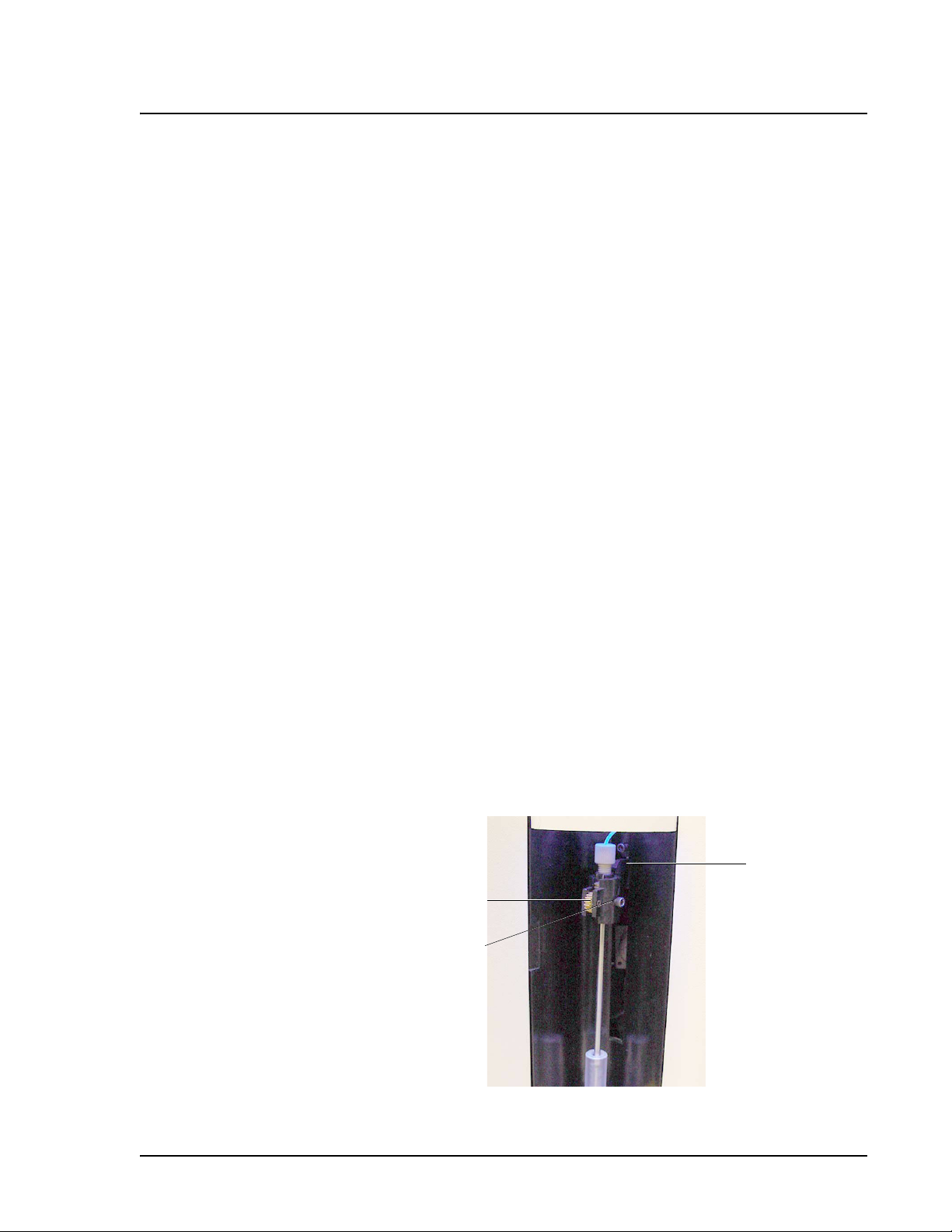
xMAP Technology Maintenance and Cleaning
11. Use a 3/32 inch hexagonal allen wrench to tighten the height
adjustment locking screw.
12. Click Test to raise the sample probe, then click OK to close the
dialog box.
13. Replace the clear plastic shield that covers the sample probe
area.
Adjusting the Sample
Probe Horizontal Position
Luminex aligns the sample probe on your Luminex 100 analyzer
prior to shipping, but you may need to adjust the horizontal position
after installing the Luminex XYP. Adjust the sample probe’s
horizontal position if it rubs or scrapes against the side of the
alignment guide. Some rubbing is acceptable, as long as the probe
movement is smooth.
Note: Improper placement of the Luminex 100 analyzer on the
Luminex XYP may cause horizontal misalignment. Verify that they
are stacked squarely before proceeding.
To adjust the horizontal position of the sample probe:
1. Turn on the Luminex XYP and the Luminex 100 analyzer. Start
the Luminex Data Collector software.
2. Use a 3/32 inch hexagonal allen wrench to loosen the arm pivot
locking screw.
3. Move the sample arm to the left or right until the sample probe is
in the center of the alignment guide.
4. Tighten the arm pivot locking screw.
The arm pivot
locking screw
Thumb
Wheel
Height
Adjustment
Locking
Screw
Figure 7-9. Sample Probe
PN 89-00002-00-063 Rev. A 7 - 11
is behind the
probe arm.
Page 92

Luminex 100 User Manual Version 1.7 xMAP Technology
Decontaminating
the Luminex 100
Analyzer for Return
Shipment
Note: If you are returning the
Luminex XYP instrument or the
Luminex SD instrument,
decontaminate accessible
surfaces using 10% bleach.
Technical Support will supply a Return Material Authorization
(RMA) number if they direct you to return the analyzer to Luminex,
and instruct you in returning the analyzer according to Luminex
procedures. Decontaminate the unit before shipping.
Before returning the Luminex 100 analyzer, sanitize and
decontaminate the accessible surfaces and internal fluidics system.
This is particularly important if you have analyzed biohazardous
samples. Make a copy of this page to complete and return with the
analyzer. Submit the completed checklist, both signed and dated,
with the Luminex 100 analyzer.
1. Replace the sheath fluid with a 10%-20% bleach solution.
2. Remove specimens, disposables, and reagents from the analyzer.
3. Sanitize the analyzer with a 10%-20% bleach solution using the
Sanitize command on the main screen of the system. Follow this
by washing twice with distilled water.
4. Turn off the power switch on the back of the analyzer, then
unplug the power cord from the wall source.
5. Disconnect the sheath fluid and waste containers.
6. Drain the sheath fluid and waste containers.
7. Rinse the waste container with a 10%-20% bleach solution.
8. Wash all exterior surfaces with a mild detergent, followed by a
10% bleach solution.
9. Open both front doors of the Luminex 100 analyzer. Clean all
accessible surfaces with mild detergent, followed by 10% bleach.
10. Pack the system in a biohazard bag. Return the unit in its original
packaging or an approved shipping container. Include a copy of
this checklist in the packaging.
Was there an internal leak in the system? Yes No
Print Name: __________________________________
Signature: ___________________________________RMA
Number: __________________ Date: ___________________
7 - 12 PN 89-00002-00-063 Rev. A
Page 93

PN 89-00002-00-063 Rev. A
Luminex 100 Maintenance Log Month(s): ________________________________________Year:_______________
Note: Follow your standard laboratory safety practices when cleaning or maintaining the system. Do not remove the analyzer cover under any circumstances.
Procedure: To use this log, fill in the month(s) and year above. This form is designed to record information for four weeks. Make photocopies as necessary. Fill in the dates for which this
log is used in line one of the table below. For each item listed at the left, add your initials under each date you perform the item.
Dates
Date/Initials: Date/Initials: Date/Initials: Date/Initials:
Date/Initials: Date/Initials: Date/Initials: Date/Initials:
Check waste level
Check sheath fluid
Tighten sheath cap
Laser warmup
Daily maintenance
Startup Initials: (for each item listed at the left, fill in your initials under each date that you perform the item)
sheath fluid)
Alcohol Flush (70% isopropano l)
Wash twice (distilled water or
Shut down Initials: (for each item listed at the left, fill in your initials under each date that you perform the item)
Sanitize (10%-20% bleach)
Soak (water)
Loosen sheath cap
Weekly
Turn the system off (optional )
Visual inspection Date/Initials: Date/Initials: Date/Initials: Date/Initials:
Monthly
Calibrate Date/Initials: Date/Initials: Date/Initials: Date/Initials:
Every six months
Replace air intake filter, analyzer Date/Initials: Date/Initials: Date/Initials: Date/Initials:
Wipe exterior surfaces Date/Initials: Date/Initials: Date/Initials: Date/Initials:
Clean sample probe Date/Initials: Date/Initials: Date/Initials: Date/Initials:
Replace air intake filter, XYP
(optional)
Replace syringe plunger seal, or
Yearly
Replace sheath filter Date/Initials: Date/Initials: Date/Initials: Date/Initials:
As required
Check analyzer ventilation filter Date/Initials: Date/Initials: Date/Initials: Date/Initials:
syringe
Replace fuses Date/Initials: Date/Initials: Date/Initials: Date/Initials:
Comments:
Page 94

Page 95

Troubleshooting
Troubleshooting procedures help users isolate, identify, and remedy
problems with the Luminex 100 analyzer and Luminex XYP
instrument. This chapter does not troubleshoot problems with the PC.
For help with PC problems, please call Dell Technical Support at
800-624-9896.
To troubleshoot a problem, start by selecting a general symptom
Next, identify the possible problem and remedy it with one of the
solutions listed.
This troubleshooting chapter supplies information for the following
topics.
• Power Supply Problems
• Communication
• Pressurization
• Fluid Leaks
• Sample Probe
• Calibration Problems
• Acquisition Problems
• Bead Detail Irregularities
• Error Messages
• Printing Errors
• Verification
You can find answers to frequently asked questions (FAQs) on the
Luminex website: http://luminexcorp.custhelp.com.
Technical assistance is available to users in the U.S. and Canada by
calling 1-877-785-BEAD (1-877-785-2323) between the hours of
7:00 a.m. and 7:00 p.m. Central Time, Monday through Friday. Users
PN 89-00002-00-063 Rev. A 8 - 1
Page 96

Luminex 100 User Manual Version 1.7 xMAP Technology
outside of the U.S. and Canada can call us at +1 512-381-4397
between the hours of 7:00 a.m. and 7:00 p.m. Central Time, Monday
through Friday. You may send inquiries by email to
support@luminexcorp.com. You can also read answers to common
troubleshooting questions at http://luminexcorp.custhelp.com.
Power Supply
Problems
Symptom Possible problem Solution
Analyzer will not turn on, or
XYP will not turn on.
Fuses continue to open (blow). A component has a short circuit. Contact Technical Support.
Power supply problems often involve a blown fuse, faulty electronic
component, or even something as simple as a disconnected cable.
Use extreme care when you replace a fuse.
The power cord is disconnected. Verify that the power cord is
Plugged in.
No voltage is coming from the
electrical outlet.
The power supply is faulty. Contact Technical Support.
A fuse has burned out. See page 7-8 for instructions on
Verify that the electrical outlet is
operational.
changing fuses.
Communication The communication problems described in this section involve the
links between the data system (PC and Luminex Data Collector
software) and the Luminex 100 analyzer and XYP instrument. This
section does not address communication issues with other peripheral
devices.
The term “Communication” refers to:
• The transfer of data between the PC and the analyzer.
• The current status of the analyzer and XYP instrument.
• Instrument readbacks.
• Instrument control, sample acquisition, session uploading, and
start, stop and pause features.
Symptom Possible Problem Solution
PC cannot initialize
communication with analyzer.
8 - 2 PN 89-00002-00-063 Rev. A
The communications cable is
unplugged.
Check the communications
cable connections.
Page 97

xMAP Technology Troubleshooting
“Bad Link” error message There is a bad link between the
PC, analyzer, and/or XYP.
The Machine Setup is using the
wrong COM Port.
XY Platform microtiter plate
connect error. Command
timed out.
There is a bad link between the
XYP and PC.
Ensure that the instruments have
power.
Check the power cord and
communication cable
connections
Shut down the PC and analyzer.
Turn on the analyzer before
turning on the PC.
On the Analyzer menu, click
Setup. Verify that the correct
ports are selected for each
instrument. If you have make
changes, restart the system.
Ensure that the communication
cable between the PC and XYP
is connected.
Pressurization Normal air and sheath pressure readings vary between 6-9 psi while
the compressor runs. If the system pressure is out of range, your
sample acquisition will fail or return poor results.
Symptom Possible Problem Solution
Pressurization Fails or
Pressure too low.
The sheath and waste lines are
not fully connected.
An air leak is present in the
sheath bottle.
The sheath or waste bottle
fittings are cracked.
There is a leak in the system. Check for system leaks.
The compressor does not
engage.
The Cheminert Fitting is loose. Ensure that the fitting connects
Fluid leaks in the system. See Fluid Leak on page 8-4.
Make sure the lines between the
sheath and waste bottles and the
analyzer are fully connected.
Remove and retighten the
sheath bottle cap.
Inspect the fittings to be sure
they form a tight seal.
Run a Prime command. If you
do not hear the compressor turn
on, call Technical Support.
tightly above the sample probe,
below the blue light.
PN 89-00002-00-063 Rev. A 8 - 3
Page 98

Luminex 100 User Manual Version 1.7 xMAP Technology
The sheath bottle has an air
leak.
Pressure too High The sheath bottle is overfilled. Ensure that the sheath bottle is
Disconnect the sheath and waste
bottle connections from the
analyzer. Run a Prime
command. If pressure builds,
remove and retighten the sheath
fluid bottle cap, then reconnect
fluid lines to the analyzer. If
pressurization fails again,
replace the sheath bottle.
not filled above the fill line.
Fluid Leaks Fluid leaks can result in poor pressurization and failed sample
acquisition.
Symptom Possible Problem Solution
Pressure too low The sample probe is clogged. Clean the sample probe. See
page 7-4.
Large amount of fluid pooled
around instrument
Fluid coming from sample
probe
Fluid leaking from front of
analyzer
The syringe seal leaks. Replace the syringe seal. See
page 7-6.
The syringe valve leaks. Hand-tighten the syringe
connection (silver knob) on the
syringe valve. Run a Prime
command. If leaks continue, call
Technical Support.
Fittings or fluid lines are
damaged.
The sample probe is clogged. Clean the sample probe. See
The sample 3-way valve is
faulty.
The syringe seal leaks. Replace the syringe seal.
The syringe valve leaks. Hand-tighten the syringe
Contact Technical Support.
page 7-4.
Contact Technical Support.
connection (silver knob) to the
white syringe valve. Run a
Prime. If leaks continue, contact
Technical Support.
8 - 4 PN 89-00002-00-063 Rev. A
Page 99

xMAP Technology Troubleshooting
Sample Probe Problems with the sample probe can lead to fluid leaks and
pressurization problems, as well as inhibit sample acquisition.
Symptom Possible Problem Solution
Sample probe leak The sample probe is clogged. Clean the sample probe. See
page 7-4.
Sample arm stuck in the up
position
Sample arm stuck in the down
position
The system isn’t properly
pressurized.
The sample probe height is too
low, or the path to the well is
blocked.
If a PRESSURIZATION error
message displays, see
Pressurization on page 8-3.
DO NOT turn off Luminex XYP
instrument.
1. Remove the blue light housing
on the Luminex 100 analyzer.
2. Unscrew the tubing connector
connecting the sample tube to
the top of the sample arm.
The system monitor changes
from “Busy” to “Running”
and sample acquisition
continues. Click Cancel to
make adjustments before
continuing with the rest of the
samples.
3. If sample arm still does not
raise, save all the data that has
been collected to this point.
Turn off the analyzer, but
LEAVE THE XYP instrument
turned on.
4. Exit Data Collector.
5. Turn the analyzer back on and
restart the software.
6. Replace the sample tubing
and blue light. Adjust the
sample arm.
7. Run a calibration with water
to reset the sample probe
optical switch.
PN 89-00002-00-063 Rev. A 8 - 5
Page 100

Luminex 100 User Manual Version 1.7 xMAP Technology
Sample arm does not go down
smoothly.
The 96-well plate is incorrectly
seated in the XYP.
The 96-well plate is warped. Inspect the 96-well plate. Replace
The sample arm is misaligned. Readjust the sample arm
The analyzer is misaligned with
the XYP instrument.
The sample probe is bent. Remove the sample probe from
Adjust the 96-well plate.
it if it is warped.
horizontal alignment.
Reposition the Luminex 100
analyzer on top of the Luminex
XYP instrument so that the holes
match up correctly. The
alignment guide should tighten
and loosen fairly easily if the
instruments are aligned correctly.
Continue to square the
instruments until the guide
loosens and tightens easily.
the Luminex 100 analyzer. Roll it
on a flat surface. If it does not roll
smoothly, replace it with a new
sample probe.
Calibration
Problems
Calibration is slow or fails There is a bad link between the
PC and the analyzer.
The calibration microspheres
are not fully suspended.
Wrong calibration lot chosen in
the Calibration Setup window.
Verify that all instruments
turned on and all
communications cables are in
place on back of instruments.
Vortex the calibration vials to
resuspend the microspheres.
In the Main Window of the
Luminex Data Collector
software, click Calibrate. In the
Start Calibration dialog box,
make sure that the correct lot
numbers are shown in both the
Classification Channel and
Reporter Channel menus.
8 - 6 PN 89-00002-00-063 Rev. A
 Loading...