


Ridgegate
FF
A
G
3CCT
Bulkhead
IP65
3CCT
INSTALLATION INSTRUCTIONS
BESA
100^
Lm/W
14W
3 YR
Warranty
Ridgegate
READ THESE INSTRUCTIONS
THOROUGHLY BEFORE
INSTALLATION KEEP THESE
INSTRUCTIONS FOR
FUTURE REFERENCE.
IMPORTANT:
This product must be installed
by a qualifi ed electrician or
competent person, and in
accordance with current building
and IET wiring regulations.
BOX CONTENTS
This lighting xture has been properly
packed to avoid damage during
transit. Before commencing with the
installation carefully inspect the
luminaire to con rm there is no
damage. DO NOT INSTALL if any
damage has occurred to the xture
or any of its components.
• Light Fitting
• Instruction Manual
• Fixing Kit
TOOLS REQUIRED
• Drill
• Screwdriver
• Cable
1 2
on
off
4
Grommet
5
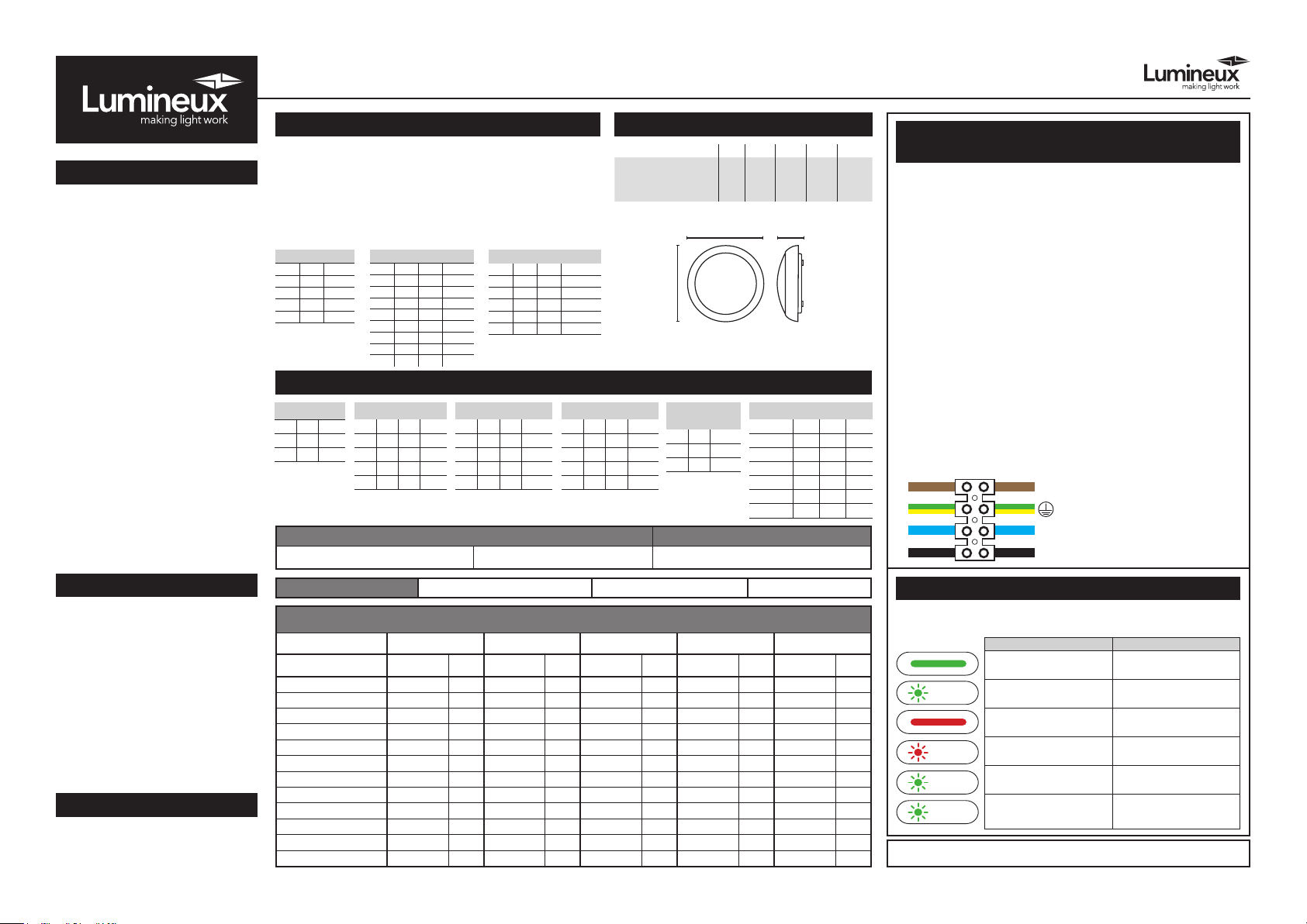
Electrical connection wiring
Twist-lock
Geartray
NEUTRAL = Blue
EARTH = Green/Yellow
LIVE (SW) = Brown
3
6
on
off
Bulkhead
PLEASE READ THESE INSTRUCTIONS
BEFORE INSTALLATION.
WARNING: Risk of electric shock! Isolate
the mains power before proceeding.
• Turn off the mains power before performing
inspections, installation, or removal
• Verify that the supply voltage is correct by
comparing it with the luminaire label information
• It is the installers responsibility to ensure installation
is suitable for the total load of the luminaire(s). The
supply cable, fuses/circuit brakers must be correctly
rated for the electrical load and considering for any
transient inrush currents that may occur
• Do not perform insulation strength or resistance
tests on installed luminarie(s) connected
1. Remove the diffuser by gently twisting anti-clockwise
2. Twist the locking tabs to loosen and remove the
geartray
3. Drill appropriately sized holes through your chosen
mounting points in the base
4. Install grommet to your chosen cable entry and pierce,
making a hole just large enough to make a tight t
around the incoming mains cable. Carefully thread
cable through grommet
5. Secure the tting in place. Note: If protection against
ingress of moisture is required the heads of screws
must be covered with a silicone or similar sealant
6. Wire as per diagram (5)
7. Please see overleaf for instructions on how to set
all sensor versions
8. Replace the geartray and twist the locking tab to
secure in place, then re t the diffuser
9. Re-connect the mains supply
Manby Business Park, Manby, Lincolnshire, LN11 8UT
Lumineux is a B&T Associates Ltd company.
Technical Helpline: +44 (0)1507 328031
^Lm/W gures based on 4000K output.
www.lumineux.co.uk
1 Sec ON
1 Sec OFF
3 Sec ON
3 Sec OFF
3 Sec ON
1 Sec OFF
0.5 Sec ON
0.5 Sec OFF
Ridgegate 3CCT Bulkhead
DISPOSAL
Disassembly instructions for end of
life disposal available on website.
Disposal of Electronic Equipment
WEEE Directive 2002/96/EC This
product falls within the scope of
the Waste Electrical & Electronic
Equipment Directive (WEEE), which
means the product should not be
disposed of as normal household
waste. Please recycle where
facilities exist or check with your
Local Authority. RoHS – All
components and materials used in
this product are RoHS 2002/95/EC
compliant.
Specications may change from time
to time. The information contained
in this leaet is for guidance only
and should not be considered as
always accurate and should be
treated as not representative.
MICROWAVE SENSOR SETTINGS
Detection Range: This determines the effective range of the motion.
Note that reducing the sensitivity will also narrow the detection range.
Hold Time Duration: This determines the time the tting remains at
100% illumination following motion detection.
RIDGEGATE BULKHEAD DIMENSIONS
Part No. Description Watts L (mm) W (mm) H (mm) Weight
430155
Ridgegate
3CCT
Bulkhead
320 320 85
14W
Daylight Setting: This setting holds off the 100% light output should
there be sufcient daylight.
STANDARD ON/OFF SENSOR
DETECTION AREA
1 2
ON ON 100%
ON - 75%
- ON 50%
- - 25%
3 4 5
ON ON ON 5S
ON ON - 30S
ON - ON 1Min
ON - - 3Min
- ON ON 5Min
- ON - 10Min
- - ON 20Min
- - - 30Min
HOLD TIME
DAYLIGHT
6 7 8
ON ON ON 2Lux
ON ON - 10Lux
- ON - 25Lux
ON - - 50Lux
- - - Disable
L
W H
STEP DIM DRIVER SETTINGS
DETECTION AREA
1
I ON 100%
II - 50%
HOLD TIME
2 3
I ON ON 5S
II ON - 90S
III - ON 3min
IV - - 10min
DAYLIGHT SENSOR
4 5
I ON ON Disable
II ON - 30 Lux
III - ON 15 Lux
IV - - 5 Lux
* Do not change output current unless instructed or this will void warranty.
STAND-BY PERIOD
6 7
I ON ON 0s
II ON - 30s
III - ON 10min
IV - - +∞
STAND-BY
DIM LEVEL
8
I ON 10%
II _ 25%
* OUTPUT CURRENT
S1 S2 S3
450mA ON ON ON
400mA ON - ON
380mA - - ON
350mA - ON 320mA ON - 300mA - - -
Installation Engineers Contact Details: Luminaire Reference / Location
Name:
Tel:
0.98Kg
Wiring instructions for units equipped
an with EMERGENCY function
Emergency lighting luminaries must be installed and maintained in
accordance with the emergency lighting standard BS 5266-1
1. Connect incoming earth cable to ‘Earth’ terminal on connector block.
2. Connect incoming neutral cable to ‘Neutral’ terminal on connector block.
3. For the emergency unit to work correctly, please ensure that an
uninterrupted permanent live feed is present and is connected directly
to the ‘Permanent Live’ terminal of the mains terminal block. Please
ensure there are no switches, PIRs etc within the permanent live feed,
constant switching of the emergency pack could result in premature
battery failure.
4. Connect incoming switched live cable to the terminal marked
“Switched Live”
NOTE: If there is no switch live feed and the unit has a microwave sensor,
simply bridge across from the “Permanent Live” to the Switch Live” on the
mains terminal block.
5. There should be a loose ying lead connected to the battery. This needs
to be attached to the ying lead from the emergency control unit.
6. Following power up the green LED indicator should illuminate to indicate
charging. If power to the unit is disrupted or isolated, the unit indicating
green LED will switch off, triggering the emergency LEDs to illuminate.
7. Please allow 24 hours charge before rst emergency test.
EMERGENCY FITTINGS ONLY. EARTH CONNECTION REQUIRED.
L - LIVE (SW) = Brown
- EARTH = Green/Yellow
N - NEUTRAL = Blue
L1 - PERMANENT LIVE (PL) = Black
WARRANTY
This luminaire is warranted for a
period of 3 years from the date of
purchase**. The backup battery
pack in the emergency version
is warranted for a period of 12
months. The warranty could be
invalidated should the light tting
not be installed according to these
instructions, outside the scope of
the specication or the product
has been altered or tampered with
in any way. Please see website for
terms and conditions.
PRODUCT TEMP SPECIFICATION
Standard -20 to +40ºC
Emergency 0 to +30ºC
Revision 2 - JULY 2022 Rev.
Luminaire Details: Full Recharge Duration 24 Hours Emergency Duration 3 Hours Lamp Type LED
ROUTINE TEST RECORD
Type Test
Signed Date Signed Date Signed Date Signed Date Signed Date
Functional 1
Functional 2
Functional 3
Functional 4
Functional 5
Functional 6
Functional 7
Functional 8
Functional 9
Functional 10
Functional 11
3hr Duration 12
** Please see our website for more detailed information on warranty.
Year 1 Year 2 Year 3 Year 4 Year 5
Self-Test EMERGENCY function
The self-test version of emergency is tted with control gear that will carry out
periodic functional tests every 1 month and full duration test every 12 months.
Fault/Test/Status Reason
Battery fully charged
and operational
Battery Charging
Battery Failure
Duration Test Failure
Automatic Testing - Function
5 minute test (Every 30 days)
Automatic Testing -
Duration test is 3 hours
(every 12 months)
Standard daily use
Initial charge /
battery topping up
Battery is disconnected or
damaged/faulty
Maintenance check required
by qualied engineer
Self-testing in
operation
Self-testing in
operation
This product contains a light source of energy efciency Class F.
Technical Helpline: +44 (0)1507 328031
 Loading...