

Page 1

Stellaris® Serial-to-Ethernet
Reference Design Kit
USER’S MANUAL
RDK-S2E-02 Copyright © 2008 Luminary Micro, Inc.
Page 2

Legal Disclaimers and Trademark Information
INFORMATION IN THIS DOCUMENT IS PROVIDED IN CONNECTION WITH LUMINARY MICRO PRODUCTS. NO LICENSE,
EXPRESS OR IMPLIED, BY ESTOPPEL OR OTHERWISE, TO ANY INTELLECTUAL PROPERTY RIGHTS IS GRANTED BY THIS
DOCUMENT. EXCEPT AS PROVIDED IN LUMINARY MICRO’S TERMS AND CONDITIONS OF SALE FOR SUCH PRODUCTS,
LUMINARY MICRO ASSUMES NO LIABILITY WHATSOEVER, AND LUMINARY MICRO DISCLAIMS ANY EXPRESS OR IMPLIED
WARRANTY, RELATING TO SALE AND/OR USE OF LUMINARY MICRO’S PRODUCTS INCLUD ING LIABILITY OR WARRANTIES
RELATING TO FITNESS FOR A PARTICULAR PURPOSE, MERCHANTABILITY, OR INFRINGEMENT OF ANY PATENT, COPYRIGHT
OR OTHER INTELLECTUAL PROPERTY RIGHT. LUMINARY MICRO’S PRODUCTS ARE NOT INTENDED FOR USE IN MEDICAL,
LIFE SAVING, OR LIFE-SUSTAINING APPLICATIONS.
Luminary Micro may make changes to specifications and product descriptions at any time, without notice. Contact your local Luminary Micro
sales office or your distributor to obtain the latest specifications before placing your product order.
Designers must not rely on the absence or characteristics of any features or instructions marked “reserved” or “undefined.” Luminary Micro
reserves these for future definition and shall have no responsibility whatsoever for conflicts or incompatibilities arising from future changes to
them.
Copyright © 2008 Luminary Micro, Inc. All rights reserved. Stellaris, Luminary Micro, and the Luminary Micro logo are registered trademarks of
Luminary Micro, Inc. or its subsidiaries in the United States and other countries. ARM and Thumb are registered trademarks, and Cortex is a
trademark of ARM Limited. Other names and brands may be claimed as the property of others.
Luminary Micro, Inc.
108 Wild Basin, Suite 350
Austin, TX 78746
Main: +1-512-279-8800
Fax: +1-512-279-8879
http://www.luminarymicro.com
2 November 4, 2008
Page 3

Stellaris® S2E RDK User’s Manual
Table of Contents
Chapter 1: Stellaris® Serial-to-Ethernet Reference Design Kit Overview...................................................7
Using the RDK....................................................................................................................................................7
Features..............................................................................................................................................................8
Kit Contents.................. ... ... .... ... ... ... .... .......................................... ..................................................................... 8
Description..........................................................................................................................................................8
Serial-to-Ethernet Module............................................................................................................................... 8
Serial-to-Ethernet Connector Board................................................................................................................9
Flow Control...................................................... .......................................... ... ...................................................10
Installation.........................................................................................................................................................10
Specifications....................................................................................................................................................11
Electrical .......................................................................................................................................................11
Mechanical....................................................................................................................................................11
Chapter 2: Serial-to-Ethernet Configuration and Firmware Update........................................................... 13
Accessing the Configuration Website...............................................................................................................13
Using “My Network Places”...........................................................................................................................13
Using the LM S2E Browser Application........................................................................................................14
Home Page...................................................................................................................................................14
Port 0 and Port 1 Settings Pages ........................ ... ... ... .... ... ... ... .... .......................................... .........................15
Miscellaneous Settings Page............................................................................................................................ 17
Firmware Update Page.....................................................................................................................................18
Chapter 3: Using the S2E Module as a Serial Extender over Ethernet......................................................21
Chapter 4: Using Serial-to-Ethernet as a Virtual COM Port........................................................................23
Overview...........................................................................................................................................................23
Install com0com................................................................................................................................................ 23
Install com2tcp.................................................................................................................................................. 28
Install LM PC S2E Configuration ......................................................................................................................28
Configure VCP Using the LM S2E PC Configuration Application.....................................................................29
Connection creation........ .... ... ... ... .... ... .......................................... ... ... .... ... ... ... ... .... ...................................... 30
Edit port names.............................................................................................................................................32
Manual VCP Configuration ............................................................................................................................... 32
Verify VCP Operation .......................................................................................................................................33
Chapter 5: Hardware Description..................................................................................................................35
Block Diagram .................................................................................................................................................. 35
Appendix A: Schematics................................................................................................................................ 37
Appendix B: Bill of Materials (BOM) ............................................................................................................. 39
Appendix C: Contact Information .................................................................................................................41
November 4, 2008 3
Page 4

List of Figures
Figure 1-1. Serial-to-Ethernet Module and S2E Connector Board ....................................................................7
Figure 1-2. Serial-to-Ethernet Module ...............................................................................................................9
Figure 1-3. Serial-to-Ethernet Connector Board................................................................................................9
Figure 1-4. S2E Module Connection to S2E-CKIT ..........................................................................................11
Figure 2-1. LM S2E Browser Window.................... ... ... .... ... ... ... .............................................. ... ... ... ................14
Figure 2-2. Home Page of the Configuration Website............................... ... ... ... ............................................. 15
Figure 2-3. Port 0 Configuration Window.................. ... .... ... ... ... .... ... ... ... .... ... ... ... ... .... ... ... ... .... ... ... ... ................17
Figure 2-4. Miscellaneous Settings Page ........................................................................................................18
Figure 3-1. Implementing a Serial Extender over Ethernet..............................................................................21
Figure 4-1. Typical S2E Module ................................. .... ... .......................................... ... ... .... ... ......................23
Figure 4-2. Luminary Micro menu group..........................................................................................................29
Figure 4-3. S2E module connection over Ethernet..........................................................................................30
Figure 4-4. Main LM S2E Configuration application window ...........................................................................31
Figure 4-5. Manual VCP configuration.............................................................................................................33
Figure 4-6. Com2tcp communication shown in the command prompt window................................................33
Figure 4-7. HyperTerminal File Properties Dialog ...........................................................................................34
Figure 5-1. Serial-to-Ethernet Block Diagram.................................................................................................. 35
4 November 4, 2008
Page 5

Stellaris® S2E RDK User’s Manual
List of Tables
Table 1-1. J2 Header Signals.........................................................................................................................10
Table 1-2. J3 Header Signals.........................................................................................................................10
Table B-1. Serial-to-Ethernet Bill-of-Materials ................................................................................................ 39
Table B-2. Serial-to-Ethernet Connector Board Bill-of-Materials ....................................................................40
November 4, 2008 5
Page 6

6 November 4, 2008
Page 7
Front
Back
CHAPTER 1
Stellaris® Serial-to-Ethernet Reference Design Kit
Overview
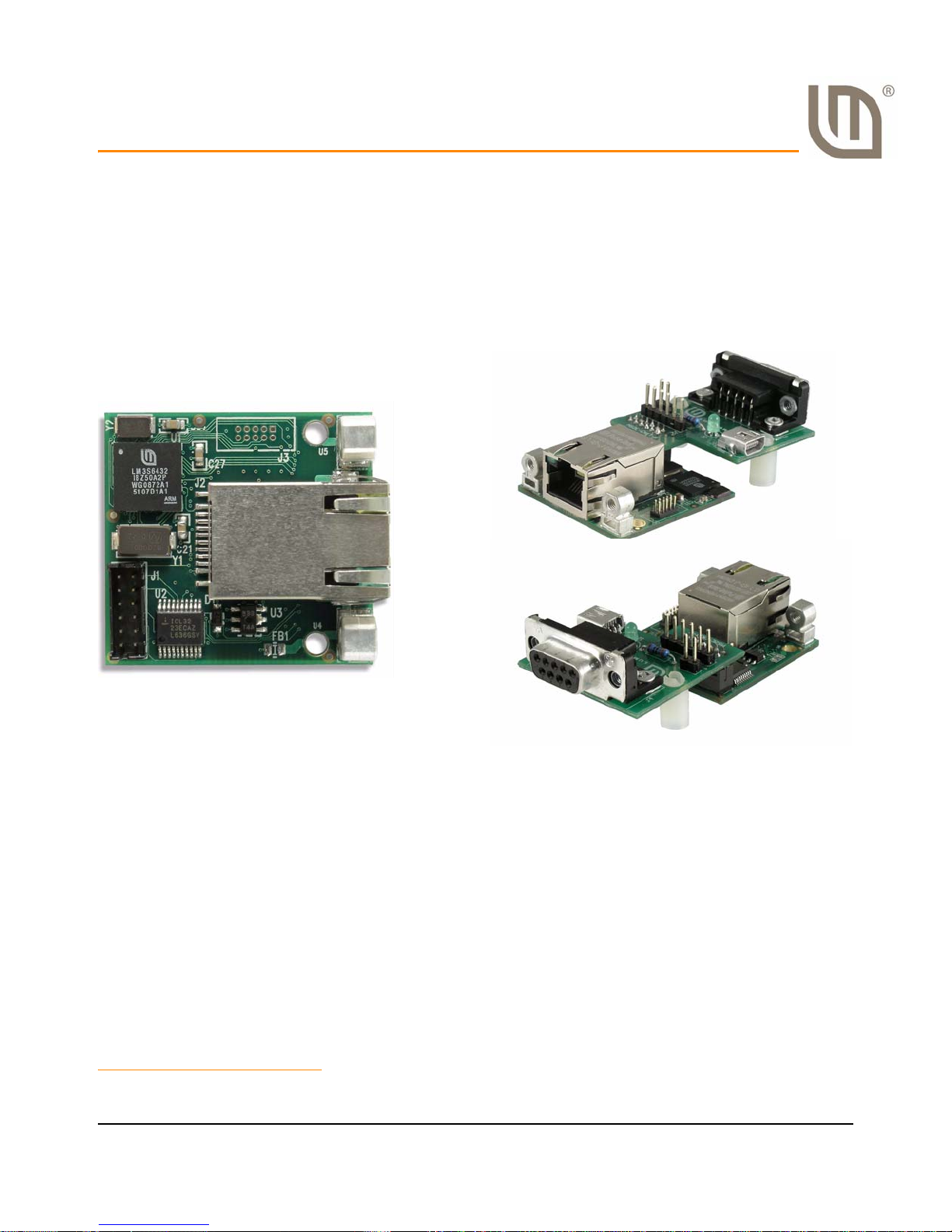
Reference Design Kits (RDKs) from Luminary Micro accelerate product development by pro vi ding
ready-to-run hardware. This kit includes all the necessary cables, S2E connector board, and
software to run a demo application out of the box.
Figure 1-1. Serial-to-Ethernet Module and S2E Connector Board
Using the RDK
The recommended steps for using the RDK ar e:
1
Follow the Quickstart Guide included in the kit.
The Quickstart guide will help you get the S2E module up and running in minutes. It also
contains important safety information that should be read before using the RDK.
Follow the appropriate chapters in this document to configure the S2E module for a
specific application.
If required, customize the S2E module hardware and software. Luminary Micro provides
full source code and design files.
1. Images are not shown to scale.
November 4, 2008 7
Page 8

Stellaris® Serial-to-Ethernet Reference Design Kit Overview
Features
The S2E module is intended as a simple add-on product to existing systems to provide network
connectivity. The RDK contains all the necessary hardware to quickly evaluate the module
capabilities. The S2E module RDK has the following features:
LM3S6432 Stellaris microcontroller with 96 kB of Flash memory and 32 kB of SRAM
10/100 Mbit Ethernet port
Two serial ports
– PORT0 is an asynchronous serial port with RS232 levels
• Data rates up to 230,400 bits/sec
• Includes RTS/CTS for flow control
– PORT1 has 4 CMOS/TTL level signals that can be configured several ways
• Data rates up to 1 Mbit/sec.
• As an asynchronous serial port with RTS/CTS flow control or with 2 GPIOs
• As 4 GPIOs
• As a synchronous serial port (master or slave) with support for SPI, uWire , and other
synchronous protocols
RDK is USB-powered, no additional power supply required
Ethernet boot loader for firmware upgrades
JTAG 10-pin debug header
Kit Contents
S2E Module: Serial-to-Ethernet module
S2E-CKIT: Serial-to-Ethernet connector board
USB A to miniB cable: For powering the module
Serial cable DB9M - DB9F: For connecting module to PC serial port
Ethernet retractable cable: For connecting S2E module to the network
20-pin to fine-pitch 10-pin ARM JTAG debug adapter
S2E-CKIT standoffs: For optional attachment to S2E-CKIT board
Description
Serial-to-Ethernet Module
Figure 1-2 shows the S2E module diagram. The S2E header connector provides the serial port
signals and power signals to the module. For the RDK, th is is connected to the S2E-CKIT (see
Figure 1-3). For more information on the S2E module, see the Serial-to-Ethernet board data sheet.
8 November 4, 2008
Page 9
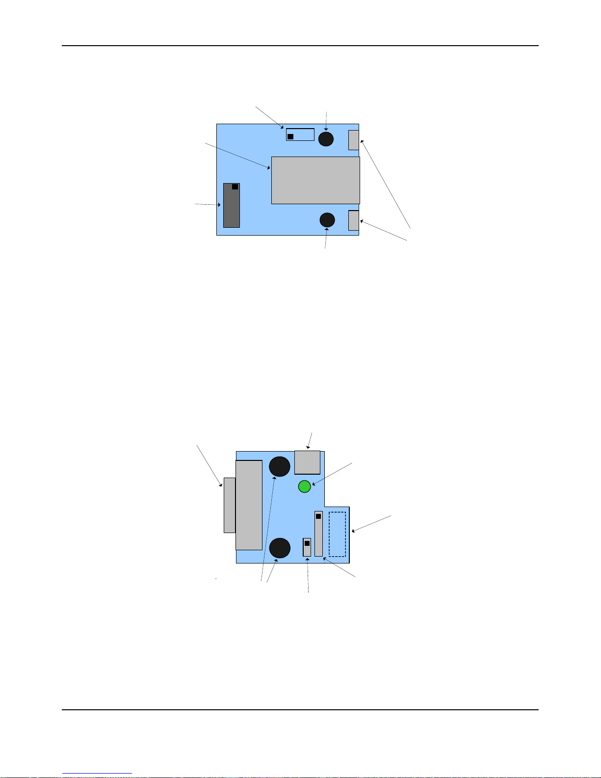
Figure 1-2. Serial-to-Ethernet Module
RJ45
J1
Network
Connector
Faceplate
Spacers
(M3 thread)
Mounting
Hole
Mounting
Hole
S2E Header
Connector
JTAG Header
Pads
USB
DB9F
J1
J2
J3
D1
USB Power
Connector
PORT0
Connector
S2E Socket
Connector
(Bottom side)
PORT1 Header
3.3V Header
Power
Indicator
Standoff
Holes
Serial-to-Ethernet Connector Board
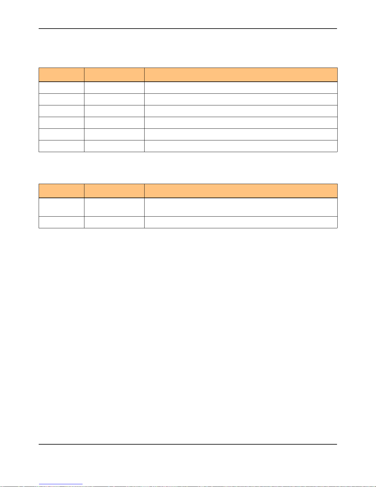
Figure 1-3 shows the Serial-to-Ethernet connector board. The board connects to the S2E module
via the J1 connector, and provides connectors for power and serial port connections during RDK
evaluation and development. Power can be provided by the USB connector (5 V) or by the J3
header (3.3 V). A power indicator LED turns on when power is applied. Header J2 provides the
CMOS/TTL signals for the module Port1 signals, see Table 1-1. The J3 header signals are shown
in Table 1-2.
Stellaris® S2E RDK User’s Manual
Figure 1-3. Serial-to-Ethernet Connector Board
November 4, 2008 9
Page 10
Stellaris® Serial-to-Ethernet Reference Design Kit Overview
Table 1-1. J2 Header Signals
J2 Header Pin Stellaris GPIO Description
1 PD2/PA4 Serial data input to S2E module (UART or SPI)
2 PD3/PA5 Serial data output from S2E module (UART or SPI)
3 PA3 UART CTS output or SPI select signal
4 P A2 UART RTS input or SPI clock signal
5 RSTn Reset input to S2E module (leave unconnected if unused)
6 GND Ground signal
Table 1-2. J3 Header Signals
J3 Header Pin Signal Description
3.3 V 3.3 V 3.3 V po wer input. Use only if the USB power connector is not used, otherwise leave unconnected.
GND GND Ground signal
Flow Control
The S2E module supports bidirectional RTS/CTS flow control, as defined in the RS-232 E
standard.
For the receiver, in this mode of ope ration, the S2E asserts the CTS signal when it capable of
receiving data, and it deasserts the signal when transmission by the remote serial device should
be paused. In the S2E module, the CTS signal is asserted by setting the CTS output GPIO for the
0 (or low) level. The signal is deasserted by setting the GPIO output value to the 1 (or high) level.
For the transmitter, the RTS GPIO signal is monitored for state changes. When the state changes
to asserted, transmission is allowed/resumed. When the state changes to deasserted,
transmission is paused. The polarity of the RTS GPIO signal is interpreted in the same way as for
the CTS GPIO signal. If the RTS GPIO signal is 1 (or high level), it is considered to be deasserted,
and the UART transmitter is disabled (the current byte, if any, is completed). When the signal is 0
or low level), it is considered to be asserted, and the transmitter is re-enabled.
Installation
The requirements for installation include a PC with an available serial port with a DB9 male
connector and a USB port, and an available 10/100Mbit network port. The S2E-CKIT board
contains the connectors required for powering and connecting the module, and sits on top of the
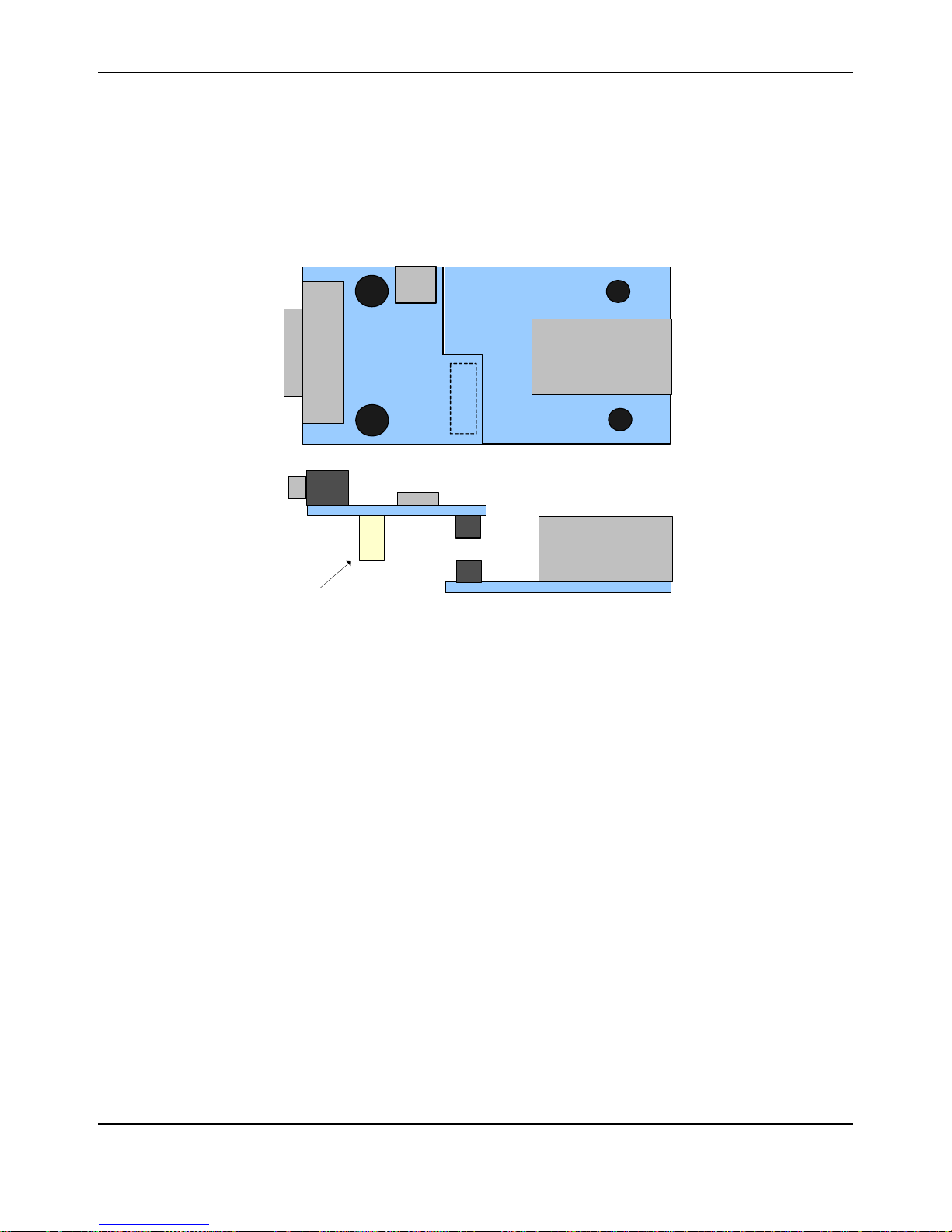
S2E module. Use the following steps to connect the S2E module to the S2E-CKIT connector board
(see Figure 1-4).
1. Attach the provided nylon standoffs to S2E-CKIT (optional).
2. Attach S2E-CKIT to the S2E module. Align the 12-pin socket to the 12-pin connector on the
S2E module and press firmly.
10 November 4, 2008
Page 11
Stellaris® S2E RDK User’s Manual
RJ45
USB
DB9F
J1
Optional
Standoffs
3. Connect the serial cable: DB9M (male) side to the DB9F(female) connector on the S2E-CKIT
and DB9F side to the serial port on the PC.
4. Connect the USB cable MiniAB plug to the S2E-CKIT and the other side to the PC. The green
LED on the S2E-CKIT should turn on, indicating that the S2E module is now powered.
5. Connect the ethernet retractable cable to the S2E module and to a network port.
Figure 1-4. S2E Module Connection to S2E-CKIT
Specifications
Electrical
USB power: 5V at 200mA
Mechanical
S2E module PCB size: 1.475 x 1.555" x 0.63” (39.5 mm x 37.5 mm x 16 mm)
S2E-CKIT PCB size: 1.475 x 1.5" x 0.57” (39.5 mm x 38.1 mm x 14.5 mm)
November 4, 2008 11
Page 12

Stellaris® Serial-to-Ethernet Reference Design Kit Overview
12 November 4, 2008
Page 13

CHAPTER 2
Serial-to-Ethernet Configuration and Firmware
Update
The sotware in the S2E module includes an embedded web server that provides a convenient
configuration interface.
Accessing the Configuration Website
You can access the S2E module’s web-based configuration interface:
Using “My Network Places”
Using the LM S2E Browser Application
Using “My Network Places”
To access the configuration website without us in g the S2E configuration application, Windows
must first be configured to show icons for networked UPnP devices. To do this in Windows XP,
follow these steps:
1. Click Start, and then click Control Panel. Click Add or Remove Programs.
2. Click Add/Remove Windows Components.
3. In the Components list, click to select the Networking Services check box, and then click
Details.
4. In the Subcomponents of Networking Services list, click to select UPnP User Interface
check box and then click OK.
NOTE: To remove the UPnP UI components, click to clear the UPnP User Interface check box.
5. In the Windows Components Wizard, click Next.
For more information on Windows and UPnP, visit the Microsoft Help and Support website at http:/
/support.microsoft.com/.
To find the UPnP icon for the S2E module, follow these steps:
1. Go to “My Network Places”. “My Network Places” can typically be found by simply clicking
Start and then My Network Places.
2. Look for a UPnP icon labeled “Luminary Micro Serial2Ethernet Module”. The label should also
include the IP address of the S2E module.
Double-clicking on the icon will bring up the configuration website served up by the S2E module in
a web browser.
November 4, 2008 13
Page 14
Serial-to-Ethernet Configuration and Firmware Update
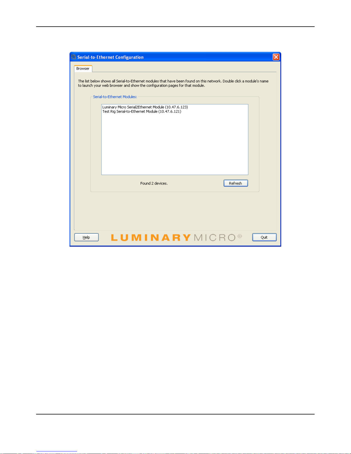
Figure 2-1. LM S2E Browser Window
NOTE: If the “Luminary Micro Serial2Ethernet Module” UPnP icon is not present, ensure that you
have configured Windows appropriately to show icons for networked UPnP devices.
Using the LM S2E Browser Application
If you installed the S2E configuration applications, to access the module configuration website:
1. Click Start, and then select All Programs > Luminary Micro > Serial-to-Ethernet
Configuration > LM S2E Browser.
2. The application shows a list of all the S2E modules on your network. If “Searching for
devices...” appears below the list, wait a few seconds for the list to populate.
3. Double-click the desired module. Your default web browser launches and loads the selected
configuration website.
Home Page
The home page of the configuration website shows the current status and configuration
information. Included are the name, IP address, and MAC address of the S2E module as well as
the current port settings for both port 0 and port 1. Figure 2-2 shows the home page of the website
hosted by the S2E module.
14 November 4, 2008
Page 15
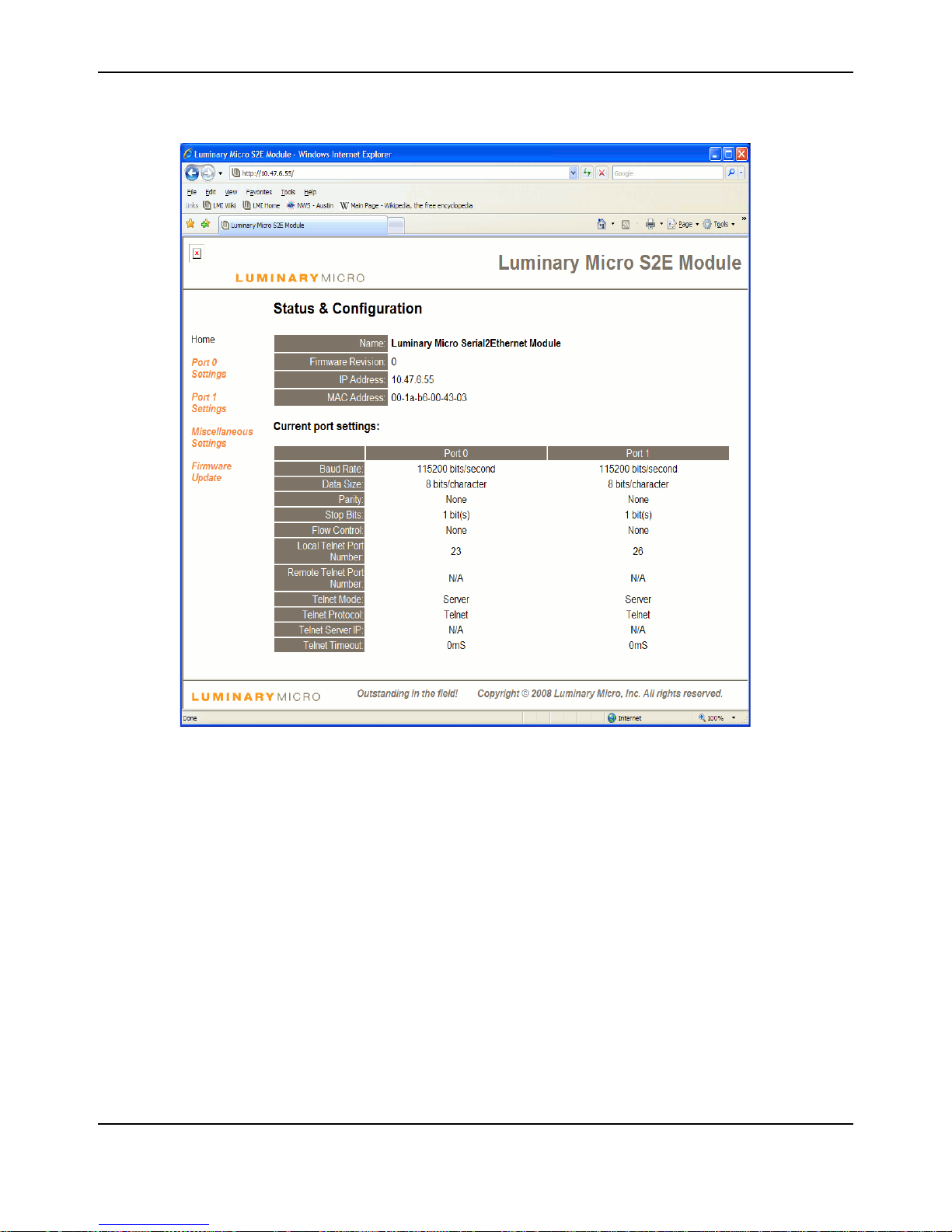
Figure 2-2. Home Page of the Configuration Website
Stellaris® S2E RDK User’s Manual
Port 0 and Port 1 Settings Pages
The “Port 0 Settings” page allows configuration of port 0 of the S2E module. Similarly, the “Port 1
Settings” page allows configuration of port 1 of the S2E module. The following configuration
options are provided:
Baud Rate – specifies the baud rate to be used by the serial port. There are several options
from 110 to 230400 bits/S.
Data Size – configures the number of data bits per character. The options are 5 to 8 bits /
character.
Parity – specifies the generation and checking of the parity bit in the data frame and the type of
parity used. The options are “None”, “Odd”, “Even”, “Mark”, and “Space”.
Stop Bits – specifies the number of stop bits at the end of a frame.
Flow Control – specifies the use of flow control. The options are “None” and “Hardware”.
Local Telnet Port Number – specifies the local telnet port number to be used.
November 4, 2008 15
Page 16

Serial-to-Ethernet Configuration and Firmware Update
Remote Telnet Port Number – specifies the remote telnet port number to be used when the
“Telnet Mode” is set to “Client”.
Telnet Mode – specifies whether the telnet mode for that port will be “Server” or “Client”.
Telnet Protocol – specifies whether the data for the port will be “Telnet” or “Raw”.
Telnet Server IP – specifies the IP address of th e telnet server when the “Telnet Mode” is set to
“Client”.
Telnet T imeout – specifies the telnet timeout in seconds. The default is 0 and specifies that no
timeout is to be used.
After changing the settings, click the “Apply Changes” button to cause the changes to take effect.
If the “Make these the default settings” chec k box is checked before clicking the “Apply Changes”
button, then the new settings are applied each time the S2E module is reset. Otherwise, the
existing defaults are used whenever the module is next reset. Figure 2-3 shows the configuration
page for Port 0.
16 November 4, 2008
Page 17
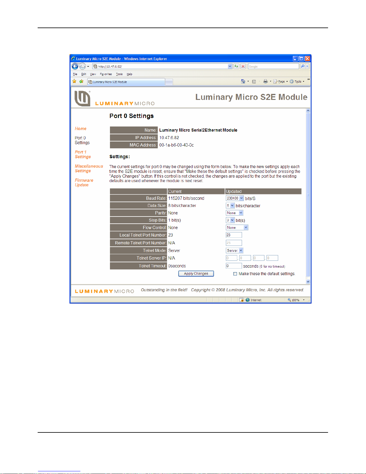
Figure 2-3. Port 0 Configuration Window
Stellaris® S2E RDK User’s Manual
Miscellaneous Settings Page
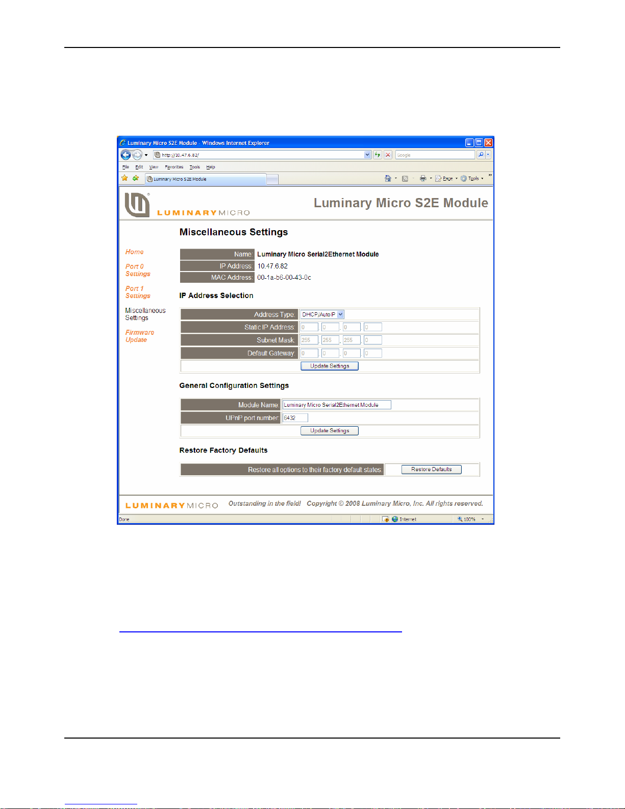
The Miscellaneous Settings page of the website is divided into three sections: “IP Address
Selection”, “General Configuration Settings”, and “Restore Factory Defaults”.
The “IP Address Selection” portion of the page allows configuration of the S2E module to
automatically obtain an IP address or use a static IP address at start up. If the “DHCP/AutoIP”
option is chosen, the S2E module will first attempt to get an IP address from a DHCP server. If a
DHCP server cannot be located, the S2E module will obtain a link local IP address using the
AutoIP protocol. If the “Static IP” option is chosen, then the “Static IP Address”, “Subnet Mask”,
and “Default Gateway” fields need to be filled in. Clicking the “Update Settings” button will cause
the settings to be saved.
The “General Configuration Settings” portion of the pa ge allows modification of the “Module Name”
and “UPnP port number”. Clicking the “Update Settings” button will cause the settings to be saved.
November 4, 2008 17
Page 18
Serial-to-Ethernet Configuration and Firmware Update
The “Restore Factory Defaults” portion of the page allows restoring all of the options to their
default states. Figure 2-4 shows the Miscellaneous Settings page of the website.
Figure 2-4. Miscellaneous Settings Page
Firmware Update Page
The Firmware Update page provides the capability for the application to call the boot loader to
initiate a firmware update over Ethernet. Once the bo ot loader is executing, LM Fla sh Programmer
can be used to update the firmware. LM Flash Programmer is provided o n the CD that comes with
the S2E RDK and can also be accessed from the Luminary Micro website at
http://www.luminarymicro.com/products/software_updates.html
The steps to complete the firmware update:
1. Using LM Flash Programmer
a. Start the LM Flash Programmer GUI.
b. On the Configuration tab, select “Manual Configuration” from the “Quick Set” pull-down
menu.
18 November 4, 2008
.
Page 19

Stellaris® S2E RDK User’s Manual
c. Select the “Ethernet Interface” option from the “Interface” pull-down menu.
d. Complete the “Client IP Address” field with the IP address shown on the Firmware Update
page.
e. Complete the “Client MAC Address” field with the MAC address shown on the Firmware
Update page.
f. Select the Ethernet Adapter of the PC to use.
g. Select to the Program tab. Click the “Browse” button and select the binary file for the
updated firmware.
2. Using LM Flash Programmer
Click the “Program” button.
3. If after a few seconds the LM Flash Programmer status bar does not ind icate that the update is
in progress, using the Firmware Update Page, click the "Update" button.
November 4, 2008 19
Page 20

Serial-to-Ethernet Configuration and Firmware Update
20 November 4, 2008
Page 21
Network
Ethernet
Power
Serial-to-Ethernet Module
Serial
Serial-only Device # 1
Power
Serial -to-Ethernet Module
Serial
Serial-on ly Device # 2
T
e
l
n
e
t
D
a
t
a
CHAPTER 3
Using the S2E Module as a Serial Extender over
Ethernet
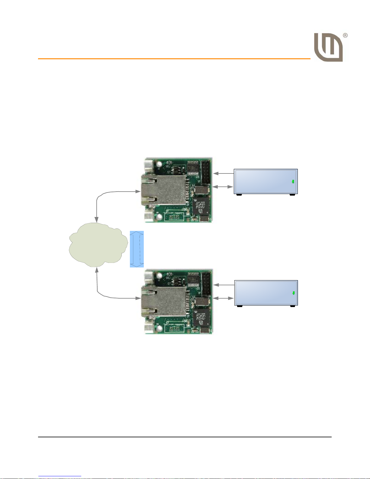
The application that comes preprogrammed into the S2E module is capable of implementing a
serial extender over Ethernet using two S2E modules. This scenario is used to connect two serial
devices over a network. This can be useful to overcome cable length limitations. Figure 3-1shows
a typical situation for doing this.
Figure 3-1. Implementing a Serial Extender over Ethernet
Below are the steps for creating a serial extender example. For this example, the two serial
November 4, 2008 21
devices are two PCs. In addition, the following assumptions are made: the two S2E modules are
connected to a network with a DHCP server so an IP address can be automatically acquired, the
two S2E modules are connected to the same subnet as a PC that can be used to configure them,
the S2E modules have the factory default settings, and that connector board port 0 is the serial
port being used for both S2E modules.
Page 22

Using the S2E Module as a Serial Extender over Ethernet
NOTE: In a longer term situation, the two S2E modules would be configured to have static IP
addresses since IP addresses can change over time when using DHCP.
1. Connect the serial port of one of the S2E modules to the serial port of a PC.
2. Connect the serial port of the other S2E module to the serial port of another PC.
3. Connect both S2E modules to a network with a DHCP server.
4. Power both S2E modules.
5. After the modules power up, both will automatically be configured as telnet servers by default.
One will need to be configured to be a telnet client. Use a PC to double-click on one of the
UPnP icons that corresponds to one of the S2E modules. This will load the configuration
website for that S2E module. For details on accessing and using th e configuration website,
see the S2E Configuration and Firmware Update
6. Once the configuration page is loaded, click the link for “Port 0 Settings”.
7. Configure the “T elnet Mode” to be “Client”, the “Local Telnet Port Number” and “Remote Telnet
Port Number” to be 23, and the “Telnet Server IP” to be the IP address of the other S2E
module.
8. Open HyperTerminal on each of the PCs connected to the S2E modules. For each instance of
HyperTerminal, select the COM port used by that PC to connect to the S2E module (most
likely COM1) and configure it for 115200 bits per second, 8 data bits, no parity, 1 stop bit, and
no flow control.
section.
9. Once HyperTerminal is started and configured on each of the PCs, messages can be sent
from one PC to the other by simply typing in the HyperTerminal window. Note that the default
HyperTerminal settings will not display the typed characters in the transmitting window.
22 November 4, 2008
Page 23
Network
EthernetEthernet
Virtual COM Port
Power
Serial-to-Ethernet Module
Serial
Serial-only Device
Telnet Data
Computer with COM 0COM and
CO M2TCP s o ftwa re ins t a ll e d
CHAPTER 4
Using Serial-to-Ethernet as a Virtual COM Port
The S2E module can be configured to appear as a virtual COM port (VCP) on a comp uter runnin g
Windows. VCP software is provided on the RDK Documentation and Software CD.
Overview
The Virtual COM port (VCP) feature allows legacy software that only supports serial
communication to communicate with a serial-only device over Ethernet.
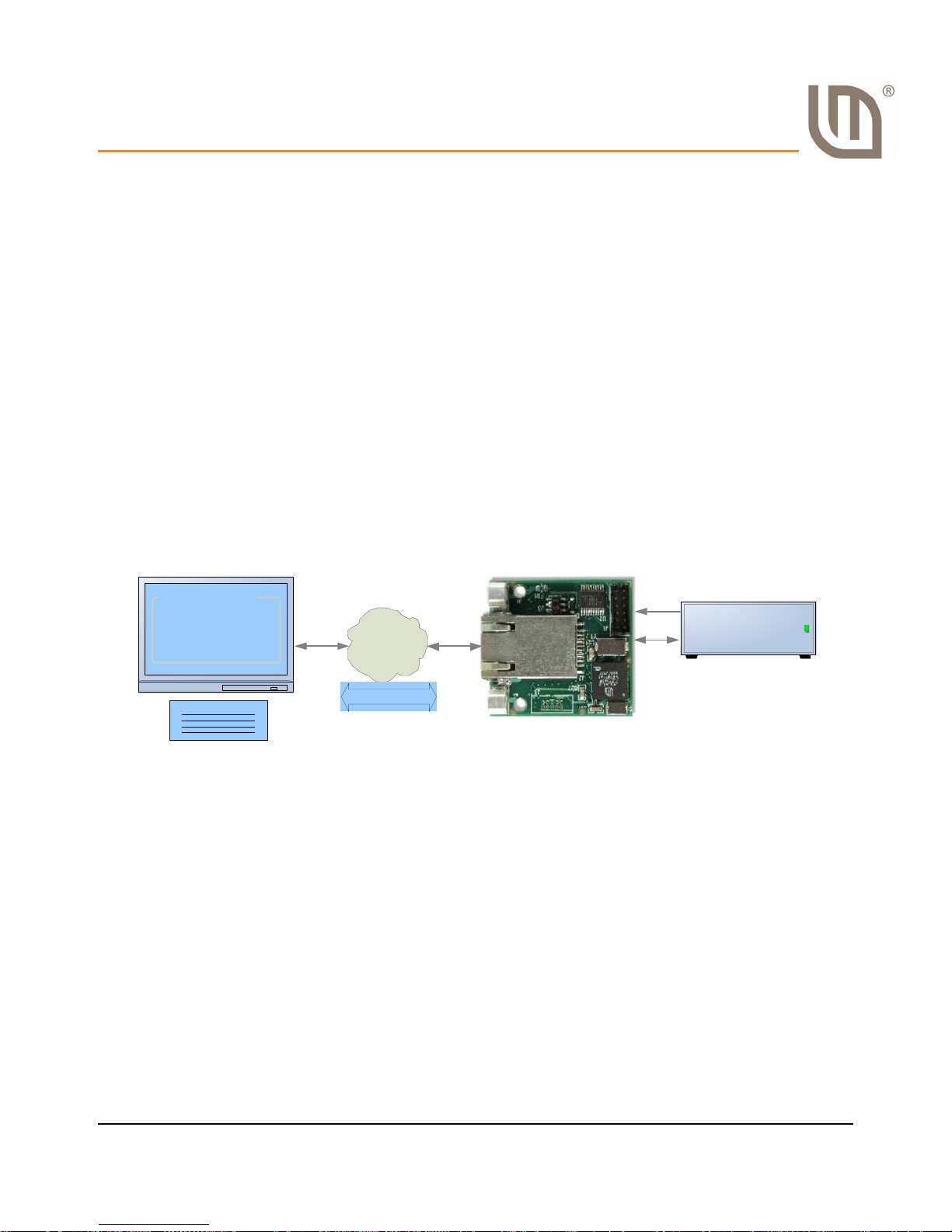
Figure 4-1 shows a typical S2E module application. This section describes how to install the VCP
software necessary to map the S2E module to a Windows COM port. VCP operation requires two
separate applications. The first, com0com creates a virtual COM port pair. Then com2tcp links one
half of the virtual COM port pair to the S2E module. The application software (for example,
HyperTerminal) connects to the other half of the virtual COM port pair.
To easily set-up and configure com0com and com2tcp connections to specific modules, use the
LM S2E Configuration application included on the sof tware CD.
Figure 4-1. Typical S2E Module
Before configuring VCP please complete all steps in the S2E Quickstart Guide and get familiar
with using the web configuration interface.
Install com0com
Com0com is an open source virtual serial port driver for Windows. Once installed it will configure
one or more pairs of virtual COM ports each time Windows starts.
1. Insert the RDK Documentation and Software CD into the CD-ROM drive of your computer. If
Autoplay is enabled on your PC, the index.htm file automatically opens in your default web
browser. If not, use Windows Explorer or other browser to open the index.htm file manually.
2. From the CD menu, click the Install com0com button; this will start the installation process. If
you prefer to manually install com0com, the setup.exe file is located in the /Software/com0com
November 4, 2008 23
directory.
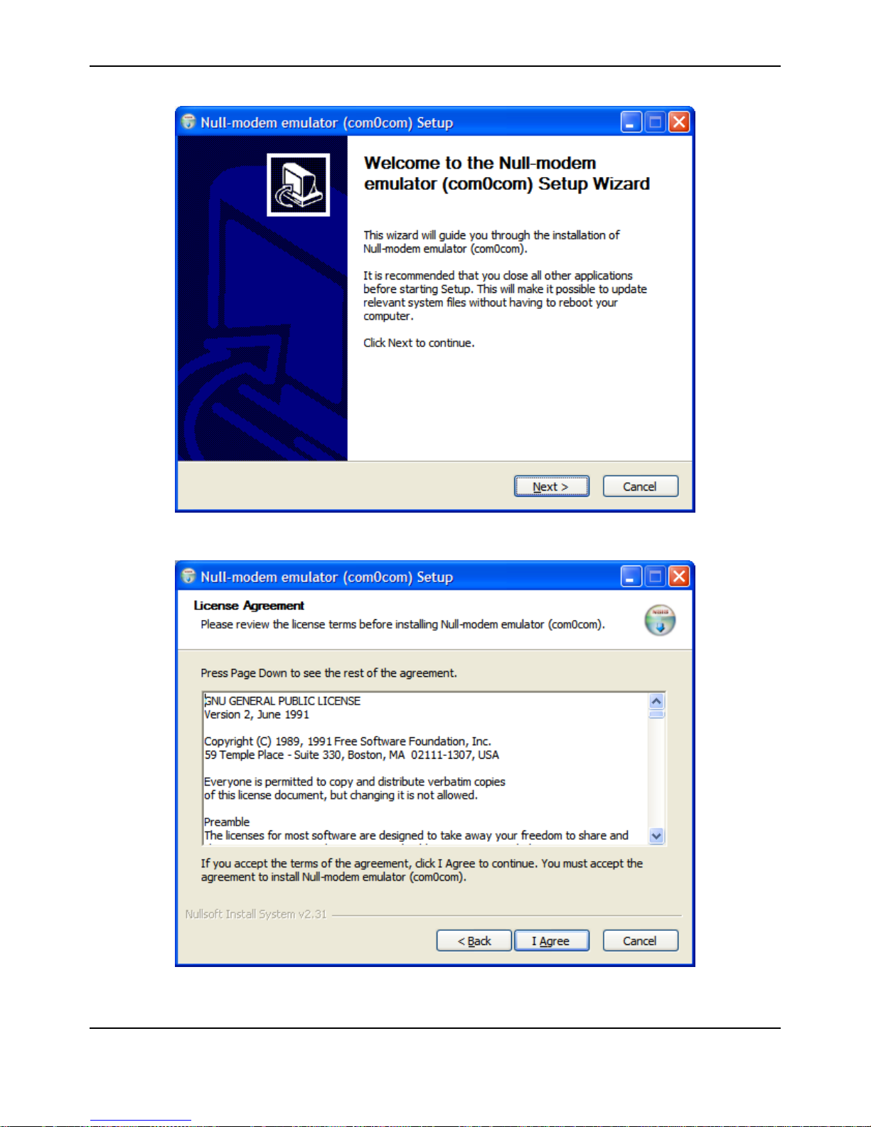
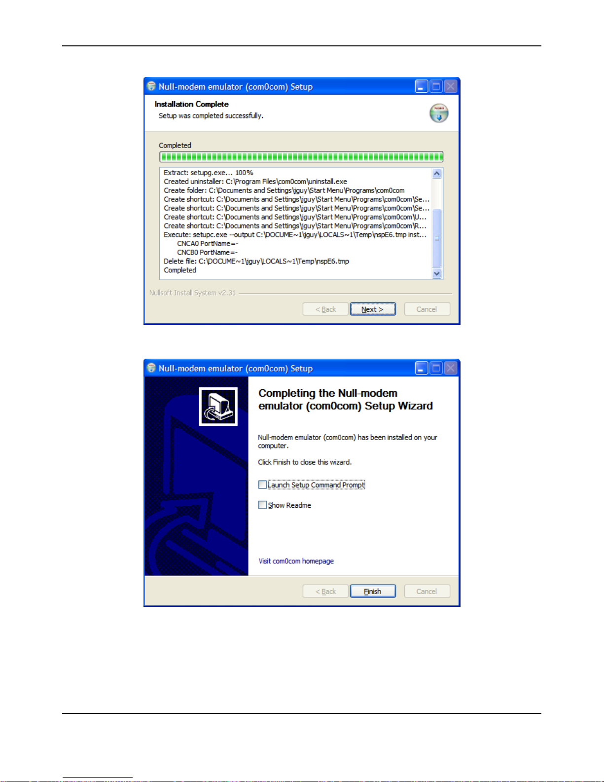
3. Com0com installation starts with the following dialog.
Page 24
Using Serial-to-Ethernet as a Virtual COM Port
a.
Click Next.
b.
Click I Agree.
24 November 4, 2008
Page 25
Stellaris® S2E RDK User’s Manual
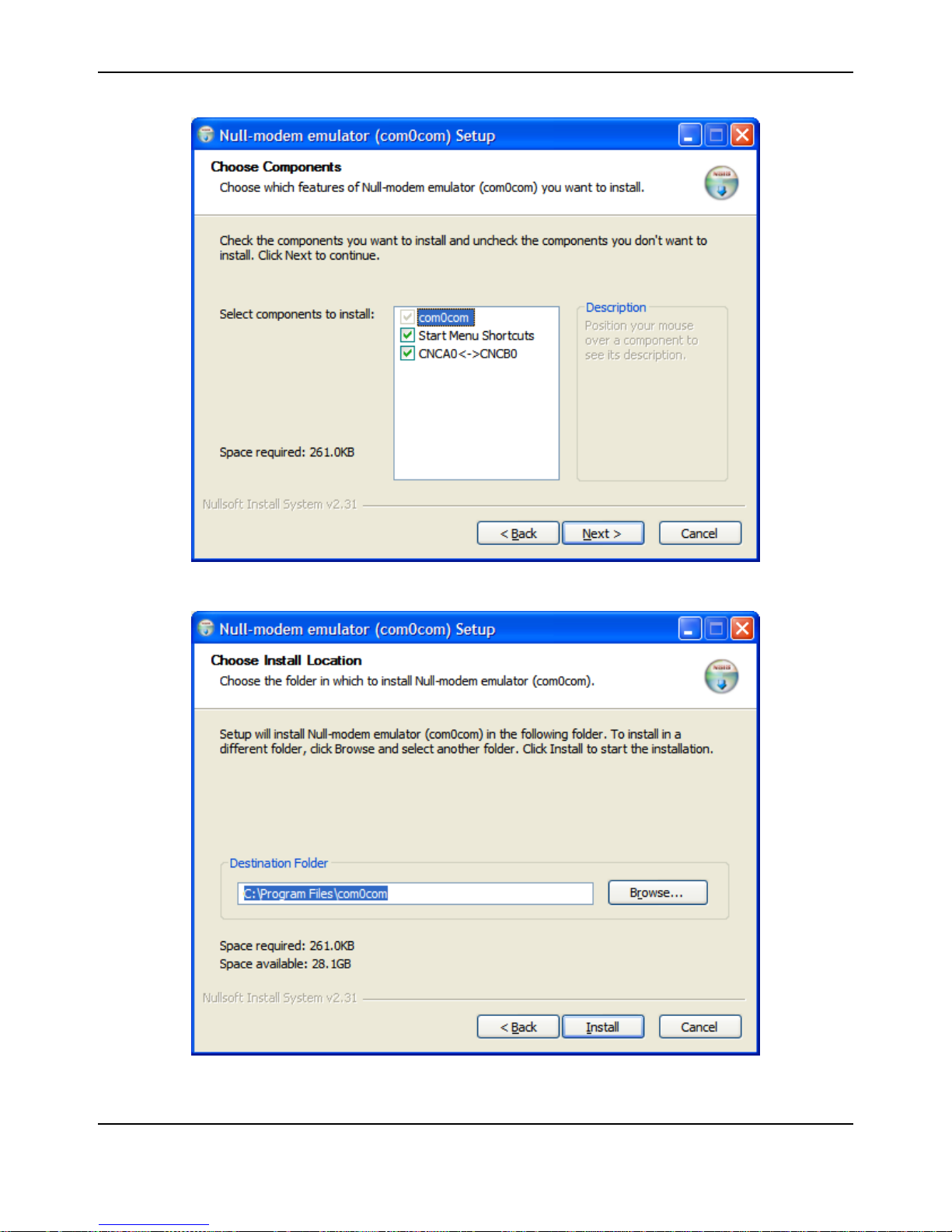
c.
Leave the Component setup at the default settings. Click Next.
d.
Choose the Install Location. Click Install.
November 4, 2008 25
Page 26
Using Serial-to-Ethernet as a Virtual COM Port
e.
Installation will complete. When installation is done click Next.
f.
Click Finish.
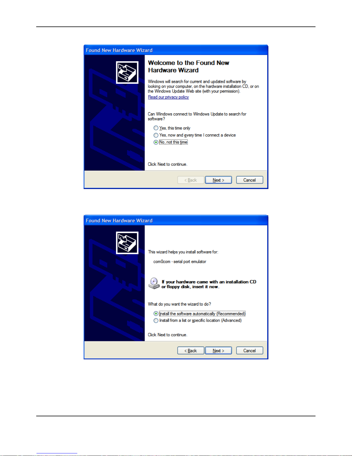
The Windows New Hardware Wizard will now run automatically for each of the two new Virtual
COM ports. Please complete the following steps twice.
26 November 4, 2008
Page 27
Stellaris® S2E RDK User’s Manual
g.
Windows will detect the new Com port. When the New Hardware Wizard run, select No, not this
time and click Next.
h.
Select Install the software automatically. Click Next.
November 4, 2008 27
Page 28
Using Serial-to-Ethernet as a Virtual COM Port
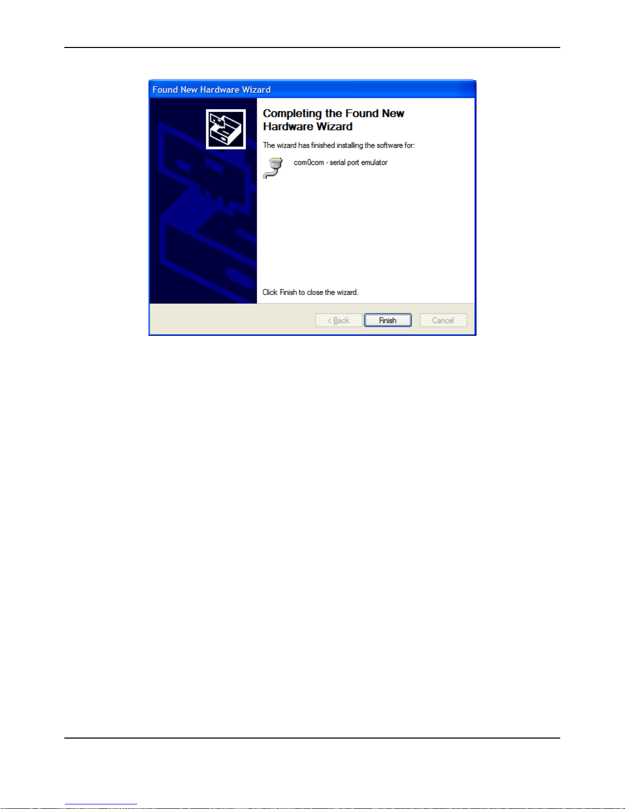
i.
When the New Hardware Wizard completes, click Finish.
Repeat for the second half of the Virtual Com port pair.
Com0com has now created virtual Com ports CNCA0 and CNCB0. These ports will be visible to
Windows serial applications such as HyperTerminal. The port names can be change by running
the LM S2E Configuration application. For LM S2E Configuration application installation
instructions, see “Install LM PC S2E Configuration” on page 28.
Install com2tcp
Com2tcp is an open-source project used in conjunction with com0com to redirect data traffic from
a virtual COM port on the PC to a telnet server or client on the Ethernet network. To install
com2tcp:
1. In the RDK documentation and software CD menu, select Install com2tcp.
2. In the Install com2tcp page that appears, right-click com2tcp application.
3. When prompted, select Save Ta rget As and navigate to your selected installation location. It
is recommended that you install com2tcp in the same directory as com0com; by default this is
C:\Program Files\com0com.
Install LM PC S2E Configuration
The Serial-to-Ethernet PC Configuration application of fers a convenien t meth od of se tting up VCP
connections to S2E modules. It allows the creation of com0com virtual COM ports and their
connection to particular S2E modules using com2tcp. To install the LM S2E Configuration
application:
1. In the RDK documentation and software CD menu, select Windows Configuration Utility -
Download.
2. When the Welcome window appears, click Next.
28 November 4, 2008
Page 29
Stellaris® S2E RDK User’s Manual
3. In the license agreement window, select I Agree and click Next.
4. In the Installation Options window, selecting Start all connections automatically
(recommended) allows the application to automatically start all appropriately configured VCP
connections when Windows boots and adds the option “LM S2E Launcher” under All
Programs in the Windows Start menu.
5. Click Next.
6. Choose the desired installation location or use the default installation location indicated. Click
Next.
7. Click Next to confirm the installation process and start copying application files.
8. When the Installation Complete window appears, click Close.
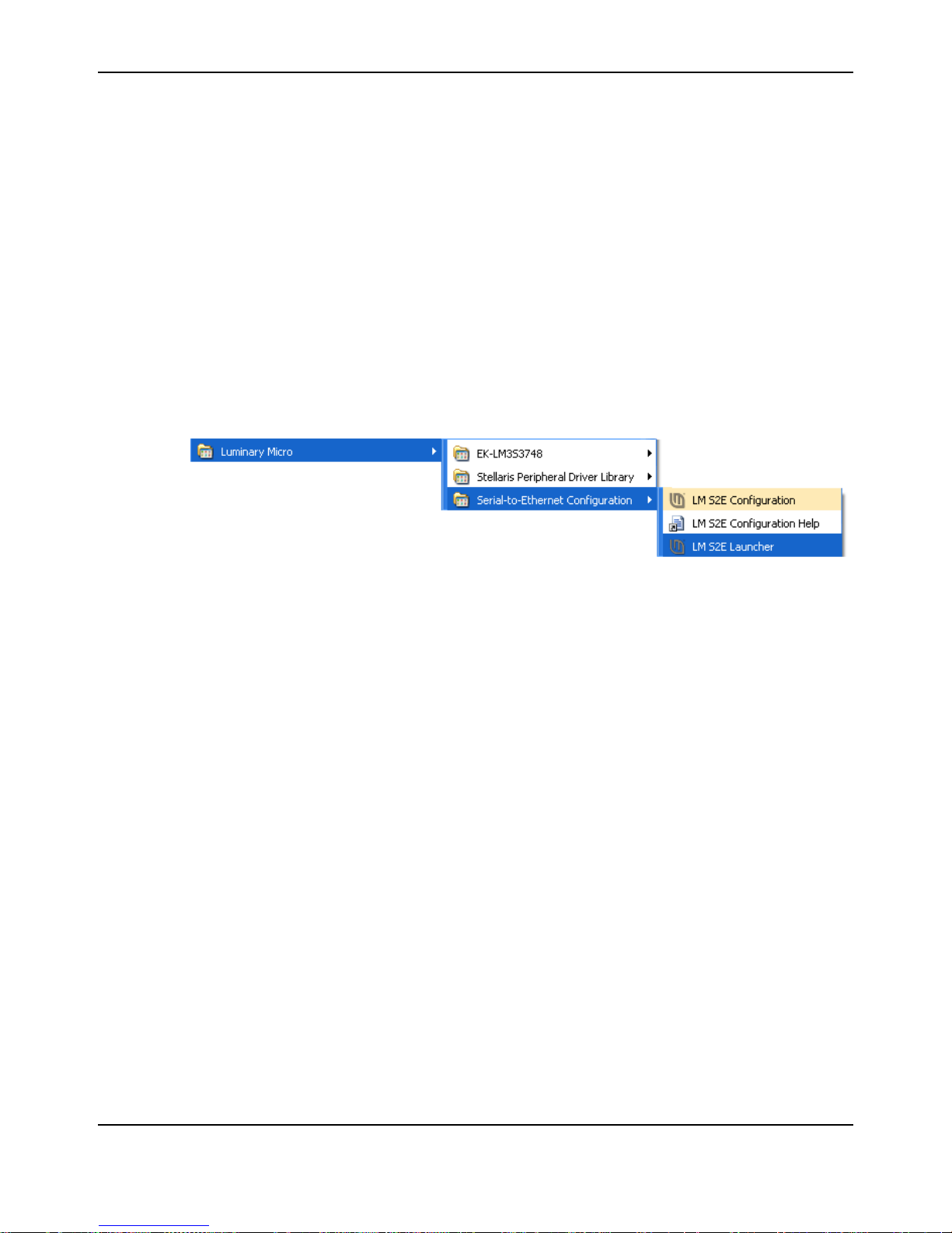
After installation completes, review the options available in your Windows Start menu. You should
see the menu group highlighted in Figure 4-2.
Figure 4-2. Luminary Micro menu group
After selecting Start > All Programs > Luminary Micro > Serial-to-Ethernet Configuration:
To start the PC Configuration application, select LM S2E PC Configuration. For instructions
on how to do this, see “Configure VCP Using the LM S2E PC Configuration Application” on
page 29.
To view the ap plication’ s help file, select LM S2E PC Conf ig uration He lp or press the F1 key
while the application is running.
To start VCP connections to S2E modules, if not automatically started upon Windows boot
(see step 4 of “Install LM PC S2E Configuration”), select the LM S2E Launcher companion
application. To search for S2E modules on the network and access their configuration pages,
select LM S2E Browser.
Configure VCP Using the LM S2E PC Configuration
Application
The LM S2E Configuration application offers easy creation and modification of VCP connections
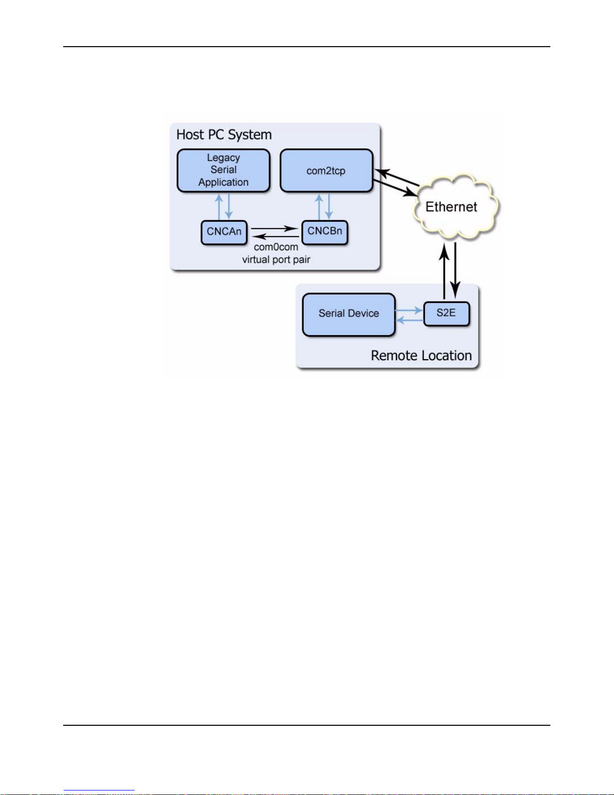
using a single application. Such connections contain several components:
The legacy serial application connects to a virtual COM port on the PC. This port is one of a
pair created using com0com. From within the LM S2E Configuration application you can
create new port pairs and edit the names of existing port s to cater to serial applicatio ns that do
not understand the default CNCA/CNCB naming convention used by com0com.
The second port in the pair is opened by com2tcp, which creates a telnet connection to the
remote S2E module over Ethernet. The Configuration application lists all S2E modules it finds
and offers a convenient method for accessing their web-based configuration pages.
November 4, 2008 29
Page 30
Using Serial-to-Ethernet as a Virtual COM Port
The S2E module connects to the remote serial device, as shown in Figure 4-3.
Figure 4-3. S2E module connection over Ethernet
Connection creation
The LM S2E Configuration application gathers the information necessary for creating these
connections using com0com and UPnP and then saves entries in the system registry, which are
later read by the LM S2E Launcher companion application when it starts the connections.
The connections created here assume that the S2E module is running as a telnet server, which is
the default for this module.
To create a new connection between a virtual COM port on the PC and remote device:
1. Select Start > All Programs > Luminary Micro > Serial-to-Ethernet Configuration > LM
S2E PC Configuration.
The first time the application starts it ensures that com0com and com2tcp are present. If you
did not install these in the default locations, the application prompts you for the location of
each. You only have to provide this location information once and will not be reprompted
unless you remove one or both packages or move one or both packages to a new location. If
one or other of the packages is not installed, the application will continue to run but will offer
the, “LM S2E Browser” functionality and not show any com0com/com2tcp options.
2. Once the application locates both the com0com and com2tcp packages, the main application
window appears, as shown in Figure 4-4.
30 November 4, 2008
Page 31
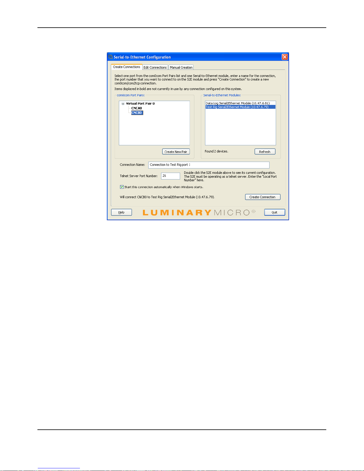
Figure 4-4. Main LM S2E Configuration application window
Stellaris® S2E RDK User’s Manual
3. The application performs a UPnP query to discover all S2E modules on the network. Once this
query completes, the Serial-to-Ethernet Modu les pane of the main applicatio n window updates
to show a complete list of the modules found. Once this list appears, select the module to
which you want to set up a connection. Double-click a module to launch its configuration
website.
4. In the com0com Port Pairs pane, click the + to the left of Virtual Port Pair 0 to expand the
listing. Select one of the two virtual COM ports listed. This is the port that com2tcp will use in
the connection you are configuring.
5. Enter a Connection Name for this connection.
6. Enter the Telnet Server Port Number (TCP/IP port number) for the S2E module and serial
port.
To find the Telnet Server Port Number, double-click the configuration module’s listing to go to
its website. Then, go to the Status & Configuration page and locate the Local Telnet Port
Number row , and select the number for the serial con nection, Port 0 or Port 1, that you wish to
use with this connection.
7. Select Start this connection automatically when W indows st art s. This ensures that the LM
S2E Launch companion application automatically starts the connection.
If you do not select this option, the LM S2E Launcher app lication does not st art the connection
even if you run it manually, unless you provide the -a command line option that instructs the
launcher to start all connections.
8. Click Create Connection to save the information on the newly configured connection for
future use by the LM S2E Launcher.
November 4, 2008 31
Page 32

Using Serial-to-Ethernet as a Virtual COM Port
Notice that Virtual Port Pair 0 is no longer bolded, indicating that the port pair is already in
use and you cannot configure another co nn ection using the same pair.
To create another VCP pair for use by your second (or subsequent) connection, click Create
New Pair and repeat the process, beginning with step 4, selecting newly created virtual port
pair listing.
9. Select Start > All Programs > Luminary Micro > Serial-to-Ethernet Configuration > LM
S2E Launcher . The launcher application reads the con nection information you just configu red
and starts com2tcp to initiate a connection with the desired S2E module.
10. You can now start your legacy serial application and open virtual COM port CNCA0 and
communicate with the remote serial device attached to the S2E module.
Edit port names
Some serial applications are unable to connect to a serial port named using a form other than
COMm, where m is the port number. Since com0com ports are named CNCAn and CNCBn by
default, this can cause problems. If you encounter this problem, the LM S2E Configuration
application allows you to change the names of virtual COM port s, as long as neither port in the pair
is currently part of a configured connection.
To edit the port name, expand the virtual port pair listing that con tains the por t you want to ch ange.
Double-click the port name, edit the connection name, and press ENTER.
Manual VCP Configuration
If you do not want to install the LM S2E Configur ation ap plication, you can manually configu re and
start com0com and com2tcp connections.
To manually create a virtual port pair , select All Programs > com0com > setup. Once you create
a virtual port pair, com2tcp establishes a link between one of the two ports in the pa ir a nd th e S2E
module. You can select either port for use with com2tcp.
You must also know the following:
The module’s IP address
For information on determining the IP address using My Network Places, see the S2E RDK
Quickstart document.
The module’s telnet port number
The default telnet port numbers are 23 and 26. For information on determining the specific
telnet port numbers, see the S2E RDK Quickstart document.
The process for manual VCP configuration shown here assumes the creation of a com0com port
pair with the default name, as occurs with initial installation of the com0com package, and that
com2tcp will use CNCB0 and the legacy serial application will use CNCA0.
1. Open a command prom pt window; to do this, select Start > All Programs > Accessories >
Command Prompt.
2. Change to the installation location for com2tcp.
3. At the command prompt, enter
com2tcp --telnet \\.\<CNCB0> <IP address> <telnet port>
where
– <CNCB0> is the name of the VCP used by com2tcp, for which CNCB0 is the default name
32 November 4, 2008
Page 33
Stellaris® S2E RDK User’s Manual
– <IP address> is the actual S2E IP address; for example, 169.254.5.67
– <telnet port> is the actual telnet port number; for example, 23
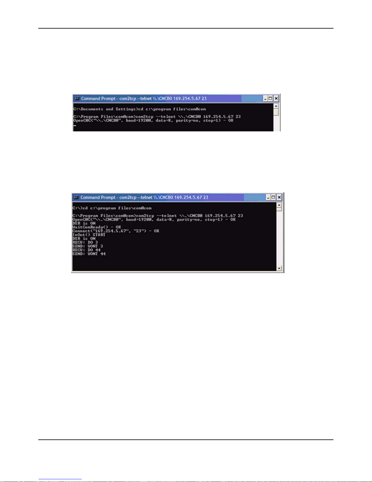
For an example of this command string and the module’s response, see Figure 4-5.
Figure 4-5. Manual VCP configuration
Com0com now has an established link between the S2E module and virtual COM port CNCB0,
allowing Windows applications to connect to the S2E module through the virtual COM port CNCA0
(the port used by the legacy serial application). When communication occurs, com2tcp provides
status information in the command prompt window, as shown in Figure 4-6.
Figure 4-6. Com2tcp communication shown in the command prompt window
If you need to end com2tcp, click the command prompt window to be sure it is the active window
and press CTRL+C.
Verify VCP Operation
Connect the S2E hardware (as described in the Quickstart Guide). Open two HyperTerminal
windows, one Virtual COM port and one standard COM port, as follows:
1. Open one HyperTerminal window. On Windows XP, HyperTerminal can be found by clicking
Start, Programs, Accessories, and then Communications.
2. Enter a name for the terminal window and click OK.
3. In the Connect Using pull-down menu, select the COM port associated with the port that the
DB9 cable is connected to on your PC and click OK.
4. Select 115200 for Bits per second, 8 for Data bits, None for Parity, 1 for Stop Bits, and
None for Flow Control.
5. Open another HyperTerminal window.
6. Enter a name for the terminal window and click OK.
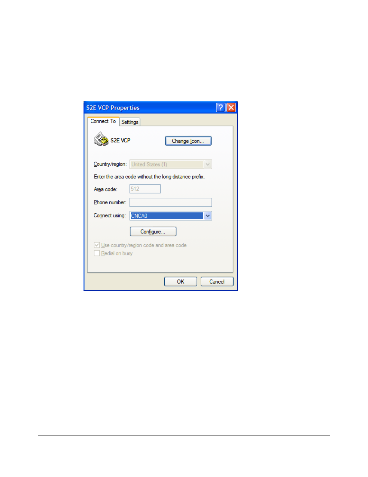
7. In the Connect Using pull-down menu, select CNCA0. Then click OK.
November 4, 2008 33
Page 34
Using Serial-to-Ethernet as a Virtual COM Port
8. Now you can type in one of the HyperT erminal windows and see the text displayed in the other
HyperTerminal window. This demonstrates the S2E module converting seri al data to Ethernet
and vice versa.
Figure 4-7 show the HyperTerminal File Properties Dialog configuration. In this example, the
connection was named S2E VCP.
Figure 4-7. HyperTerminal File Properties Dialog
Com0com and com2tcp are open-source (GPL) projects. For additional information and source
code for the com0com and com2tcp, refer to the S2E documenta tion and source code CD or
search the Internet for the respective project name.
34 November 4, 2008
Page 35
XV_U0TX
XV_U0RX
XV_U0RTS
XV_U0CTS
3.3V
5V
U1TX
U1RX
U1RTS
U1CTS
RSTn
GND
LM3S6432
U1TX
U1RX
U1RTS
U1CTS
21
12
11
RSTn
GND
3.3V
regulator
J1
PA0
PA1
PB0
PB1
PD2/PA4
PD3/PA5
PA3
PA2
RST
Magnetics
CHAPTER 5
Hardware Description
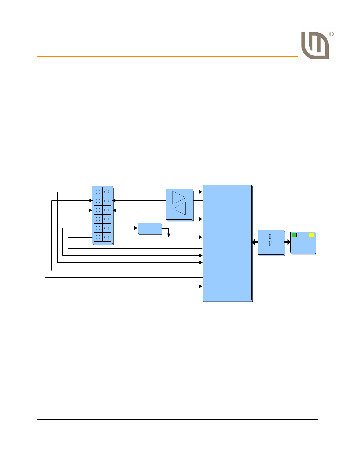
The Serial-to-Ethernet (S2E) board is a simple add-on product that provides serial UART to
Ethernet communications. Existing systems that lack Ethernet connectivity but have a UART port
can be easily upgraded by the addition of the S2E module. A simple web server is used for module
configuration.
The Serial-to-Ethernet Reference Design Kit (RDK) adds a second board (S2E-CKIT) with
connectors and cables for easy connection to a PC. All design files are provided on the RDK-S2E
CD.
Block Diagram
Figure 5-1 shows the S2E block diagram.
Figure 5-1. Serial-to-Ethernet Block Diagram
November 4, 2008 35
Page 36

Hardware Description
36 November 4, 2008
Page 37

APPENDIX A
Schematics
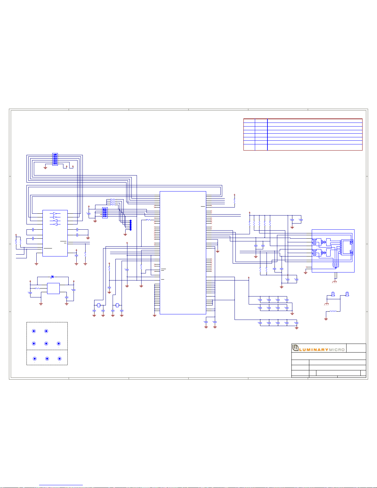
This sections contains the schematic diagram for the S2E Module.
Serial-to-Ethernet module on page 38
November 4, 2008 37
Luminary Micro Confidential—Advance Product Information
Page 38
1
1
2
2
3
3
4
4
5
5
6
6
D D
C C
B B
A A
Document Number: Rev
SheetDate: of
4/25/2008
11
RC
This document contains information proprietary to Luminary Micro, Inc. and shall not be used for
engineering design, procurement of manufacture in whole or in part without the express written
permission of Luminary Micro, Inc. Copyright © 2007 Luminary Micro, Inc. All rights reserved.
108 Wild Basin Rd.
Two Wild Basin Suite 350
Austin, TX 78746
Luminary Micro, Inc.
Designer:
Drawn by:
Approved:
Drawing Title:
Page Title:
Size
Arnaldo Cruz
Arnaldo Cruz
*
0001
SERIAL2ENET Module
FURY BGA108, UART Transceiver, RJ45 with Magnetics
C
C1
0.1uF
C14
0.01uF
C2
0.01uF
C13
0.1uF
C7
10pFC810pF
C11
10pF
C12
10pF
R5
49.9
R8
49.9
ETH_TXON
ETH_RXIP
ETH_RXIN
C36
18pF
3.3V
MDIO_PU
C35
18pF
C34
18pF
C33
18pF
Y2
25 MHz
ETH_RXIN
ETH_RXIP
C22
0.1uF
C23
0.1uF
C24
0.1uF
C28
0.1uF
C29
0.01uF
C30
0.01uF
C38
0.1uF
C39
0.1uF
C40
0.1uF
C41
0.01uF
3.3V
RST_n
XTALN
XTALP
OSC0
OSC1
LDO
C10
0.1uF
C42
0.1uF
C43
0.1uF
3.3V
R2
10K
R7
10K
R3
330R4330R649.9
R9
49.9
1 2
Y1
8.000 MHz
R1 0
U1RX_SPIRX
U1TX_SPITX
U1RX_SPIRX
U1TX_SPITX
U1CTS_SPICLK
U1RTS_SPISEL
U0RX
U0TX
FB1
40 ohm@100MHz_1.5A
ETH_LED1
ETH_LED0
XVR_OFF_n
XVR_ON
XVR_EN_n
XVR_INV_n
C20
0.47uF
5V 3.3V
XVR_ON
XVR_OFF_n
C3 0.47uF
C6 0.47uF
3.3V
C9
0.47uF
C4 0.47uF
C5 0.47uF
XVR_INV_n
XVR_EN_n
D1
MBR0520
1 2
3 4
5 6
7 8
9 10
JTAG/SWD
J3
HDR 2X5-MH
3.3V
TMS
TCK
TDO
TDI
SYSTEM
2
4
6
8
10
1
3
5
7
9
12 11
J1
HDR 2X6-SHRD
3.3V 5V
U1RX_SPIRX
U1TX_SPITX
U1RTS_SPISEL
U1CTS_SPICLK
XV_U0RX
XV_U0TX
XV_U0CTS
XV_U0RTS
U0RTS
U0CTS
RST_n
6
5
8
4
2
3
1
7
1CT:1
TX+
TXRX+
RX-
1CT:1
Y+
Y-
G+
G-
3
8
7
4
5
6
11
12
2
1
GL
GR
9
10
NC
GND
Ethernet 10/100
J2
PulseJack_RJ45_SMT
ETH_TXOP
3.3V
S1
SMT_RA_M3S2SMT_RA_M3
3.3V
R11
10K
C21
1uF
C27
1uF
C37
1uF
C18
0.47uF
Revision History
Revision
X0 1/16/2008 First release.
Date Description
X1 1/18/2008 Second release.
VIN4VOUT
5
VR
1
GND2CD
3
U3
PQ1N333MASPQ
C17
4.7uF
C19
4.7uF
RST_n
C15
0.1uF
R10 10K
R12 10K
R13 10K
R14 10K
R15 10K
X2 1/21/2008 Added JTAG pullups.
R16
10K
VCC
19
C2+
5
C2-
6
C1+
2
C1-
4
INVALID
11
V+
3
V-
7
T1IN
13
T1OUT
17
GND
18
R1OUT
15
R1IN
16
EN
1
T2OUT
8
T2IN
12
R2OUT
10
R2IN
9
FORCEON
14
FORCEOFF
20
U2
ICL3223
X3 1/25/2008 Added pulldown to U2 pin 1 to enable operation with ICL3223.
RA 1/26/2008 Released for manufacturing.
RB 2/12/2008 Fixed S1,S2 pads, rotated J3, fixed net names.
R17
10K
R18
10K
3.3V
RC 4/2/2008 Added pulldown resistor to U1-K3, added pullups to U2 to enable transceiver after reset.
R19
12.4K
PA0/U0RX
L3
PA1/U0TX
M3
PA2/SSI0CLK
M4
PA3/SSI0FSS
L4
PA4/SSI0RX
L5
PA5/SSI0TX
M5
PC0/TCK/SWCLK
A9
PC1/TMS/SWDIO
B9
PC2/TDI
B8
PC3/TDO/SWO
A10
PC4
L1
PC5/C1+
M1
PC6/CCP3
M2
PC7
L2
PD0/PWM0
G1
PD1/PWM1
G2
PD2/U1RX
H2
PD3/U1TX
H1
PD4
E1
PD5
E2
NC
F2
NC
F1
GND
C4
GND
C5
GND
H3
GND
J3
RST
H11
LDO
E3
OSC0
L11
OSC1
M11
PB0/CCP0
E12
PB1/CCP2
D12
PB2/I2C0SCL
C11
PB3/I2C0SDA
C12
PB4/C0-
A6
PB5/C1-
B7
PB6/C0+
A7
PB7/TRST
A8
PE0
A11
PE1
B12
PE2
B11
PE3
A12
PE4
D1
NC
D2
PA6/CCP1
L6
PA7
M6
NC
C2
NC
C1
PF0
M9
PF1
H12
PF2/LED1
J11
PF3/LED0
J12
MDIO
L9
TXON
L8
TXOP
M8
GNDPHY
K4
PG0
K1
PG1
K2
XTALNPHY
J1
XTALPPHY
J2
ERBIAS
K3
RXIP
M7
RXIN
L7
VCC
C10
GNDPHY
C9
GNDPHY
C8
VCCPHY
D11
VCCPHY
D10
VDDA
C6
VDDA
C7
AGND
A5
AGND
B5
VDD33
K7
VDD33
G12
VDD33
K8
VDD33
K9
VDD33
H10
VDD33
G10
VDD33
E10
VDD33
G11
GND
K5
GND
K6
GND
L10
GND
K10
GND
J10
GND
F10
GND
F11
GND
B6
GND
F12
VDD25
C3
VDD25
D3
VDD25
F3
VDD25
G3
WAKE
M10
HIB
M12
XOSC0
K11
XOSC1
K12
VBAT
L12
CMOD0
E11
CMOD1
B10
ADC0
B1
ADC1
A1
ADC2
B3
ADC3
B2
ADC4
A2
ADC5
A3
ADC6
B4
ADC7
A4
U1
LM3S6432
Renamed GNDPHY (U1-K3) to ERBIAS, fixed termination for ethernet RX signals. Added JTAG test pads.
80 Mil Mask
FID3
40 Mil Pad
80 Mil Mask
FID4
40 Mil Pad
80 Mil Mask
FID5
40 Mil Pad
80 Mil Mask
FID1
40 Mil Pad
80 Mil Mask
FID2
40 Mil Pad
Fiducials
Top
80 Mil Mask
FID6
40 Mil Pad
80 Mil Mask
FID7
40 Mil Pad
80 Mil Mask
FID8
40 Mil Pad
Bottom
TP1
TP2
TP3
TP4
TP5
TP6
Note:
ERBIAS resistor R19 required
for compatibility with future
revisions of the LM3S6432.
Schematic page 1
Page 39

APPENDIX B
Bill of Materials (BOM)
Table B-1 provides the BOM for the Serial-to-Ethernet RDK and Table B-2 provides the BOM for
the Serial-to-Ethernet connector board.
Table B-1. Serial-to-Ethernet Bill-of-Materials
Designator Comment Description Footprint MFG Ordering Qty
C1, C10,
C13, C15,
C22, C23,
C24, C28,
C38, C39,
C40, C42,
C43
C2, C14,
C29, C30,
C41
C3, C4, C5,
C6, C9,
C20
C7, C8,
C11, C12
C17, C19 4.7uF CAP, 0805, X7R, 4.7uF,
C21, C27,
C37
C33, C34,
C35, C36
D1 MBR0520 DIODE SCHOTTKY
0.1uF 1005[0402] MURATA GCM155R71C104KA
0.01uF 1005[0402] MURATA GRM155R71E103KA
0.47uF CAP , 0603, 0.47uF , 10%,
16V, X7R
10pF CAP, 0603, 10 pF, 10%,
25V, COG
20%, 10V
1uF CAP, 0805, X7R, 1uF,
10%, 10V
18pF CAP, 0402, C0G, 18pF,
50V
0.5A 20V
55D
01D
1608[0603] Murata GRM188R71C474KA
1608[0603] AVX 06033A100KAT2A 4
C0805 Murata GRM21BR61A475M
C0805 Murata GRM21BR71A105KA
1005[0402] MURATA GRM1555C1H180JZ
SOD-123 Fairchild
Semiconductor
88D
A73L
01L
01D
MBR0520L 1
13
5
6
2
3
4
J1 HDR 2X6-
SHRD
J2 PulseJack_RJ
45_SMT
R2, R7,
R10, R16
R3, R4 330 RES, SO, 0603, 330
R5, R6, R8, R949.9 RES, SO, 0603, 49.9,
S1, S2 SMT_RA_M3 SMT right angle
10K RES, SO, 0603, 10K,
HDR, SHROUDED 2x6,
2mm CTR
PulseJack RJ45 with
XFMR 1CT:1, TX, RX
SMT
1%, 1/10W
Ohm, 1%, 1/10W
1%, 1/10W
fastener, M3 thread
November 4, 2008 39
HDR2X6 - 2mm Hirose Electric CoDF11-12DP-
2DSA(24)
RJ45-SMT-J30 Pulse
Engineering
J1-0603 Vishay/Dale CRCW060310K0FKEA4
J1-0603 Vishay/Dale CRCW0603330RFKEA2
J1-0603 Vishay/Dale CRCW060349R9FKEA4
SMT_RA_M3 Penn
Engineering &
Manufacturing
(PEM)
J3011G21DNL 1
SMTRAM3-7-5ET 2
1
Page 40

Table B-1. Serial-to-Ethernet Bill-of-Materials (Continued)
Designator Comment Description Footprint MFG Ordering Qty
U1 ARM Cortex
M3
Microcontrolle
r
U2 ICL3223 RS-232 Transceiver, 2
U3 PQ1N333MA
SPQ
Y1 8.000 MHz XTAL 8.000MHz Crystal_NX8045 NDK NX8045GB-
Y2 25 MHz XTAL 25MHz SMT,
ARM Cortex-M3
Microcontroller
TX, 2 RX, 250Kbit
IC, 350mA LDO
regulator
50ppm
BGA108C80P12X12_
1000X1000X150
SSOP-20 Intersil ICL3223ECAZ 1
SOT89-5 Sharp
Crystal_NX5032 NDK NX5032GA-
Luminary Micro LM3S6432-IBZ50 1
PQ1N333MASPQ 1
Microelectronics
8.000000MHZ
25.000000MHZ
Table B-2. Serial-to-Ethernet Connector Board Bill-of-Materials
Designator Comment Description Footprint MFG Ordering Qty
D1 GREEN_LED LED GREEN SGL 20mA THLED-T1-3mm KINGBRIGHT WP132XGD 1
J1 SKT 2X6-
2mm
J2 HDR 1X6 HDR, 1x6 0.025" PIN,
SKT 2x6, 2mm CTR SKT2X6 - 2mm Hirose Electric CoDF11-12DS-2DSA 1
HDR1X6 Molex 22-28-4063 1
0.1" CTR
1
1
J3 HDR 1X2 HDR, 2x1, 0.025" PIN,
0.1" CTR
J4 DB9_F DB9_F DB9[47X70]-FEMALE T yco Electronics/
J5 USB Mini AB
Socket
R1 330 RES, SO, 0603, 330
CONN USB Min-AB
Socket through hole
Ohm, 1%, 1/4W
HDR1X2 Molex 22-28-4023 1
AMP
USB-miniAB Molex 56579-0519 1
AXIAL-0.4 KOA/Speer MF1/4DCT52R3300F 1
5747844-4 1
40 November 4, 2008
Page 41

APPENDIX C
Contact Information
Company Information
Luminary Micro, Inc. designs, markets, and sells ARM Cortex-M3-based microcontr ollers (MCUs).
Austin, Texas-based Luminary Micro is the lead partner for the Cortex-M3 processor, delivering the
world's first silicon implementation of the Cortex-M3 processor. Luminary Micro's introduction of
the Stellaris® family of products provides 32-bit performance for the same price as current 8- and
16-bit microcontroller designs. With entry-level pricing at $1.00 for an ARM technology-based
MCU, Luminary Micro's Stellaris product line allows for standardization that eliminates future
architectural upgrades or software tool changes.
Luminary Micro, Inc.
108 Wild Basin, Suite 350
Austin, TX 78746
Main: +1-512-279-8800
Fax: +1-512-279-8879
http://www.luminarymicro.com
Support Information
For support on Luminary Micro products, contact:
[email protected]
+1-512-279-8800, ext. 3
November 4, 2008 41
Page 42

42 November 4, 2008
 Loading...