

Page 1
LSProbe 1.2 Quick Start Guide
LUMILOOP GmbH
March 12, 2018
The most recent version of this document and the
full length LSProbe 1.2 User’s Manual can be found at
❤tt♣✿✴✴✇✇✇✳❧✉♠✐❧♦♦♣✳❞❡
.
1 System Overview
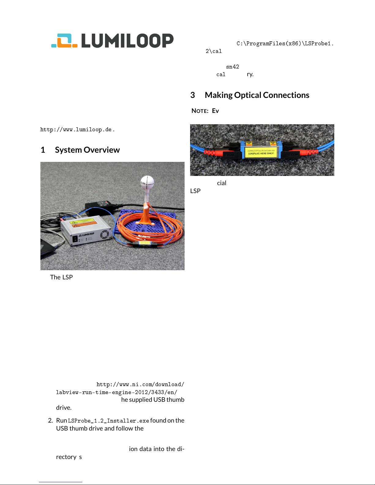
The LSProbe 1.2 system consists of the optically
powered E-Field Probe and the Computer Interface
shown above. The Computer Interface is connected
to the host computer via USB 2.0.
The LSProbe TCP Server handles all USB communication. The LSProbe GUI and other third party EMC
software access theLSProbe1.2 TCP using SCPI commands exchanged via a TCP/IP connection.
2 Software Installation
1. Install the National Instruments „32 bit LabVIEW 2012 Run Time Environment“ via download from
❤tt♣✿✴✴✇✇✇✳♥✐✳❝♦♠✴❞♦✇♥❧♦❛❞✴
❧❛❜✈✐❡✇✲r✉♥✲t✐♠❡✲❡♥❣✐♥❡✲✷✵✶✷✴✸✹✸✸✴❡♥✴
or start it directly from the supplied USB thumb
drive.
2. Run
▲❙Pr♦❜❡❴✶✳✷❴■♥st❛❧❧❡r✳❡①❡
found on the
USB thumb drive and follow the installation instructions.
3. Copy the supplied calibration data into the directory selected during TCP Server and GUI
installation. E.g. if the calibration data directory is
❈✿❭Pr♦❣r❛♠❋✐❧❡s✭①✽✻✮❭▲❙Pr♦❜❡✶✳
✷❭❝❛❧
and the serial number of the E-Field
Probe is 42, please copy the whole directory
named
s♥✹✷
from the installation medium into
the
❝❛❧
directory.
3 Making Optical Connections
NOTE: Every LSProbe 1.2 is delivered with plugged
optical connectors and ready to use.
Sacrificial optical cables are supplied with each
LSProbe E-Field Probe. Always use the E2000 connectors shown above for breaking and making the
optical connection. The E2000 connectors of the
sacrificial cable assembly include automatic shutters
preventing contamination and resulting optical fiber
burn-in. Nevertheless, all optical connectors must be
kept in a perfectly clean condition at all times.
In case of a fiber connector burn-in only a pair
of sacrificial cables need to be replaced, allowing for
rapid and cost-effective fault recovery without requiring external service.
For detailed instructions, consult the LSProbe 1.2
User’s Manual, Section 5.1.1 .
4 System Startup
1. Connect the included mains adapter to the
Computer Interface.
2. Connect the Computer Interface to the host
computer using the included USB cable.
3. Switch on the Computer Interface setting the
front panel switch to 1 and observe the green
power LED starting to flash. If the host computer has access to the on-line Microsoft Windows Update, the USB driver will be installed
automatically.
Page 2
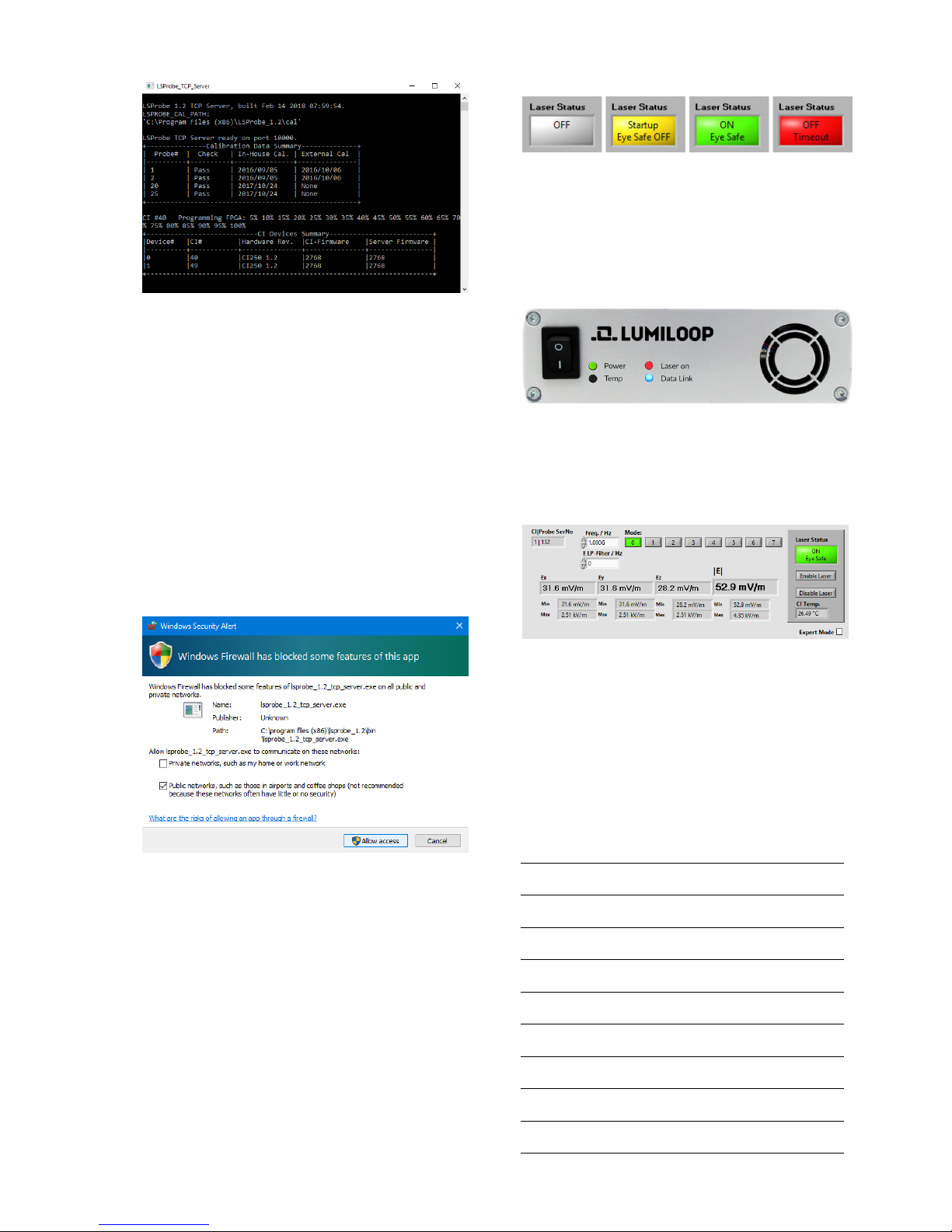
4. Start the LSProbe TCP Server via the Windows
Start Menu and check that the green power
LED is constantly on. The LSProbe TCP Server
will display a list of detected calibration data
sets and a list of all detected Computer Interfaces as shown above.
If this step fails, consult the LSProbe 1.2 User’s
Manual, Section 4.2 .
5. Since the LSProbe TCP Server needs to open
a TCP port, the system’s firewall may ask for
permission for network access. Access must
be granted as shown below in order to run the
LSProbe TCP Server, the default TCP port number is 10,000.
5 LSProbe GUI Operation
1. Start the LSProbe GUI via the Windows Start
Menu.
2. Click the “Enable Laser” button to activate the
supply laser and turn the E-Field Probe on. The
Computer Interface’s orange “Laser on” indicator LED will show the activity of the supply
laser.
WARNING: When the orange LED is flashing, Automatic Power Reduction (APR) is disabled. Interrupting optical connections is dangerous!
The GUI indicates proper operation by displaying a green “Laser Status” indicator as shown
above. Stable operation is indicated by the
Computer Interface’s continuously on “Power”,
“Laser on” and “Data Link” LEDs as shown below.
3. As shown below, the E-field strength values
for x, y, z components and the isotropic field
strength are displayed by the GUI, maximum
and minimum calibrated field strength for the
set mode and frequency are displayed below.
4. For accurate E-field strength measurements
the field’s frequency must be specified using the
“Freq./Hz” input field. Values are entered in
Hertz, SI unit prefixes may be used, e.g. “1G” for
1 GHz, as shown above.
5. For advanced features use the “Expert Mode”
radio button.
PERSONAL NOT ES:
 Loading...