


Lumikit Sistemas para Iluminação
Lumikit Sistemas para IluminaçãoLumikit Sistemas para Iluminação
Lumikit Sistemas para Iluminação
| www.lumikit.com.br
1111
READ THE MANUAL BEFORE USE THE PRODUCT!
READ THE MANUAL BEFORE USE THE PRODUCT!READ THE MANUAL BEFORE USE THE PRODUCT!
READ THE MANUAL BEFORE USE THE PRODUCT!
User manual
User manualUser manual
User manual
Lumikit PRO X4 interface
Lumikit PRO X4 interfaceLumikit PRO X4 interface
Lumikit PRO X4 interface
Lumikit PRO X4 RACK interface
Lumikit PRO X4 RACK interfaceLumikit PRO X4 RACK interface
Lumikit PRO X4 RACK interface
© 2015 Lumikit Sistemas para Iluminação
rev.1 –
01/25/
2015

Lumikit Sistemas para Iluminação
Lumikit Sistemas para IluminaçãoLumikit Sistemas para Iluminação
Lumikit Sistemas para Iluminação
| www.lumikit.com.br
2222
Important considerations, read before using the product
Important considerations, read before using the productImportant considerations, read before using the product
Important considerations, read before using the product::::
Before starting it is important to have some knowledge in computer network and network addressing, see the following topics in the
internet:
• http://pt.wikipedia.org/wiki/Endereço_IP
• http://pt.wikipedia.org/wiki/Comutador_(redes)
The
The The
The difference between the Lumikit PRO X4 and
difference between the Lumikit PRO X4 anddifference between the Lumikit PRO X4 and
difference between the Lumikit PRO X4 and Lumikit PRO X4 RACK interface is the cabinet
Lumikit PRO X4 RACK interface is the cabinet Lumikit PRO X4 RACK interface is the cabinet
Lumikit PRO X4 RACK interface is the cabinet
and the power supply, as the power supply is different from one model to another, the isolation
and the power supply, as the power supply is different from one model to another, the isolation and the power supply, as the power supply is different from one model to another, the isolation
and the power supply, as the power supply is different from one model to another, the isolation
is also different, see more information in chapter 1 and chapter 10.
is also different, see more information in chapter 1 and chapter 10.is also different, see more information in chapter 1 and chapter 10.
is also different, see more information in chapter 1 and chapter 10.
The network cable supplied with the interf
The network cable supplied with the interfThe network cable supplied with the interf
The network cable supplied with the interface is a straight one
ace is a straight oneace is a straight one
ace is a straight one,
, ,
, if the interface is connected
if the interface is connected if the interface is connected
if the interface is connected
directly
directly directly
directly in
inin
in older computer
older computerolder computer
older computerssss,
, ,
, it might be necessary to use a crossover
it might be necessary to use a crossover it might be necessary to use a crossover
it might be necessary to use a crossover network
network network
network cable
cablecable
cable....
The
The The
The GROUND
GROUNDGROUND
GROUND pin from the
pin from the pin from the
pin from the power supply
power supplypower supply
power supply con
concon
connnnnector is connect
ector is connectector is connect
ector is connected to
ed toed to
ed to the
thethe
the interface housing
interface housinginterface housing
interface housing (on
(on (on
(on
the RACK version)
the RACK version)the RACK version)
the RACK version)....
We
We We
We recommend the use of a
recommend the use of a recommend the use of a
recommend the use of a terminator resistor in the last DMX device of the line, the
terminator resistor in the last DMX device of the line, the terminator resistor in the last DMX device of the line, the
terminator resistor in the last DMX device of the line, the
terminator resistor consists in a 120 ohms resistor and 1/2W or 1W (different values can be
terminator resistor consists in a 120 ohms resistor and 1/2W or 1W (different values can be terminator resistor consists in a 120 ohms resistor and 1/2W or 1W (different values can be
terminator resistor consists in a 120 ohms resistor and 1/2W or 1W (different values can be
tested) connected between the pin 2 and 3 of the DMX connector connected in the output of
tested) connected between the pin 2 and 3 of the DMX connector connected in the output of tested) connected between the pin 2 and 3 of the DMX connector connected in the output of
tested) connected between the pin 2 and 3 of the DMX connector connected in the output of
the last DMX d
the last DMX dthe last DMX d
the last DMX device.
evice.evice.
evice.
The USB port
The USB portThe USB port
The USB port of this interface was designed only for Pen Drives usage
of this interface was designed only for Pen Drives usageof this interface was designed only for Pen Drives usage
of this interface was designed only for Pen Drives usage,
, ,
, CONNECTING ANY
CONNECTING ANY CONNECTING ANY
CONNECTING ANY
OTHER DEVICE THAT IS NOT A PEN DRIVE IN THIS PORT WILL DAMAGE THE INTERFACE, TH
OTHER DEVICE THAT IS NOT A PEN DRIVE IN THIS PORT WILL DAMAGE THE INTERFACE, THOTHER DEVICE THAT IS NOT A PEN DRIVE IN THIS PORT WILL DAMAGE THE INTERFACE, TH
OTHER DEVICE THAT IS NOT A PEN DRIVE IN THIS PORT WILL DAMAGE THE INTERFACE, THEEEESSSSEEEE
DAMAG
DAMAGDAMAG
DAMAGEEEESSSS WILL
WILLWILL
WILL NOT
NOT NOT
NOT BE
BE BE
BE COVERED BY THE WARRANTY
COVERED BY THE WARRANTYCOVERED BY THE WARRANTY
COVERED BY THE WARRANTY,,,, more information on chapter
more information on chapter more information on chapter
more information on chapter 14, referring to
14, referring to 14, referring to
14, referring to
product warranty
product warrantyproduct warranty
product warranty....
Depending on
Depending on Depending on
Depending on the
thethe
the Pen Drive model, the interface might reset or freeze for a few instants
Pen Drive model, the interface might reset or freeze for a few instantsPen Drive model, the interface might reset or freeze for a few instants
Pen Drive model, the interface might reset or freeze for a few instants as
as as
as
soon as the Pen Drive is connected to the interface
soon as the Pen Drive is connected to the interfacesoon as the Pen Drive is connected to the interface
soon as the Pen Drive is connected to the interface,
, ,
, this is normal,
this is normal,this is normal,
this is normal, therefore it is recommended
therefore it is recommended therefore it is recommended
therefore it is recommended
to connect the Pen Drive w
to connect the Pen Drive wto connect the Pen Drive w
to connect the Pen Drive with
ithith
ith the interface switched off.
the interface switched off.the interface switched off.
the interface switched off.
Not
Not Not
Not every
every every
every Pen Drive
Pen Drive Pen Drive
Pen Drive mmmmodels are compatible with the recording
odels are compatible with the recordingodels are compatible with the recording
odels are compatible with the recording,
, ,
, see chapter 6 for the
see chapter 6 for the see chapter 6 for the
see chapter 6 for the
compatible models.
compatible models.compatible models.
compatible models.
Watch the initial configuration video of the
Watch the initial configuration video of the Watch the initial configuration video of the
Watch the initial configuration video of the Lumikit
LumikitLumikit
Lumikit PRO X4
PRO X4PRO X4
PRO X4 and Lumikit PRO X4 RACK
and Lumikit PRO X4 RACKand Lumikit PRO X4 RACK
and Lumikit PRO X4 RACK:::: http://www.lumikit.com.br/videos
http://www.lumikit.com.br/videoshttp://www.lumikit.com.br/videos
http://www.lumikit.com.br/videos

Lumikit Sistemas para Iluminação
Lumikit Sistemas para IluminaçãoLumikit Sistemas para Iluminação
Lumikit Sistemas para Iluminação
| www.lumikit.com.br
3333
SUMMARY
SUMMARYSUMMARY
SUMMARY
1.
1.1.
1. INTRODUCTION
INTRODUCTIONINTRODUCTION
INTRODUCTION ................................
................................................................
................................................................
................................................................
................................................................
................................................................
................................................................
................................................................
................................................................
................................................................
................................................................
................................................................
....................................
........
.... 4444
2.
2.2.
2. CONNECTORS, LEDS E B
CONNECTORS, LEDS E BCONNECTORS, LEDS E B
CONNECTORS, LEDS E BUTTONS
UTTONSUTTONS
UTTONS ................................
................................................................
................................................................
................................................................
................................................................
................................................................
................................................................
................................................................
................................................................
................................................................
.....................................
..........
..... 6666
3.
3.3.
3. CONFIGURING LUMIKIT
CONFIGURING LUMIKIT CONFIGURING LUMIKIT
CONFIGURING LUMIKIT PRO X4 INTERFACE
PRO X4 INTERFACEPRO X4 INTERFACE
PRO X4 INTERFACE ................................
................................................................
................................................................
................................................................
................................................................
................................................................
................................................................
................................................................
..................................................
....................................
.................. 7777
3.2 C
ONFIGURE THE INTERFACE IN SOFTWARE
.................................................................................................................................................................................. 8
3.2.1 BROADCAST
MODE
................................................................................................................................................................................................................. 9
3.2.2 UNICAST M
ODE
...................................................................................................................................................................................................................... 11
3.3 N
ETWORK SPEED
(10M
PBS
/100M
BPS (FAST ETHERNET
)) ....................................................................................................................................................12
4.
4.4.
4. INTERFACE RESET
INTERFACE RESETINTERFACE RESET
INTERFACE RESET ................................
................................................................
................................................................
................................................................
................................................................
................................................................
................................................................
................................................................
................................................................
................................................................
.............................................................
..........................................................
............................. 13
1313
13
5.
5.5.
5. INTERFACE CONNECTION
INTERFACE CONNECTIONINTERFACE CONNECTION
INTERFACE CONNECTION ................................
................................................................
................................................................
................................................................
................................................................
................................................................
................................................................
................................................................
................................................................
................................................................
................................................
................................
................ 13
1313
13
6.
6.6.
6. PROGRAM RECORDING IN
PROGRAM RECORDING INPROGRAM RECORDING IN
PROGRAM RECORDING IN THE PEN DRIVE
THE PEN DRIVETHE PEN DRIVE
THE PEN DRIVE ................................
................................................................
................................................................
................................................................
................................................................
................................................................
................................................................
................................................................
...................................................
......................................
................... 14
1414
14
6.1 C
ONSIDERATIONS ON PEN DRIVERS
........................................................................................................................................................................................... 15
6.2 F
ILE STRUCTURE INSIDE A PEN DRIVE
....................................................................................................................................................................................... 15
6.3 R
ECORDING A PROGRAM IN THE PEN DRIVE
............................................................................................................................................................................. 16
6.4 R
EPRODUCING PROGRAMS FROM THE PEN DRIVE
..................................................................................................................................................................... 17
6.5 D
ELETING PROGRAMS FROM THE PEN DRIVE
............................................................................................................................................................................. 17
7.
7.7.
7. FIRMWARE UPDATE
FIRMWARE UPDATEFIRMWARE UPDATE
FIRMWARE UPDATE ................................
................................................................
................................................................
................................................................
................................................................
................................................................
................................................................
................................................................
................................................................
................................................................
.........................................................
..................................................
......................... 18
1818
18
8.
8.8.
8. REMOTE
REMOTE REMOTE
REMOTE CONTROL FOR ANDROID
CONTROL FOR ANDROID CONTROL FOR ANDROID
CONTROL FOR ANDROID AND IOS
AND IOSAND IOS
AND IOS................................
................................................................
................................................................
................................................................
................................................................
................................................................
................................................................
................................................................
.................................................
..................................
................. 18
1818
18
9.
9.9.
9. IDENTIFICATION LABEL
IDENTIFICATION LABELIDENTIFICATION LABEL
IDENTIFICATION LABEL................................
................................................................
................................................................
................................................................
................................................................
................................................................
................................................................
................................................................
................................................................
................................................................
....................................................
........................................
.................... 20
2020
20
9.1 L
UMIKIT
PRO X4 ....................................................................................................................................................................................................................... 20
9.2 L
UMIKIT
PRO X4 RACK ............................................................................................................................................................................................................21
10.
10.10.
10. INTERFACE ISOLATION
INTERFACE ISOLATIONINTERFACE ISOLATION
INTERFACE ISOLATION ................................
................................................................
................................................................
................................................................
................................................................
................................................................
................................................................
................................................................
................................................................
................................................................
......................................................
............................................
......................21
2121
21
10.2 L
UMIKIT
PRO X4 RACK ...........................................................................................................................................................................................................21
10.3 G
ROUNDING
............................................................................................................................................................................................................................. 22
11.
11.11.
11. CONTENTS OF THE PACK
CONTENTS OF THE PACKCONTENTS OF THE PACK
CONTENTS OF THE PACKAGING
AGINGAGING
AGING ................................
................................................................
................................................................
................................................................
................................................................
................................................................
................................................................
................................................................
................................................................
................................................................
....................................
........
.... 23
2323
23
12.
12.12.
12. MAINTENANCE
MAINTENANCEMAINTENANCE
MAINTENANCE ................................
................................................................
................................................................
................................................................
................................................................
................................................................
................................................................
................................................................
................................................................
................................................................
................................................................
................................................................
.................................... 23
2323
23
13.
13.13.
13. CLEANING
CLEANINGCLEANING
CLEANING ................................
................................................................
................................................................
................................................................
................................................................
................................................................
................................................................
................................................................
................................................................
................................................................
................................................................
................................................................
..........................................
....................
.......... 23
2323
23
14.
14.14.
14. WARRANTY
WARRANTYWARRANTY
WARRANTY ................................
................................................................
................................................................
................................................................
................................................................
................................................................
................................................................
................................................................
................................................................
................................................................
................................................................
................................................................
.......................................
..............
....... 23
2323
23
15.
15.15.
15. CHANGING THE IP ADDR
CHANGING THE IP ADDRCHANGING THE IP ADDR
CHANGING THE IP ADDRESS / WINDOWS 7 E 8
ESS / WINDOWS 7 E 8ESS / WINDOWS 7 E 8
ESS / WINDOWS 7 E 8 ................................
................................................................
................................................................
................................................................
................................................................
................................................................
................................................................
................................................................
........................................
................
........ 24
2424
24
16.
16.16.
16. CHANGING THE IP ADDR
CHANGING THE IP ADDRCHANGING THE IP ADDR
CHANGING THE IP ADDRESS / MACOSX
ESS / MACOSXESS / MACOSX
ESS / MACOSX ................................
................................................................
................................................................
................................................................
................................................................
................................................................
................................................................
................................................................
.....................................................
..........................................
..................... 25
2525
25
17.
17.17.
17. PROBLEMS AND SOLUTIO
PROBLEMS AND SOLUTIOPROBLEMS AND SOLUTIO
PROBLEMS AND SOLUTIONS
NSNS
NS ................................
................................................................
................................................................
................................................................
................................................................
................................................................
................................................................
................................................................
................................................................
................................................................
.........................................
..................
......... 26
2626
26

Lumikit Sistemas para Iluminação
Lumikit Sistemas para IluminaçãoLumikit Sistemas para Iluminação
Lumikit Sistemas para Iluminação
| www.lumikit.com.br
4444
1.
1.1.
1. Introd
IntrodIntrod
Introduction
uctionuction
uction
The Lumikit PRO X4 and Lumikit PRO X4 RACK interface stands out for the numerous configuration possibilities, 4
DMX outputs with isolation, high speed (up to 44 FPS in all DMX outputs) and the possibility to record the scenes
on a Pen Drive for later reproduction.
It is compatible with the Art-Net protocol used by most all lighting software and many controllers.
The interface configuration is made through the software Lumikit SHOW, Lumikit LED, Lumikit Art-Net Config or
any other software that sends the appropriate Art-Net setting packages.
Since it uses a network cable, the interface can be a long distance away from the computer, it is also possible
to connect the interface to a wireless router, this way it will work without cables connecting the interface to
the computer. A typical setting would be in a band, for example, where the interface is on the stage, connected
to the lighting and a wireless router. On the opposite side, the notebook controls the lighting through the
software, this way a signal cable between the control and the stage is not necessary.
It is also possible to connect multiple interfaces in the same network. For example, to illuminate an avenue,
passing DMX signal through long distances is an issue, a solution would be to spread interfaces and pass a
network cabling as the network signal is less susceptible to interference, or even build a wireless network
between points. The use of buffers or splitters is not necessary.
As the Art-Net universe of each DMX output can be configured, it is possible to assign all the outputs to the
same Art-Net universe, this way, the interface can work as a buffer or splitter.
The lightener can also configure the DMX 0 output to be used by Lumikit SHOW software and the DMX 1, 2 and 3
outputs to be used by Lumikit LED, only by configuring the Art-Net universes inside the software or any other
combination that is more suitable.
Lumikit PRO X4 and Lumikit PRO X4 RACK specifications:
•
44 FPS with 512 DMX channels in each output;
•
10/100Mbps network (Fast Ethernet);
•
Simplified configuration through Lumikit software;
•
Can be used with wireless routers;
•
Allows multiple interfaces connected to the network;
•
Can be used as DMX buffer;
•
It is possible to use part of the outputs with Lumikit SHOW software and the other part with Lumikit LED
software simultaneously , or control different outputs with different computers;
•
Automatic bivolt (110/220V) power supply;
•
4 DMX outputs RS485 standard;
•
Art-Net version 14;
•
Compatible with Net-Art packages: ArtDMX, ArtPool, ArtIpProg, ArtIpProgReply, ArtAddress;

Lumikit Sistemas para Iluminação
Lumikit Sistemas para IluminaçãoLumikit Sistemas para Iluminação
Lumikit Sistemas para Iluminação
| www.lumikit.com.br
5555
Lumikit PRO X4 specific features:
•
1500Vms isolation between the net input and the logic circuit, 2500Vms between the logic circuit and the
outputs and 1000Vms between the outputs 0 and 1 with the outputs 2 and 3;
•
Dimensions (HxWxL): 4,5x17x11,7 cm;
•
Weight: 650g (950g with cables and package);
•
Plastic box with plugs for power supply cables connection, DMX signal and Ethernet network;
Lumikit PRO X4 RACK specific features:
•
1500Vrms insulation between the network input and the logic circuit, 2500Vrms between the logic
circuit and the outputs and 1000Vrms between output 0,1, 2 and 3 (individual supply for each DMX
output);
•
Dimensions (HxWxL): 4,2x48,3x11,2 cm (1 RACK unit);
•
Weight: 1.370g (1.650g with cables and package);
•
1 RACK UNIT (RACK 19) metallic box with plugs for power supply cables connection, DMX signal and
Ethernet network;
Lumikit Sistemas para Iluminação
Lumikit Sistemas para IluminaçãoLumikit Sistemas para Iluminação
Lumikit Sistemas para Iluminação
| www.lumikit.com.br
6666
2.
2.2.
2. CCCConnectors
onnectorsonnectors
onnectors, LEDs e
, LEDs e , LEDs e
, LEDs e buttons
buttonsbuttons
buttons
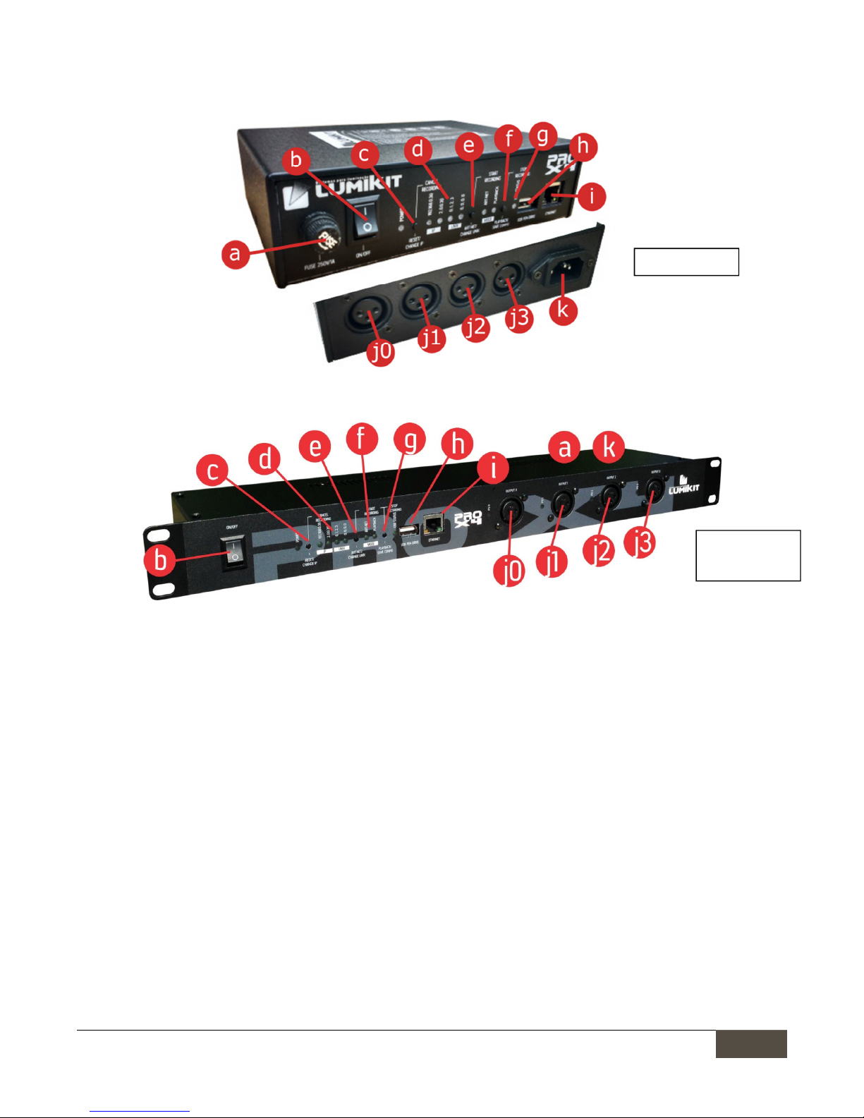
•
a: fuse;
o
Lumikit PRO X4 interface: 250V / 1A;
o
Lumikit PRO X4 interface: 250V / 3A (located in back panel);
•
b: ON/OFF key and LED on the right indicates if it is on;
•
c: “RESET/CHANGE IP” button for resetting, see chapter 5;
•
d: Indicator LEDs of the current configuration, if the LEDs are out, the interface is using other IP or other
Art-Net universes;
•
e: “ART-NET/CHANGE UNIV” button, sets the interface on Art-Net mode and if pressed together with the
“PLAYBACK/SAVE CONFIG” button, starts the record on Pen Drive;
•
f: “PLAYBACK/SAVE CONFIG” button, sets the interface in playback mode (reproduces programs recorded
in the Pen Drive), but only if valid programs are found in the Pen Drive;
•
g: “USB STATUS” LED, indicates if the connected Pen Drive is valid, if there are programs in the Pen Drive,
see chapter 6 for further details;
•
h: USB port to connect Pen Drives, see chapter 6 for further details;
•
i: Fast Ethernet network connector;
•
j0, j1, j2, j3: connectors with DMX signal, outputs 0, 1, 2 and 3, respectively, in RACK version there is a LED
next to each connector, denoting the functioning of related power supply;
•
k: Power connector, the interface power supply is BIVOLT (110 or 220V), in RACK model the connector is
located in the back part of the device;
Lumikit PRO X4
L
umikit PRO X4
RACK

Lumikit Sistemas para Iluminação
Lumikit Sistemas para IluminaçãoLumikit Sistemas para Iluminação
Lumikit Sistemas para Iluminação
| www.lumikit.com.br
7777
3.
3.3.
3. Configuring
Configuring Configuring
Configuring Lumikit PRO
Lumikit PRO Lumikit PRO
Lumikit PRO XXXX4444 interface
interfaceinterface
interface
It’s possible to configure the Art-Net universes that will be used in each of the 4 connectors and the interface
network settings, that’s why during the installation the necessary settings must be verified.
The interface comes with the following original factory settings:
• IP Address: 192.168.0.30 – Netmask: 255.255.255,0; (this IP is compatible with all Lumikit’s software);
• DMX Output 0=Art-Net Universe 0;Output 1=Art-Net Univ. 1; Output 2= Art-Net Univ. 2; Output 3= Art-Net
Univ. 4;
These settings can be easily changed as follows:
• Resetting the interface, at this moment other options can be chosen (see chapter 4);
• By Lumikit SHOW software, LUMIKIT LED or LUMIKIT Art-Net setting (shown below);
3.1 C
3.1 C3.1 C
3.1 Change the
hange the hange the
hange the interface
interface interface
interface IP
IP IP
IP address and universe
address and universeaddress and universe
address and universe via software
via softwarevia software
via software
Warning: in most of installations no change in interface setting is
Warning: in most of installations no change in interface setting is Warning: in most of installations no change in interface setting is
Warning: in most of installations no change in interface setting is necessary.
necessary.necessary.
necessary.
On Lumikit’s software, within the interface configuration (usually called by the button “Interfaces”), click the
button “Configure Art-Net interfaces” or directly in Lumikit Art-Net Config software, available in
http://www.lumikit.com.br/downloads/ArtNetConfig.zip, and this window will be shown:
On the list (1) will be shown the interfaces found on the network, If none appears, check the possible
communication problems (see the end of this manual) and then click “Search for interfaces on the network” (5)
In this list will be shown:
•
MAC address from the interface, this value cannot be changed;

Lumikit Sistemas para Iluminação
Lumikit Sistemas para IluminaçãoLumikit Sistemas para Iluminação
Lumikit Sistemas para Iluminação
| www.lumikit.com.br
8888
•
Name of the interface, this value cannot be changed;
•
IP address, it is the address which identifies the interface and allows the communication with the
computer. By default it is 192.168.0.30 for the first interface, in case more interfaces are used in the
same network, use 192.168.0.31, 192.168.0.32 and so on. It is important to remind that not all lightning
software allow the use of IP addresses that do not start with 2 (ex: 2.0.0.100) or with 10 (ex: 10.0.0.100).
In this case set the compatible IP addresses with the lightning software;
•
Number of universes, represent the number of DMX outputs in the interface;
•
Art-Net universes, show in sequence which Art-Net universes will be used by the DMX outputs;
When selecting an interface on the list (1), the subnet mask (http://pt.wikipedia.org/wiki/Subrede) will be shown
on the edit fields, use the mask according to the class from the used IP address, example: IP: 2.0.0.XXX, mask:
255.0.0.0; IP 192.168.0.XXX, mask: 255.255.255.0;
In these fields it is possible to set a new IP and a new subnet mask (2) besides defining which Art-Net universes
will be used by the DMX outputs (3);
After making the necessary changes, click “Reprogram interface” (4) and follow the given instructions:
With this procedure the reprogramming will be complete.
In case the interface does not be shown in the interface list enable the option “Use the software in BROADCAST
mode”, this way it will be sent a reprogramming package for the entire network, in this case, make sure that
only the interface you want to reprogram is connected to the network.
3.2
3.23.2
3.2 Configure the interface in software
Configure the interface in softwareConfigure the interface in software
Configure the interface in software
In t
In tIn t
In this manual will be shown how to configure the interface with the Lumikit SHOW
his manual will be shown how to configure the interface with the Lumikit SHOWhis manual will be shown how to configure the interface with the Lumikit SHOW
his manual will be shown how to configure the interface with the Lumikit SHOW software
softwaresoftware
software (same
(same (same
(same
procedure for Lumikit LED), the interface is compatible with other software and drivers since these are also
procedure for Lumikit LED), the interface is compatible with other software and drivers since these are also procedure for Lumikit LED), the interface is compatible with other software and drivers since these are also
procedure for Lumikit LED), the interface is compatible with other software and drivers since these are also

Lumikit Sistemas para Iluminação
Lumikit Sistemas para IluminaçãoLumikit Sistemas para Iluminação
Lumikit Sistemas para Iluminação
| www.lumikit.com.br
9999
compatible with the Art
compatible with the Artcompatible with the Art
compatible with the Art----Net Protocol, if the customer wants to configure the interface with other software or
Net Protocol, if the customer wants to configure the interface with other software or Net Protocol, if the customer wants to configure the interface with other software or
Net Protocol, if the customer wants to configure the interface with other software or
controller and do not know how
controller and do not know howcontroller and do not know how
controller and do not know how to make the settings, should contact the manufacturer to check how to do the
to make the settings, should contact the manufacturer to check how to do the to make the settings, should contact the manufacturer to check how to do the
to make the settings, should contact the manufacturer to check how to do the
required
required required
required settings to enable Art
settings to enable Artsettings to enable Art
settings to enable Art----Net.
Net.Net.
Net.
Before you begin the configuration make sure there is a connection with network cable between the network
card of the computer and the interface. Can also be used ethernet switches allowing more interfaces
connected to the same computer and/or access points/routers for wireless communication with the interface.
If you do not know which IP address is configured on the interface do the RESET of the interface (Chapter 5),
this procedure allows quick configuration of the IP address of the interface. By default the interface comes
standard with the IP 192.168.0.30, which is the IP compatible with all software from Lumikit.
There are two ways of configure the interface inside your software or controller:
• BROADCAST Mode
BROADCAST ModeBROADCAST Mode
BROADCAST Mode, indicated if there is only one interface in the network, or if all interfaces use the same
DMX universe, this mode is recommended for most of the installations. The BROADCAST mode will send the
Art-Net packages to all equipment connected in the network, because the destination IP used is not
interface IP, but 255.255.255.255 address;
• UNICAST Mode
UNICAST ModeUNICAST Mode
UNICAST Mode, indicated if the installation will have more than one interface in the same network and those
interfaces use different universes. In the UNICAST mode the Art-Net packages are sent individually to the
informed IP. This way the interfaces that will not use certain Art-Net package (because they are for another
DMX universe) don’t waste time processing unused packages.
3.2.1 BROADCAST mode
3.2.1 BROADCAST mode3.2.1 BROADCAST mode
3.2.1 BROADCAST mode
In Lumikit SHOW (ou Lumikit LED) software, do the following procedure:
a) Click in button “Interfaces” , in the top right-side;
b) In case there is any interface in the list, click in “Remove all”;
c) In displayed window ”Interface Configuration”, click in “Add”;
d) In displayed menu select “Art-Net Controller (Server)”:
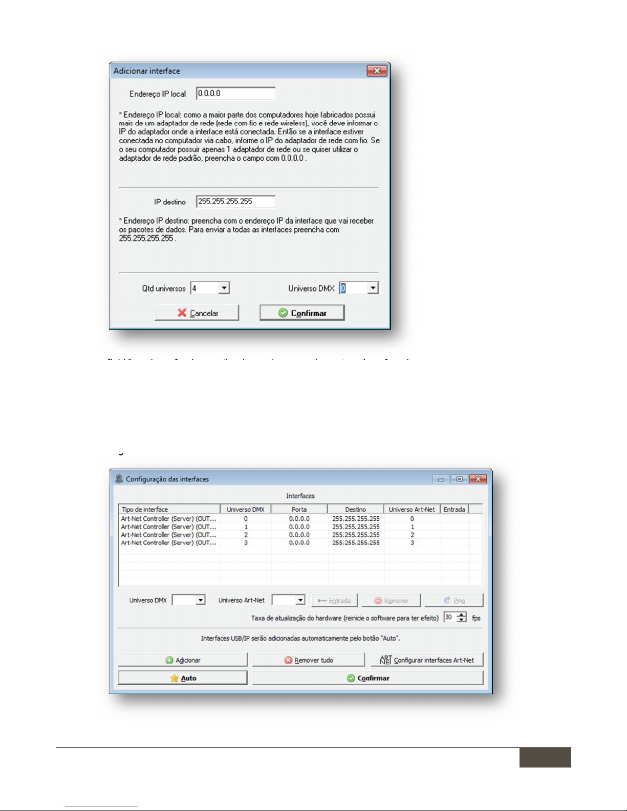
e) In new window, “Add interfaces”, let the “Local address” filled with 0.0.0.0 e the “destination IP“ with
255.255.255.255, this IP address send theArt-Net data package to all interfaces connected in the
Lumikit Sistemas para Iluminação
Lumikit Sistemas para IluminaçãoLumikit Sistemas para Iluminação
Lumikit Sistemas para Iluminação
| www.lumikit.com.br
10
1010
10
network:
f) In field “number of universes”, select 4, because the PRO X4 interface has 4 universes, if other setting is
used, for example, if interface is configured for only 1 universe, fill 1 in this field;
g) In field “DMX Universe”, fill 0,unless another initial DMX universe is used, anyway it also can be adjusted
again in window “Interface settings”;
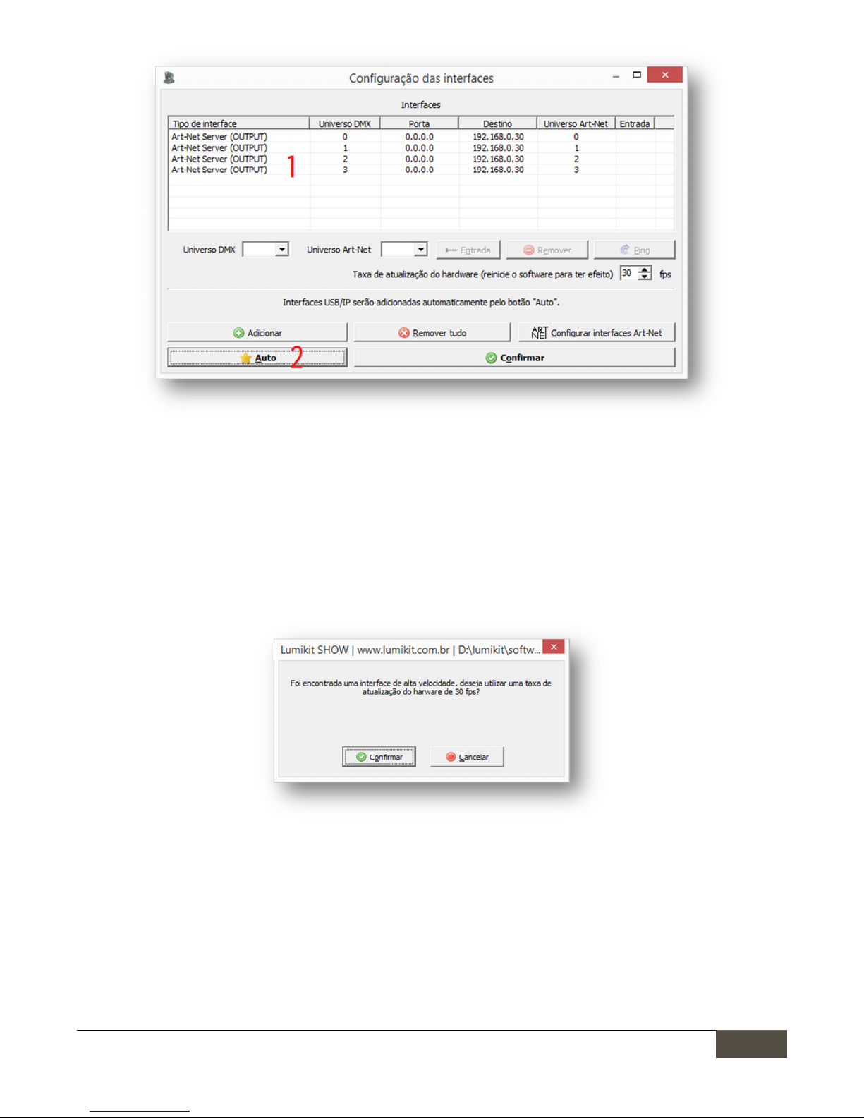
h) At this time the following setting can be viewed, when clicking “Confirm” and retuning to Lumikit SHOW
or Lumikit LED main window the interface Art-Net LED must be on without blink, with this the
configuration is finished:

Lumikit Sistemas para Iluminação
Lumikit Sistemas para IluminaçãoLumikit Sistemas para Iluminação
Lumikit Sistemas para Iluminação
| www.lumikit.com.br
11
1111
11
If the DMX update rate is low, it’s possible to increase the value in the field “Hardware update rate”, most of the
systems Works well with 30 fps (frames per second). The ideal is to test in practice, checking if the lighting
stops responding at some point, in this case it is better to use lower values.
3.2.2 UNICAST
3.2.2 UNICAST3.2.2 UNICAST
3.2.2 UNICAST Mode
ModeMode
Mode
Before starting
Before startingBefore starting
Before starting any configuration
any configurationany configuration
any configuration,
to
toto
to use the UNICAST mode check if the IP number of your board is in the same
use the UNICAST mode check if the IP number of your board is in the same use the UNICAST mode check if the IP number of your board is in the same
use the UNICAST mode check if the IP number of your board is in the same
network class as the IP number configured in the interface, for example
network class as the IP number configured in the interface, for examplenetwork class as the IP number configured in the interface, for example
network class as the IP number configured in the interface, for example:
: :
: if the
if theif the
if the interface
interface interface
interface IP
IP IP
IP is
is is
is 192.168.0.30,
192.168.0.30, 192.168.0.30,
192.168.0.30, your
your your
your
network card used to
network card used to network card used to
network card used to com
comcom
commmmmunica
unicaunica
unicate
tete
te with the
with the with the
with the interface
interface interface
interface must have an
must have an must have an
must have an IP
IPIP
IP 192.168.0.???
192.168.0.??? 192.168.0.???
192.168.0.??? ranging
rangingranging
ranging from
fromfrom
from 1
1 1
1 until
untiluntil
until 254
254 254
254
(exce
(exce(exce
(except
ptpt
pt 30).
30). 30).
30). Otherwise the communication with th
Otherwise the communication with thOtherwise the communication with th
Otherwise the communication with the interface will not be possible.
e interface will not be possible.e interface will not be possible.
e interface will not be possible.
The interface and the network card must have the same subnet mask number. Check the final chapters in the
manual to know the procedures of IP changing in your computer.
To check if the communication with the interface is working, simply enter, in the command prompt, the
command ping 192.168.0.30 ( or the IP address configured in the interface, if it was changed):
To use the UNICAST mode it’s importante that there is na answer from each network interface PING,in case this
is not possible, must be checked the settings of the network, routers (access point/ switches, as a last resort
try with another router model), interfaces the computer itself (probably the firewall or any antivirus is blocking
the communication). Remembering that if only 1 interface is used in the network, or if all interfaces use the
same Art-Net universe the BROADCAST mode may be used (chapter 3.2.1).
In case the net is properly configured and the PING answering, the setting of the interfaces inside the software
is simple, in software Lumikit SHOW (or Lumikit LED), do the following procedure:
a) Click in the button “Interfaces”, at the top right side;
b) In case there is any interface in the list, click in “Remove All”;
c) In displayed window “Interface settings”, click “Auto” (2) and after a few seconds the interfaces must be
automatically located:
Lumikit Sistemas para Iluminação
Lumikit Sistemas para IluminaçãoLumikit Sistemas para Iluminação
Lumikit Sistemas para Iluminação
| www.lumikit.com.br
12
1212
12
d) For each universe an Art-Net server will be created, see in the example above the list (1), when clicking
“OK” and returning to Lumikit SHOW or Lumikit LED main window the interface Art-Net LED must be on
without blink, with this the configuration is finished.
If the DMX update rate is low, may be suggested the increase of speed only use this if the network support
higher speed, the ideal is to test in practice, checking if the lighting stops responding at some point, in this case
it is better to use lower values:
3.3
3.3 3.3
3.3 Network
NetworkNetwork
Network speed
speed speed
speed (10Mpbs/100Mbps (Fast Ethernet))
(10Mpbs/100Mbps (Fast Ethernet))(10Mpbs/100Mbps (Fast Ethernet))
(10Mpbs/100Mbps (Fast Ethernet))
The interface hardware is compatible with 10 and 100Mbps networks, however there are 2 kinds of standard
for 100Mbps networks, which can cause incompatibility among network equipment from different
manufacturers. Lumikit chose to initiate the most common mode, but the customer can already have equipment
that are not compatible.
For that reason, from firmware version 1.1 (11) on, was created an option to force 10Mbps speed (compatible
with all network equipment) or 100Mbps. By default the interface Is configured to force 10Mbps speed, in case

Lumikit Sistemas para Iluminação
Lumikit Sistemas para IluminaçãoLumikit Sistemas para Iluminação
Lumikit Sistemas para Iluminação
| www.lumikit.com.br
13
1313
13
that speed is not enough for the customer we recommend to change the configuration to 100Mbps, in this case
the customer should make sure that the communication will work among all equipment.
To change between the settings keep the “ART-NET/CHANGE UNIV” button pressed while the interface is
connected, in this moment check the IP and UNIV LEDs:
• In case the IP and UNIV LEDs blink 5 times, the interface will work in 100Mpbs or 10Mpbs;
• In case the interface connect normally without the IP and UNIV LEDs blink, the interface will force
10Mbps speed in network communication.
4.
4.4.
4. Interface reset
Interface resetInterface reset
Interface reset
To restore the default settings, it can be done the interface resetting, to do this press and hold the
“RESET/CHANGE IP” button for at least 15 seconds when turning the interface on:
When in reset mode, it is possible to easily choose between the following IP addresses, by pressing the
“RESET/CHANGE IP” button:
•
IP address: 192.168.0.30 - Netmask: 255.255.255.0; (This IP is compatible with all software produced by
Lumikit);
•
IP address: 2.0.0.30 - Netmask: 255.0.0.0; (This IP is compatible with the majority of the software
produced by third parties);
And the following Art-Net universes in the DMX outputs, by pressing the ”ART-NET/CHANGE UNIV.” button:
•
DMX output 0=Art-Net Universe 0; Output1=Art-Net Univ. 1; Output 2=Art-Net Univ.2; Output 3=Art-Net
Univ.4;
•
DMX output 0=Art-Net Universe 0; Output1=Art-Net Univ. 0; Output 2=Art-Net Univ.0; Output 3=Art-Net
Univ.0; (Using this setting, DMX outputs will be in the first DMX universe, this way it will work as a DMX
splitter or buffer);
After finished the desired configuration press the “PLAYBACK/SAVE CONFIG.” button.
To choose other settings see chapter 3.
5.
5.5.
5. Interface connection
Interface connectionInterface connection
Interface connection
The Lumikit PRO X4 and Lumikit PRO X4 RACK interface connection is simple:

Lumikit Sistemas para Iluminação
Lumikit Sistemas para IluminaçãoLumikit Sistemas para Iluminação
Lumikit Sistemas para Iluminação
| www.lumikit.com.br
14
1414
14
•
The DMX outputs can be connected directly to the lighting devices which will be controlled, it can also be
used as a splitter or buffer for the DMX signal in case more than 32 lighting devices are connected in a
DMX output;
•
The power comes through a socket, the power supply works with 110 or 220V, it is not necessary to
select the tension, the power supply is automatic;
•
The Ethernet connection:
o
can be connected directly to the network card from the computer through a cable;
o
can be connected to a Ethernet switch in case of more interfaces or other devices in the same
network;
o
can be connected to an access point or router (wireless) allowing wireless communication;
To connect more than one interface on the same network, the IPs must be changed, below there is an example
of a connection of 2 or more interfaces on the same network:
Note that the second interface has a different IP address than the first interface, always use different IP
addresses.The computer is in the same network class as the interfaces (class C – 192.168.XXX.XXX).
6.
6.6.
6. Program recording in the P
Program recording in the PProgram recording in the P
Program recording in the Pen Drive
en Driveen Drive
en Drive
In the Lumikit PRO X4 interface it is possible to connect a Pen Drive in the USB port, this Pen Drive can be used
to record up to 20 programs, each program can have at most 30 minutes of Art-Net signal at 25 FPS.

Lumikit Sistemas para Iluminação
Lumikit Sistemas para IluminaçãoLumikit Sistemas para Iluminação
Lumikit Sistemas para Iluminação
| www.lumikit.com.br
15
1515
15
The interface has a “PEN DRIVE LED STATUS”, depending on the Pen Drive situation the LED can blink in different
ways:
• Off: no Pen Drive connected;
• On: Pen Drive ready for recording or playback;
• 1x : No program found: ready for recording;
• 2x : Pen Drive filled with valid program: cannot write more programs;
• 3x : Pen Drive full and no program found: cannot record or play;
• 4x : Invalid Pen Drive or invalid file format, format the Pen Drive using FAT or FAT32 file system;
6.1 Considerations on
6.1 Considerations on6.1 Considerations on
6.1 Considerations on Pen Drivers
Pen DriversPen Drivers
Pen Drivers
Depending on your Pen Drive model, the interface might reset or freeze for a few instants as soon as the
Depending on your Pen Drive model, the interface might reset or freeze for a few instants as soon as the Depending on your Pen Drive model, the interface might reset or freeze for a few instants as soon as the
Depending on your Pen Drive model, the interface might reset or freeze for a few instants as soon as the
Pen Drive is connected to the interface, this is normal, therefore it
Pen Drive is connected to the interface, this is normal, therefore itPen Drive is connected to the interface, this is normal, therefore it
Pen Drive is connected to the interface, this is normal, therefore it is recommended to connect the Pen Drive
is recommended to connect the Pen Drive is recommended to connect the Pen Drive
is recommended to connect the Pen Drive
when the interface is switched off.
when the interface is switched off.when the interface is switched off.
when the interface is switched off.
In some cases the Pen Drive might not be compatible with the interface, some minimum requirements for the
Pen Drive to work correctly:
•
The Pen Drive must be in the FAT or FAT32 format, other formats are not compatible;
•
To use the Pen Drive for recording, it must have high transfer rate. Low speed Pen Drives will freeze the
interface during the recording process. To measure the speed of the Pen Drive, an specific software
such as the USBFlashSpeed can be used (available on
http://www.lumikit.com.br/downloads/USBTest.zip), the minimum recommended is 6MB/s with 4KB
blocks:
Examples of Pen Drive models that have a great performance: JetFlash Transcend, Corsair Slider.
Even though the quoted models being from USB 3.0 format, and the interface works with USB 2.0 format, USB
3.0 models can be used normally.
6.2 File structure
6.2 File structure 6.2 File structure
6.2 File structure inside a
inside ainside a
inside a Pen Drive
Pen DrivePen Drive
Pen Drive
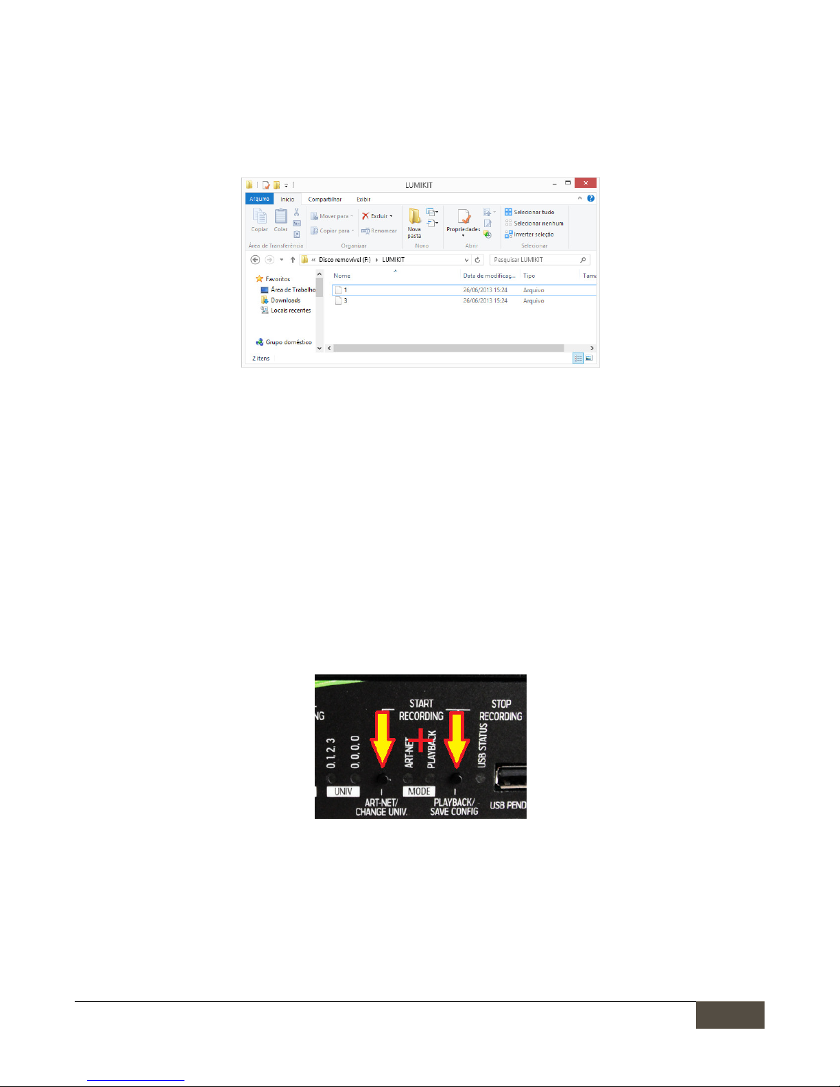
When connecting a Pen Drive to the interface, it will be checked if the file system is valid (FAT or FAT32), after
the verification and if the folder does not already exists, a new folder named LUMIKIT will be created. In this
folder all the programs recorded by the interface will be stored.
Lumikit Sistemas para Iluminação
Lumikit Sistemas para IluminaçãoLumikit Sistemas para Iluminação
Lumikit Sistemas para Iluminação
| www.lumikit.com.br
16
1616
16
The folder can store up to 20 files, this files will be named with one character indicating the corresponding
program, the names are: : “0”, “1”, “2”, “3”, “4”, “5”, “6”, “7”, “8”, “9”, “A”, “B”, “C”, “D”, “E”, “F”, “G”, “H”, “I” e “J”. File “0”
corresponds to the first program, file “1” to the second and so on, until file “J”, which corresponds to the
twentieth program
This Pen Drive can also be opened in Windows Explorer or in MAC’s Finder:
In the example above, the Pen Drive has 2 programs; the file “1” corresponds to the program in position “2” and
the program “3” corresponds to the program “4”.
It is possible to copy the programs to another Pen Drive and also delete the programs.
Every minute of recording corresponds to approximately 3MB of data. The maximum recording time is 30
minutes, in this case the file will have approximately 90MB. Since the interface supports up to 20 programs, a
2GB Pen Drive is enough to store all programs.
6.3
6.3 6.3
6.3 Recording
RecordingRecording
Recording a program in the Pen Drive
a program in the Pen Drivea program in the Pen Drive
a program in the Pen Drive
If the Pen Drive connected is valid, has enough storage space, less than 20 programs and the interface is
receiving Art-Net signal, it is possible to record a new program, to do this, press the button “ART-NET/CHANGE
UNIV.” and the button “PLAYBACK/SAVE CONFIG.” at the same time:
After the beginning of the recording, it is possible to end it through the button “PLAYBACK/SAVE CONFIG”, in this
case the program will be recorded in the Pen Drive or the recording can be canceled through the button
“RESET/CHANGE IP”, in this case the program will not be recorded in the Pen Drive. The maximum recording time
is 30 minutes, after that the process will be automatically ended.
The recording can also be made through the interface’s remote control app, check the next chapters of this
manual.

Lumikit Sistemas para Iluminação
Lumikit Sistemas para IluminaçãoLumikit Sistemas para Iluminação
Lumikit Sistemas para Iluminação
| www.lumikit.com.br
17
1717
17
6.4 Reproducing programs from the
6.4 Reproducing programs from the6.4 Reproducing programs from the
6.4 Reproducing programs from the Pen Drive
Pen DrivePen Drive
Pen Drive
If the connected Pen Drive is valid and has valid programs, it is possible to make the reproduction of these
programs by pressing the button “PLAYBACK/SAVE CONFIG”, if there is more than one program inside the Pen
Drive, the next program will be reproduced by pressing the button “PLAYBACK/SAVE CONFIG” again.
The program reproduction can be also be made through the remote control app, check the next chapters of this
manual.
6.5
6.5 6.5
6.5 Deleting programs from the Pen Drive
Deleting programs from the Pen DriveDeleting programs from the Pen Drive
Deleting programs from the Pen Drive
It is not possible to delete a program directly through the interface, only by using the remote control app or by
disconnecting the Pen Drive from the interface e connecting to a computer; the program can be deleted through
Windows Explorer or MAC’s Finder directly from the LUMIKIT folder inside the Pen Drive.

Lumikit Sistemas para Iluminação
Lumikit Sistemas para IluminaçãoLumikit Sistemas para Iluminação
Lumikit Sistemas para Iluminação
| www.lumikit.com.br
18
1818
18
7.
7.7.
7. Firmware update
Firmware updateFirmware update
Firmware update
Using a Pen Drive connected to the USB port of the interface, the firmware update can be made.
The latest firmware version of the Lumikit PRO X4 interface can be found in the site:
http://www.lumikit.com.br/interface-dmx-lumikit-pro-x4 or directly through this link
http://www.lumikit.com.br/firmware/interface-lumikit-pro-x4/, where all versions are available.
To do the update:
• copy the file named lkprox4.cry to the main folder (\) of the Pen Drive, keep in mind that the Pen Drive
must be on the FAT or FAT32 format;
• turn off the interface, connect the Pen Drive to the interface;
• press and hold the “PLAYBACK/SAVE CONFIG” button, turn on the interface;
• if the lkprox4.cry file is found on the Pen Drive, the “USB STATUS” LED will be on for approximately 10 to
20 seconds, which is the needed time for updating the firmware;
• after the update, confirm the firmware version on Lumikit’s software, the version is shown after the
interface identification, in the example, LUMIKIT PRO X4 version 10 (V10):
Do not attempt to change the lkprox4.cry file, do not use files from other suppliers under the risk of
Do not attempt to change the lkprox4.cry file, do not use files from other suppliers under the risk of Do not attempt to change the lkprox4.cry file, do not use files from other suppliers under the risk of
Do not attempt to change the lkprox4.cry file, do not use files from other suppliers under the risk of
“bricking” the interface, this issue will not be covered by the warranty.
“bricking” the interface, this issue will not be covered by the warranty.“bricking” the interface, this issue will not be covered by the warranty.
“bricking” the interface, this issue will not be covered by the warranty.
8.
8.8.
8.
Remote control for Android and iOS
Remote control for Android and iOSRemote control for Android and iOS
Remote control for Android and iOS
Through the Lumikit PRO X4 RC app, available on the App Store (for iOS 8 or superior) and Google Play (for
Android 4.0 or superior) it is possible to control remotely the Lumikit PRO X4 interface, as long as the interface
and the cellphone or tablet are connected to the same Wi-Fi network as the interface. Tap over the “PRO X4”
logo in the upper corner the available interfaces on the network will be shown:

Lumikit Sistemas para Iluminação
Lumikit Sistemas para IluminaçãoLumikit Sistemas para Iluminação
Lumikit Sistemas para Iluminação
| www.lumikit.com.br
19
1919
19
When selecting the interface, options are shown according to the selected mode and available functions:
If there is no Pen Drive connected, or the Pen Drive has some issue (invalid
format) only the Art-Net mode may be used:
In case there is a valid Pen Drive connected to the interface, the programs in
the Pen Drive will be shown, at the upper corner it is possible to see the option
to delete programs ( ) from the Pen Drive and an option to make a new
recording ().
When selecting the recording option, total recording time will be shown, keep
in mind that it is possible to cancel the recording process, in this case nothing
will be recorded or stop the recording, this way what was recorded will be in
the Pen Drive. The recording ends automatically in 30 minutes.
When selecting the option to delete a program, all programs that can be
deleted from the Pen Drive will be shown, when selecting a program, it will be
deleted permanently from the Pen Drive.

Lumikit Sistemas para Iluminação
Lumikit Sistemas para IluminaçãoLumikit Sistemas para Iluminação
Lumikit Sistemas para Iluminação
| www.lumikit.com.br
20
2020
20
If the interface does not appear on the list, check the end of this manual for possible network problems, it is
more likely that the cellphone or tablet is in a different network than the interface.
Even if the interface is not shown in the list it is possible to use the BROADCAST mode, this mode send the
commands to all network. In BROADCAST mode, it is not possible to record or delete programs in the Pen Drive.
9.
9.9.
9. Identification label
Identification labelIdentification label
Identification label
The interface comes with an identification label, below is a copy in case the label is illegible or has worn off.
9999.1
.1 .1
.1 Lumikit PRO X4
Lumikit PRO X4Lumikit PRO X4
Lumikit PRO X4

Lumikit Sistemas para Iluminação
Lumikit Sistemas para IluminaçãoLumikit Sistemas para Iluminação
Lumikit Sistemas para Iluminação
| www.lumikit.com.br
21
2121
21
9.2
9.29.2
9.2 Lumikit PRO X4 RACK
Lumikit PRO X4 RACKLumikit PRO X4 RACK
Lumikit PRO X4 RACK
10.
10.10.
10. IIIInterface i
nterface interface i
nterface iso
soso
solation
lationlation
lation
All Lumikit interfaces have i
All Lumikit interfaces have iAll Lumikit interfaces have i
All Lumikit interfaces have iso
soso
solation with
lation with lation with
lation with an opto
an optoan opto
an opto----coupler
coupler coupler
coupler in
in in
in the logic circuit output.
the logic circuit output.the logic circuit output.
the logic circuit output.
10.1 Lumikit PRO X4
10.1 Lumikit PRO X410.1 Lumikit PRO X4
10.1 Lumikit PRO X4
The interface has an isolation of 1500 Vrms with the network cable, according to standards, this isolation is
made through the transformer within the RJ45 connector.
Each output has an opto-coupler with the logic circuit, 2500 Vrms.
The DMX outputs have a galvanic isolation of 1000 Vrms (pin 1 from connector 0 and 1 is isolated from DMX
outputs 2 and 3).
10.2
10.210.2
10.2 Lumikit PRO X4 RACK
Lumikit PRO X4 RACKLumikit PRO X4 RACK
Lumikit PRO X4 RACK

Lumikit Sistemas para Iluminação
Lumikit Sistemas para IluminaçãoLumikit Sistemas para Iluminação
Lumikit Sistemas para Iluminação
| www.lumikit.com.br
22
2222
22
The interface has an isolation of 1500 Vrms with the network cable, according to standards, this isolation is
made through the transformer within the RJ45 connector. Each output has an opto-coupler with the logic
circuit, 2500 Vrms.
The DMX outputs have a galvanic insulation of 1000 Vrms (pin 1 from connector 0 and 1 is insulated from DMX
outputs 2 and 3).
10
1010
10....3 Grounding
3 Grounding3 Grounding
3 Grounding
It is recommended to use installations with grounding.
The
The The
The GROUND pin of the
GROUND pin of the GROUND pin of the
GROUND pin of the power supply
power supply power supply
power supply connector
connectorconnector
connector is connected to the interface housing.
is connected to the interface housing.is connected to the interface housing.
is connected to the interface housing.
Problems that might be caused by the lack of grounding:
•
interface disconnects randomly;
•
devices can receive random DMX signals;
•
LOW SECURITY TO THE OPERATOR: RISK OF ELETRIC SHOCK!
See more about grounding on the internet: http://pt.wikipedia.org/wiki/Terra_(eletricidade)

Lumikit Sistemas para Iluminação
Lumikit Sistemas para IluminaçãoLumikit Sistemas para Iluminação
Lumikit Sistemas para Iluminação
| www.lumikit.com.br
23
2323
23
11.
11.11.
11. Cont
ContCont
Contents of the packaging
ents of the packagingents of the packaging
ents of the packaging
•
Lumikit PRO X4 or Lumikit PRO X4 RACK interface;
•
Power supply cable;
•
Straight network cable;
•
Instruction booklet;
12.
12.12.
12. Ma
MaMa
Maintenance
intenanceintenance
intenance
There are no internal components that can be replaced by the client. Only the DMX outputs’ CIs can be replaced
by technician. In case there is a problem, we recommend getting in touch with Lumikit for the maintenance
procedures.
The components are extremely sensitive to electrostatic energy. Use proper protection.
13.
13.13.
13. Cleaning
CleaningCleaning
Cleaning
When cleaning the interface, remember to disconnect it from the DMX line, the computer and the electric
network.
The interface can be cleaned with a cloth slightly moistened.
Wait until is completely dry to connect the cables again.
14.
14.14.
14. Warranty
WarrantyWarranty
Warranty
The Lumikit PRO X4 and PRO X4 RACK interface has a 12 month warranty. The network cable and the integrated
output circuits are not covered by the warranty, since they depend on client’s installation. An overload on the
electrical system (lightning, short-circuits and other issues) that may damage the interface is not covered by
the warranty as well.
Attention to further consideration on the warranty:
The USB port in this interface was projected only for Pen Drivers usage,
The USB port in this interface was projected only for Pen Drivers usage, The USB port in this interface was projected only for Pen Drivers usage,
The USB port in this interface was projected only for Pen Drivers usage, CONNECTING ANY OTHER DEVICE IN
CONNECTING ANY OTHER DEVICE IN CONNECTING ANY OTHER DEVICE IN
CONNECTING ANY OTHER DEVICE IN
THIS PORT THAT IS NOT A PEN DRIVE WILL DAMAGE THE INTERFACE, THIS DAMAGES WILL NOT BE COVERED BY THE
THIS PORT THAT IS NOT A PEN DRIVE WILL DAMAGE THE INTERFACE, THIS DAMAGES WILL NOT BE COVERED BY THE THIS PORT THAT IS NOT A PEN DRIVE WILL DAMAGE THE INTERFACE, THIS DAMAGES WILL NOT BE COVERED BY THE
THIS PORT THAT IS NOT A PEN DRIVE WILL DAMAGE THE INTERFACE, THIS DAMAGES WILL NOT BE COVERED BY THE
WARRANTY,
WARRANTY,WARRANTY,
WARRANTY, more information in chapter 6.
more information in chapter 6.more information in chapter 6.
more information in chapter 6.
Do not attempt to change the lkprox4.cry file, do not use files from
Do not attempt to change the lkprox4.cry file, do not use files fromDo not attempt to change the lkprox4.cry file, do not use files from
Do not attempt to change the lkprox4.cry file, do not use files from other suppliers under the risk of
other suppliers under the risk of other suppliers under the risk of
other suppliers under the risk of
“bricking” the interface, THIS ISSUE WILL NOT BE COVERED BY THE WARRANTY, more information in chapter 7.
“bricking” the interface, THIS ISSUE WILL NOT BE COVERED BY THE WARRANTY, more information in chapter 7.“bricking” the interface, THIS ISSUE WILL NOT BE COVERED BY THE WARRANTY, more information in chapter 7.
“bricking” the interface, THIS ISSUE WILL NOT BE COVERED BY THE WARRANTY, more information in chapter 7.

Lumikit Sistemas para Iluminação
Lumikit Sistemas para IluminaçãoLumikit Sistemas para Iluminação
Lumikit Sistemas para Iluminação
| www.lumikit.com.br
24
2424
24
15.
15.15.
15. Changing the
Changing theChanging the
Changing the IP address
IP addressIP address
IP address / Windows 7
/ Windows 7/ Windows 7
/ Windows 7 e 8
e 8e 8
e 8
To establish the initial communication with the interface, configure your computer’s network adapter to the IP
192.168.0.30, because this IP is from the same class as the default manufacture IP 192.168.0.30, below there is a
step by step tutorial on how to make the IP configuration on Windows 7 e 8:
In Windows 7, click on start or in Windows 8 on the home screen, search for “Control Panel”; Click “Network and Internet”:
Click “Network and Sharing Center”:
On the left side, click “Change adapter settings”:
Search for “Local Area Connection”, click with the right mouse button and select “Properties”:
Select “Internet Protocol Version 4 (TCP/IPv4)”, e click in properties:
Select “Use the following IP address:”; Complete the field “IP address:” with “192.168.0.1”; Complete the field “Subnet mask:” with “255.255.255.0”:
Confirm all with the “OK” button;
When in “Network Connection”, deactivate all the other connections so the software does not try to connect through another door the interface is not physically
connected to.

Lumikit Sistemas para Iluminação
Lumikit Sistemas para IluminaçãoLumikit Sistemas para Iluminação
Lumikit Sistemas para Iluminação
| www.lumikit.com.br
25
2525
25
In case you need to use another network adapter with the interface, report within the software in which network card the connection should be made, by informing
the adapter’s IP.
16.
16.16.
16. Changing the IP address
Changing the IP addressChanging the IP address
Changing the IP address / MACOSX
/ MACOSX/ MACOSX
/ MACOSX
To establish the initial communication with the interface, configure your computer’s network adapter to the IP
192.168.0.30, because this IP is from the same class as the default manufacture IP 192.168.0.30, below there is a
step by step tutorial on how to make the IP configuration on MACOSX:
Access the “System Preferences” ;
Click in “Network”:
Select “Ethernet”; complete the field “IP Address:” with “192.168.0.1” and “Subnet mask:” with “255.255.255.0”:
Type “ping 192.168.0.30” in the Terminal to check if the communication is working,
Turn off the Air-Port if a communication with the interface is not established.

Lumikit Sistemas para Iluminação
Lumikit Sistemas para IluminaçãoLumikit Sistemas para Iluminação
Lumikit Sistemas para Iluminação
| www.lumikit.com.br
26
2626
26
17.
17.17.
17. Problem
ProblemProblem
Problems and solutions
s and solutionss and solutions
s and solutions
Below, a list of problems and possible solutions:
Q: When I click “Auto” on the interface configuration on Lumikit software, the interface does not appear, the interface is on.
A: Check if the Lumikit PRO X4 / RACK interface is responding, by doing a PING to the interface’s IP. If the interface does not
respond to the ping, it will not be recognized by the software as well. This problem might be caused by the following
factors:
- The network cable is incompatible, in this case, none of the LED’s from the interface’s network connector will be on or
blinking: a straight network cable is provided, if your computer is older, you will need a crossover cable, it can be found in
informatics store;
- The computer or interface is using incompatible IP addresses? In case you do not have lots of experience with computer
network, use the IP 192.168.0.1 on the computer and the IP 192.168.0.30 on the interface or ask for help from someone with
more experience on the subject;
- Use fixed IP, even when using a router with DHCP server, sometimes the computer cannot receive the return package
from the interface, in this case use a fixed IP.
- Turn off other network adapters;
- If using WINDOWS check the firewall, initially turn the firewall off completely, if it works, create a rule for Lumikit
software.
Q: The interface does not turn on.
A: In case the interface does not turn on, check the fuse, it should be a 250V / 1A fuse for Lumikit PRO X4 and 250V / 3A for
Lumikit PRO X4 RACK, disconnect the interface from the electric network to avoid electric shocks while the fuse is being
verified. Check if the interface is connected in wrong tension, also check the power supply.
Q: One or more DMX outputs are not working.
A: Check if the DMX-Art-net universes are configured correctly, if they are, check your DMX cables, the DMX output circuit
might have burned, get in touch with support for more information about maintenance.
Q: The DMX devices receive random signal.
A: Check your DMX cables, their length, avoid piling up the cables, you will get interference, also check the DMX devices in
your DMX line. Use a terminator resistor on the last DMX device, this resistor has 1/2W and 120 ohms, it must be
connected between the pin 2 and 3 from the XLR – Canon connector.
Q: The interface is found by the “Auto” button, but does not receive Art-Net packages from the software.
A: The interface is probably in another network class, different from the network class from the network adapter. Always
use the same network class between the interface and the computer. Use a fixed IP on the computer.
Check the FAQ in the site, there are always updated tips: http://www.lumikit.com.br/faq
 Loading...