

Lumiax Shine series, Shine 05, Shine 03 User Manual
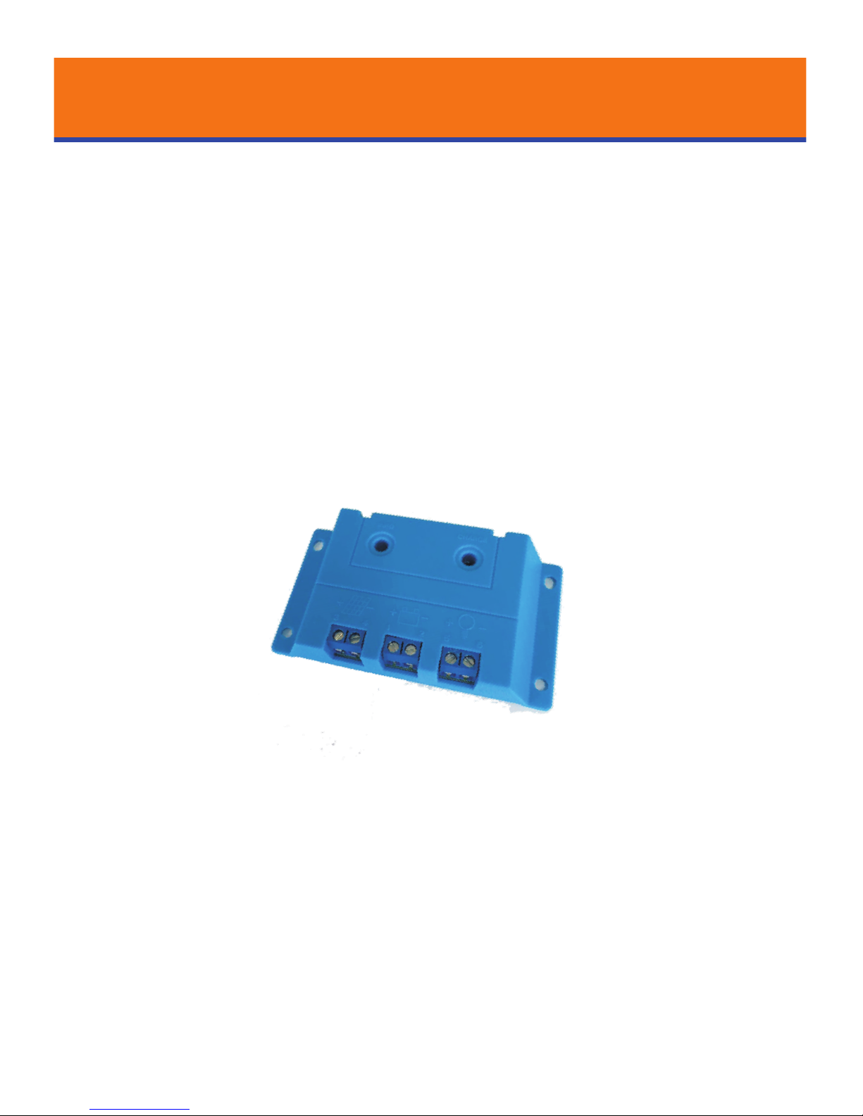
Shine series
Solar Charge Controller
3A/5A 12V
User Manual
www.lu m iax. c om
Lumiax
Magic your solar life
User Manual_Shine series_HE
CE, Rohs, ISO9001:2015
Subject to change without notice!
Shine series solar controller is especially for solar home
system, with better cost-effective.
It comes with a number of outstanding features,
such as:
Low cost and high reliability design
Clear readable display of charge/discharge and error
description
Four stage charge way: fast, boost, equalization, float
Full automatic electronic protect function
12V sys tem voltage
Tempera ture compensatio n
Solar charge controller Shine03/05 User Manual
INFO CHARGE
18
49
90
Page 1 of 2 Pages
This manual gives important recommendations for installing and using and so on. Read it carefully in your own interest please.
Dear Clients,
Thanks for selecting the Shine series solar controller. Please take the time to read this user manual, this will help you to make full
use of many advantages the controller can provide your solar system.
1.Description of Function
2.Safety instructions and waiver of liability
2.1 Safety
①The solar charge controller may only be used in PV
systems in accordance with this user manual and the
specifications of other modules manufacturers. No energy
source other than a solar generator may be connected to
the solar charge controller.
②Batteries store a large amount of energy, never short
circuit a battery under all circumstances. We strongly
recommend connecting a fuse directly to the battery to
protect any short circuit at the battery wiring.
2.2
③Batteries can produce flammable gases. Avoid making
sparks, using fire or any naked flame. Make sure that the
battery room is ventilated.
④Avoid touching or short circuiting wires or terminals. Be
aware that the voltages on special terminals or wires can
be as much as twice the battery voltage. Use isolated
tools, stand on dry ground, and keep your hands dry.
⑤Keep children away from batteries and the charge
controller.
Liability Exclusion
The manufacturer shall not be liable for damages,
especially on the battery, caused by use other than as
intended or as mentioned in this manual or if the
recommendations of the battery manufacturer are
neglected. The manufacturer shall not be liable if there has
been service or repair carried out by any unauthorized
person, unusual use, wrong installation, or bad system
design.
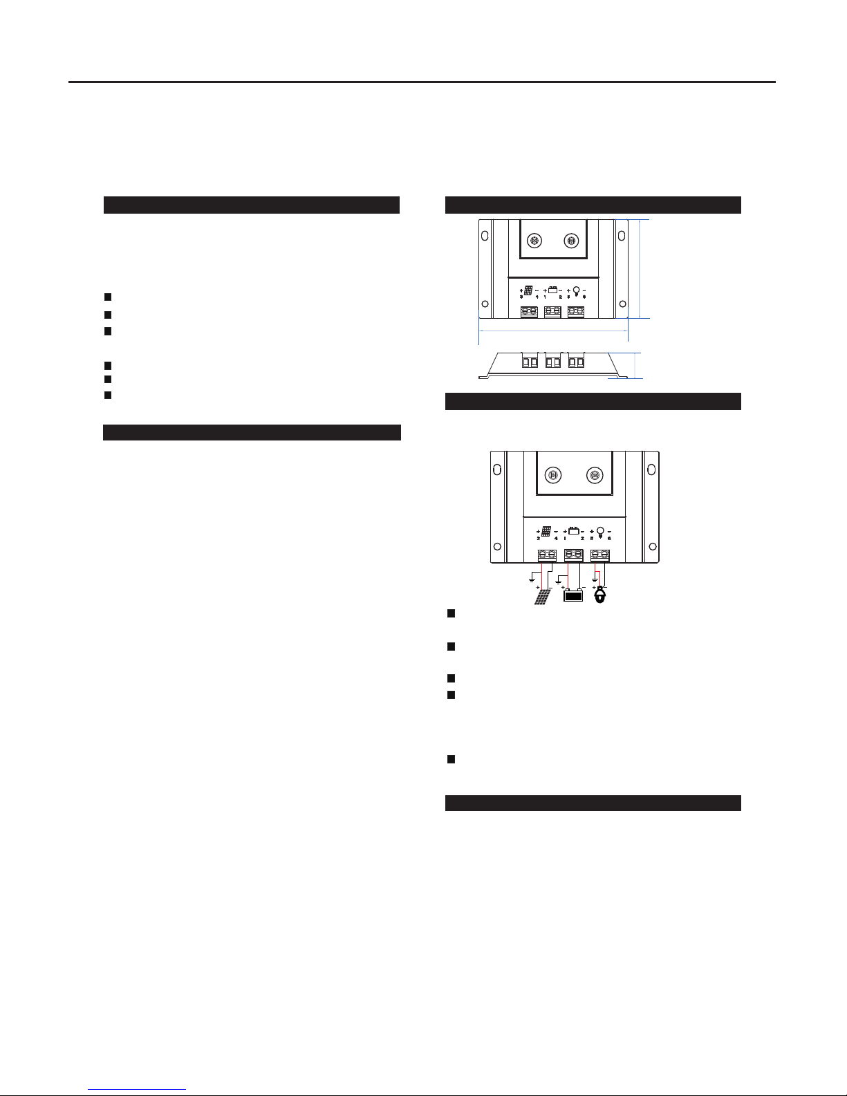
3.Dimensions
4.Installation
The following diagrams provide an overview of the
connections and the proper order.
To avoid any voltage on the wires, first connect the wire to
the controller, then to the battery, panel or load.
Make sure the wire length between battery and controller
is as short as possible.
Recommended minimum wire size: 1.5 mm².
Be aware that the positive terminal of Sshine are
connected together and therefore have the same
electrical potential. If any grounding is required, always do
this on the positive wires.
Connecting capacitive load may trigger short circuit
protection.
5.Starting up the controller
5.1S
e
l
f Test
As soon as the co
nt
roll
er i
s su
p
p
lied wit
h ba
tt
e
r
y, it
st
art
s a se
l
f test ro
utine
. The
n the d
is
p
lay c
h
an
g
es to
nor
m
al o
pe
r
a
tion
.
5.2System Volt
ag
e
Th
e c
ontr
olle
r i
s 12
V s
y
s
t
em v
ol
tag
e. A
s so
on a
s t
he
b
at
t
ery voltag
e at th
e tim
e of s
t
art-up i
s with
i
n 1
0V t
o 16V,
th
e c
ontr
olle
r i
mpl
ie
s a 12
V s
y
st
em.
If t
he bat
ter
y volta
g
e is n
ot w
ithin th
e nor
m
al o
p
e
r
a
ting
r
a
ng a
t sta
rt-u
p
, a sta
tus dis
pl
ay a
cco
rd
in
g to t
he s
e
ction
E
r
r
or d
esc
rip
ti
on o
c
c
ur.
5
.3
Battery T
yp
e
T
he c
on
tr
olle
r a
pplie
s to Liq
ui
d batt
ery
.
INFO CHARG E
①
②
③
④
⑤
⑥
 Loading...