

Page 1
ww w.l umi ax .co m
Lumia x
Ma gic y ou r sol ar l ife
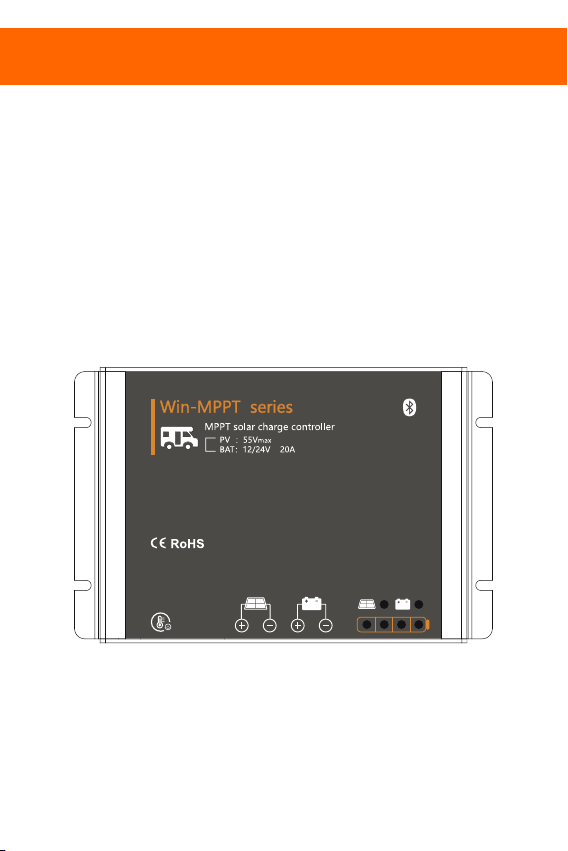
Win series
MPPT Solar Controller
12/24V, 260/520W
User Manual
User Manual_Wi n ser ies _JK
CE, Rohs , ISO 900 1:2015
Subject to ch ang e wit hou t not ice !
Page 2

Contents
Safety instructions and waiver of liability .
1 ...2
Safety Instructions .
1.1 ...2
1.2 Liability Exclusion ... ...2
2 ...................................................................................................................................................................
Pruduct Overview
2.1 MPPT
2.2 MPPT-Four Charging Stage
Dimensions
3 .....................................................................................................................................................................................5
Structure & Accessory
4 ...............................................................................................................................................................6
Installation
5 ......................................................................................................................................................................................7
5.1 Installation Notes
5.2 Mounting Location Requirements. ................................. ...7
5.3 Wiring Specifications................................................................................................................................................................8
5.4 Connection ..... .........................................8
5.5 Grounding.....................................................................................................................................................................................8
6 Bluetooth................................................................ ................................................. ...... .....................................9
6.1 Bluetooth Communication......... ...........................................................................................................................................9
6.2 Battery Type...................................... .........................................................................................................................................9
7 LED indications, Protections and Maintenance...........................................................................................................10
7.1 Led Display..................................... .......................................................................................................................................... 0
Faults & Alarms
7.2 .......................... ............................................................................................................................................10
7.3 Protection...................................... ...........................................................................................................................................11
7.4 Maintenance ......................................11
8 Technical Data ...................................................................
........................................................................................................................................................... ......
........................................................................................................................................................... ......
.. ...3
.............................................................................................................................................................................................3
............... ......................................................................................................................
........................................................................................................................................
.............................................................................................. ............12
...................................................................................................................................................4
.......................................................................................................................................................................7
..
....................................... .............................................................................
................................. ..................................................................
..
..
..
.. 1
..
....................... ....
1
Page 3
Dear Clients,
Thanks for selecting the Win series solar controller.
Please take the time to read this user manual, this will help you to make full use of many advantages the
controller can provide your solar system.
using and so on. Read it carefully in your own interest and pay attention to the safety recommendations in
it please.
This manual gives important recommendations for installing and
1, Safety instructio ns and waiver of liability
1.1 Safety Instructions
WARNING: Danger of explosion from sparking.
Danger of electric shock.
CAUTION:Indicates a critical procedure for safe and proper operation of the
controller.
1)There are no user serviceable parts inside the controller. Do not disassemble
or attempt to repair the controller.
2)Keep the children away from batteries and the charge controller.
(1)
It is advised to read this manual carefully before the product is installed and put into use.
There are no user serviceable parts inside the controller. Do not disassemble or attempt to repair the
(2)
controller.
(3)Install the controller at well ventilated places, the controller's heat sink will be very hot during operation.
(4)Refer to the specifications provided by the manufacturer of the battery to ensure that the battery is suitable
for use with this product. The battery manufacturer's safety instructions should always be observed.
(5)Protect the solar modules from incident light during installation, e.g. cover them.
(6)Ensure that the connection cables are provided with fuses or circuit breakers.
(7)Please make sure to switch off all connections of the PV array and the fuse/breakers which close to the
battery before the controller installation and adjustment.
(8)Power connections must remain tight to avoid excessive heating from the loose connection.
(9)Do not open the controller casing. Only the terminal cover may be removed by a technical professional for
installation.
1.2 Liability Exclu sio n
The m anufa cture r shal l not be li able fo r damag es, esp ecial ly on the b atte ry, cau sed by u se othe r
tha n as inte nded or a s menti oned in t his man ual or if t he rec ommen datio ns of the ba tter y
man ufact urer ar e negl ected . The ma nufac turer s hall no t be lia ble if th ere has b een ser vice o r
rep air ca rried o ut by any u nauth orize d perso n, unus ual use , wrong i nsta llati on, or ba d syst em
des ign.
2
Page 4

2,Overview
Win series solar controller is based on an advanced maximum power point tracking (MPPT) technology
developed, dedicated to the solar system, the controller conversion efficiency up to 98%.
The controller can rapidly track the maximum power point(MPP) of PV array to obtain the maximum
energy of the panel, especially in case of a clouded sky, when light intensity is changing continuously, an
ultra fast MPPT controller will improve energy harvest by up to 30% compared to PWM charge controllers.
2.1 Outstanding features
Innovative Max Power Point Tracking(MPPT) technology, tracking efficiency >99.9%
Full digital technology, high charge conversion efficiency up to 98%
LED indicator for easy to read charging state and battery information
12/24V automatic recognition
Liquid, Gel, AGM and Lithium battery for selection
The separate ports for remote temperature sensor, make battery temperature compensation more
accurate
Four stages charge way: MPPT, boost, equalization, float
Automatic over-temperature power reduction function
Dual automatic restriction function when exceeding rated charging power and charging current
Android APP version for Bluetooth communication
Common negative design
Perfect EMC & thermal design
Full automatic electronic protect function
2.2 MPPT
MPPT profile
The full name of the MPPT is maximum power point tracking. It is an advanced charging way which could
detect the real-time power of the solar Modulel and the maximum point of the I-V curve that make the
highest battery charging efficiency.
Current Boost
Under most conditions, MPPT technology will "boost" the solar charge current.
MPPT Charging:Power Into the controller (Pmax)=Power out of the controller (Pout)
Iin x Vmp= Iout x Vout
* Assuming 100% efficiency. Actually, the losses in wiring and conversion exist.
If the solar module's maximum power voltage (Vmp) is greater than the battery voltage, it follows that the
battery current must be proportionally greater than the solar input current so that input and output power are
balanced. The greater the difference between the Vmp and battery voltage, the greater the current boost.
Current boost can be substantial in systems where the solar array is of a higher nominal voltage than the
battery as described in the next section.
High Voltage Strings and Grid-Tie Modules
Another benefit of MPPT technology is the ability to charge batteries with solar arrays of higher nominal
voltages. For example, a 12 Volt battery bank may be charged with a 12-, 24-, 36-, or 48-Volt nominal off-grid
solar array. Grid-tie solar modules may also be used as long as the solar array open circuit voltage (Voc) rating
will not exceed the maximum input voltage rating at worst-case (coldest) module temperature. The solar module
documentation should provide Voc vs. temperature data.
Higher solar input voltage results in lower solar input current for a given input power. High voltage solar input
strings allow for smaller gauge solar wiring. This is especially helpful and economical for systems with long wiring
runs between the controller and the solar array.
3
Page 5

An Advantage Over Traditional Controllers
Traditional controllers connect the solar module directly to the battery when recharging. This requires
that the solar module operate in a voltage range that is usually below the module's Vmp. In a 12 Volt
system for example, the battery voltage may range from 10.8-15 Vdc,but the module's Vmp is typically
around 16 or 17V.
Because traditional controllers do not always operate at the Vmp of the solar array, energy is wasted that
could otherwise be used to charge the battery and power system loads. The greater the difference
between battery voltage and the Vmp of the module, the more energy is wasted.
I(A )
VI cur ve
Typ ical
Bat tery
Vol tage
Ran ge
MPP
P(W )
VP cur ve
Px
PWM
Con troll er
Ope ratin g
Ran ge
MPP
Pmax -Px
0
Nom inal 12 Vo lt Sola r Modul e I-V cur ve and ou tput po wer gra ph.
Contrast with the traditional PWM controller, MPPT controller could play a maximum power of the solar
panel so that a larger charging current could be supplied. Generally speaking, the MPPT controller's
energy utilization efficiency is 15%~20% higher than PWM controller.
Conditions That Limit the Effectiveness of MPPT
The Vmp of a solar module decreases as the temperature of the module increases. In very hot weather,
the Vmp may be close or even less than battery voltage. In this situation, there will be very little or no
MPPT gain compared to traditional controllers. However, systems with modules of higher nominal voltage
than the battery bank will always have an array Vmp greater than battery voltage. Additionally, the savings
in wiring due to reduced solar current make MPPT worthwhile even in hot climates.
2.3 MPPT—Four Charging Stage
Win series controller has a 4-stage battery charging algorithm for rapid, efficient, and safe battery
charging.
10.8 V
15V
17V
V(V )
0
10.8 V
17V
15V
V(V )
U( V)
Eq ual iza tio n
Ch arg e
14 .8V
14 .5V
13 .7V
Ni ght
MP PT
Ch arg e
Bo ost
Ch arg e
Fl oat
Ch arg e
Ni ght
TI ME
4
Page 6

MPPT Charge
In this stage, the battery voltage has not yet reached boost voltage and 100% of available solar power is
used to recharge the battery.
Boost Charge
When the battery has recharged to the Boost voltage setpoint, constant-voltage regulation is used to
prevent heating and excessive battery gassing. The Boost stage remains 120 minutes and then goes to
Float Charge. Every time when the controller is powered on, if it detects neither over discharged nor
overvoltage, the charging will enter into boost charging stage.
Float Charge
After the Boost voltage stage, the controller will reduce the battery voltage to Float voltage setpoint.
When the battery is fully recharged, there will be no more chemical reactions and all the charge current
transmits into heat and gas at this time. Then the controller reduces the voltage to the floating stage,
charging with a smaller voltage and current. It will reduce the temperature of battery and prevent the
gassing, also charging the battery slightly at the same time. The purpose of Float stage is to offset the
power consumption caused by self consumption and small loads in the whole system, while maintaining
full battery storage capacity.
In Float stage, loads can continue to draw power from the battery. In the event that the system load(s)
exceed the solar charge current, the controller will no longer be able to maintain the battery at the Float
setpoint. Should the battery voltage remains below the boost reconnect charging voltage, the controller
will exit Float stage and return to Bulk charging.
Equalization Charge
Certain types of batteries benefit from periodic equalizing charge, which can stir the electrolyte, balance
battery voltage and complete chemical reaction. Equalizing charge increases the battery voltage, higher
than the standard complement voltage, which gasifies the battery electrolyte. If it detects that the battery
is being over discharged, the solar controller will automatically turn the battery to equalization charging
stage, and the equalization charging will be 120mins. Equalizing charge and boost charge are not carried
out constantly in a full charge process to avoid too much gas precipitation or overheating of battery.
WAR NIN G: Ri sk of explosion!
Equ alizi ng floo ded bat ter y can pr oduc e explo sive ga ses, so w ell ven tila tion of
bat ter y box is n ecess ary.
3,Dimensions
20
64
164
4.5
φ4
107
32
5
Page 7

4,Structure & Accessory
①Aluminum case
—dissipate controller heat, Internal
protection.
②Temperature Sensor Port
—Collect temperature information.
Temperature compensation.
③Solar module terminals
—Connected solar modules.
④Battery Terminals
②
③
⑤
④
①
Rem ote Temp eratu re Sens or(Ac cesso ry)
The c ontro ller i s shipp ed with a t emper ature s enso r of leng th 80m m. If you n eed lon ger rem ote
tem perat ure sen sor, yo u need t o purc hase s epara tely.
The r emote t empe ratur e sens or can me asure t he tem perat ure at th e batt ery a nd use t his dat a for
ver y accu rate t empe ratur e compe nsat ion. Th e stand ard len gth of th e cabl e is 3m (le ngth ca n be
cus tomiz ed). Th e tempe ratu re sens or conn ected v ia int erfac e ②.
1. The connection polarity is irrelevant.
2. If the external temperature sensor is not connected or damaged, the internal temperature
will be used for temperature compensation during charging.
3. If the controller and battery are not located in the same room then an external temperature
sensor for measuring the battery temperature must be installed.
—Connect the battery.
⑤LED Display
—Display the status of the controller.
6
Page 8

5,Installation
Please read all instructions and precautions in the manual before installing.
5.1 Installation Notes
⑴The solar charge controller may only be used in PV systems in accordance with this user manual and
the specifications of other modules manufacturers. No energy source other than a solar generator may be
connected to the solar charge controller.
⑵Before wiring installation and adjustment of controller, Always disconnect the solar modules and
insurance or circuit breaker of battery terminal.
⑶Only to comply with the range of the battery charge controller.
⑷Batteries store a large amount of energy, never short circuit a battery under all circumstances. We
strongly recommend connecting a fuse directly to the battery to avoid any short circuit at the battery
wiring.
⑸
Batteries can produce flammable gases. Avoid making sparks, using fire or any naked flame. Make sure
that the battery room is ventilated.
⑹Uses insulated tools and avoid placing metal objects near the batteries.
⑺Be very careful when working with batteries. Wear eye protection. Have fresh water available to wash
and clean any contact with battery acid.
⑻
Avoid touching or short circuiting wires or terminals. Be aware that the voltages on special terminals or
wires can be as much as twice the battery voltage. Use isolated tools, stand on dry ground, and keep your
hands dry.
⑼
Prevent water from entering the internal controller, outdoor installation should avoid direct sunlight
and rain penetration.
⑽After installation check that all connections are tight line, avoid heat accumulation caused by virtual
access danger.
5.2 Mounting Location Requirements
Do not subject the solar charge controller to direct sunshine or other sources of heat. Protect the solar
charge controller from dir t and moisture. Mount upright on the wall on a non-flammable substrate.
Maintain a minimum clearance of 15cm below and around the device to ensure unhindered air circulation.
Mount the solar charge controller as close as possible to the batteries.
Mark the position of the solar charge controller fastening holes on the wall, drill 4 holes and insert
dowels, fasten the solar charge controller to the wall with the cable openings facing downwards.
>15 CM
WAR M AIR
COO L AIR
>15 CM
7
Page 9

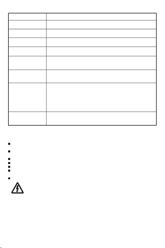
5.3 Wiring Specifications
Wiring and installation methods must comply with national and local electrical specifications.
The wiring specifications of the solar, battery must be selected according to rated currents, and see the
following table for wiring specifications:
Rat ed char ging c urren t
20A 5 /10 5/1 0
!
The wire size is only for reference. If there is a long distance between the PV array and the
controller or between the controller and the battery, larger wires can be used to reduce the voltage
drop and improve performance.
5.4 Connection
We strongly recommend connecting a fuse directly to the battery to protect any short circuit at the
battery wiring. Solar PV modules create current whenever light strikes them. The current created varies
with the light intensity, but even in the case of low levels of light, full voltage is given by the modules. So,
protect the solar modules from incident light during installation. Never touch uninsulated cable ends, use
only insulated tools, and make sure that the wire diameter is in accordance with the expected currents of
solar charge controller. Connections must always be made in the sequence described below.
WARNING: Risk of electric shock! Exercise caution when handing solar wiring. The solar
PV array can produce open-circuit voltages in excess of 100V when in sunlight. Pay more
attention to it.
WARNING: Risk of explosion! Once the battery's positive and negative terminals or leads
that connect to the two terminals get short-circuited, a fire or explosion will occur. Always
be careful in operation.
1st step: Connect the battery
Connect the battery connection cable with the correct polarity to the middle pair of terminals on the
solar charge controller (with the battery symbol). If the system is 12V, please make sure that the battery
voltage is within 5V~15.5V, else if the system is 24V, the battery voltage should between 20V~31V.
2nd step: Connect the solar module
Ensure that the solar module is protected from incident light. Ensure that the solar module does not
exceed the maximum permissible input current. Connect the solar module connection cable to the correct
polarity of the left pair of terminals on the solar charge controller (with the solar module symbol).
3th step: Final work
Tighten all cables connected to the controller and remove all the debris around the controller (leaving a
space of approx. 15 cm).
5.5 Grounding
Be aware that the negative terminals of controller are connected together and therefore have the same
electrical potential. If any grounding is required, always do this on the negative wires.
For common-negative system, such as motorhome, it is recommended to use a commonnegative controller; but if in the common-negative system, some common-positive
equipment are used, and the positive electrode is grounded, the controller may be
damaged.
Sol ar wire d iame ter(m m²/AW G)
③
④
②
①
Bat tery w ire di amet er(mm ²/AWG)
8
Page 10

6.Bluetooth
a
mu
tion
C
1 Blu
6. etooth om
o o
Bluet oth c m
1 rt dro
Suppo An i
.
i e w
ea
2 R
. l z
e gh performa
3.
. uet t .
4 Adopt Bl
communi a i n di
5
Refer to Bluetooth APP instructions for detailed operation of mobile APP.
6 B tter
n
he o troller a
t
a
y
el b t er
.2.1 L id, E
When choo ng L qui
ing
charg
vo t ge p
Cha rging s tage
Cha rging v olta ge rang e
Def ault ch argin g volt age
ge
volta
Low
di ) 8 6 .
v t ge
a
Low ol
ge rec
t
vo
l a o
Low
6.2. ithium2 L
meters settinra
Pa
①
When c
ho si
di nd l w
sconnect a
s f l
nge
is aol
r
a
t l a T
arget vo
harge
Charge recov
ge
t
v
a
ol
ow
L
vo t ge
Low l a
ar
0
Ch
℃
②
Chargi
"0
nt
c
roller det ts tha the ambient t
o
the
he
ambi
hen t
,
s norma
f
se i the
The user c n sel t the
nic
n ha f
i
muni
o
cat
d mo
bile pho e P
rel t ng f i o r l
ess moni ori
i
nc t
e, ul ra-
2 nd BL t hno o
a E
h 4
oo
s 1
o
c t
tance up to
pe.2 a y
y T
ppl e
s to he facto def
i
.G
G
olta
a
r meters a 5
disconnect nd lo
o
di )
re o ne
a . -
gin
ng
lse if he ha
℃
"
0
a ec
The low voltage reconnect(LVR) should be higher than the low voltage disconnect (LVD) at
least 0.6/1.2V, if you want to improve LVD, you should first improve LVR.
Note: (Charge recovery voltage+1.5V)≥Lithium ≥(
voltage
Mobile App does not support parameters beyond this range.
Warning: The required accuracy of BMS shall be at least 0.2V. If the deviation is higher than
0.2V, the manufacturer will assume no liability for any system malfunction caused by this.
Li d, el AGM and G
G
L,
A M6 iqu
i d,
G L or A
ca e set mobile p ne A P
re 2 ℃
a
VD setting
sconnect(L
VR
L
nnec
t(
g
um b t
t
ng l
i hi at
a
l
ge rec
t
vo
o
o
w.
t ge(CV ) s
l a V
t ge(C R) set i ng :
y vo
sconnect(LVD
c (L t ng 6 V
t VR) set i r
g
"
i n i
unc
f t o s only a i
ec t e
ent empera
t
,
℃ C rgi
0
ng"
i
Chargi
a
+0.2V)
o g ha a
l
l win
s the o
P
n A
.
unct on of solar c nt o ler.
o
w
l
o
qui
E
by
2
/1
w
t
) set
ery
o
et
s
e t ng - 0
ture is lo
s t
s
to
e
ppropri
ns
power c
ec l gy.
m.
0.
,
te
a
r
f
G
b t
M o
ho
em p
V syst aramet 24V syst
Boo st
14. 0~14. 8V
14. 5V
l a c n a
vo t ge reconnect
: 10. 11
a
- .
nge
r
1 .
a
1
ing r nge:
he ha a
t ,
t c rge t rget l
ype
l t
nnect of
nge:
r
iC t ng
a 10.0
e
ng ra
t
i .6
t
range: 9.0
nge: 9
b f
ppl c
le o
a
pe
m
ha , i
w
n 0 f t
t
" s set o
i t sl
ng
" " t
he cont l
No ,
a
te charging m
i :
i
t
cs
st
er
c
c r
uet t
umpt
y type, t
r
P
~1
4
um ba t
-
3
9 2
.
3
r
lithium b t r
a ur i
r
o "
"
oo h dedic ted chipUs hi
ion Bl
, t
a te
u
Lithi m b t ry
he p er bo
. ra e s a o
The range o
ers,
a lso s t b
8V/21
2
.8V/2 . ~ 5
vo
y
er
0 a t 1 .
2
. V (def
(def
3 .
- 1 8V
0 a t 10
V (def
.
3
V ( f
.
0 de
1
s hi
e
t
"
he ℃
0 C
he
t m x charging c rrent
w
l t he t y.
ro
er does no charge t ba
e d.
tho
s o
aramet
m ters i s f l
f pa
em a m
uto a
Equ aliza tion
14. 0~15. 0V
14. 8V
be e y o
Bluet
de
V
23
-
6
. . ( f
V /
2 .
2 8
6 a t 1
, w
t
charge r
age
a i
c n be set by mob l one APPi hi t
)
4 4V
ul :
V)
1 .
ul
0er
a t: 4
V)
ul :
ul : 12 0 c n
)
.
t
a
n be set o
c
, i
te
a
t a
y
gher t ℃,
han 0
i
ha
"
rging s set
a
Charge target voltage Charge recovery
a .
t
a
y
r
set i
ul
, nd f o t
f ost
a t pl e
t
lly mul i
ic
oth app o
2 . )
a 1
1 2/ 2 4
ult: V
: 2.0 24.0
ul
ery l
vo
ecov
e ph
"
"
Yes S o or No
t
he ha gi
t c r ng func i n i
, t
Yes"
t "℃
o he chargi unct
0 r t
u
% o
is 2
terel
t bl
ng i
t
s sui a
t
liza ionequa
a l
l s. l w
ow The fol
.
i d by 2l a a
Flo at
13. 0~14. 5V
13. 7V
e pho
i
l ne.
f mob
V
) (def
vo
e, lo
a
g
t
, he
setti
t
,
" ".℃
"
" l w
s n rma .
o
t
ng f i
ed c re
a
f the
o
l
t
o
e for T c
a si
ing v ge n b
a
ge
ng
When
ur
l
on w
n
t,i l e t "
9
Page 11

7, LED indications, Pr otections and Mainte nance
7.1 LED Display
LED
Sol ar LED
(Re d)
Bat tery L ED
(Bl ue)
Bat tery C apac ity
LED
(Re d, Ora nge,
Gre en, Gre en)
7.2 Fault s & Alarm s
Fau lt
Hig h volt age at
bat tery t ermin al
Can 't rec ogniz e
blu etoo th
Can 't rec ogniz e
sys tem vo ltage
Ba tte ry c an' t
be c har ged
du rin g day tim e
Sol ar LED
Soc 2
Soc 1
Sta tus
On
Fas t Flas h(0. 1s/0. 1s)
Fla sh(0. 5s/0. 5s)
Slo w Flash (0.5s /2s)
Off
On
Fla sh(0. 2s/0. 2s)
Soc 1 Flash (0.2s /0.2s , Red)
Soc 4 Flash (0.2s /0.2s , Green )
Soc 1 On
Soc 2 On
Soc 3 On
Soc 4 On
Rea son
Bat tery v olta ge is too h igh
Com munic ation f ailur e
Bat tery v olta ge is abn ormal
at st art-u p
PV panel fault or reverse
connection
Bat tery L ED
Soc 3
Bat tery C apac ity LE D
Soc 4
Fun ction
Sol ar pane l is cor rectl y conne cted,
but n ot char ged
MPP T charg ing
Equ al or Boo st char ging
Flo at char ging
Nig ht
Bat tery i s norm al
Over temper ature
Low v oltag e prote ctio n
Ove r volta ge prot ecti on
Bat tery c apac ity < 20 %
20% < B atter y capa city < 5 0%
50% < B atter y capa city < 9 0%
Bat tery c apac ity > 90 %
Troub lesho oting
Check if other sources overcharge the battery.
If not, controller is damaged.
Rec onne ct aft er di scon nect ing t he bat tery
for a bout 1 m inut e and re conn ect t he
Blu etoo th de vice .
Cha rge or d ischa rge th e batt ery s o that t he
bat tery v olta ge is w ithi n the no rmal
ope rati ng ran ge (5~ 15.5 V or 20 ~31V ).
Che ck pane ls and c onnec tion wi res.
10
Page 12
7.3 Protect ion
Pro tecti on
PV Ov er Curr ent
PV Sh ort Ci rcui t
PV Re vers e Polari ty
Bat tery Re verse Po lari ty
Bat tery O ver vo ltag e
Bat tery O ver di schar ge
Ove r Temp erat ure
Pro tecti on
Dam aged Re mote
Tempe ratur e Senso r
7.4 Maintenanc e
The f ollow ing ins pecti ons and m ainte nance t asks ar e reco mmen ded at le ast two t imes pe r year
for b est per form ance .
Mak e sure n o bloc k on air-f low aro und th e contr olle r. Cle ar up any d irt an d frag ments o n
rad iator.
Che ck all th e naked w ires t o make s ure in sula tion is n ot dama ged. Re pair o r repl ace so me wire s
if ne cessa ry.
Tig hten al l the ter mina ls. Ins pect fo r loose , broke n, or bu rnt wi re conn ecti ons.
Pay a tten tion t o any tro uble shoot ing or er ror ind icat ion .Take c orre ctiv e actio n if nece ssar y.
Con firm th at all th e syste m compo nent s are gro und co nnect ed tigh tly an d corre ctly.
Con firm th at all th e termi nals h ave no co rrosi on, in sulat ion dam aged, h igh tem perat ure or
bur nt/di scolo red sig n, tig hten te rmin al scre ws to the s ugge sted to rque .
Che ck for di rt, ne stin g insec ts and co rrosi on. If s o, clea r up in tim e.
WARNING:Risk of electric shock!
Make sure that all the power is turned off before above operations,
and then follow the corresponding inspections and operations.
Des cript ion
The c ontro ller w ill lim it char ging po wer in ra ted ch arge po wer.
An ov er-siz ed PV ar ray wil l not ope rate at m aximu m power p oint .
Whe n PV shor t circu it occu rs, th e cont roll er will s top ch argin g.
Rem ove it t o star t norm al ope rati on.
Ful ly prot ecti on agai nst PV re vers e polar ity, no da mage to t he
con troll er. Cor rect t he con necti on to sta rt nor mal op erat ion.
Ful ly prot ecti on agai nst bat ter y reve rse po larit y, no dama ge to the
con troll er. Cor rect t he con necti on to sta rt nor mal op erat ion.
If th ere are o ther e nergy s ourc es to ch arge th e batt ery, w hen th e
bat ter y volt age exc eeds 15 .8 / 31. 3V, the con troll er will s top cha rging
to pr otec t the bat ter y from o verc harg ing da mage.
Whe n batte ry vo ltag e drops t o the se tting v olta ge poin t of low vo ltag e
dis conne ct ,the l ow volt age pro tect ion in dicat or of the c ontr olle r will
fla sh.
The c ontro ller d etect s the int ernal t empe ratur e thro ugh int erna l senso r,
whe n the tem perat ure exc eeds t he sett ing val ue, th e charg ing cu rrent
wil l lower d own fol lowed b y the dec reas e of temp erat ure, s o as to
con trol th e cont rolle r's tem pera ture ri se, wh en the in terna l
tem perat ure exc eeds t he sett ing ove r temp eratu re prote ction
thr esho ld, the c ontro ller st ops wo rking a nd rest ores a fter t he
tem perat ure is lo were d.
If th e tempe ratur e sens or is sho rt-ci rcui ted or d amag ed, the c ontro ller
wil l use the i ntern al temp erat ure for c harg ing tem pera ture
com pensa tion.
11
Page 13

8, Tec hnical Data
Ite m
Sys tem vol tage
Max c harg ing cu rrent
MPP T char ging v oltag e
Boo st vol tage
Equ aliz atio n volt age
Flo at volt age
Low v olta ge dis conn ect
Bat tery
Low v olta ge rec onnec t
Par ameter s
Temp . comp ensa tion
Cha rging t arge t volt .
Cha rging r ecov ery v olt.
Low v olta ge dis conn ect
Low v olta ge rec onnec t
Max v olt on b at. te rmina l
Bat tery t ype
Max v olt on P V(-2 0℃)
Pan el
Max v olt on P V(25℃)
Par ameter s
Max i nput p ower
MPP T trac king r ange
Max t rack ing ef fici ency
Max c onve rsio n effi cien cy
Dim ensi ons
Wei ght
Sys tem
Com muni cati on
Par ame-
Gro undin g
ter s
Pow er ter minal s
Amb ient t empe ratu re
Sto rage t empe ratu re
Amb ient h umid ity
Pro tecti on deg ree
Max A ltit ude
*1. This va lue re prese nts the m aximu m volta ge of th e sola r panel a t the min imum op erati ng
amb ient te mpera ture.
*2. Voc mean s the ope n circu it vol tage of t he sol ar pane l.
*3. Aroun d obliq ue line v alue s epara tely o n behal f of 12V an d 24V sy stem's v alue.
Win 500-M PPT
12/ 24V aut omati cal rec ogni zatio n
20A
bef ore boo st or eq ualiz ation c hargi ng stag e
14. 0~14. 8V/28 .0~29 .6V(d efaul t:14. 5/29. 0V@25℃ )
14. 0~15. 0V/28 .0~30 .0V(d efaul t:14. 8/29. 6V@25℃ )
13. 0~14. 5V/26 .0~29 .0V(d efaul t:13. 7/27. 4V@25℃ )
10. 8~11. 8V/21 .6~23 .6V(d efaul t: 11.2 /22.4 V)
11. 4~12. 8V/22 .8~25 .6V(d efaul t: 12.0 /24.0 V)
-4. 17mV/ K per cel l (Boos t, Equa lizat ion),
-3. 33mV/ K per cel l (Floa t)
10. 0~32. 0V(Li thium , defau lt: 14. 4V)
9.2 ~31.8 V(Lit hium, d efaul t: 14.0 V)
9.0 ~30.0 V(Lit hium, d efaul t: 10.6 V)
9.6 ~31.0 V(Lit hium, d efaul t: 12.0 V)
35V
Gel , AGM, Li quid , Lithi um(de fault : Gel)
*1
55V
50V
260 /520W
(Bat tery Vo ltag e + 1.0V)~Vo c*0. 9
>99 .9%
98. 0%
164 * 1 07 * 32mm
700 g
BLE
Com mon Neg ative
AWG (5mm ²)
10
-20 ~ + 55℃
-25 ~ + 80℃
0 ~ 100 %RH
IP5 4
400 0m
*2
12
 Loading...