

Page 1
VS-LC101
CaptureVision Station
Quick Installation Manual
-English
[Important]
To download the latest version of Quick Start
Guide, multilingual user manual, software, or
driver, etc., please visit Lumens
http://www.Mylumens.com/support.php
Page 2

z
z
z
z
z
z
z
z
z
z
z
1 Preparation before use
Very Important
z Please activate your warranty: http://www.MyLumens.com/reg
z To download the updated software, multilingual manuals, and Quick Start Guide, please
visit Lumens™ web site at: http://www.mylumens.com/support.php
z To ensure successful installation, please be sure to follow each of the following steps
1.1 Equipment requirements
VS-LC101 x 1
Webcam x 1 ~ 3, e.g. VC-A20P3 x 3
Computer (or Laptop) x 1
Router x 1, Giga router recommended
Display x 1
Network cables x 3 ~ 5
HDMI or VGA cable x 2
External hard drive: USB or eSATA external hard drive x 1
Amplifier x 1
Audio mixer x 1
Speaker set x 1
1
Page 3
z
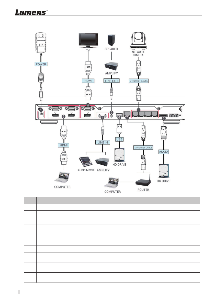
2 How to connect
Please follow the following instruction to complete the connection.
NO. Function How to connect
Power Connect the power cord
1.
Image input Connect the computer HDMI to the HDMI IN 1
2
2.
Image output Connect HDMI OUT to the TV HDMI
3.
Audio input Connect Line devices for audio input, e.g. amplifier, audio mixer
4.
Audio output Connect Line devices for audio output, e.g. amplifier
5.
Storage
6.
Device
LAN Connect the WAN port to the router to link with the computer in
7.
Internet image
8.
input
Note: Replace the image input device from the computer to other devices
as needed, e.g. projector.
Note: If the TV does not provide HDMI, use an adapter instead according
to the TV specification
Insert USB or eSATA external hard drive as the storage device
order to conduct remote management of VS-LC101
Connect webcam (e.g. VC-A20P) for image input
Page 4
z
z
z
z
z
z
z
z
z
z
z
3 Instruction for installation and setting
3.1 Confirm and set the VC-A20P network configuration
Use a C-Video cable or a DVI cable to connect VC-A20P and the monitor (refer to the
figure below for the connection method)
After the power is switched on, press the [MENU] button on the VC-A20P remote to
open the OSD menu.
Move down to [Ethernet]; press [
Press [ ] to enter the [DHCP] setting; confirm [DHCP] to be in [Close] state.
Press [MENU] to exit the [DHCP] setting
Confirm the [IP Address] is the preset [192.168.100.150]
[Remark] If there are more than one VC-A20P to be connected, please modify the IP
address to [192.168.100.x]Ǵe.g. [192.168.100.151], [192.168.100.152]…etc.
After complete the confirmation of the address and modification, repeat pressing the
[MENU]
button to exit OSD menu.
] to enter
DVI cable
Monitor or HDTV
/
C-Video Cable
TV
[Remark] For VC-A20P relevant use and operation method, please visit Lumens website;
download and read the VC-A20P operation manual.
Ô Before begin the following settings, please confirm that the connection has been
completed according to
2 instruction of connection.
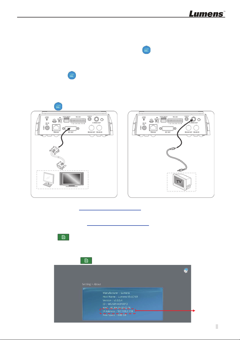
3.2 Confirm the VS-LC101 IP Address
Press the button on the VS-LC101 remote control; open OSD menu
Move rightward to [Setting]; press [OK]; and enter the setting page.
Move downward to [About]; press [OK]; and enter the setting page to confirm the IP
address.
Repeat pressing the button to exit OSD menu
VS-LC101
IP Address
3
Page 5

z
z
z
z
z
3.3 Connect to the VS-LC101 Webpage (including log in)
[Remark 1] For the computer that remotely controls VS-LC101, the network interface
card needs to be set to obtain the IP address automatically.
Open the web browser on the computer
Enter the VS-LC101 IP address, e.g.: http://192.168.2.118
[Remark 2] Chrome or Safari browser recommended
Select [Admin]
Input the VS-LC101 Admin account and password.
User: admin
Password: admin
Click [Log in] to log in
4
Page 6

z
z
z
z
z
z
z
z
3.4 Settings
3.4.1 Confirm the time setting.
Confirm the time to be correct. If time modification is required, use the manual
setting or select other NTP servers.
3.4.2 Format a hard drive
Open the [Local Storage Setting] page,
d
c
e
f
Select a hard drive. For the initial use, please format the hard drive first. It
takes few minutes to format the hard drive and the duration varies according to
different storage device formats. Before the formatting is completed, please do not
close the webpage. Until the “Formatting…” message is closed, the formatting is
completed.
Check [Enable Local Storage] to load the hard drive.
If recycling the use of hard drive storage space is required, check [Cycling
Record]. Then, when the hard drive space is completely used, the old data will be
overwritten by the new data in order to continue storing.
Select [USB1] drive, make the selection according to the storage device.
Press [Apply] to apply the setting.
The state of the storage device will change to [Mounted] and the storage device
setting is completed.
5
Page 7

z
z
z
z
z
z
3.4.3 Connect webcam
d
c
e
f
Open the [Source Setting] page
Execute the [Refresh] function of [Discovery].
After the search is completed, the list will show the webcam that can be connected.
Click the webcam.
Input the VC-A20P account password
Administrator: admin
Password: 9999
g
Press [Submit] and wait until the state of the webcam is [OK]
3.4.4 Setup the image input
Click [Video Source] page. Set the video sources of CH1ǵCH2ǵCH3ǵCH4
6
c
g
Page 8

z
z
z
z
z
z
z
z
z
z
CH1: Click [Channel1]; select [Computer] from the channel name; set image as
[Video Port]; Select image port [HDMI1 or VGA1]
d
e
Î
CH2: Network Camera Æ Select Camera
Select other already connected video inputs for CH3, CH4 respectively.
Press [X] at the upper right and close the setting window.
Press [Apply] to apply the setting.
f
3.4.5 Audio In
Audio Volume
Press [Apply] to apply the setting.
[Remark] When Line In is connected to a microphone, please click to change
to microphone input.
3.4.6 Screen and video programming
Open the [Layout Manager] page
Set [Display layout] style. There are totally 9 sets of style available for setting.
Set [Record layout] style. There are totally 9 sets of style available for setting.
After the above setting is completed, please log out from the webpage.
7
Page 9

z
z
z
z
z
z
z
z
z
z
3.5 Confirm the setting is normal.
3.5.1 Confirm the setting of the screen split style.
Confirm whether there are images on CH1 ~ 4. If the image is different from the
setting, please refer to
Use the remote control; press the button; confirm whether the 9 video split styles
3.4.3 Setup the image input
are the same as the plan. Blue color represents the current style applied.
Use the remote control; press the button; confirm whether the 9 screen split
styles are the same as the plan. Blue color represents the current style applied.
3.5.2 Confirm that the screen capture function is normal.
Use the remote control; test the screen capture function. If failed, please refer to
3.4.1 Format a hard drive
Use the remote control and press the button to capture screen images.
to confirm whether the hard drive is installed correctly.
3.5.3 Confirm that the recording function is normal
Use the remote control; test the recording function. If failed, please refer to
Format a hard drive
Use the remote control and press the Ʌ button to begin recording; press the Ɏ
to confirm whether the hard drive is installed correctly.
button to stop recording.
3.5.4 Confirm that the playback function is normal
Use the playback function to confirm the photograph and video results.
Use the remote control; press the button to open the OSD menu.
Select [Playback] -> [Local Storage]
[Photo] -> Select the folder by date -> choose photo
Press to exit the photo browser.
[Video] -> Select the folder by date -> Select the video and begin to play.
Press to exit the video play
[Remark] When use the playback function for the first time, a message [Storage
device mounting…] will appear, indicating LC101 supports the format of storage
device being mounted normally.
If the above function can be performed normally, then the installation is completed. Use of
the operational functions or detailed descriptions of various settings and functions of
VS-LC101, please refer to Lumens website; download and read the VS-LC101 User
Manual.
to reset the setting.
3.4.1
8
Page 10

4 Product Overview
4.1 Host Computer Front Panel Description
NO. Name Function Descriptions
1. Remote
sensor
2. Indicator Record / Power
3. Function
keyboard
shortcuts
4. Operation
selection key
5. Power button Power Switch
6. Output plug Plug in the USB-supporting hard drive to output files or update
4.2 Host computer backend I/O Description
IR Receiver
Record / Play / Pause / Stop / Menu / Channel / Split Display
Up / Down / Left / Right / Return / OK
firmware via the USB-supporting hard drive.
NO. Name Function Descriptions
7. Power jack 12V / 2A
8. Image input VGA / HDMI device image input
Note: Use DVI to HDMI adapter or component to VGA cable device
for image input.
9. Image output VGA / HDMI device image output
10. Audio input Line / MIC device audio input
11. Audio output Line audio output can be transmitted to the amplifier device.
12. Hard drive
plug
USB / eSATA supporting interface for the interface of storage
hard drive
13. LAN Connected to LAN
14. Webcam
Webcam image input
image
15. DIDO RS-232 bilateral control signal adaptor
16. Reset button Return to the default values
9
Page 11

5 Remote control brief description
NO. Icon Name Function Descriptions
1.
X
2.
3.
4.
5. Pause Pause playing. Pause recording.
6.
7.
Ʌ
8.
9.
Ɏ
10.
cdef
11.
12.
OK
13.
14.
10
Power Turn on / off.
Play Play the video. Press again while playing, the video
will pause.
Previous /
Next
Video
version type
Snapshot Capture the screen image and save to a file.
Previous / Next video while playing.
During recording, switch between recording image
configurations.
Record Start recording.
Menu Enter Main menu: Play / Record / Set.
Stop Stop playing. Exit recording.
Split Display In the lower part of the screen, switch between the
Up, down,
screen layout models.
Move Up / Down / Left / Right to select the item.
left, and right
OK The executed items in the menu. Display and zoom in
window in the lower part of the screen.
Return Return to the previous level menu or cancel the
Mute Turn off the audio.
selection.
 Loading...