

Page 1
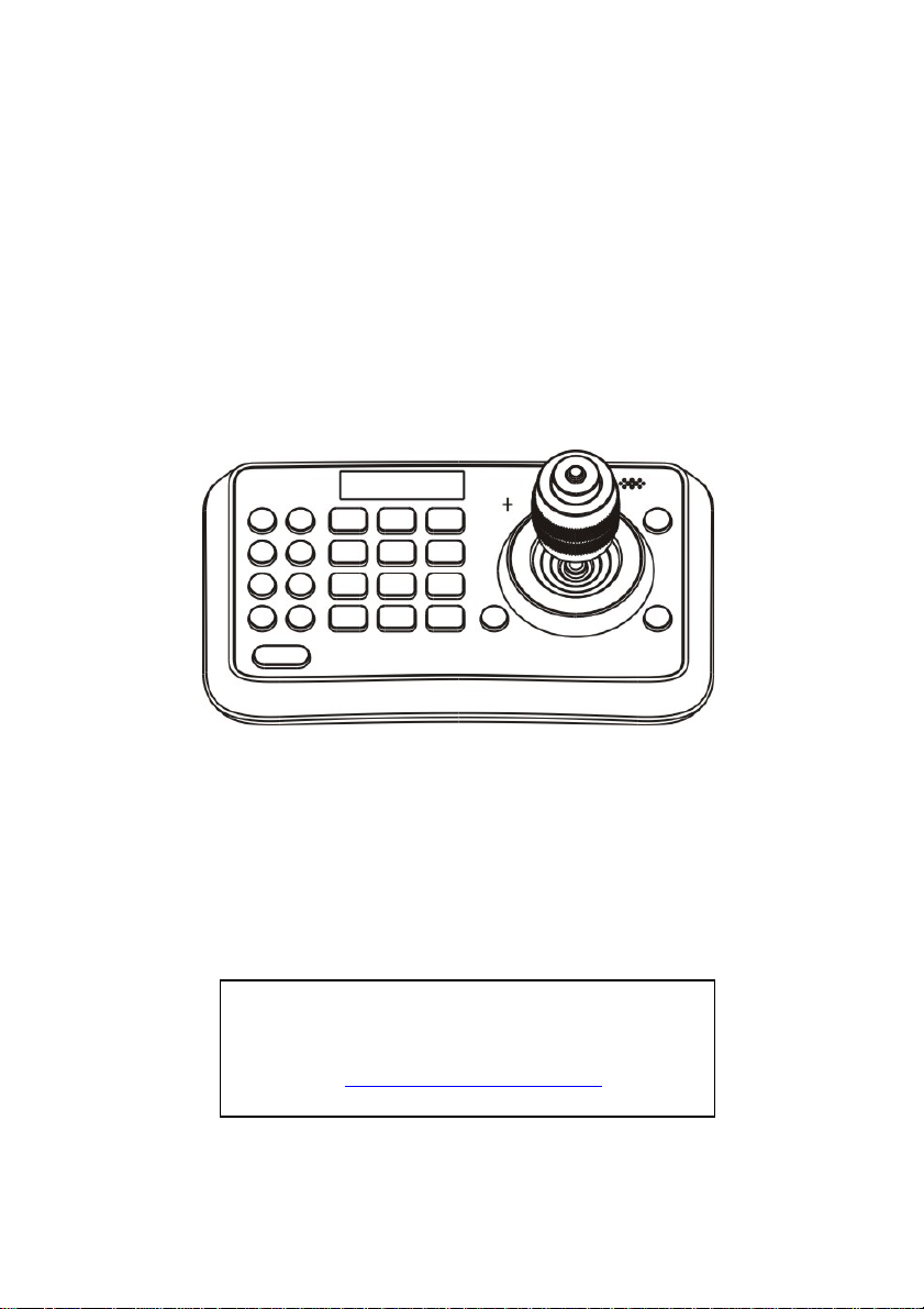
VS-K20
Compact Camera Controller
User Manual – English
[Important]
To download the latest version of Quick Start
Guide, multilingual user manual, software, or
driver, etc., please visit Lumens
http://www.Mylumens.com
Page 2

Table of Contents
Copyright Information ....................................................................................... 2
Chapter 1 Safety Instructions .......................................................................... 3
Precautions .................................................................................................. 4
FCC Warning ................................................................................................ 4
EN55022 (CE Radiation) Warning ............................................................... 4
Chapter 2 About The Product .......................................................................... 5
2.1 Introduction ......................................................................................... 5
2.2 Features ............................................................................................. 5
2.3 Technical Data .................................................................................... 5
2.4 Parts and view .................................................................................... 6
2.5 Connections ........................................................................................ 8
Chapter 3 Setting Menu .................................................................................. 10
Chapter 4 Menu operation .............................................................................. 12
4.1 Camera Setting................................................................................. 12
4.2 Time Setting ..................................................................................... 13
4.3 Volume Setting ................................................................................. 13
4.4 Backlight Setting ............................................................................... 13
4.5 Sleep Setting .................................................................................... 14
4.6 Pin Setting ........................................................................................ 14
4.7 Joystick Calib .................................................................................... 15
4.8 Speed Setting ................................................................................... 15
4.9 Default Setting .................................................................................. 16
English - 1
Page 3

Copyright Information
Copyrights © Lumens Digital Optics Inc. All rights reserved.
Lumens is a trademark that is currently being registered by Lumens Digital Optics
Inc.
Copying, reproducing or transmitting this file is not allowed if a license is not
provided by Lumens Digital Optics Inc. unless copying this file is for the purpose
of backup after purchasing this product.
In order to keep improving the product, Lumens Digital Optics Inc. hereby
reserves the right to make changes to product specifications without prior notice.
The information in this file is subject to change without prior notice.
To fully explain or describe how this product should be used, this manual may
refer to names of other products or companies without any intention of
infringement.
Disclaimer of warranties: Lumens Digital Optics Inc. is neither responsible for any
possible technological, editorial errors or omissions, nor responsible for any
incidental or related damages arising from providing this file, using, or operating
this product.
English - 2
Page 4

Chapter 1 Safety Instructions
Always follow these safety instructions when setting up and using the Camera
Controller:
1. Use attachments only as recommended.
2. Use the type of power source indicated on the Camera Controller. If you are
not sure of the type of power available, consult your distributor or local
electricity company for advice.
3. Always take the following precautions when handling the plug. Failure to do
so may result in sparks or fire.
Ensure the plug is free of dust before inserting it into a socket.
Ensure that the plug is inserted into the socket securely.
4. Do not overload wall sockets, extensions leads or multi-way plug boards as
this may cause fire or electric shock.
5. Do not place the Camera Controller where the cord can be stepped on as
this may result in fraying or damage to the lead or the plug.
6. Never allow liquid of any kind to spill into the Camera Controller.
7. Except as specifically instructed in this User Manual, do not attempt to
operate this product by yourself. Opening or removing covers may expose
you to dangerous voltages and other hazards. Refer all servicing to licensed
service personnel.
8. Unplug the Camera Controller during thunderstorms or if it is not going to be
used for an extended period. Do not place the Camera Controller or remote
control on top of vibrating equipment or heated objects such as a car, etc.
9. Unplug the Camera Controller from the wall outlet and refer servicing to
licensed service personnel when the following situations happen:
If the power cable or plug becomes damaged or frayed.
If the Camera Controller is wet with liquid, rain or water.
<Note> Using an incorrect battery type in the remote control may result in
breakdown. Follow local instructions on how to dispose of used batteries.
English - 3
Page 5
Precautions
Warning: To reduce the risk of fire or electric shock, do not expose this
appliance to rain or moisture.
If Camera Controller will not be used for an extended time, unplug it from the
power socket.
Note
Risk of Electric Shock
Caution: To reduce the risk of electric shock, do not remove cover (or back). No
user-serviceable parts inside. Refer servicing to licensed service personnel.
This symbol indicates that
this equipment may contain
dangerous voltage which
could cause electric shock.
DO NOT OPEN
This symbol indicates that
there are important operating
and maintenance
instructions in this User
Manual with this unit.
FCC Warning
This Camera Controller has been tested and found to comply with the limits for a
Class A digital device, pursuant to Article 15-J of FCC Rules. These limits are
designed to provide reasonable protection against harmful interference in a
commercial installation.
This digital apparatus does not exceed the Class A limits for radio noise emissions
from digital apparatus as set out in the interference-causing equipment standard
entitled "Digital Apparatus," ICES-003 of Industry Canada.
Cet appareil numerique respecte les limites de bruits radioelectriques applicables
aux appareils numeriques de Classe A prescrites dans la norme sur le material
brouilleur: "Appareils Numeriques," NMB-003 edictee par l'Industrie.
EN55022 (CE Radiation) Warning
This product is intended for use in a commercial, industrial, or educational
environment. It is not intended for residential use.
This is a Class A product. In a residential environment it may cause radio
interference, in which case the user may be required to take adequate measures.
The typical use is in a conference room, reception room or hall.
English - 4
Page 6
Chapter 2 About The Product
2.1 Introduction
The mini Compact Camera Controller is a full-function system keyboard.
With features of ergonomic design, multi-function, high reliability and easy
operation, it is a perfect controller for rugged PTZ cameras, video conference
cameras, surveillance cameras and so on
2.2 Features
4D joystick for pan/tilt/zoom/focus control, ergonomic design and
excellent finishing;
High brightness OLED display;
Auto backlight keys;
Multi-level protection from illegal operation or setting;
Multi-baud rate and protocols;
7address;
Batch program cameras in the systems;
Compact design with portable features;
2.3 T echnical Data
Comm. Interface
Protocol VISCA/PELCO-D
Baud Rate
Address 1~255
Joystick 4-axis (Left/Right, Up /Down, Zoom In/Zoom Out, Focus
Display OLED
Power DC12V
Power Consumption <2W
Working Temperature
Storage Temperature
Relative Humidity ≤90% (non-condensation)
Dimensions 200mm(L)*120mm(W)*103mm(H)
Net Weight 0.5kg
RS-232
9600bps、38400bps
Near / Focus Far)
0℃~+40℃
-20℃~+60℃
/RS422
English - 5
Page 7

2.4 Parts and view
1
0~9 (Numbers)
Those are keys used to input
numbers.
2
CALL (Call preset)
Input preset number, then press
CALL key to call a preset
3
CAMERA (Switch cameras)
Input camera number, then press
CAMERA key to switch to another
camera.
4
SET (Set / Clear preset)
Input preset number, then press
SET key to set or delete a preset
(Short press to “set”; long press to
“clear”).
5
SETUP (Enter setup menu)
Press SETUP key to enter menu
and program the keyboard
6
MIRROR (flip the image)
Press MIRROR key to control the
image flip of the camera.
(Normal/ Mirror/ Flip/ Mirror+Flip)
7
BACK LIGHT (Turn on/off Camera
back light compensation)
Press BACK LIGHT key to turn on /
off the back light compensation.
8
FREEZE (Freeze the screen)
Press FREEZE key to control the
image freeze of the camera.
9
LOCK (keyboard lock)
Press LOCK key to lock the control
keyboard and key in the user
password to unlock the keyboard.
10
POWER (Power switch)
Press POWER key to turn on / off
the camera.
11
ESC (Exit / Delete)
It is a key to EXIT in a menu or
DELETE in other operations.
12
ENT (Confirm)
It is used to confirm menu setting.
13
BRT-(turn down the brightness)
Press BRT- key to turn down the
image brightness.
English - 6
Page 8

Joystick
This joystick is used to Pan, Tilt,
Zoom and Focus
Non-Menu State:
Left/Right/Up/Down: Pan/Tilt the
camera correspondingly
Twist clockwise: Zoom In,
Twist anti-clockwise: Zoom Out;
Press Zoom/ Focus Switch Key
and Twist: Focus Near/Far
Menu State:
Right: Enter a submenu or
Confirm;
Left: Return to previous menu or
exit (expect some not returnable
menus);
Up: Move to last option;
Down: Move to next option.
1514
BRT+ (turn up the brightness)
Press BRT+ key to turn up the
image brightness.
16
Zoom / Focus Switch Key
This key is used to switch between
zoom and focus function.
Operation: Press this key, the
crisscross of indicator lighter near
the joystick will go out, twist the
joystick to zoom in / out; press this
key again, the crisscross of
indicator lighter will be lightened,
twist the joystick will adjust focus
value.
17
MENU (Enter Camera Menu)
This key is used to enter camera
menu.
English - 7
Page 9

2.5 Connections
2.5.1 Connections
RS-422
RS232 IN
Power DC12V
Camera
Camera
Display
Display
Power Supply
Compact Camera
Controller
English - 8
Page 10

2.5.2 RS-422 Pins instructions
Pin No. function
1 GND
2 RXD IN-
3 RXD IN+
4 TXD IN-
5 TXD IN+
2.5.3 RS232 Pins instructions
Pin No. function
1 NA
2 NA
3 TXD
4 GND
5 RXD
6 NA
7 NA
8 NA
English - 9
Page 11

Chapter 3 Setting Menu
<Remark> Press [SETUP] on the remote control to enter the setting menu; the
bold underlined values in the following table are defaults.
1st Level
Major
Items
2nd Level
Minor Items
Camera ID
3rd Level
Adjustment
Values
1~ C ~255
Function
Descriptions
Set camera ID
VISCA only works with
ID 1~7
Camera
Setting
Time
Setting
Time
Display
Volume
Setting
Backlight
Setting
Sleep
Setting
Pin
Setting
V
Protocol
PD
Baud Rate
Address
Set Time xx:xx:xx
-
-
-
-
1. 9600
2. 38400
1~ C ~7
1. On
2. Off
1. Off
2. 1~6
3. Auto
4. On
5. Off
1. Off
2. 60m
3. 30m
4. 10m
5. 5m
6. 1m
7. 30s
1. User
2. Admin
V:VISCA,ID 1~7
PD : PELCO D , ID
8~255
Set baud rate. This
baud rate must be the
same as the camera’s
baud rate.
Camera’s address,
this address must be
the same as the
camera’s ID.
Set time in 24 hour
format
Set the time display
Adjust the volume of
the controller
Set the backlight of
the controller on or off
Set sleep time of the
controller.
Set user and admin
pins of the controller
English - 10
Page 12

Joystick
Calib
Speed
Setting
Default
Setting
Information
Pan Left
Pan Right
Tilt Up
Tilt Down
Zoom Tele
Zoom Wide
Free State
-
-
-
-
- -
Save
Cancel
1. High
2. Middle
3. Low
1. Yes
2. No
-
-
Calibrate the joystick
leftward
Calibrate the joystick
rightward
-
Calibrate the joystick
upward
-
Calibrate the joystick
downward
-
Calibrate the joystick
with Zoom Tele
-
Calibrate the joystick
with Zoom Wide
-
setting menu, no need
any operation.
Save the calibration
setting
Cancel the calibration
setting
Set control speed of
the joystick.
Restore the keyboard
setting to factory
default.
Related information
for the control
keyboard
English - 11
Page 13

Chapter 4 Menu operation
After powered on, “USER PIN” will show on the controller’s screen. The initial
pin is “111111 ” .
Pin Error:When “USER PIN:ERROR” shows on screen, it indicates
wrong pin was input. Enter correct pin to get to next step
Pin Correct:Screen shows “
number. If there is no further operation for long time, screen will
display current time automatically. If still no operations, the controller
will enter sleeping mode.
Enter OSD menu
Press SETUP key.
Screen shows “ADMIN PIN:”. Initial admin pin is “111111“.
1” camera icon and default camera
4.1 Camera Setting
Set camera ID (Range from 1~255), corresponding protocol, baud rates
and camera address of the target cameras. Then every camera can be
controlled easily by choosing their relative camera ID.
1. Move up / down the joystick, choose “CAMERA SETTING”.
2. Right move the joystick or press ENT key to enter menu “ :".
Press number keys to input camera number (range from 1~255) . If
the input number exceeds this range, the system will show
“ERROR”. After the setting is finished, press ENT key to confirm。
3. “Protocol” Setting Menu. Move up/down the joystick, choose
Protocol ( V / PD)。
< Note > VISCA only works with Camera ID 1~7.
4. Baud rate setting. Move up/down the joystick, choose baud rate,
and right move the joystick or press ENT to confirm.
5. Address Setting. Input number to set camera address (range from
English - 12
Page 14

1~7). Press ENT to confirm.
6. After the camera setting is finished, the system will automatically
return to the main menu.
4.2 Time Setting
Set time in 24 hour format.
1. Move the joystick up/ down, choose ”TIME SETTING”.
2. Right move the joystick or press ENT to get into time setting menu,
“H” hour becomes editable, input digits from keypad or move
joystick up / down to set the “H” (range: 0~23).
If input digits by keypad, after the hour has been set, it will
automatically get into “M” minute setting;
if set by joystick, right move the joystick to get into “M” minute
setting. Move right / left the joystick to select from “H”, “M” and “S”
settings.
3. “M” minute setting menu. Set the “M” minute and “S” second, refer
to “H” hour setting.
4. Press ENT to save and return to Main Menu.
4.3 Volume Setting
6 levels of volume from low to high are available to choose from.
1. Move the joystick up/down, select “ VOLUME SETTING”.
2. Right move the joystick or press ENT to get into “ VOLUME
SETTING” ; after setting right move the joystick or press ENT to
confirm.
4.4 Backlight Setting
Back light mode enables the keys to be clearly presented even at very
dark environment.
1. Move the joystick up/ down, select “ BACKLIGHT MODE”.
English - 13
Page 15

2. Right move the joystick or press ENT to enter “BACKLIGHT MODE”.
Move the joystick up/ down to select backlight options. Right move
the joystick or press ENT to confirm.
4.5 Sleep Setting
Set sleep time of the controller. In non-menu status, the screen will
enter the sleep mode if no operation is performed for a programmable
period.
1. Move the joystick up/ down, select “ SLEEP SETING”.
2. Right move the joystick or press ENT to enter “ SLEEP SETTING” .
Move the joystick up/ down to select sleep time. Right move the
joystick or press ENT to confirm.
4.6 Pin Setting
Set user and admin pins of the controller.
1. Move the joystick up/ down, select “PIN SETTING”.
2. Right move the joystick or press ENT to enter “PIN SETTING”.
Move the joystick up/ down to select the PIN digits. Right move the
joystick or press ENT to confirm.
3. Enter the PIN setting menu. “OLD PIN” requires to be input, press
ESC to cancel input digit. If correct Pin is input, it will get into “NEW
PIN” menu. If wrong pin is input, “ERROR” will be displayed.
4. Input “NEW PIN”
5. “CONFIRM”: after new pin is input, input it again to confirm. If the
two pins don’t match, it displays “PIN NOT MATCH”, menu goes
back to “NEW PIN”.
6. If the two pins match, it displays “OK!” and new pin will be
applicable..
To disable “PIN PROTECTION” function, there is no need to input any
digit in both “NEW PIN” and “CONFIRM”, press
English - 14
ENT directly to confirm.
Page 16

To enable “PIN PROTECTION” again, simply set new pins with digits
During these operations, press key
ESC to exit the PIN setting menu.
4.7 Joystick Calib
After long-time use, the joystick may require calibration.
1. Move the joystick up/ down, select “JOYSTICK CALIB”.
2. Right move the joystick or press
“JOYSTICK CALIB” menu. “PAN LEFT” will be displayed, move the
joystick to the left limit and hold, then press
LEFT” calibration. It will enter next menu.
3. Refer to the setting of “PAN LEFT” to calibrate “PAN RIGHT”, “TILT
UP” and “TILT DOWN”.
4. ““ZOOM TELE” calibrating menu, twist the joystick clockwise until
limit position, and press
ENT.
5. “ZOOM WIDE” calibrating menu, twist the joystick anticlockwise
until limit position, and press
6. “FREE STATE” setting menu, no need any operation, simply press
ENT to confirm.
ENT to confirm, enter the
ENT to finish “PAN
ENT .
7. Upon completion of the above settings, "<SAVE> CANCEL" will be
displayed to save or cancel. Move the joystick left/ right to choose,
and press
ENT to confirm.
4.8 Speed Setting
Set control speed of the joystick.
1. Turn the joystick up/down, choose"SPEED SETTING".
2. Right move the joystick or press
menu. Move the joystick up/ down to switch among speed levels,
and right move the joystick or press
English - 15
ENT to enter "SPEED SETTING"
ENT to confirm.
Page 17

4.9 Default Setting
Restore the keyboard setting to factory default.
1. Move the joystick up/ down, choose "DEFAULT SETTING".
2. Right the joystick or press
menu, move the joystick left/ right, select options"<YES> NO",
press
ENT to confirm.
ENT key, enter "DEFAULT SETTING"
English - 16
 Loading...