

Page 1
CL510
Document Camera
Installation Guide
Version: V06
Date: 2015/05/07
Page 2

Table of Contents
Copyright Information .......................................................................................................................................... 2
Chapter 1 Safety Instructions ............................................................................................................................. 3
Precautions ..................................................................................................................................................... 3
FCC Warning ................................................................................................................................................... 3
FDA Warning ................................................................................................................................................... 3
EN55022 (CE Radiation) Warning .................................................................................................................. 3
EN60825 (Laser) Warning .............................................................................................................................. 3
Caution ............................................................................................................................................................ 3
Chapter 2 Package Contents ............................................................................................................................... 4
Chapter 3 Product Description ........................................................................................................................... 5
3.1 Body size ............................................................................................................................................... 5
3.2 IO description ........................................................................................................................................ 7
Chapter 4 Installation and Connections............................................................................................................. 8
4.1 Preparation before installation ............................................................................................................... 8
4.2 Switch setting ...................................................................................................................................... 10
4.3 System diagram ................................................................................................................................... 11
4.4 Set up the power frequency ................................................................................................................ 11
4.5 Set the position of the object to be captured (Laser mark) ................................................................. 11
4.6 AF Table Set for auto focus setting ..................................................................................................... 12
Chapter 5 Troubleshooting ................................................................................................................................ 14
Attachment 1 ....................................................................................................................................................... 15
English -
1
Page 3

Copyright Information
Copyrights © Lumens Digital Optics Inc. All rights reserved.
Lumens is a trademark that is currently being registered by Lumens Digital Optics Inc.
Copying, reproducing or transmitting this file is not allowed if a license is not provided by Lumens Digital Optics Inc.
unless copying this file is for the purpose of backup after purchasing this product.
In order to keep improving the product, Lumens Digital Optics Inc. hereby reserves the right to make changes to product
specifications without prior notice. The information in this file is subject to change without prior notice.
To fully explain or describe how this product should be used, this manual may refer to names of other products or
companies, nevertheless without any intention of infringement.
Disclaimer of warranties: Lumens Digital Optics Inc. is neither responsible for any possible technological, editorial errors
or omissions, nor responsible for any incidental or related damages arising from providing this file, using, or operating
this product.
English -
2
Page 4
Chapter 1 Safety Instructions
serviceable
Always follow these safety instructions when setting up and using the Ceiling Camera:
1. Use attachments only as recommended.
2. Use the type of power source indicated on the Ceiling Camera. If you are not sure of the type of power available,
consult your distributor or local electricity company for advice.
3. Always take the following precautions when handling the plug. Failure to do so may result in sparks or fire.
Ensure the plug is free of dust before inserting it into a socket.
Ensure that the plug is inserted into the socket securely.
4. Do not overload wall sockets, extensions leads or multi-way plug boards as this may cause fire or electric shock.
5. Do not place the Ceiling Camera where the cord can be stepped on as this may result in fraying or damage to the
lead or the plug.
6. Do not block the slots and openings in the Ceiling Camera case. They provide ventilation and prevent the Ceiling
Camera from overheating. Do not place the Ceiling Camera on the soft surface of sofas, carpets or others.
7. Never push any kind of objects through cabinet slots. Never allow any kind of liquid to spill into the Ceiling Camera.
8. Except as specifically instructed in this User Manual, do not attempt to operate this product by yourself. Opening or
removing covers may expose you to dangerous voltages and other hazards. Refer all servicing to licensed service
personnel.
9. Unplug the Ceiling Camera during thunderstorms or if it is not going to be used for an extended period. Do not
place the Ceiling Camera or remote control on top of heat-emitting equipment or heated objects such as a car, etc.
10. Unplug the Ceiling Camera from the wall outlet and refer serving to licensed service personnel when the following
situations happen:
If the power cable or plug becomes damaged or frayed.
If liquid is spilled into it or the Ceiling Camera has been exposed to rain or water.
11. Due to safety concerns, please make sure the ceiling mounting which you purchased complies with UL and VESA
standard. And it’s highly recommended to have the technical persons who are certified by local agents to apply
installation and replacement.
<Note> Using an incorrect battery type in the remote control may result in breakdown. Follow your country’s
instructions on how to dispose of used batteries.
Precautions
Warning: To reduce the risk of fire or electric shock, do not expose this appliance to rain or moisture.
If the Ceiling Camera will not be used for an extended time, unplug it from the power socket.
Note
Caution: To reduce the risk of electric shock, do not remove cover (or back). No userparts inside. Refer servicing to licensed service Personnel.
This symbol indicates that
this equipment may contain
dangerous voltage which
could cause electric shock.
Risk of Electric Shock
This symbol indicates that there
are important operating and
maintenance instructions in this
User Manual with this unit.
FCC Warning
This Ceiling Camera has been tested and found to comply with the limits for a Class A digital device, pursuant to Article
15-J of FCC Rules. These limits are designed to provide reasonable protection against harmful interference in a
residential installation.
FDA Warning
This Devise Complies with DHHS Radiation Rules, 21CFR Chapter 1, Subchapter J.
EN55022 (CE Radiation) Warning
This product is intended for use in a commercial, industrial, or educational environment. It is not intended for residential
use.
This is a Class A product. In a residential environment it may cause radio interference, in which case the user may be
required to take adequate measures. The typical use is in a conference room, meeting room or auditorium.
EN60825 (Laser) Warning
Laser Radiation Do Not Stare Into Beam Class 2 Laser Product
Caution
Danger of explosion if battery is incorrectly replaced. Replace only with same or equivalent type. Dispose batteries according to
manufacture’s instructions.
English -
3
Page 5
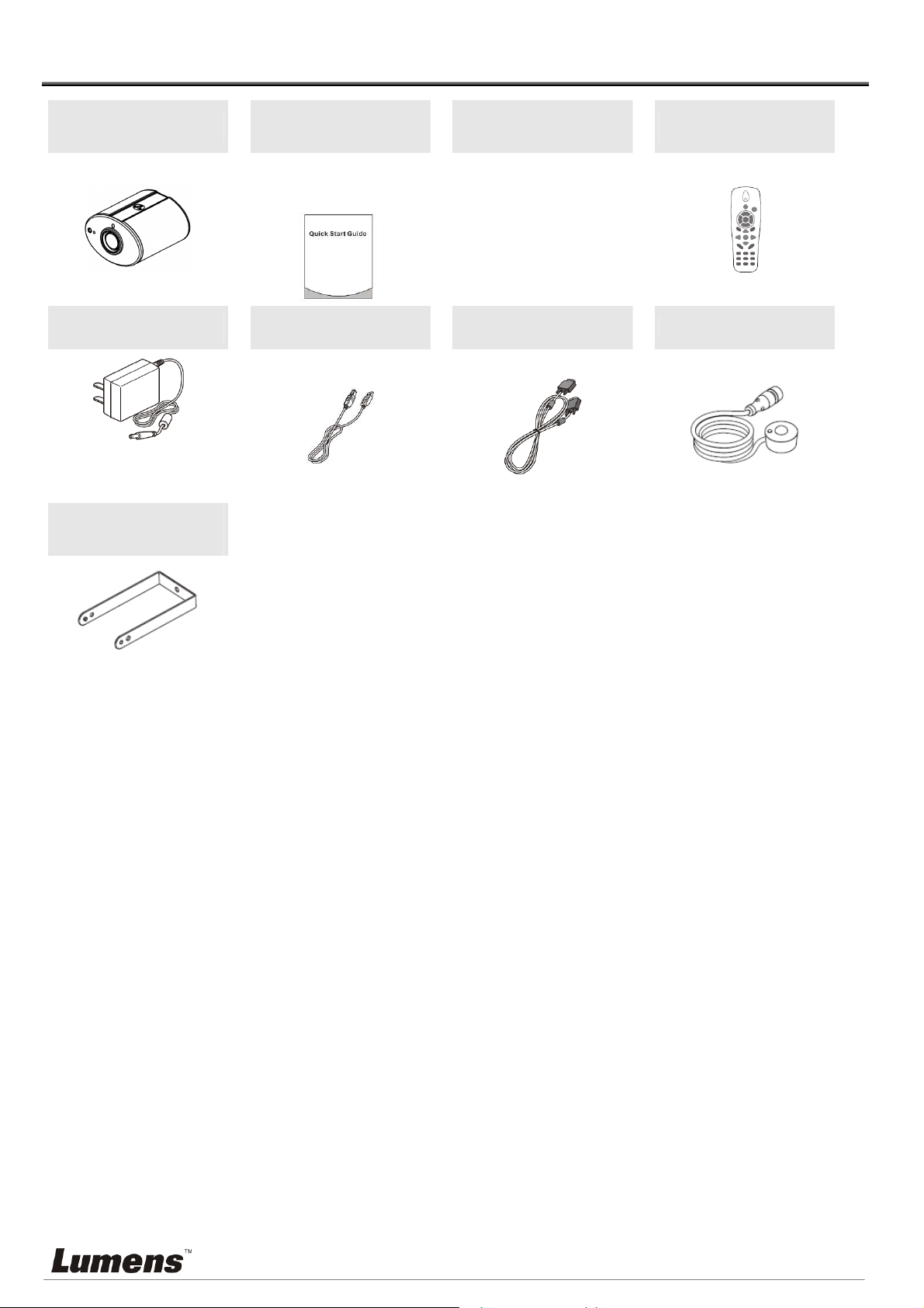
Chapter 2 Package Contents
CL510
Power Adapter
Appearance may vary
depending on
country/region
Ceiling Mount /
Hanger
Quick Start Guide
(For download of other
language versions, please
visit Lumens website)
USB Cable
Instruction for
Installation
VGA Cable
Remote Control
IR extender
English -
4
Page 6
Chapter 3 Product Description
3.1
Body size
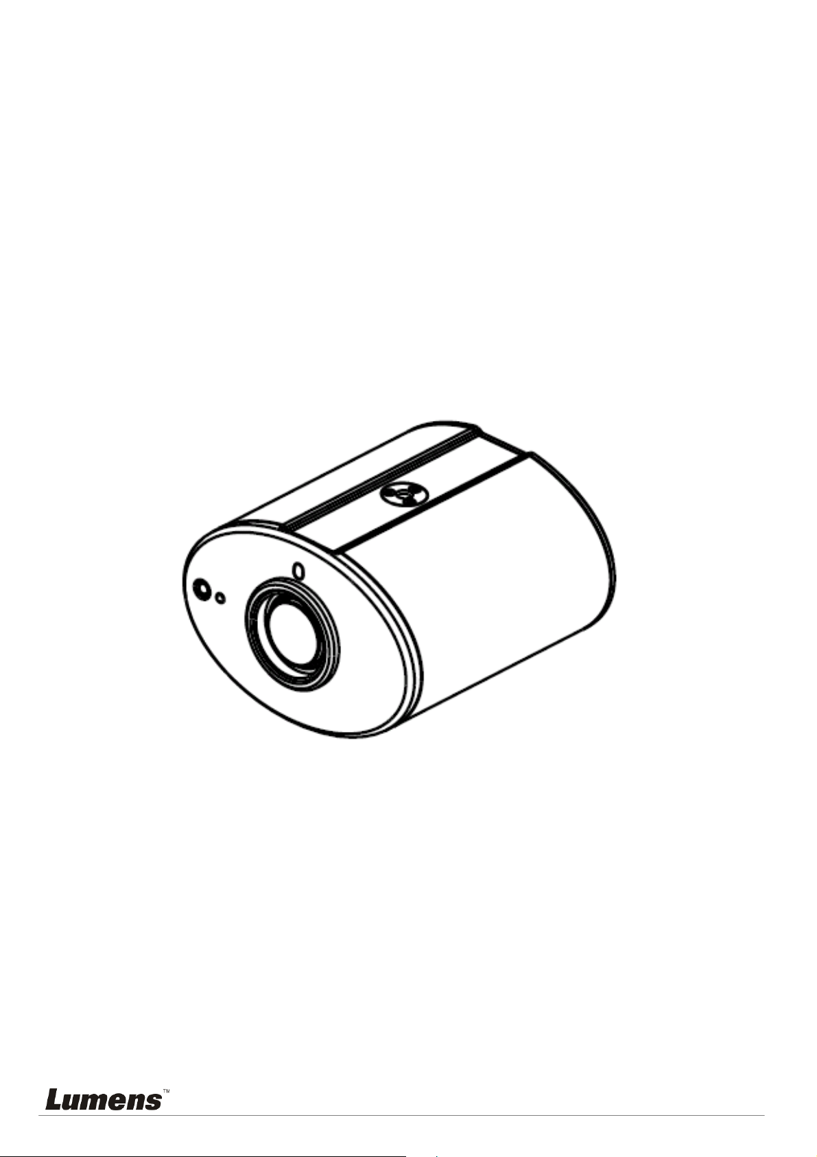
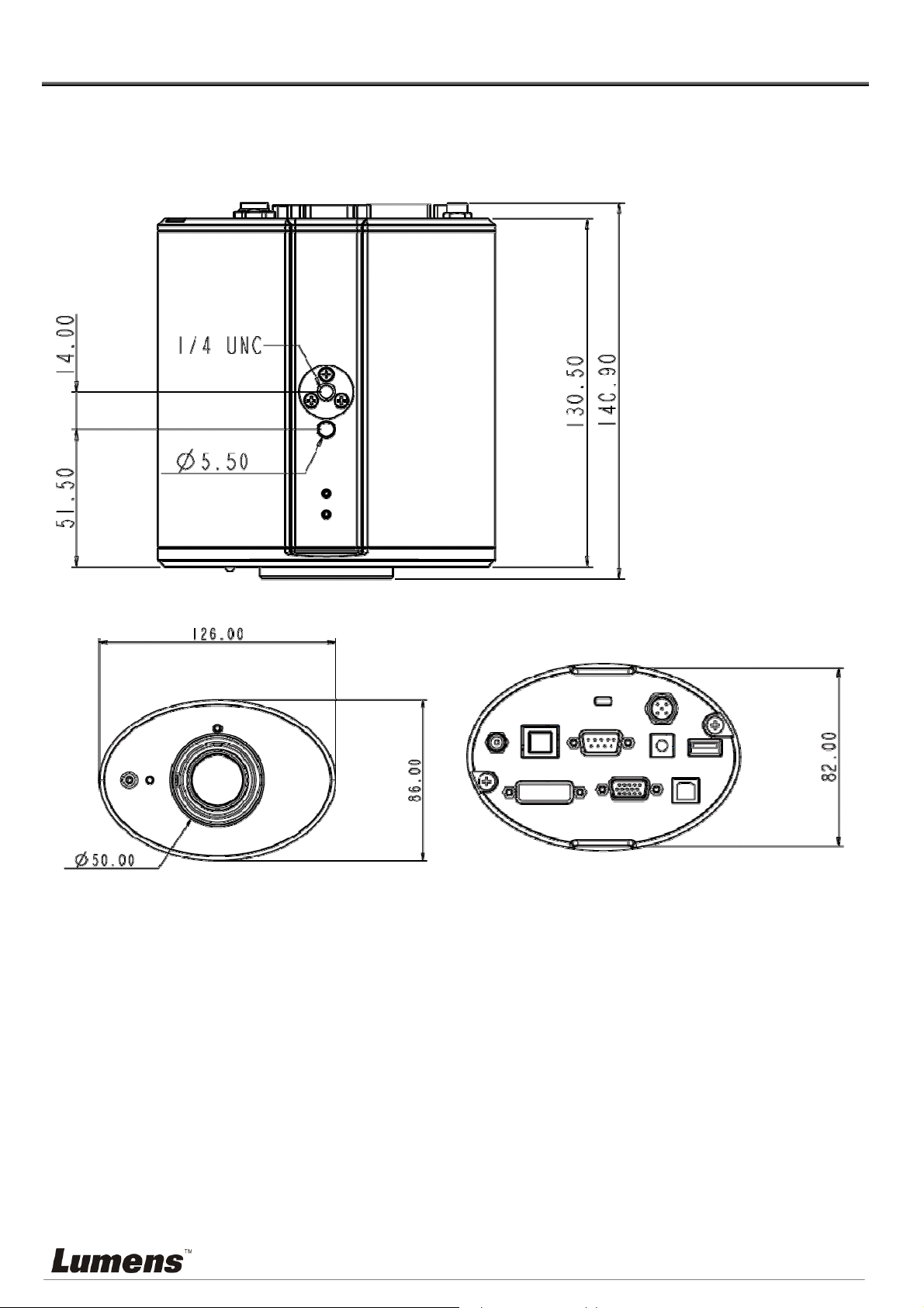
3.1.1 The size of CL510 is as follows:
Length: 126mm
(4.96inch)
Width: 86mm
(3.39inch)
Height: 140.9mm
(5.55inch)
English -
5
Page 7

3.1.2 The size of CL510 together with U-hanger is as follows:
Length: 126mm (4.96inch)
Width: 86mm (3.39inch )
Height: 220mm (8.66inch)
English -
6
Page 8

3.2
IO description
1. DC IN: Power input
2. ETHERNET: RJ-45 Network cable interface
3. DVI OUT: DVI Image out
4. RS232: RS232 Interface
5. VGA OUT: VGA Image out
6. IR: IR Interface
7. DIP SWITCH: DIP Switch setting
8. USB PORT (A-type): USB Port
9. USB PORT (B-type): USB Port
English -
7
Page 9

Chapter 4 Installation and Connections
Installation and connection of CL510 Ceiling Camera requires special skills. To install by yourself,
please follow necessary steps, ensure steady and tight installation of the device, and pay attention to
your safety to avoid any accident.
4.1 Preparation before installation
4.1.1 Ensure the safety of the installation environment. Please do not install the device on
unstable ceiling or in a place where the device is in danger of falling to avoid any
accident.
4.1.2 Please check whether accessories in the box are complete or not. Please contact the
supplier for any shortage, and make sure to keep the accessories in the box intact.
4.1.3 Please choose a proper place for installation of CL510 in advance. Please determine
an installation place according to the following requirements:
4.1.3.1 Confirm the position for the object to be captured.
4.1.3.2 Calculate the height required for hanging the device according to the position of the
object to be captured. If it is not possible to install the device at this height, you need to
change the position of the object to be captured.
4.1.4 Please prepare the following tools for easy installation and shorter installation time:
4.1.4.1 Accessories of CL510 in the box
4.1.4.2 Hanging parts (ceiling mounted hanger, screw for fixing the hanger 1/4-UNC x 4 pcs)
4.1.4.3 Drilling machine, screw driver
4.1.4.4 Ladder
English -
8
Page 10

To achieve the best effect, please ensure that the machine is set at a
distance of not more than 2 meters away from the object to be captured.
2 meters
or less
4.1.5 Schematic diagram for the size of U-hanger and preparation before installation
4.1.5.1 Schematic diagram for the size of U-hanger
The installation personnel should prepare the screw hanger in compliance with the size
of the hole used for securing the U-hanger. (The screw hanger should be used with
UL-Listed approval.)
English -
9
Page 11

4.1.5.2 Installation steps
Adjust the DIP SWITCH to the desired output specifications
Assemble the U-hanger and the device using screws supplied.
Please follow the instruction for the screw hanger to install it on the ceiling.
Screw the device onto the screw hanger and complete the installation.
4.2 Switch setting
<Note> You should unplug and reconnect the power cord, and then restart the CL510 for all
DIP switch settings to take effect.
Output Mode Position of DIP Switch
Default
(XGA)
SXGA
WXGA
UXGA
1080P
0
1
2
3
4
English -
10
Page 12

11
4.3 System diagram
Router or
hub
Computer
(1)
IR extender
Projector or
monitor
Computer
(2)
4.4
Set up the power frequency
Set the applicable power frequency depending on different regions. Please refer to
Appendix 1 for applicable frequency.
4.4.1 After using the remote control to turn on the power, press [MENU] on the remote control to
enter the Service Menu.
4.4.2 Press [] or [] to the [Advanced] menu.
4.4.3 Press [] to the [Power Frequency].
4.4.4 Press [] or [] to adjust the frequency.
4.4.5 Press [MENU] to exit.
4.5 Set the position of the object to be captured (Laser mark)
4.5.1 Prepare a cross point screw driver.
4.5.2 After using the remote control to turn on the power, press [LASER] on the remote control to
enable the laser mark (the red cross round box).
4.5.3 Press [FREEZE] -> [DEL] -> [] on the remote control to enable the center positioning mark
(the blue round box).
4.5.4 Use a cross point screw driver to adjust the laser knob of the machine (the adjustment
should be made at the place marked by the red box in the following figure).
English -
Page 13

Adjust right and left
Adjust up and down
4.5.5 Adjust the cross laser mark (red box) deviated on the screen to the center point of the blue
positioning mark, as shown in the following figure:
4.6 AF Table Set for auto focus setting
4.6.1 Set up AF table
This setting can speed up the AF operation.
1. Press [FREEZE] -> [DEL] -> [ENTER] on the remote control to enter the Service Menu.
2. Press [] or [] to select the [Image] menu.
3. Press [] to <Without Close-up Lens> -> [Focus Table], and press [Enter] to activate the
Focus Table.
<Note> If Close-up Lens (Optional) was installed, select <With Close-up Lens> for
operation.
4. Press [MENU] to select [Adjust], and press [Enter] to adjust.
5. Press [MENU] to select [Save], and press [Enter] to save.
6. Press [] or [] to select [Yes], and press [Enter] to save it.
English -
12
Page 14

4.6.2 Set up the Default Zoom
1. Press [FREEZE] -> [DEL] -> [ENTER] on the remote control to enter the Service
Menu.
2. Press [] or [] to select the [Image] menu.
3. Press [] to <Without Close-up Lens> -> [ Default Zoom Setting].
<Note> If Close-up Lens (Optional) was installed, select <With Close-up Lens>
for operation.
4. Press [] or [] to enter the type required. (The setting is subject to posterior
changes made to AF Table)
5. Press [MENU] to exit the Service Menu.
6. Press [MENU] again to enter the [Advanced], and activate [Factory Reset].
English -
13
Page 15

Chapter 5 Troubleshooting
This chapter describes problems you may encounter while using CL510. If you have questions,
please refer to related chapters and follow all the suggested solutions. If the problem still occurred,
please contact your distributor or the service center.
1. Why cannot I start the device even when I use the PoE?
ANS: Please confirm if your network communication device is supported for Power over Ethernet
(PoE).
2. Does “Please set up the Focus table” appear on the screen when the device is started?
ANS: Please follow the steps of 4.6 AF Table Set for auto focus setting.
3. Why does out of focus still occur when AUTO TUNE is activated?
ANS: Please confirm if there is any fingerprint or stain on the lens. Try to refocus after cleaning the
lens.
English -
14
Page 16

Attachment 1
World voltage & frequency
Frequency
Region/Country
Chinese English Chinese English Chinese English
Region/Country
Frequency
Region/Country
Frequency
阿 富 汗
阿 爾 及 利 亞
安 哥 拉
安 地 瓜
阿 根 廷
澳 洲
澳 地 利
亞 述 爾
巴 哈 馬
巴 林
孟 加 拉
巴 貝 多
比 利 時
Afghanistan 50
Algeria 50
Angola 50
Antiqua 50
Argentina 50
Australia 50
Austria 50
Azores 50
Bahamas 60
Bahrain 60
Bangladesh 50
Babados 50
Belgium 50
大 陸
哥 倫 比 亞
剛 果
哥 斯 大 黎 加
古 巴
塞 普 路 斯
捷 克
達 荷 美
丹 麥
多 明 尼 加
杜 貝
厄 瓜 多 爾
埃 及
China 50
Colombia 60
Congo 50
Costa Rica 60
Cuba 60
Cyprus 50
Czechoslovakia 50
Dahomey 50
Den mark 50
Dominican 60
Dubai 50
Ecuador 60
Egypt 50
關 島
石 榴 島
瓜 地 馬 拉
幾 內 亞
蓋 亞 納
海 地
夏 威 夷
宏 都 拉 斯
香 港
匈 牙 利
冰 島
印 度
印 尼
Guam 60
Grenada 50
Guatemala 60
Guinea 50
Gayana 50
Haiti 60
Hawaii 60
Honduras 60
Hong Kong 50
Hungary 50
Ice land 50
India 50
Indonesin 50
百 慕 達
玻 利 維 亞
波 札 那
巴 西
保 加 利 亞
緬 甸
蒲 隆 地
高 棉
喀 麥 隆
加 拿 大
康 那 利 群 島
中 非 共 和 國
Bermuda 60
Bolivia 50
Botswana 50
Brazil
Bulgaria 50
Burma 50
Burundi 50
Cambodia 50
Cameroon 50
Canada 60
CanaryIsland 50
Central Africa
Rep.
50
60
50
薩 爾 瓦 多
赤 道 幾 內 亞
衣 索 匹 亞
法 羅 群 島
裴 濟
芬 蘭
法 國
蓋 亞 那
加 彭
甘 比 亞
德 國
迦 納
El Salvador 60
Equatorial
Guinea
Ethiopia 50
Faeroe Island 50
Fiji 50
Finland 50
France 50
French
Guiana
Gabon 50
Gambia 50
Germany 50
Ghana 50
50
50
伊 朗
伊 拉 克
愛 爾 蘭
曼 島
以 色 列
義 大 利
象 牙 海 岸
牙 買 加
日 本
約 旦
肯 亞
韓 國
Iran 50
Iraq 50
Ireland 50
Isle of Man 50
Israel 50
Italy 50
Ivory Coast 50
Jamaica 50
Japan
Jordan 50
Kenya 50
Korea 60
50
60
錫 蘭
查 德
海 峽 群 島
Ceylon 50
Chad 50
Channel
Island
English -
直 布 羅 陀
大 不 列 顛
希 臘
50
Gibraltar 50
Great Britain 50
Greece 50
科 威 特
黎 巴 嫩
賴 索 托
Kuwait 50
Lebanon 50
Lesotho 50
15
Page 17

Region/Country
Frequency
Region/Country
Frequency
Region/Country
Chinese English Chinese English Chinese English
Frequency
智 利
利 比 亞
盧 森 堡
澳 門
馬 得 拉 群 島
馬 約 卡 島
馬 拉 加 西
馬 拉 威
馬 來 西 亞
馬 利
馬 爾 他
馬 丁 尼 克 島
茅 里 塔 尼 亞
Chile 50
Libya 50
Luxembourg 50
Macao 50
Madeiral 50
Majokca
Island
50
Malagasy 50
Malawi 50
Malaysia 50
Mali Rep. 50
Malta 50
Martinique 50
Mauritania 50
格 陸 蘭
阿 曼
巴 基 斯 坦
巴 拿 馬
巴 拉 奎
秘 魯
菲 律 賓
波 蘭
葡 蔔 牙
波 多 黎 各
科 托
羅 德 西 亞
羅 馬 尼 亞
Greenland 50
Oman 50
Pakistan 50
Panama 60
Paraguay 50
Peru 60
Philippines 60
Poland 50
Portugal
〞 千 里 達
Puerto Rico 60
Qatar 50
Rhodesia 50
Romania 50
賴 比 瑞 亞
敘 利 亞
大 溪 地
中 華 民 國
坦 尚 尼 亞
泰 國
多 哥 共 和 國
東 加
他 巴 哥
突 尼 西 亞
土 耳 其
烏 干 達
Liberia 60
Syria 50
Tahiti 60
R.O.C.
Taiwan
60
Tanzania 50
Thailand 50
Togo Rep.of 50
Tonga 50
Trinidad 60
Tobago 60
Tunisia 50
Turkey 50
Uganda 50
模 里 西 斯
墨 西 哥
摩 那 哥
蒙 特 色 納 島
摩 洛 哥
莫 桑 鼻 克
尼 泊 爾
荷 爾
新 蘇 格 蘭
紐 西 蘭
尼 加 拉 瓜
尼 日
Mauritius 50
Mexico 60
Monaco 50
Montserrat 60
Morocco 50
Mozambique 50
Nepal 50
Netherlands 50
New
Caledonia
50
New Zealand 50
Nicaragua 60
Niger 50
盧 安 達
沙 烏 地
阿 拉 伯
蘇 格 蘭
塞 內 加 爾
獅 子 山
新 加 坡
索 馬 利 亞
南 非 共 和 國
西 班 牙
斯 里 蘭 卡
蘇 丹
蘇 利 南
Rwanda 50
Saudi Arabia
50
60
Scotland 50
Senegal 50
Sierra Leone 50
Singapore 50
Somalia 50
South Africa
Rep.
50
Spain 50
Sri Lanka 50
Sudan 50
Surinam 60
美 國
蘇 聯
英 國
上 伏 塔
烏 拉 奎
委 內 瑞 拉
越 南
維 爾 京 群 島
西 薩 摩 亞
葉 門 亞 丁
葉 門 阿 拉 伯
南 斯 拉 夫
USA. 60
USSR 50
United
Kingdom
50
Upper Volta 50
Uruguay 50
Venezuela 60
Viet-Nam 50
Virgin Island 60
Western
Samoa
50
Yeman (Aden) 50
Yemen (Arab) 50
Yugoslavia 50
奈 及 利 亞
挪 威
琉 球
Nigeria 50
Norway 50
Okinawa 60
English -
史 瓦 濟 蘭
瑞 典
瑞 士
Swaziland 50
Sweden 50
Switzerland 50
薩 伊 共 和 國
尚 比 亞
Zaire Rep. of 50
Zambia 50
16
 Loading...