

LUMENE ShowPlace HD, ShowPlace HD 210C, ShowPlace HD 240C, ShowPlace HD 270C, ShowPlace HD 300C User Manual

Mode d’emploi
User manual
www.lumene-screens.comUpdate : 12/09/2018


Mode d’emploi
User manual
Français.................................................................4
English ................................................................14

FR
Félicitations et merci d’avoir choisi cet écran de projection LUMENE. Cet écran a été créé pour vous offrir une image
claire, lumineuse et contrastée. Il est également d’une grande fiabilité et très simple d’emploi.
Cet écran a été conçu pour être installé dans tous types de faux-plafonds. Il doit être installé à l’endroit le plus
approprié pour fonctionner avec le projecteur. Une installation correcte garantit un bon fonctionnement et une
sécurité d’utilisation de l’écran.
Lors du déballage, vérifiez la présence des pièces ci-dessous dans le colis. Nous vous recommandons vivement de
conserver l’emballage et ce mode d’emploi pour d’éventuels usages ultérieurs.
Veuillez lire attentivement ce mode d’emploi avant l’installation de votre écran.
SOMMAIRE
Contenu.........................................................................................................................................................4
Schémas et dimensions..................................................................................................................................5
Installation ....................................................................................................................................................6
Méthodes de commande................................................................................................................................9
Réglage des butées (Extra-drop)..................................................................................................................11
Précautions d’utilisation................................................................................................................................13
Garantie.......................................................................................................................................................13
CONTENU
x1
Cache plafond gauche avec
panneau de contrôle IR
x1
Cache plafond droit
x2 x1
4
x1
Clé de réglageTige filetée 500 mm
Télécommande IR

SCHÉMAS ET DIMENSIONS
Support de fixation
FR
Support de fixation
L
B3
B1
Cache plafond
Dimensions de découpe
Longueur de découpe : L - 25 mm
Largeur de découpe : 115 mm
Hauteur du plafond : >122 mm
W
Ld2
Lz
distance entre les trous de montage
119 mm
H
104 mm
Cache plafond
B1
B2
200C 240C 270C 300C
92” 106” 120” 138”
W 2032 2346 2656 3050
H 1146 1320 1494 1716
B1 50 50 50 51
B2 30 30 30 30
B3 800 630 450 300
Ld2 2185 2499 2809 3205
L 2297 2611 2921 3317
Lz 2221 2535 2845 3241
Côté gauche
Côté droit
5

INSTALLATION
FR
1
2
Découper le faux-plafond en fonction de la taille de l’écran (voir le tableau page précédente).
Repérer l’emplacement des vis de montage sur le carter, puis marquer l’emplacement sur le plafond.
Trou de fixation
3
Percer le plafond aux emplacements marqués, puis placer des chevilles de fixation (non fournies).
Couper les tiges filetées à la hauteur désirée, puis les fixer dans le plafond.
Les tiges filetées doivent être
perpendiculaires au plafond
Plafond
16mm
mini
Les tiges filetées ne doivent
pas être à moins de 16mm
du cache plafond
• Choisissez des chevilles adaptées au matériau du plafond (bois, béton...), et pouvant supporter
le poids de l’écran.
• L’utilisation d’un niveau est recommandée afin de vérifier la verticalité des tiges filetées.
• Si le plafond est trop haut, il est possible d’ajouter des extensions pour tiges filetées.
6

4
FR
Présenter l’écran sous l’ouverture du faux-plafond, brancher l’alimentation, puis insérer les tiges filetées
dans les emplacements prévus sur les côtés du carter.
5
Tout en maintenant l’écran horizontal, serrer les écrous anti-chute. Vérifier à l’aide d’un niveau que l’écran
est bien droit et aligné au faux-plafond, puis serrer les écrous de blocage.
Écrou anti-chute
Écrou de blocage
• L’utilisation d’un niveau est recommandée afin de vérifier la bonne horizontalité de l’écran.
7

FR
6
7
Connecter le cache de plafond gauche à l’interface IR.
Positionner les 2 caches de part et d’autre de
l’écran, vérifier que l’espace disponible est
identique de chaque côté. Faire des ajustements
si besoin.
8
Interface IR
Vérifier que les 2 caches sont alignés avec le
carter et le plafond, puis pousser fermement
pour les clipser sur le carter.
espace pour
le cache
Perforation pour
désassemblage
Remarque : Si les caches ne sont pas bien alignés, il
est possible de les déclipser avec un trombone. Il suffit
d’insérer l’extrémité du trombone dans la perforation
prévue à cet effet pour désassembler les caches.
• Les caches de plafond ne sont pas interchangeables. Veillez à bien les installer.
Pousser
horizontalement
Enclencher
fermement
Trombone
8

MÉTHODES DE COMMANDE
Télécommande IR / Télécommande RF (en option)
1
FR
Interface RS485/RS232
et contact sec
Commande
manuelle
Interface IR
Fonctionnement
• Appuyer sur le bouton « up » pour faire remonter l’écran.
• Appuyer sur le bouton « stop » pour arrêter l’écran.
• Appuyer sur le bouton « down » pour faire descendre l’écran.
Appairage :
• Brancher l’alimentation de l’écran.
• Le mode « appairage » est activé pendant 10 secondes.
• Durant ce laps de temps, appuyer sur les boutons « up » et « stop » simultanément.
• L’appairage est réussi si l’écran descend et remonte de quelques centimètres.
Suppression de l’appairage :
• Débrancher puis rebrancher l’alimentation de l’écran.
• Le mode « appairage » est activé pendant 10 secondes.
• Durant ce laps de temps, appuyer sur les boutons « up » et « stop » simultanément pour effacer la mémoire.
• L’appairage est supprimé.
LED
Capteur IR/RF
Up
Stop
Down
Télécommande IR Télécommande RF
(en option)
Up
Stop
Down
Rayon d’action
jusqu’à 60°
Portée :
Télécommande IR :
jusqu’à 12m, ± 60°
Télécommande RF :
jusqu’à 20m
• Le mode « appairage » ne s’active que lors du branchement de l’écran. Pour activer le mode
« appairage » si votre écran est déjà installé, il faut débrancher puis rebrancher l’écran.
• Si l’appairage n’a pas réussi, ou si vous souhaitez ré-appairer la télécommande, il est nécessaire de
débrancher puis rebrancher l’écran, afin d’activer le mode « appairage ».
• La manipulation doit se faire dans les 10 secondes après le branchement.
9

Commande manuelle
2
Le bouton de contrôle manuel est situé sur la gauche
du carter et fonctionne en cycle.
Contrôle externe
3
UP
FR
STOP
DOWN
STOP
Brancher le connecteur RJ12 6P6C.
De gauche à droite :
- 3-6 : câble de contrôle
- 3 : câble commun
- 4 : Stop
- 5 : Down
- 6 : Up
Contrôle RS232 / RS485
4
De gauche à droite :
- 1-2 : câble de contrôle
RS485 :
- 1 : D-
- 2 : D+
RS232 :
voir schéma ci-contre
6P6C
EXTERNAL
CTRL
Branchements
TXD
GND
RJ12
6P6C
P1
DB-9
UP
DOWN
STOP
COM
Contrôle trigger
Séquences RS232 (en hexadécimal)
Monter : FF EE EE EE DD
Arrêter : FF EE EE EE CC
Descendre : FF EE EE EE EE
Dans certains cas, une commande
hexadécimale sera nécessaire pour
autoriser le contrôle RS232 :
FF EE EE EE AA
Réglages
Bits/sec : 2400
Bits de données : 8
Parité : aucune
Bits d’arrêt : 1
Contrôle de flux : aucun
Contrôle avec trigger sans fil 12V (en option)
5
Il est possible de contrôler l’écran via un trigger sans fil 12V (en option) et une télécommande RF (en option).
• Appairer la télécommande RF avec l’écran (voir procédure page précédente).
• Appuyer sur le bouton P2 à l’arrière de la télécommande, puis appuyer sur le bouton d’appairage du
trigger 12V.
10

RÉGLAGE DES BUTÉES BASSES ET HAUTES (EXTRADROP)
FR
EXTRADROP
ZONE DE PROJECTION
ATTENTION :
• Par défaut, les butées de l’écran sont parfaitement réglées. Nous ne recommandons aucun
ajustement afin d’éviter les dégâts potentiels sur le produit. Contactez-notre service après-vente
pour plus d’informations.
• Tout dommage résultant d’un mauvais réglage effectué par l’utilisateur ne sera pas pris en compte
par la garantie de ce produit.
• Si vous avez néanmoins besoin de régler à nouveau les butées de l’écran, référez-vous aux instructions
suivantes. Veillez à effectuer ces réglages avec la plus grande précaution.
POUR TOUT RÉGLAGE DE L’ÉCRAN, NOUS CONSIDÉRONS QUE NOUS REGARDONS LE CARTER PAR LE DESSOUS (IMPORTANT
POUR LES SENS HORAIRES ET ANTI-HORAIRES).
L’extradrop est la zone noire de la toile d’un écran Lumene située au-dessus de
la zone de projection. La hauteur de cette bande noire peut être ajustée afin de
positionner verticalement la zone de projection.
1
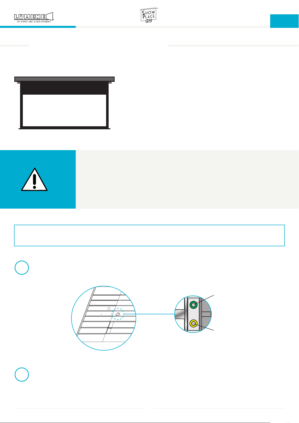
2
Localiser l’emplacement des vis de réglage : sur le côté gauche du carter se trouve une ouverture laissant
apparaître deux vis.
Vis verte
Vis jaune
Déclencher brièvement l’ouverture de l’écran, de façon à faire descendre la toile légèrement. À l’aide de la
clé de réglage fournie, procéder à l’ajustement des butées. (suite page suivante)
11

3
FR
Réglage de la butée de déroulement (butée basse / Extradrop) - Vis JAUNE
4
Sens horaire : butée plus haute
Pour ce réglage, l’action n’est pas
directement visible sur la toile. Il faut
d’abord effectuer le réglage, puis
faire remonter et redescendre la toile
à l’aide de la télécommande.
Sens anti-horaire : butée plus basse
Pour ce réglage, l’action est
directement visible car la toile
redescend par crans successifs.
Réglage de la butée d’enroulement (butée haute) - Vis VERTE
Sens horaire : butée plus basse
Pour ce réglage, l’action n’est pas
directement visible sur la toile. Il faut
d’abord effectuer le réglage, puis
faire remonter et redescendre la toile
à l’aide de la télécommande.
Sens anti-horaire : butée plus haute
Pour ce réglage, l’action est
directement visible car la toile
redescend par crans successifs.
Interrupteur de
sur-rétractation
Barre de lestage
Remarque : L’écran est équipé d’un système de
protection en cas de sur-rétractation de la toile.
Lorsque la toile dépasse le seuil de rétractation,
la barre de lestage actionne un interrupteur qui la
fait redescendre automatiquement afin d’éviter tout
dommage. Quand cela arrive, il est nécessaire de
réajuster la butée haute.
12

FR
Conditions importantes de fonctionnement
La mise en marche de votre écran est très facile mais doit être faite avec
précaution afin d’assurer sa durabilité. Avant la première utilisation, vérifiez
toujours que votre écran soit positionné de manière stable et horizontale.
Précautions :
- Ne rien placer ou accrocher sur l’écran lorsque celui-ci est déployé.
- Ne pas mettre votre doigt à l’intérieur du carter quand vous rétractez la toile
de l’écran.
- Les poussières et éraflures réduisent la qualité de l’image. Aussi, prêtez tout
particulièrement attention aux consignes suivantes :
a. Ne pas toucher la surface de l’écran avec les mains.
b. Ne pas dessiner sur l’écran.
c. Ne pas rayer l’écran avec des objets durs et tranchants
susceptibles de l’endommager.
d. Ne jamais employer de produits chimiques pour laver la surface
de l’écran.
- S’assurer de l’absence d’insectes et de débris divers avant la rétractation de
l’écran.
- Pour enlever la poussière sur la toile, utiliser un chiffon sec, une brosse à poils
doux et frotter délicatement.
- Refermer l’écran afin de protéger la toile.
NETTOYER AVEC PRÉCAUTION
Moteur
Un système de sécurité arrête le moteur après 4 minutes de fonctionnement.
Quand cela se produit, attendez 2 minutes afin que la température du moteur
atteigne son niveau normal.
- Il n’y a pas besoin d’ajouter de lubrifiant au moteur.
- Les réglages du moteur sont déjà réalisés en sortie d’usine.
- N’ajustez pas le moteur vous-même. Veuillez faire appel à un spécialiste
pour vous aider dans cette tâche.
GARANTIE :
Tous les produits LUMENE sont garantis deux ans à partir de la date
d’achat, lorsqu’ils ont été achetés chez LUMENE, chez un distributeur
LUMENE, ou chez un revendeur agréé LUMENE. Cette garantie couvre
tous les défauts matériels ainsi que les défauts de fabrication.
Limitations et exclusions :
Tous les produits LUMENE sont garantis deux ans à partir de la date d’achat,
lorsqu’ils ont été achetés chez LUMENE, chez un distributeur LUMENE, ou
chez un revendeur agréé LUMENE. Seul le premier acheteur peut se prévaloir
de cette garantie. À l’exception des cas notés ci-dessous, la garantie couvre
tout défaut matériel ainsi que les défauts de fabrication de ce produit. Les cas
suivants ne sont pas couverts par la garantie :
- le numéro de série a été enlevé, modifié ou rendu illisible.
- endommagements, détériorations ou défauts de fonctionnement provoqués
(par accident, utilisation incorrecte, abus ou négligence) : une mauvaise
utilisation ou un usage inhabituel du produit ; accidents ou négligences tels
que la projection du produit contre une surface dure ; contact avec de l’eau,
de la pluie ou une humidité extrême ; contact avec du sable, de la poussière
ou autres ; contact avec une source de chaleur extrême, ou contact avec de la
nourriture ou un liquide dessus.
- dommages physiques de la surface du produit telle qu’une éraflure, ou toutes
autres altérations de la surface.
- non-respect des instructions fournies avec le produit.
- dommages subis durant toutes expéditions du produit (les réclamations
doivent être adressées au transporteur).
- une réparation ou une tentative de réparation par une personne non autorisée
à réparer ce produit.
- toute cause autre que les défauts du produit, y compris le manque de
connaissances techniques ou d’expérience de l’utilisateur.
Chacun de ces points annule la validité de la garantie.
Qui peut bénéficier de la garantie ?
Seul le premier acheteur peut se prévaloir de cette garantie. Le service de
garantie ne sera assuré que si la facture originale ou la preuve d’achat (portant
la mention de la date d’achat) accompagne le produit défectueux au cours de
la période de garantie. Cette garantie est valide strictement dans le pays de
la vente originale.
Frais pris en charge
Tous les frais de pièces et main-d’œuvre pour les articles couverts par cette
garantie sont pris en charge par LUMENE. Le paiement des frais d’expédition
et d’assurance est traité ci-après.
Comment obtenir le service au titre de la garantie ?
Si le produit doit être réparé pendant la période de garantie, veuillez contacter :
1) le lieu d’achat du produit,
2) le distributeur local agréé pour ce produit,
3) Si vous ne pouvez pas l’identifier, contactez LUMENE.
Le service sous garantie pour cet appareil est disponible strictement dans le
pays de la vente originale. Le distributeur local identifiera le centre technique
le plus proche. Le produit ou les pièces présumées défectueux doivent êtres
expédiés, port et assurances payés, à ce centre technique, accompagnés de
la copie de la facture d’achat avec indication de la date d’acquisition et dans
son emballage d’origine (ou emballage similaire assurant le même niveau de
protection). Lors de votre envoi vous devez obligatoirement inclure :
a) la copie de votre ticket de caisse ou votre preuve d’achat datée,
b) une description écrite de votre problème,
c) le nom et l’adresse du lieu d’achat,
d) votre adresse et votre numéro de téléphone.
Gardez toujours l’original de la preuve d’achat. Veuillez ne pas renvoyer votre
produit à un centre technique sans un accord préalable. Si les réparations
requises sont couvertes par la garantie et si vous avez adressé le produit ou les
pièces au centre technique agréé le plus proche, les frais de port et d’assurance
pour la réexpédition seront pris en charge. Si vous avez besoin d’informations
supplémentaires, veuillez contacter votre revendeur ou distributeur LUMENE
le plus proche.
Limites de responsabilité et exclusions de garanties explicites :
Excepté le cas où ces dispositions sont inapplicables ou illégales au droit
national et/ou à d’autres juridictions : Pour tout produit défectueux, l’unique
responsabilité de LUMENE est de réparer ou remplacer le produit. En aucun
cas, LUMENE ne peut avoir de responsabilité contractuelle ou délictuelle (y
compris en cas de négligence dans l’utilisation du produit) que ce soit pour
tous les dommages ayant une valeur supérieure au prix d’achat, ou pour tout
autre type de dommage indirect, contingent, entrainant une perte de revenu,
de profits, ou toute autre perte financière en rapport ou pas avec la capacité
ou l’incapacité à utiliser le produit. Tous les dommages sus-cités ne pourront
être réclamés en vertu de la loi française. Tout litige ne pouvant être réglé par
la voie de la conciliation préliminaire et se rapportant à l’interprétation ou à
l’exécution de la garantie et des obligations ici contenues feront l’objet d’une
distinction selon les règles de conciliation et d’arbitrage de la Chambre de
Commerce et d’industrie de Paris par un ou plusieurs arbitres conformément à
ses règles. Les lois applicables sont les lois françaises.
13

UK
Congratulations and thank you for choosing a LUMENE projection screen. This screen has been designed to offer a
clear, bright and contrasted image. It is also of a great reliability and very easy to use.
This screen has been designed to fit all types of suspended ceilings. It should be installed at the most proper place
where it can work with projector. A correct installation ensures proper functioning and safer use of the screen.
When unpacking, please make sure all the below parts are correct in number and types. We highly recommend you
to retain both packaging and user manual for future use.
Please take time to read this manual carefully before installing your screen.
TABLE OF CONTENTS
Content.......................................................................................................................................................14
Diagrams & dimensions.................................................................................................................................15
Installation ..................................................................................................................................................16
Control methods..........................................................................................................................................19
Extradrop settings....................................................................................................................................... 21
Precautions for use.......................................................................................................................................23
Warranty......................................................................................................................................................23
CONTENT
x1
Left end cap
with IR interface
x1
Right end cap
x2 x1
14
x1
Limit adjustment key500 mm threaded rod
IR remote control

DIAGRAMS & DIMENSIONS
Left bracket
UK
Right bracket
L
B3
Left end cap
Ceiling cutout size
Cutout length : L - 25 mm
Cutout width : 115 mm
Ceiling height : > 122 mm
B1
W
Ld2
Lz
installation distance
119 mm
H
104 mm
Right end cap
B1
B2
200C 240C 270C 300C
92” 106” 120” 138”
W 2032 2346 2656 3050
H 1146 1320 1494 1716
B1 50 50 50 51
B2 30 30 30 30
B3 800 630 450 300
Ld2 2185 2499 2809 3205
L 2297 2611 2921 3317
Lz 2221 2535 2845 3241
Left side
Right side
15

INSTALLATION
UK
1
2
Cut the suspended ceiling based on the screen size (see chart on previous page).
Locate the screw holes on the case, then mark the position on the ceiling.
Screw hole
3
Drill holes in the ceiling on the marked positions. Insert dowels in the drilled holes (not provided).
Cut the threaded rod at desired height and screw them in the ceiling.
Threaded rods must be
perpendicular to the ceiling.
Ceiling
16mm
mini
Keep the threaded rods at
16mm from end caps.
• Choose dowels according to your ceiling material (wood, concrete...) that can support the weight
of the screen.
• We highly recommend the use of a spirit level to make sure the threaded rods are vertical.
• If the ceiling is too high, you can add extensions for threaded rods.
16

4
UK
Hold the screen under the suspended ceiling hole, connect the power, and insert the threaded rods in the
dedicated holes on the sides of the case.
5
While holding the screen horizontally, twist the anti-fall nuts. Using a spirit level, check the screen is well
positioned and aligned with the suspended ceiling, then tighten the lock nuts.
Anti-fall nut
Lock nut
• We highly recommend the use of a spirit level to make sure the screen is horizontal.
17

UK
6
7
Connect the left end cap to the IR interface.
Place both end caps on both sides of the screen,
and check the available space is identical on
each side. Adjust if needed.
8
IR interface
Check both end caps are aligned with case and
suspended ceiling, then push firmly to clip them
on the case.
available
space
Disassemble hole
Note : If the end caps are not well aligned, use a clip to
disassemble them. Insert the tip of a clip in the dedicated
hole and disassemble the end cap.
• Ceiling end caps are not interchangeable. Please make sure to install them correctly.
Push
horizontally
Clip firmly
Clip
18

CONTROL METHODS
IR remote control / RF remote control (optional)
1
UK
RS485/RS232 interface
and dry control
Manual control
IR interface
Daily use
• Press « up » to retract the screen
• Press « stop » to stop the screen
• Press « down » to lower the screen
Pairing :
• Connect the screen to power.
• « Pairing » mode is activated for 10 seconds.
• During this time, press « up » and « stop » simultaneously.
• Pairing is successful when the screen goes down and up for a few inches.
Un-pairing :
• Unplug and reconnect the screen to power.
• « Pairing » mode is activated for 10 seconds.
• During this time, press « up » and « stop » simultaneously to clear memory.
• Pairing is removed.
LED
Up
Stop
Down
IR remote control RF remote control
(optional)
Up
Stop
Down
IR/RF sensor
Range :
IR remote control :
up to 12m, ± 60°
RF remote control :
up to 20m
Effective range
up to 60°
• « Pairing » mode will be activated when connecting the screen to power. To activate « pairing » mode
if your screen is already installed, you need to unplug and reconnect the screen.
• If pairing failed, or if you want to pair the remote control again, you need to unplug and reconnect
the screen to activate « pairing » mode.
• Handling must be done within 10 seconds after connecting to power.
19

Manual control
2
Manual control button is a cycle control button
and is located on the left side of the case.
External control
3
UP
UK
STOP
DOWN
STOP
Plug RJ12 6P6C connector.
From left to right :
- 3-6 : control signal cable
- 3 : common cable
- 4 : Stop
- 5 : Down
- 6 : Up
RS232 / RS485 control
4
From left to right :
- 1-2 : control cable
RS485 :
- 1 : D-
- 2 : D+
RS232 :
see opposite diagram
6P6C
EXTERNAL
CTRL
Connections
TXD
GND
RJ12
6P6C
P1
DB-9
UP
DOWN
STOP
COM
Trigger control
RS232 sequences (hexadecimal)
Up : FF EE EE EE DD
Stop : FF EE EE EE CC
Down : FF EE EE EE EE
In some cases, you may need to
enable RS232 control by sending hex
command :
FF EE EE EE AA
Settings
Bits/sec : 2400
Data bits : 8
Parity : none
Stop bit : 1
Flow control : none
Wireless 12V trigger control (optional)
5
You also can control the screen with a wireless 12V trigger (optional) and a RF remote control (optional).
• Pair the RF remote control with the screen (see process on previous page).
• Press P2 button on the back of the RF remote control, then press the learning button on the wireless 12V
trigger.
20
LOWER & UPPER STOPS SETTINGS (EXTRADROP)
UK
EXTRADROP
PROJECTION AREA
ATTENTION :
• By default, the stops of the screen are perfectly adjusted. We do not recommend any adjustment
in order to prevent potential damages on the product. Please contact our customer service for any
further information.
• Any damage resulting from an improper adjustment carried out by the user will be excluded from
the warranty of this product.
• However, if you need to set the upper and lower stops of your screen again, follow the instructions
below. Please be sure to make these adjustments with the utmost care.
FOR SCREEN SETTINGS, WE CONSIDER THAT WE LOOK AT THE CASE FROM BELOW (IMPORTANT FOR CLOCKWISE AND
COUNTER-CLOCKWISE SETTINGS).
The extradrop is the black zone of a Lumene screen located above the projection
area. The height of this black zone can be adjusted so you can position the
projection area vertically.
1
2
Locate the adjusting screws on the screen : on the left side of the case is an opening revealing two screws.
Green screw
Yellow screw
Briefly trigger the opening of the screen, in order to roll down the screen for a few inches. Using the
provided adjustment key, adjust the stops. (continued on next page)
21

3
UK
Adjusting the lowering stop (lower stop / Extradrop) - YELLOW screw
4
Clockwise : upper stop
This adjustment will not be directly
visible on the screen. You will first
need to make the adjustment, and
then raise and re-lower the screen
using the remote control.
Counter-clockwise : lower stop
This adjustment is directly visible
because the screen relows by
successive notches.
Adjusting the raising stop (upper stop) - GREEN screw
Clockwise : lower stop
This adjustment will not be directly
visible on the screen. You will first
need to make the adjustment, and
then raise and re-lower the screen
using the remote control.
Counter-clockwise : upper stop
This adjustment is directly visible
because the screen relows by
successive notches.
Over-limit
protection switch
Bottom bar
Note : The screen is equipped with an over-limit
protection switch. When the canvas exceeds the
retractation threshold, the bottom bar activates
a switch making it go down to avoid any damage.
When this happens, you need to readjust the upper
stop (green screw).
22

UK
Important operating considerations
Setting up is very easy but has to be done carefully to ensure its durability.
Before first use, always position your screen horizontally on a stable and flat
surface.
Warning:
- Don’t hang or put anything on the top of the screen case when your screen
when your screen is unrolled.
- Don’t put your finger inside the case when you retract the screen fabric back
to the case.
- Dust and scratches will lower the image of projection quality. Please pay
particular attention to the following points:
a. Do not touch the screen surface with your hand.
b. Do not draw on the screen surface.
c. Do not cruff or scratch the screen with hard sharp items subject to
cause damage.
d. Never use chemicals to clean the screen surface.
- Make sure there is nothing on the screen before you retract it into the case.
- To remove dust on the cloth, use a dry and soft-haired brush and rub it
delicately.
- Close the screen to protect the cloth.
CLEAN SOFTLY
Motor
The motor will shut down after 4 minutes of use according to the self-protect
purpose. When it occurs, you have to wait for 2 minutes to let the temperature
of the motor come down.
- There is no need to add lubricant to the motor.
- The motor is already in the right position in as it leaves the factory.
- Do not regulate the motor by yourself. Please call a specialist to help you on
this.
LIMITED WARRANTY :
All LUMENE produds carry a two-year limited warranty period when
purchased from LUMENE, a LUMENE distributor or a LUMENE authorized
retailer. This warranty covers all defects in materials and workmanship in
the product manufactured by LUMENE.
Warranty limitation and exclusions:
This warranty covers only the products purchased from LUMENE or a LUMENE
authorized retailer or distributor and runs for a two-year period from the date of
the purchase by the first end-user. Except in the following cases, this warranty
covers ony material or manufacturing deffect. This limited warranty is subject
to the following exceptions:
- the serial number has been removed, modified or made illegible.
- the defects or damage result from use of the products in a manner that is not
normal or customary; improper operation or misuse; accident or neglect such
as dropping the products onto hard surfaces; contact with water, rain, extreme
humidity; contact with sand, dirt or the like; or contact with extreme heat, or
spills of food or liquid.
- physical damage to the surface of the product, induding scratches, cracks or
other damage.
- non respect of the instructions supplied with the product.
- damage due to the shipment of the product (claims have to be addressed to
the carrier).
- someone other than LUMENE or its authorized service centers attempts to
maintain, alter, modify or service the product in any way.
- any other damage due to the Iack of technical knowledge or experience of
the user without any link with deffects of the product.
Any of these voids the warranty.
To be eligible for limited warranty coverage:
The limited warranty applies only to the first end-user. Any person exercising a
claim under this limited warranty must show the proof of the date of purchase,
such as the sales receipt or invoice, and that the product was purchased new.
The warranty is strictly limited to the country of the original purchase.
Warranty related expenses:
LUMENE will take charge of all the expenses on parts and labor related to
the repair or the replacement of the products. The expenses related to the
shipping and insurance fees will be shared as described below.
To obtain warranty service:
During the warranty period, to exercise the limited warranty, the purchaser
must first contact:
1) the original place of purchase,
2) the LUMENE local distributor,
3) LUMENE.
The warranty service for this device is limited to the country of original purchase.
You will receive instructions on how to ship the product to the nearest
designated LUMENE authorized Service Center. The product must also be
packed in its original packaging or a similar package insuring an equal degree
of protection. You must ship it with freight, duties and insurance prepaid.
Regardless of where you are instructed to return the product, you must always
include:
a) a copy of your invoice, bill of sale or other comparable proof of purchase.
b) a written description of the problem.
c) the name and location of the place of purchase and, most importantly.
d) your address and telephone number.
Always retain your original proof of purchase. Do not send any product back to
a service center before prior agreement. Upon receipt of the product, LUMENE
or its authorized service center will check the product and will ship you a
repaired or replacement product, freight and insurance expenses prepaid. If
additional information is required, please contact your retailer or the LUMENE
local distributor.
Limitation of liability:
Except where these dispositions are inapplicable or unlawed to state laws or
other jurisdiction rights: For any defective product, LUMENE sole liability is to
repair or replace the product. By no means no event shall LUMENE be liable,
whether in contract or tort (including negligence) for damages in excess of
the purchase price of the product, or for any indirect, incidental, special or
consequential damage of any kind or to any other products, or loss of revenue
or profits, loss of business, or other financial loss arising out of or in connection
with the ability or inability to use the product, to the full extent these damages
may be disclaimed by law. Any litigation, which cannot be regulated by way of
preliminary conciliation and relating to the interpretation or the execultion of
this Warranty and the obligations herein contained will be distinct definitively,
according to the rules of conciliation and arbitration of the International
Chamber of Commerce of Paris, France, by one or more referees named in
accordance with its rules. The applicable law will be the French one.
23

www.lumene-screens.com
Mise à jour : 12/09/2018
 Loading...